Embed Size (px)
Citation preview

016-0171-698 Rev. A 09/20 E35683
Copyright 2020
Slingshot® Field Hub 2.1 Installation
Manual
016-0171-686 Rev. A, E31924
We
Solv
e Gr
eat C
halle
nges
.
DISCLAIMER While every effort has been made to ensure the accuracy of this document, Raven Industries assumes no responsibility for omissions and errors. Nor is any liability assumed for damages resulting from the use of information contained herein.
Raven Industries shall not be responsible or liable for incidental or consequential damages or a loss of anticipated benefits or profits, work stoppage or loss, or impairment of data arising out of the use, or inability to use, this system or any of its components. Raven Industries shall not be held responsible for any modifications or repairs made outside our facilities, nor damages resulting from inadequate maintenance of this system.
As with all wireless and satellite signals, several factors may affect the availability and accuracy of wireless and satellite navigation and correction services (e.g. GPS, GNSS, SBAS, etc.). Therefore, Raven Industries cannot guarantee the accuracy, integrity, continuity, or availability of these services and cannot guarantee the ability to use Raven systems, or products used as components of systems, which rely upon the reception of these signals or availability of these services. Raven Industries accepts no responsibility for the use of any of these signals or services for other than the stated purpose.
1
TABLE OF CONTENTSTable of Contents ................ 1
Field Hub 2.1 Kit Contents: ...1Recommended: .......................1
Overview ............................... 2Updates ...................................2
Installation ............................ 2Best Installation Practices .......2Installation Checklist ...............4
Operation .............................. 5LED Status Indicators .............5Slingshot RTK .........................6Wi-Fi ........................................6Operating Conditions ..............6Installing the SIM Card ............7
Troubleshooting .................. 8
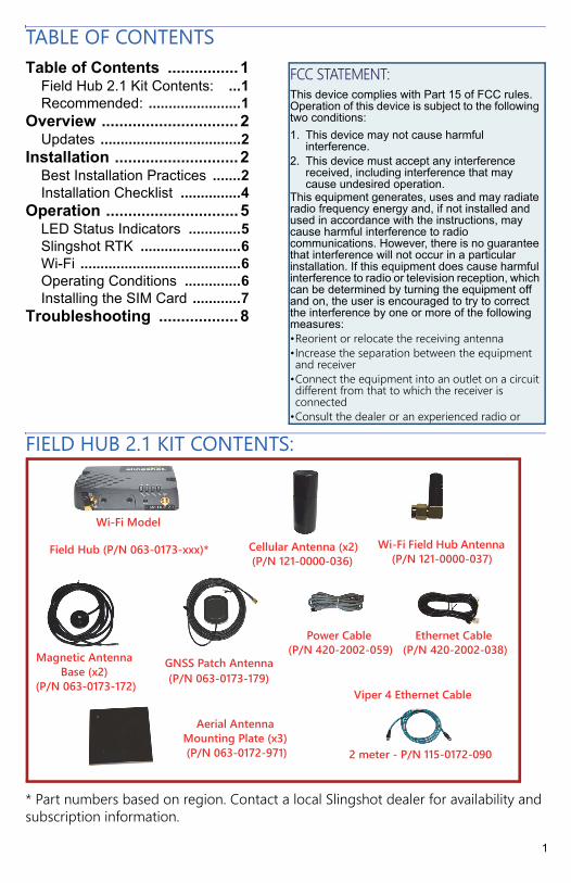
FIELD HUB 2.1 KIT CONTENTS:
* Part numbers based on region. Contact a local Slingshot dealer for availability and subscription information.
FCC STATEMENT:This device complies with Part 15 of FCC rules. Operation of this device is subject to the following two conditions:1. This device may not cause harmful
interference.2. This device must accept any interference
received, including interference that may cause undesired operation.
This equipment generates, uses and may radiate radio frequency energy and, if not installed and used in accordance with the instructions, may cause harmful interference to radio communications. However, there is no guarantee that interference will not occur in a particular installation. If this equipment does cause harmful interference to radio or television reception, which can be determined by turning the equipment off and on, the user is encouraged to try to correct the interference by one or more of the following measures:•Reorient or relocate the receiving antenna•Increase the separation between the equipment and receiver
•Connect the equipment into an outlet on a circuit different from that to which the receiver is connected
•Consult the dealer or an experienced radio or
Magnetic Antenna Base (x2)
(P/N 063-0173-172)
Ethernet Cable (P/N 420-2002-038)
Aerial Antenna Mounting Plate (x3) (P/N 063-0172-971)
GNSS Patch Antenna (P/N 063-0173-179)
Field Hub (P/N 063-0173-xxx)* Wi-Fi Field Hub Antenna (P/N 121-0000-037)
Cellular Antenna (x2) (P/N 121-0000-036)
Wi-Fi Model
Viper 4 Ethernet Cable
2 meter - P/N 115-0172-090
Power Cable (P/N 420-2002-059)
2
OVERVIEWThis document contains recommended installation practices and connection information for the Field Hub 2.1.
The Field Hub provides Internet connectivity and access to service provided by the Slingshot system such as Slingshot Link, Slingshot RTK, Remote Support, and File Transfer. Devices such as the Raven line of field computers may connect to the Internet via the Field Hub. These services are provided via the Slingshot website:
www.ravenslingshot.com
NOTE: A cellular or wireless service provider and a Slingshot subscription are required to access many of the Slingshot services.
UPDATESProduct software and documentation updates may be made available periodically on the Raven Applied Technology web site:
http://portal.ravenprecision.com/
Sign up for e-mail alerts to receive notifications when Raven products updates are available on the Raven website.
At Raven Industries, we strive to make your experience with our products as rewarding as possible. One way to improve this experience is to provide us with feedback on this manual. Your feedback will help shape the future of our product documentation and the overall service we provide. We appreciate the opportunity to see ourselves as our customers see us and are eager to gather ideas on how we have been helping or how we can do better. To serve you best, please send an email with the following information to
-Slingshot® Field Hub 2.1 Installation Manual-016-0171-698 Rev. A-Any comments or feedback (include chapter or page numbers ifapplicable).-Let us know how long have you been using this or other Raven products.
We will not share your email or any information you provide with anyone else. Your feedback is valued and extremely important to us.
3
INSTALLATION
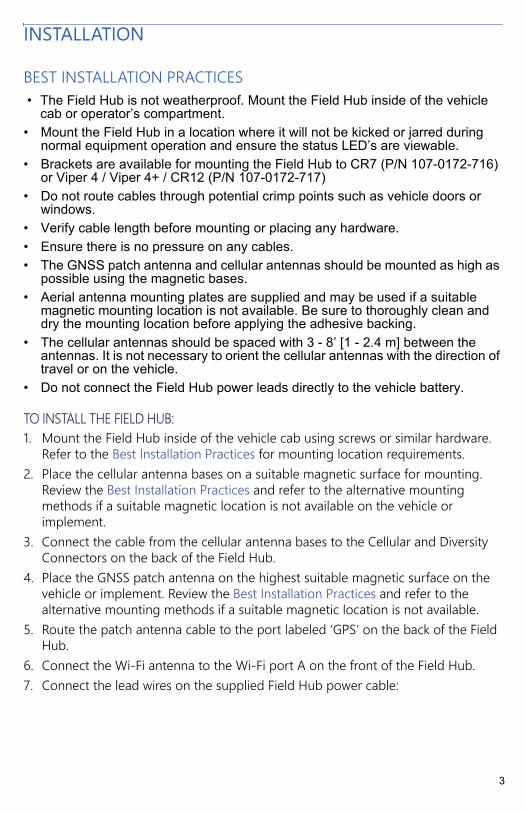
BEST INSTALLATION PRACTICES• The Field Hub is not weatherproof. Mount the Field Hub inside of the vehicle
cab or operator’s compartment.• Mount the Field Hub in a location where it will not be kicked or jarred during
normal equipment operation and ensure the status LED’s are viewable.• Brackets are available for mounting the Field Hub to CR7 (P/N 107-0172-716)
or Viper 4 / Viper 4+ / CR12 (P/N 107-0172-717)• Do not route cables through potential crimp points such as vehicle doors or
windows.• Verify cable length before mounting or placing any hardware.• Ensure there is no pressure on any cables.• The GNSS patch antenna and cellular antennas should be mounted as high as
possible using the magnetic bases.• Aerial antenna mounting plates are supplied and may be used if a suitable
magnetic mounting location is not available. Be sure to thoroughly clean and dry the mounting location before applying the adhesive backing.
• The cellular antennas should be spaced with 3 - 8’ [1 - 2.4 m] between the antennas. It is not necessary to orient the cellular antennas with the direction of travel or on the vehicle.
• Do not connect the Field Hub power leads directly to the vehicle battery.
TO INSTALL THE FIELD HUB:1. Mount the Field Hub inside of the vehicle cab using screws or similar hardware.
Refer to the Best Installation Practices for mounting location requirements.2. Place the cellular antenna bases on a suitable magnetic surface for mounting.
Review the Best Installation Practices and refer to the alternative mounting methods if a suitable magnetic location is not available on the vehicle or implement.
3. Connect the cable from the cellular antenna bases to the Cellular and Diversity Connectors on the back of the Field Hub.
4. Place the GNSS patch antenna on the highest suitable magnetic surface on the vehicle or implement. Review the Best Installation Practices and refer to the alternative mounting methods if a suitable magnetic location is not available.
5. Route the patch antenna cable to the port labeled ‘GPS’ on the back of the Field Hub.
6. Connect the Wi-Fi antenna to the Wi-Fi port A on the front of the Field Hub.7. Connect the lead wires on the supplied Field Hub power cable:
4
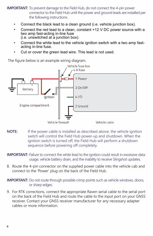
IMPORTANT: To prevent damage to the Field Hub, do not connect the 4-pin power connector to the Field Hub until the power and ground leads are installed per the following instructions.
• Connect the black lead to a clean ground (i.e. vehicle junction box).• Connect the red lead to a clean, constant +12 V DC power source with a
two amp fast-acting in-line fuse(i.e. unswitched at a junction box).
• Connect the white lead to the vehicle ignition switch with a two amp fast-acting in-line fuse.
• Cut or cover the green lead wire. This lead is not used.
The figure below is an example wiring diagram.
NOTE: If the power cable is installed as described above, the vehicle ignition switch will control the Field Hub power-up and shutdown. When the ignition switch is turned off, the Field Hub will perform a shutdown sequence before powering off completely.
IMPORTANT: Failure to connect the white lead to the ignition could result in excessive data usage, vehicle battery drain, and the inability to receive Slingshot updates.
8. Route the 4-pin connector on the supplied power cable into the vehicle cab and connect to the ‘Power’ plug on the back of the Field Hub.
IMPORTANT: Do not route through possible crimp points such as vehicle windows, doors, or sharp edges.
9. For RTK corrections, connect the appropriate Raven serial cable to the serial port on the back of the Field Hub and route the cable to the input port on your GNSS receiver. Contact your GNSS receiver manufacturer for any necessary adapter cables or more information.
5
IMPORTANT: Use only Raven approved serial cables designed specifically for your GNSS receiver, or excess data usage may occur. Contact your local Slingshot dealer for appropriate cable part number and ordering information.
10. Connect the supplied Ethernet cable to the ‘Ethernet’ port on the back of the Field Hub and route to a web compatible device such as a Raven field computer.
11. Place the Field Hub information in a location that is easily visible as it contains information that may be needed in the future.
INSTALLATION CHECKLISTOnce the installation of the Field Hub is complete, verify that the Field Hub is working properly by checking the items in the list below.
NOTE: The Field Hub may take up to 3 minutes to start up. Allow the Field Hub sufficient time to power up.
• Signal LED is solid green or solid yellow.• Network LED is solid green or flashing green/yellow.• Activity LED should be flashing yellow or red (approximately once per
second), with intermittent green flashing if a valid Slingshot RTK subscription has been activated.
• Power LED is green with yellow flashing every four seconds if GPS is acquired.
• Field Hub powers on/off with the ignition.
NOTE: The Field Hub goes through a power down sequence when the ignition key is switched off. It is normal for the Power LED to remain on for approximately 60 seconds after the ignition switch is turned off.
6
OPERATION
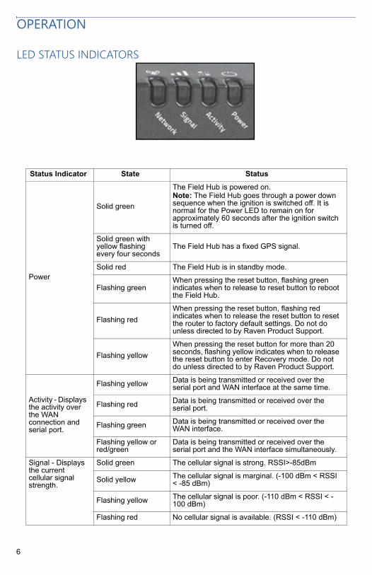
LED STATUS INDICATORS
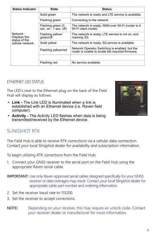
Status Indicator State Status
Power
Solid green
The Field Hub is powered on. Note: The Field Hub goes through a power down sequence when the ignition is switched off. It is normal for the Power LED to remain on for approximately 60 seconds after the ignition switch is turned off.
Solid green with yellow flashing every four seconds
The Field Hub has a fixed GPS signal.
Solid red The Field Hub is in standby mode.
Flashing greenWhen pressing the reset button, flashing green indicates when to release to reset button to reboot the Field Hub.
Flashing redWhen pressing the reset button, flashing red indicates when to release the reset button to reset the router to factory default settings. Do not do unless directed to by Raven Product Support.
Flashing yellowWhen pressing the reset button for more than 20 seconds, flashing yellow indicates when to release the reset button to enter Recovery mode. Do not do unless directed to by Raven Product Support.
Activity - Displays the activity over the WAN connection and serial port.
Flashing yellow Data is being transmitted or received over the serial port and WAN interface at the same time.
Flashing red Data is being transmitted or received over the serial port.
Flashing green Data is being transmitted or received over the WAN interface.
Flashing yellow or red/green
Data is being transmitted or received over the serial port and the WAN interface simultaneously.
Signal - Displays the current cellular signal strength.
Solid green The cellular signal is strong. RSSI>-85dBm
Solid yellow The cellular signal is marginal. (-100 dBm < RSSI < -85 dBm)
Flashing yellow The cellular signal is poor. (-110 dBm < RSSI < -100 dBm)
Flashing red No cellular signal is available. (RSSI < -110 dBm)
7
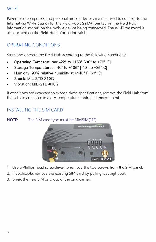
ETHERNET LED STATUSThe LED’s next to the Ethernet plug on the back of the Field Hub will display as follows:• Link - The Link LED is illuminated when a link is
established with an Ethernet device (i.e. Raven field computer).
• Activity - The Activity LED flashes when data is being transmitted/received by the Ethernet device.
SLINGSHOT RTKThe Field Hub is able to receive RTK corrections via a cellular data connection. Contact your local Slingshot dealer for availability and subscription information.
To begin utilizing RTK corrections from the Field Hub:1. Connect your GNSS receiver to the serial port on the Field Hub using the
appropriate Raven serial cable.
IMPORTANT: Use only Raven approved serial cables designed specifically for your GNSS receiver or data overages may result. Contact your local Slingshot dealer for appropriate cable part number and ordering information.
2. Set the receiver baud rate to 115200.3. Set the receiver to accept corrections.
NOTE: Depending on your receiver, this may require an unlock code. Contact your receiver dealer or manufacturer for more information.
Network - Displays the status of the cellular network.
Solid green The network is ready and LTE service is available.
Flashing green Connecting to the network.
Flashing green (3 sec. on - 1 sec. off)
The network is ready, WAN over Wi-Fi (router is in Wi-Fi client mode).
Flashing yellow/green/off
The network is ready, LTE service is not on, and roaming 3G.
Solid yellow The network is ready, 3G service is available.
Flashing yellow/red Network Operator Switching is enabled, but the router is unable to locate the required firmware.
Flashing red No service available.
Status Indicator State Status
Link Activity
8
WI-FIRaven field computers and personal mobile devices may be used to connect to the Internet via Wi-Fi. Search for the Field Hub’s SSID# (printed on the Field Hub information sticker) on the mobile device being connected. The Wi-Fi password is also located on the Field Hub information sticker.
OPERATING CONDITIONSStore and operate the Field Hub according to the following conditions:• Operating Temperatures: -22° to +158° [-30° to +70° C]• Storage Temperatures: -40° to +185° [-40° to +85° C]• Humidity: 90% relative humidity at +140° F [60° C]• Shock: MIL-STD-810G• Vibration: MIL-STD-810G
If conditions are expected to exceed these specifications, remove the Field Hub from the vehicle and store in a dry, temperature controlled environment.
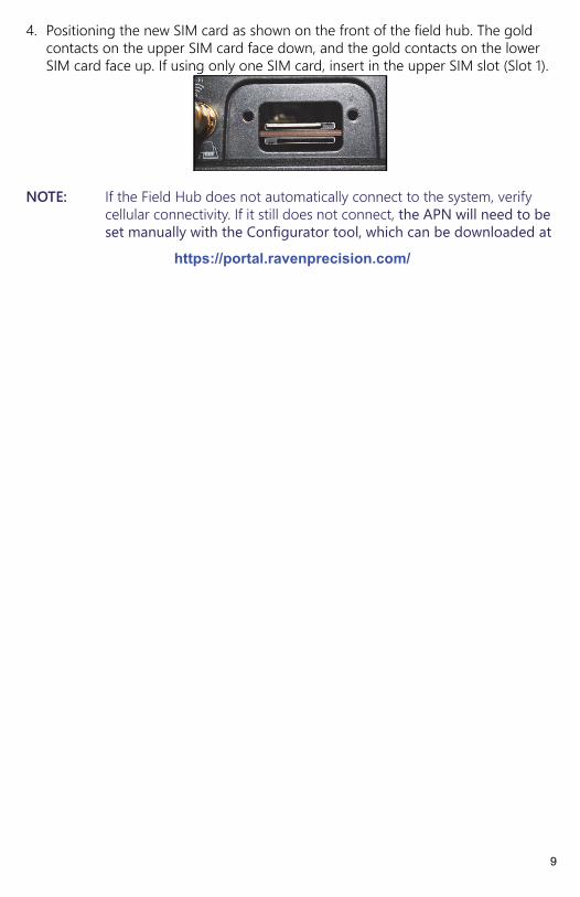
INSTALLING THE SIM CARDNOTE: The SIM card type must be MiniSIM(2FF).
1. Use a Phillips head screwdriver to remove the two screws from the SIM panel.2. If applicable, remove the existing SIM card by pulling it straight out.3. Break the new SIM card out of the card carrier.
9
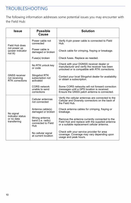
4. Positioning the new SIM card as shown on the front of the field hub. The gold contacts on the upper SIM card face down, and the gold contacts on the lower SIM card face up. If using only one SIM card, insert in the upper SIM slot (Slot 1).
NOTE: If the Field Hub does not automatically connect to the system, verify cellular connectivity. If it still does not connect, the APN will need to be set manually with the Configurator tool, which can be downloaded at
https://portal.ravenprecision.com/
10
TROUBLESHOOTINGThe following information addresses some potential issues you may encounter with the Field Hub:
Issue Possible Cause
Solution
Field Hub does not power up (power indicator not lit)
Power cable not connected
Verify 4-pin power cable is connected to Field Hub.
Power cable is damaged or broken Check cable for crimping, fraying or breakage.
Fuse(s) broken Check fuses. Replace as needed.
GNSS receiver not receiving RTK corrections
No RTK unlock key or code
Check with your DGNSS receiver dealer or manufacturer and verify the receiver has been unlocked or is compatible with RTK corrections.
Slingshot RTK subscription not activated
Contact your local Slingshot dealer for availability or obtain a subscription.
CORS network unable to send corrections
Some CORS networks will not forward correction messages until a GPS location is received. Ensure the GNSS patch antenna is connected.
No signal indicator status or no data transferring
Cellular antennas not connected
Verify the cellular antennas are connected to the Cellular and Diversity connectors on the back of the Field Hub.
Antenna cable(s) damaged or broken
Check antenna cables for crimping, fraying or breakage.
Wrong antenna band (i.e. radio) connected to Field Hub
Remove the antenna currently connected to the Field Hub and replace with the supplied antenna or a suitable replacement cellular antenna.
No cellular signal at current location
Check with your service provider for area coverage. Coverage may vary depending upon usage and peak hours.

016-0171-537 Rev. H, E29761
We
Solv
e Gr
eat C
halle
nges
.
LIMITED WARRANTY WHAT DOES THIS WARRANTY COVER? This warranty covers all defects in workmanship or materials in your Raven Applied Technology Division product under normal use, maintenance, and service when used for intended purpose.
HOW LONG IS THE COVERAGE PERIOD? Raven Applied Technology products are covered by this warranty for 12 months from the date of retail sale. In no case will the Limited Warranty period exceed 24 months from the date the product was issued by Raven Industries Applied Technology Division. This warranty coverage applies only to the original owner and is non-transferable.
HOW CAN I GET SERVICE? Bring the defective part and proof of purchase to your Raven dealer. If the dealer approves the warranty claim, the dealer will process the claim and send it to Raven Industries for final approval. The freight cost to Raven Industries will be the customer’s responsibility. The Return Materials Authorization (RMA) number must appear on the box and all documentation (including proof of purchase) must be included inside the box to be sent to Raven Industries.
WHAT WILL RAVEN INDUSTRIES DO? Upon confirmation of the warranty claim, Raven Industries will (at our discretion) repair or replace the defective product and pay for the standard return freight, regardless of the inbound shipping method. Expedited freight is available at the customer’s expense.

016-0171-537 Rev. H, E29761
We
Solv
e Gr
eat C
halle
nges
.
WHAT IS NOT COVERED BY THIS WARRANTY? Raven Industries will not assume any expense or liability for repairs made outside our facilities without written consent. Raven Industries is not responsible for damage to any associated equipment or products and will not be liable for loss of profit, labor, or other damages. The obligation of this warranty is in lieu of all other warranties, expressed or implied, and no person or organization is authorized to assume any liability for Raven Industries.
Damages caused by normal wear and tear, misuse, abuse, neglect, accident, or improper installation and maintenance are not covered by this warranty.

016-0171-536 Rev. B, E29761
We
Solv
e Gr
eat C
halle
nges
.
EXTENDED WARRANTY WHAT DOES THIS WARRANTY COVER? This warranty covers all defects in workmanship or materials in your Raven Applied Technology Division product under normal use, maintenance, and service when used for intended purpose.
DO I NEED TO REGISTER MY PRODUCT TO QUALIFY FOR THE EXTENDED WARRANTY? Yes. Products/systems must be registered within 30 days of retail sale to receive coverage under the Extended Warranty. If the component does not have a serial tag, the kit it came in must be registered instead.
WHERE CAN I REGISTER MY PRODUCT FOR THE EXTENDED WARRANTY? To register, go online to www.ravenhelp.com and select Product Registration.
HOW LONG IS THE EXTENDED WARRANTY COVERAGE PERIOD? Raven Applied Technology products that have been registered online are covered for an additional 12 months beyond the Limited Warranty for a total coverage period of 24 months from the date of retail sale. In no case will the Extended Warranty period exceed 36 months from the date the product was issued by Raven Industries Applied Technology division. This Extended Warranty coverage applies only to the original owner and is non-transferable.

016-0171-536 Rev. B, E29761
We
Solv
e Gr
eat C
halle
nges
.
HOW CAN I GET SERVICE? Bring the defective part and proof of purchase to your Raven dealer. If the dealer approves the warranty claim, the dealer will process the claim and send it to Raven Industries for final approval. The freight cost to Raven Industries will be the customer’s responsibility. The Return Materials Authorization (RMA) number must appear on the box and all documentation (including proof of purchase) must be included inside the box to be sent to Raven Industries. In addition, the words “Extended Warranty” must appear on the box and all documentation if the failure is between 12 and 24 months from the retail sale.
WHAT WILL RAVEN INDUSTRIES DO? Upon confirmation of the product’s registration for the Extended Warranty and the claim itself, Raven Industries will (at our discretion) repair or replace the defective product and pay for the standard return freight, regardless of the inbound shipping method. Expedited freight is available at the customer’s expense.
WHAT IS NOT COVERED BY THE EXTENDED WARRANTY? Raven Industries will not assume any expense or liability for repairs made outside our facilities without written consent. Raven Industries is not responsible for damage to any associated equipment or products and will not be liable for loss of profit, labor, or other damages. Cables, hoses, software enhancements, and remanufactured items are not covered by this Extended Warranty. The obligation of this warranty is in lieu of all other warranties, expressed or implied, and no person or organization is authorized to assume any liability for Raven Industries.
Damages caused by normal wear and tear, misuse, abuse, neglect, accident, or improper installation and maintenance are not covered by this warranty.