Embed Size (px)
Citation preview
Slim near-eye display using pinhole aperturearraysKAAN AKSIT,* JAN KAUTZ, AND DAVID LUEBKE
NVIDIA Research, 2700 San Tomas Expy, Santa Clara, California 95050, USA*Corresponding author: [email protected]
Received 4 December 2014; revised 12 March 2015; accepted 12 March 2015; posted 13 March 2015 (Doc. ID 228663); published 9 April 2015
We report a new technique for building a wide-angle, lightweight, thin-form-factor, cost-effective, easy-to-manufacture near-eye head-mounted display (HMD) for virtual reality applications. Our approach adoptsan aperture mask containing an array of pinholes and a screen as a source of imagery. We demonstrateproof-of-concept HMD prototypes with a binocular field of view (FOV) of 70° × 45°, or total diagonal FOVof 83°. This FOV should increase with increasing display panel size. The optical angular resolution supportedin our prototype can go down to 1.4–2.1 arcmin by adopting a display with 20–30 μm pixel pitch. ©2015Optical
Society of America
OCIS codes: (110.1220) Apertures; (110.1758) Computational imaging; (330.1400) Vision - binocular and stereopsis.
http://dx.doi.org/10.1364/AO.54.003422
1. INTRODUCTION
Design of a near-eye head-mounted display (HMD) includesmultiple challenges such as achieving a wide field of view(FOV), high optical angular resolution, slim form factor, lightweight, and ease of replication. The use of any reflective, re-fractive, or diffractive components entails a trade-off in oneof these challenges.
Researchers have recently demonstrated various ideas to over-come these challenges. Lanman and Luebke developed an HMD[1] using microlenses in front of a microdisplay for virtual reality(VR) applications, which shares a similar principle with theexisting integral imaging displays/cameras. Their HMD alsoaddressed the problem of the accommodation-vergence conflictthrough a lightfield approach. Maimone and Fuchs demon-strated a unique see-through HMD [2], which uses a stack ofLCD panels. The image in this case is formed computationallythrough modulating each panel with a set of optimized patterns.Most recently, Maimone et al. introduced another see-throughHMD approach [3], which adopts a sparse array of point lightsources with a single spatial light modulator (SLM). This ap-proach achieves a wide binocular FOV of 110° in their prototype.
A recent trend in HMD design is the use of mobile devicedisplays from phones and tablets, which provides very highdensity, typically around ∼300–600 pixels per inch (ppi),and large display dimensions up to around 6 in. diagonal.Some HMD manufacturers take a classical magnifier approachin their design to provide a practical VR experience with mobiledevices, often using the same screen for both eyes. Althoughthis design provides simplicity, it comes with a bulky form fac-tor due to the large focal length of the used lens(es), and it also
introduces optical image distortion problems caused by the re-fractive elements.
In this paper, we propose a novel method to build a light-weight, slim near-eye HMD for VR. Our approach pairs aconventional display with an aperture array, or an array ofpinhole apertures.
Pinholes have been used for various purposes in the displaydomain. Huang et al. demonstrated a visual aberration cor-recting display [4], which works with pinhole parallax barriersand microlenses. Aksit et al. used pinholes with wavelength se-lective filters in front of the eye to address the accommodation-vergence conflict in stereoscopic displays [5]. Both cases have alarge viewing distance. Sprague et al. embed a single pinholeinside a contact lens to avoid bulky imaging optics in HMDdesign [6]. Song et al. propose a lightfield HMD [7] usingfree-form optics combined with a pinhole aperture array.However, to the best of our knowledge, ours is the first systemto use pinhole aperture arrays as a stand-alone image relay layerin an HMD configuration.
We believe our technique is a basis for a framework to buildsimple HMDs with a small number of components. Ourproposal’s main contributions to the domain of HMD researchare itemized as follows:
• We provide a wide FOV, and high optical resolutionHMD design, almost matching the optical capabilities of ahuman eye.
• We provide the simplest optical design to build HMDswith a small number of optical components.
• We provide a thin-form-factor, cost-effective, lightweightsolution, unlike many other designs in industry and research.
3422 Vol. 54, No. 11 / April 10 2015 / Applied Optics Research Article
1559-128X/15/113422-06$15/0$15.00 © 2015 Optical Society of America
• We provide an easily replicable design for researchers in-terested in lightfield and VR research.
2. PROPOSAL
Our proposal is sketched in Fig. 1, in which a pinhole aperturearray is placed at a distance to the cornea of an eye, with adisplay screen at a fixed distance beyond the pinhole aperturearray. When designing such a HMD, we must first choose thedistance of the screen from the eye(s). Given the generallyaccepted 1 arcmin angular visual acuity threshold of a humaneye, we propose to place the screen at the tip of the nose, i.e., at45–50 mm distance from the eye. At this distance, the smallestresolvable feature corresponds to 10–15 μm—a pitch size thedisplay industry should be able to provide in the near future as astandard.
A human eye cannot focus at a distance as small as 45–50 mm. A pinhole can help in this case, as it will boundthe cone of rays that enter the eye’s pupil as shown inFig. 1. In other words, each screen pixel will send an almostangularly bounded beam of light to the eye. The bundle of raysfrom a single pinhole will form an image on the retina, whichare called retinal elemental images. In similar configurations, aFOV of a single pinhole is ∼8°–12°, in which the eye pupildiameter plays a dominant role over the FOV. By increasingthe number of pinholes in our system, the FOV can be wid-ened. We predict a full FOV with a large enough screen andwith enough pinholes.
3. PINHOLE APERTURE ARRAY DESIGN
The mathematical representation of our proposed systemhelped us to find the correct aperture designs for our proto-types. There are two different variables in our system, whichare the cornea to pinhole aperture array distance d ae, andthe pinhole aperture array to screen distance d ai. The rest ofthe variables are either a direct result of the change in thesevariables or constant values.
A constant in our design is the eye pupil size d e , which isequal to the size of the eyebox in our solution. We have chosend e as 8 mm, which varies between 2 and 8 mm in reality [8].Choosing an eyebox bigger than the actual size of an eye pupilwill provide the freedom to compensate for change in gazewithout requiring a pupil tracker. For example, a 4 mm eyepupil size will have enough freedom to gaze at different partsof the screen, when an 8 mm eyebox is designed.
As highlighted earlier, we have chosen d ae � d ai to be45–50 mm. Note that the choice of d ae and d ai directly affectsthe spacing of the pinholes db as shown in Fig. 2(a). UsingFig. 2(a), the spacing of the pinholes can be formalized as
db ≥d ed ai
d ai � d ae
: (1)
The size of a single elemental image d 1 can be calculatedusing Fig. 2(b) as
d 1 �d e�m� d ai�d ae − m
; where m � dad ae
da � d e: (2)
Equation (2) contains the pinhole size da as a variable; da isdirectly correlated with the angular resolution of the system. dahas to be selected in a way that the maximum possible angularresolution is provided. According to Fourier optics, the angular
Fig. 1. 2D sketch showing the image formation on the retina byusing a pinhole aperture array in front of a screen. Each elementalimage consists of N ×N pixels. Depending on the pinhole aperturearray’s distance to the screen (d ai), eye pupil size (d e), cornea to pin-hole aperture array distance (d ae), pinhole diameter (d a), and the spac-ing of the pinholes (db), the retinal elemental images can be made toabut or overlap (as shown here) on the retina.
Fig. 2. 2D sketch showing (a) effect of the changing d ae and d ai
over db and (b) effect of changing da over a single elemental image’ssize (d 1) on screen. Both sketches are valid for a fixed pupil size (d e).
Research Article Vol. 54, No. 11 / April 10 2015 / Applied Optics 3423
resolution of such a system can be calculated using the Rayleighresolution formula (θ ≈ λ∕da); on the other hand, geometricoptics predicts a growing angular spot size on the cornea withincreasing da (θ ≈ da∕�2d ai�). The case in which two estima-tions meet is the optimal pinhole size in terms of angular res-olution, which is given as
da ≈ffiffiffiffiffiffiffiffiffiffi2λd ai
p: (3)
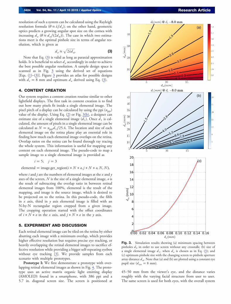
Note that Eq. (3) is valid as long as paraxial approximationholds. It is beneficial to select da accordingly in order to achievethe best possible angular resolution. A sample design space isscanned as in Fig. 3 using the derived set of equations[Eqs. (1)–(3)]. Figure 3 provides an atlas for possible designswith d e � 8 mm and optimum da derived using Eq. (3).
4. CONTENT CREATION
Our system requires a content creation routine similar to otherlightfield displays. The first task in content creation is to findout how many pixels fit inside a single elemental image. Thepixel pitch of a display can be calculated by using the ppi (nppi)value of the display. Using Eq. (2) or Fig. 3(b), a designer canestimate size of a single elemental image (d 1). Once d 1 is cal-culated, the amount of pixels in a single elemental image can becalculated as N � nppid 1∕25.4. The location and size of eachelemental image on the retina plane play an essential role infinding how much each elemental image overlaps on the retina.Overlap ratios on the retina can be found through ray tracingthe whole system. This information is useful for mapping anycontent on each elemental image. The pseudo-code to map asample image to a single elemental image is provided as
i � 5; j � 3
elemental � image:get_region�i � N � o; j � N � o; N ; N �;where i and j are the numbers of elemental images at the x and yaxes of the screen, N is the size of a single elemental image, o isthe result of subtracting the overlap ratio in between retinalelemental images from 100%, elemental is the result of themapping, and image is the source image, which is desired tobe projected on to the retina. In this pseudo-code, the fifthin x axis, third in y axis elemental image is filled with anN-by-N rectangular region cropped from a given image.The cropping operation started with the offset coordinatesof i � N � o in the x axis, and j � N � o in the y axis.
5. EXPERIMENT AND DISCUSSION
Each retinal elemental image can be tiled on the retina by eitherabutting each image with a minimum overlap, which provideshigher effective resolution but requires precise eye tracking, orheavily overlapping the retinal elemental images to sacrifice ef-fective resolution while providing a bigger self-repeating eyeboxwithout eye tracking [3]. We provide samples from eachscenario with multiple prototypes.
Prototype I: We first demonstrate a prototype with over-lapping retinal elemental images as shown in Fig. 4. The proto-type uses an active matrix organic light emitting display(AMOLED) found in a smartphone, with 386 ppi and a5.7 in. diagonal screen size. The screen is positioned at
45–50 mm from the viewer’s eye, and the distance variesroughly with the varying facial structure from user to user.The same screen is used for both eyes, with the overall system
Fig. 3. Simulation results showing (a) minimum spacing betweenpinholes db in order to use screen without any crosstalk; (b) size ofa single elemental image d 1, when da is chosen as in Eq. (3); and(c) optimum pinhole size with the changing screen to pinhole aperturearray distance d ai. Note that (a) and (b) are plotted using a constant eyepupil size (d eye � 8 mm).
3424 Vol. 54, No. 11 / April 10 2015 / Applied Optics Research Article
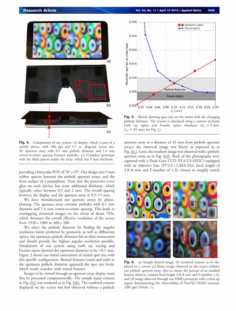
providing a binocular FOV of 70° × 45°. Our design uses 9 mmrubber spacers between the pinhole aperture arrays and thefront surface of a smartphone. Note that the protective coverglass on such devices has some additional thickness, whichtypically varies between 0.5 and 2 mm. The overall spacingbetween the display and the aperture array is 9.5–11 mm.
We have manufactured our aperture arrays by photo-plotting. The aperture array contains pinholes with 0.1 mmdiameter and 1.4 mm center-to-center spacing. This leads tooverlapping elemental images on the retina of about 76%,which decreases the overall effective resolution of the screenfrom 1920 × 1080 to 460 × 260.
We select the pinhole diameter by finding the angularresolution limits predicted by geometric as well as diffractionoptics; the optimum pinhole diameter lies at their intersectionand should provide the highest angular resolution possible.Simulations of our system using both ray tracing andFourier optics showed this optimum diameter to be ∼0.1 mm.Figure 5 shows our initial estimations of retinal spot size withthis specific configuration. Retinal features (cones and rods) atthe optimum pinhole diameter approach the spot size levels,which nearly matches with retinal features.
Images to be viewed through an aperture array display mustfirst be processed computationally. The sample input contentin Fig. 6(a) was rendered as in Fig. 6(b). The rendered contentdisplayed on the screen was first observed without a pinhole
aperture array at a distance of 45 mm from pinhole aperturearrays; the observed image was blurry as expected as inFig. 6(c). Later, the resultant image was observed with a pinholeaperture array as in Fig. 6(d). Both of the photographs werecaptured with a Point Grey CCD (FL3-U3-32S2C) equippedwith an objective lens (YV2.8 × 2.8SA-SA2, focal length of2.8–8 mm and F-number of 1.2), chosen to roughly match
Fig. 4. Components of our system: (a) display, which is part of amobile device, with 386 ppi and 5.7 in. diagonal screen size.(b) Aperture array with 0.1 mm pinhole diameter and 1.4 mmcenter-to-center spacing between pinholes. (c) Complete prototypewith the thick spacers under the array, which has 9 mm thickness.
Fig. 5. Sketch showing spot size on the retina with the changingpinhole diameter. The system is simulated using a custom in-housebuilt ray optics and Fourier optics simulator (d ai � 9 mm,d ae � 45 mm; see Fig. 1).
Fig. 6. (a) Sample desired image, (b) rendered content to be dis-played on a screen, (c) blurry image observed on the screen withoutany pinhole aperture array, shot to mimic the percept of an unaidedhuman observer (camera focal length 2.8–8 mm and F-number 1.2),and (d) image observed through our HMD prototype with a close-upregion demonstrating the observability of PenTile OLED structure(386 ppi) (Media 1).
Research Article Vol. 54, No. 11 / April 10 2015 / Applied Optics 3425
the aperture and FOV of the human eye. Figure 6(d) also pro-vides a close-up view; note that the PenTile structure of theOLED display can be observed. Each pixel in the displayhas 65 μm pixel size, so resolving the PenTile structure requires20–30 μm resolution on the screen plane or ∼1.4–2.1 arcminof angular resolution. This resolvable spot size on the screenplane matches well with our initial resolvable spot size estimateon the retina, which can be found in Fig. 5.
In informal subjective tests, viewers find our prototype tohave satisfactory resolution and FOV. The subjects also indi-cate that the brightness level of the display is sufficient whenscreen brightness is set to maximum.
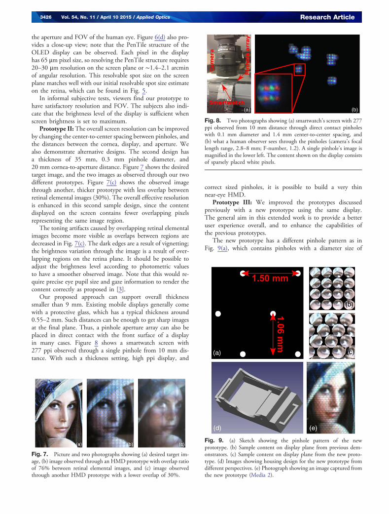
Prototype II: The overall screen resolution can be improvedby changing the center-to-center spacing between pinholes, andthe distances between the cornea, display, and aperture. Wealso demonstrate alternative designs. The second design hasa thickness of 35 mm, 0.3 mm pinhole diameter, and20 mm cornea-to-aperture distance. Figure 7 shows the desiredtarget image, and the two images as observed through our twodifferent prototypes. Figure 7(c) shows the observed imagethrough another, thicker prototype with less overlap betweenretinal elemental images (30%). The overall effective resolutionis enhanced in this second sample design, since the contentdisplayed on the screen contains fewer overlapping pixelsrepresenting the same image region.
The toning artifacts caused by overlapping retinal elementalimages become more visible as overlaps between regions aredecreased in Fig. 7(c). The dark edges are a result of vignetting;the brightness variation through the image is a result of over-lapping regions on the retina plane. It should be possible toadjust the brightness level according to photometric valuesto have a smoother observed image. Note that this would re-quire precise eye pupil size and gaze information to render thecontent correctly as proposed in [3].
Our proposed approach can support overall thicknesssmaller than 9 mm. Existing mobile displays generally comewith a protective glass, which has a typical thickness around0.55–2 mm. Such distances can be enough to get sharp imagesat the final plane. Thus, a pinhole aperture array can also beplaced in direct contact with the front surface of a displayin many cases. Figure 8 shows a smartwatch screen with277 ppi observed through a single pinhole from 10 mm dis-tance. With such a thickness setting, high ppi display, and
correct sized pinholes, it is possible to build a very thinnear-eye HMD.
Prototype III: We improved the prototypes discussedpreviously with a new prototype using the same display.The general aim in this extended work is to provide a betteruser experience overall, and to enhance the capabilities ofthe previous prototypes.
The new prototype has a different pinhole pattern as inFig. 9(a), which contains pinholes with a diameter size of
Fig. 7. Picture and two photographs showing (a) desired target im-age, (b) image observed through an HMD prototype with overlap ratioof 76% between retinal elemental images, and (c) image observedthrough another HMD prototype with a lower overlap of 30%.
Fig. 8. Two photographs showing (a) smartwatch’s screen with 277ppi observed from 10 mm distance through direct contact pinholeswith 0.1 mm diameter and 1.4 mm center-to-center spacing, and(b) what a human observer sees through the pinholes (camera’s focallength range, 2.8–8 mm; F-number, 1.2). A single pinhole’s image ismagnified in the lower left. The content shown on the display consistsof sparsely placed white pixels.
Fig. 9. (a) Sketch showing the pinhole pattern of the newprototype. (b) Sample content on display plane from previous dem-onstrators. (c) Sample content on display plane from the new proto-type. (d) Images showing housing design for the new prototype fromdifferent perspectives. (e) Photograph showing an image captured fromthe new prototype (Media 2).
3426 Vol. 54, No. 11 / April 10 2015 / Applied Optics Research Article
0.15 mm. Thus, it provides ×2.25 brightness than the previousstate. The center-to-center spacing of pinholes is 1.50 mm atthe vertical axis, and the horizontal row-to-row spacing be-tween pinholes is 1.06 mm in this configuration. The restof the distances were kept the same with previous prototypes.
The main intention in this type of design is to provide adenser pinhole array pattern, which decreases the visible effectof the pinhole pattern, and uses more pixels of the display. Sucha design requires a different arrangement of the content: in theprevious state, the visible part of the content on the displaythrough pinholes was as in Fig. 9(b); however, the new designrequires sample content as shown in Fig. 9(c).
Another improved aspect in this new prototype is a newhousing for the display as shown in Fig. 9(d). This design is3D printed in-house. Figure 9(e) shows a sample image fromthe new prototype, which is captured using the same camerawith the same settings as in Fig. 7.
We have conducted an informal subjective experiment onthe overall performance of the display with 31 participants;the participants were both shown static and moving scenes.Below you can find a summary of the negative feedback fromthe participants of this experiment.
• Overall resolution on retina found to be low as in the caseof all other lightfield displays.
• People with different eye prescriptions detected image dis-tortions, due to the shape of their eyes’ point spread function(PSF); however, the majority of people were able to perceiveclearly.
On the other hand, the positive feedback from the participantsof the experiment is as follows:
• Large FOV was well received.• People liked the idea of having a cost-effective, simple
solution without requiring much optics.• Nobody complained about the form factor or ergonomics
during the experiments.• Nobody complained about brightness during the experi-
ments. We believe housing helped in this case.
6. FUTURE WORK
A major trade-off in our proposal is the low light efficiency ofthe overall system. For our HMD prototypes, it is possible tohave larger pinhole diameters and give up some angular reso-lution, but overall system light efficiency would remainlow. Our prototype also does not directly address the accom-modation-vergence conflict. However, by overlapping retinalelemental images with higher percentages, it is possible to ad-dress both the accommodation-vergence conflict and the ton-ing effect on the image [1,3]. The amount of overlap could beincreased further using wavelength selective pinholes as in [5];thus a better representation of a lightfield can be achieved. The
pinhole pattern can be improved in our future prototypes;further analysis on sampling as discussed in [9] can help usto design different pinhole patterns to improve sampling onthe screen plane, and to overcome toning-related issues.Elliptical distortions (astigmatism) of a viewer’s eye can be cor-rected by modifying the content accordingly as in [4]. Anotheraspect of this type of display is dependency on the smartphone’scomputational capability; our aim is to stream content to thesmartphone to have more processing power for smarter contentgeneration, and to address some of the highlighted issues. Weintend to tackle these issues in the near future with new designsbased on this work. We believe this is a basis of a framework tobuild simple HMDs with too few optical components.
7. CONCLUSION
In this paper, we proposed a pinhole aperture array-based ap-proach to build a wide FOV and high optical angular resolutionHMD using mobile displays. We also demonstrated multipleproof-of-concept prototypes using a photo-plotted mask on atransparency film together with an existing mobile phone’s dis-play, or a smartwatch’s screen. We believe this is the simplestHMD setting proposed so far in the domain of computationalnear-eye display.
The authors thank Andrew Maimone for fruitful discussionsand useful insights.
REFERENCES1. D. Lanman and D. Luebke, “Near-eye light field displays,” ACM Trans.
Graph. 32, 220 (2013).2. A. Maimone and H. Fuchs, “Computational augmented reality eye-
glasses,” in IEEE International Symposium on Mixed andAugmented Reality (ISMAR) (IEEE, 2013), pp. 29–38.
3. A. Maimone, D. Lanman, K. Rathinavel, K. Keller, D. Luebke, and H.Fuchs, “Pinlight displays: wide field of view augmented reality eye-glasses using defocused point light sources,” in ACM SIGGRAPH2014 Emerging Technologies (ACM, 2014), p. 20.
4. F.-C. Huang, G. Wetzstein, B. A. Barsky, and R. Raskar, “Eyeglasses-free display: towards correcting visual aberrations with computationallight field displays,” ACM Trans. Graph. 33, 59 (2014).
5. K. Aksit, A. H. G. Niaki, E. Ulusoy, and H. Urey, “Super stereoscopytechnique for comfortable and realistic 3D displays,” Opt. Lett. 39,6903–6906 (2014).
6. R. Sprague, A. Zhang, L. Hendricks, T. O’Brien, J. Ford, E. Tremblay,and T. Rutherford, “Novel HMD concepts from the DARPA SCENICCprogram,” Proc. SPIE 8383, 838302 (2012).
7. W. Song, Y. Wang, D. Cheng, and Y. Liu, “Design of light field head-mounted display,” in International Optical Design Conference (OpticalSociety of America, 2014), paper ITh4A-3.
8. S. De Groot and J. Gebhard, “Pupil size as determined by adaptingluminance,” J. Opt. Soc. Am. 42, 492–495 (1952).
9. S. Dammertz and A. Keller, “Image synthesis by rank-1 lattices,” inMonte Carlo and Quasi-Monte Carlo Methods (Springer, 2008),pp. 217–236.
Research Article Vol. 54, No. 11 / April 10 2015 / Applied Optics 3427