Embed Size (px)
Citation preview
Sliding Mode and PID Control of a DualStage Actuator for Precision Positioning
Shingo Ito Juergen Steininger Georg Schitter
Automation and Control Institute (ACIN), Vienna University ofTechnology, Gusshausstrasse 27-29, 1040, Vienna, Austria(e-mail: {ito, juergen.steininger, schitter}@acin.tuwien.ac.at)
Abstract: Actuators composing dual stage actuation usually have different purposes andmechanisms to complement each other. Hence, they potentially have different types of controlchallenges to achieve high-precision motion performance. This paper presents the use of single-input single-output controllers to efficiently overcome the potential problems by selecting propercontrol techniques to each actuator. The setup is a low-stiffness dual stage actuator capableof positioning with nanometer resolution without additional vibration isolation. The systemconsists of a CD/DVD laser pickup and a linear motor with roller bearings, which suffer fromenvironmental vibrations and friction, respectively. By selecting and implementing a tamedPID controller for the pickup and a sliding mode controller for the linear motor, the dual stageactuator is able to move over 100mm with a maximum velocity of 0.34m/s and position witha static precision of ± 2.5 nm (peak-to-peak).
1. INTRODUCTION
In applications where high-precision positioning over along range is required, a single actuator may not be ableto achieve the desired performance. To satisfy the require-ments, a long-stroke coarse actuator can be combined witha short-stroke fine (high-precision) actuator as a dual stageactuator (DSA). This technique has been successfully ap-plied to many applications, such as optical disk drives(Chaghajerdi [2008]) and wafer scanners for lithography(Butler [2011]).
In order to control DSA systems, multi-input multi-output(MIMO) control design can be applied, since they canbe regarded as a system with at least multiple inputs.The MIMO control includes H2 control, H∞ control,µ-synthesis, and sliding mode control (SMC) (Hu et al.[1998], Al Mamun et al. [2003], Tai and Chen [2005],Nagamune et al. [2006]). These controls can guaranteethe stability and robustness of the overall system. Anotherstrategy to control DSA systems is to design single-inputsingle-output (SISO) controllers for the fine and coarseactuators in a certain configuration (Guo et al. [1999]).By using the SISO control design, the order of controllerscan be lower than that of MIMO (Semba et al. [1999]).More importantly, the SISO design has the freedom ofselecting the control design techniques individually for thefine actuator and the coarse actuator, whereas the MIMOusually applies same techniques to both. In fact, Herrmannet al. [2007] successfully applied discrete SMC to the fineactuator, while using proximate time-optimal control forthe coarse actuator in a hard disk drive (HDD).
In general, the fine actuator and the coarse actuator of aDSA have different actuation principles and mechanismsto complement each other. For example, a piezoelectricstage is mounted onto a gantry stage with ball screwsand DC servo motors to compensate for backlash and
friction (Lin et al. [2009]). A piezoelectric device is alsoinstalled as the fine actuator on a voice coil motor toincrease the control bandwidth in a HDD. In a waferscanner, short-stroke Lorentz actuators are used togetherwith linear motors, physically isolating disturbances suchas floor vibrations (Butler [2011]). Due to such multipleactuation principles potentially existing in a DSA system,it is natural that different types of control challengesarise individually for the fine actuator and the coarseactuator. To overcome such problems for high-precisionpositioning over a long range, the SISO control design canbe effectively applied by utilizing the freedom of controltechnique selection. In other words, the SISO design allowsthe user to pick proper tools to individually solve thedistinct control problems.
This paper presents a low-stiffness DSA, which is con-structed to achieve long-range positioning with nanometerresolution without extra vibration isolation (e.g. an opticaltable) (Ito et al. [2013]). This system consists of a laserpickup of a CD/DVD player as the fine actuator and alinear motor with roller bearings as the coarse actuator.For these actuators, controllers are individually designedto achieve high-speed high-precision positioning over along range.
The rest of this paper is organized as follows. Section 2introduces the DSA system. This system is modeled andits disturbances are analyzed in Section 3. Controllers aredesigned in Section 4. Section 5 presents experimentalresults, comparing performance of the SISO control designwith and without the individual control technique selec-tion. The paper is concluded in Section 6.
2. SYSTEM DESCRIPTION
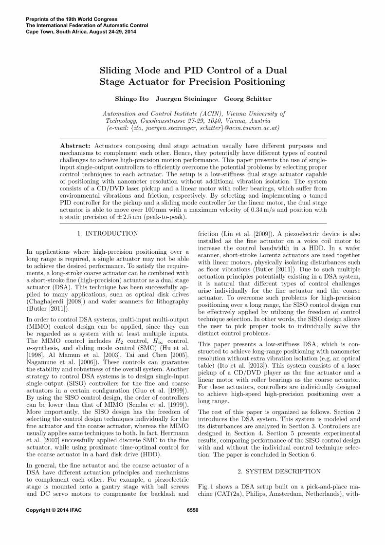
Fig. 1 shows a DSA setup built on a pick-and-place ma-chine (CAT(2a), Philips, Amsterdam, Netherlands), with-
Preprints of the 19th World CongressThe International Federation of Automatic ControlCape Town, South Africa. August 24-29, 2014
Copyright © 2014 IFAC 6550
Linear
motor
Detectors of
interferometer
Pickup and retroreflectors
Fig. 1. Photograph of the DSA setup.
out external vibration isolation such as an optical table.This machine has six linear motors, and one of them isused as the long-stroke coarse actuator of the DSA. Thelinear motor is guided by roller bearings and operatedby a servo driver in force control mode. As the fine ac-tuator, a Lorentz actuator in a laser pickup (SF-HD65,Sanyo, Osaka, Japan) is used and driven by a voltageamplifier. The actuation range of the fine actuator is lim-ited to approximately ± 1mm. To optically measure thefine actuator position, its objective lens is replaced by acube-corner retroreflector, and an interferometer (10899A,Agilent Technologies, San Francisco, USA) is mounted onthe platform for the real time control of the DSA. Theinterferometer has a resolution of 1.25 nm and detectsmovement up to 0.40m/s. An additional retroreflector ismounted on the coarse actuator to measure its positionwith a second interferometric detector. This second sensoris not used for the control, but for evaluation only.
The servo driver, the voltage amplifier and the interfer-ometers are all connected to a rapid control prototypingsystem (DS1005(CPU), DS5203(FPGA), DS2102(DAC),dSpace GmbH, Paderborn, Germany), where controllersare implemented running at a sampling frequency of20 kHz. This system is also used for data acquisition.
3. SYSTEM ANALYSIS
3.1 Dynamic model
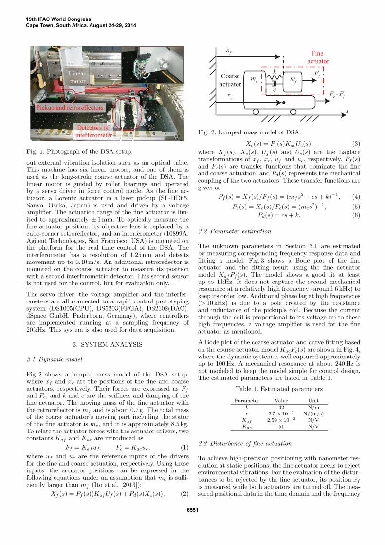
Fig. 2 shows a lumped mass model of the DSA setup,where xf and xc are the positions of the fine and coarseactuators, respectively. Their forces are expressed as Ff
and Fc, and k and c are the stiffness and damping of thefine actuator. The moving mass of the fine actuator withthe retroreflector is mf and is about 0.7 g. The total massof the coarse actuator’s moving part including the statorof the fine actuator is mc, and it is approximately 8.5 kg.To relate the actuator forces with the actuator drivers, twoconstants Kaf and Kac are introduced as
Ff = Kafuf , Fc = Kacuc, (1)
where uf and uc are the reference inputs of the driversfor the fine and coarse actuation, respectively. Using theseinputs, the actuator positions can be expressed in thefollowing equations under an assumption that mc is suffi-ciently larger than mf (Ito et al. [2013]):
Xf (s) = Pf (s)(KafUf (s) + Pd(s)Xc(s)), (2)
mc
mf
x
k
xf
xc
Ff
Fc - F
f
c
Fine
actuator
Coarse
actuator
Fig. 2. Lumped mass model of DSA.
Xc(s) = Pc(s)KacUc(s), (3)
where Xf (s), Xc(s), Uf (s) and Uc(s) are the Laplacetransformations of xf , xc, uf and uc, respectively. Pf (s)and Pc(s) are transfer functions that dominate the fineand coarse actuation, and Pd(s) represents the mechanicalcoupling of the two actuators. These transfer functions aregiven as
Pf (s) = Xf (s)/Ff (s) = (mfs2 + cs+ k)−1, (4)
Pc(s) = Xc(s)/Fc(s) = (mcs2)−1, (5)
Pd(s) = cs+ k. (6)
3.2 Parameter estimation
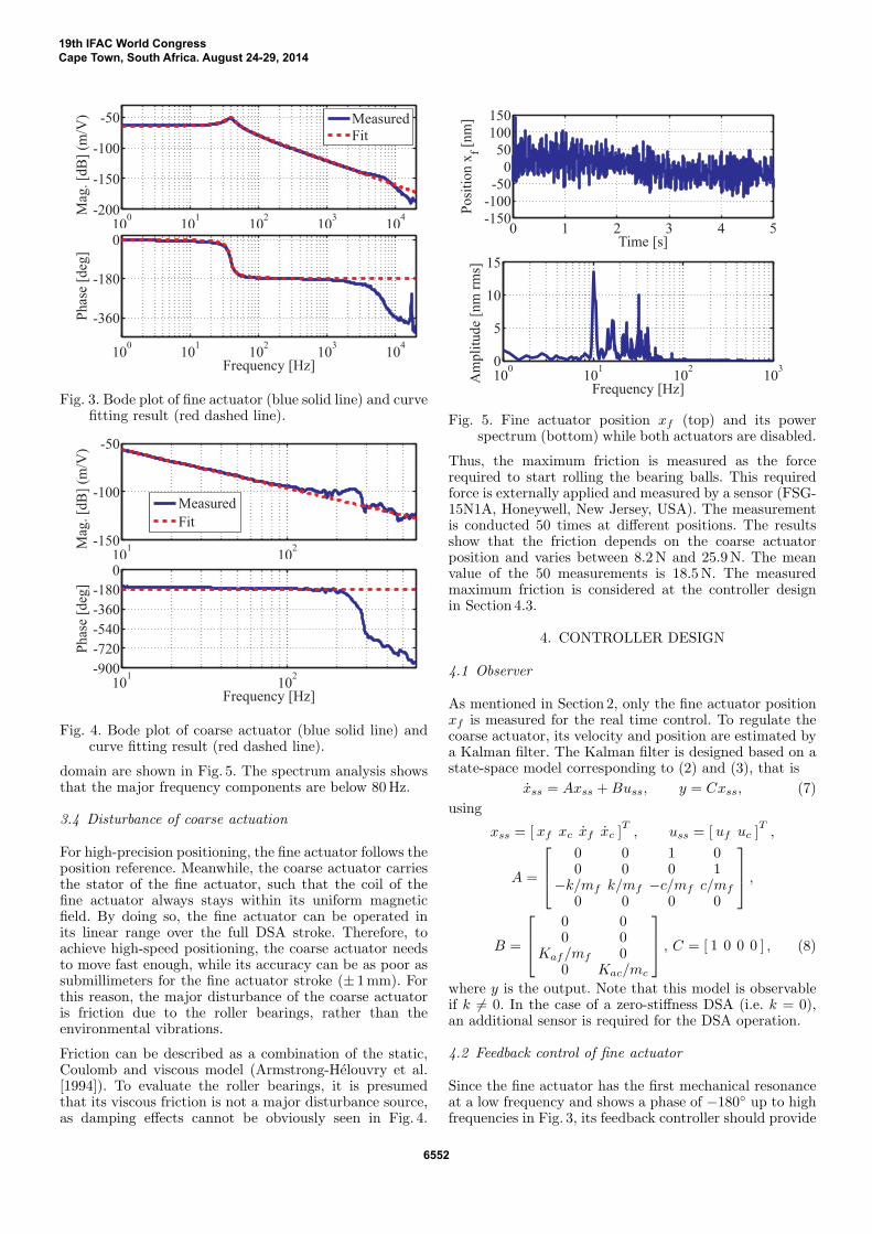
The unknown parameters in Section 3.1 are estimatedby measuring corresponding frequency response data andfitting a model. Fig. 3 shows a Bode plot of the fineactuator and the fitting result using the fine actuatormodel KafPf (s). The model shows a good fit at leastup to 1 kHz. It does not capture the second mechanicalresonance at a relatively high frequency (around 6 kHz) tokeep its order low. Additional phase lag at high frequencies(> 10 kHz) is due to a pole created by the resistanceand inductance of the pickup’s coil. Because the currentthrough the coil is proportional to its voltage up to thesehigh frequencies, a voltage amplifier is used for the fineactuator as mentioned.
A Bode plot of the coarse actuator and curve fitting basedon the course actuator modelKacPc(s) are shown in Fig. 4,where the dynamic system is well captured approximatelyup to 100Hz. A mechanical resonance at about 240Hz isnot modeled to keep the model simple for control design.The estimated parameters are listed in Table 1.
Table 1. Estimated parameters
Parameter Value Unit
k 42 N/mc 3.5× 10⁻² N/(m/s)
Kaf 2.59× 10⁻² N/VKac 51 N/V
3.3 Disturbance of fine actuation
To achieve high-precision positioning with nanometer res-olution at static positions, the fine actuator needs to rejectenvironmental vibrations. For the evaluation of the distur-bances to be rejected by the fine actuator, its position xf
is measured while both actuators are turned off. The mea-sured positional data in the time domain and the frequency
19th IFAC World CongressCape Town, South Africa. August 24-29, 2014
6551
100
101
102
103
104
-200
-150
-100
-50
Mag
. [d
B]
(m/V
)
Measured
Fit
100
101
102
103
104
-360
-180
0
Ph
ase
[deg
]
Frequency [Hz]
Fig. 3. Bode plot of fine actuator (blue solid line) and curvefitting result (red dashed line).
101
102
-150
-100
-50
Mag
. [d
B]
(m/V
)
Measured
Fit
101
102
-900
-720
-540
-360
-180
0
Ph
ase
[deg
]
Frequency [Hz]
Fig. 4. Bode plot of coarse actuator (blue solid line) andcurve fitting result (red dashed line).
domain are shown in Fig. 5. The spectrum analysis showsthat the major frequency components are below 80Hz.
3.4 Disturbance of coarse actuation
For high-precision positioning, the fine actuator follows theposition reference. Meanwhile, the coarse actuator carriesthe stator of the fine actuator, such that the coil of thefine actuator always stays within its uniform magneticfield. By doing so, the fine actuator can be operated inits linear range over the full DSA stroke. Therefore, toachieve high-speed positioning, the coarse actuator needsto move fast enough, while its accuracy can be as poor assubmillimeters for the fine actuator stroke (± 1mm). Forthis reason, the major disturbance of the coarse actuatoris friction due to the roller bearings, rather than theenvironmental vibrations.
Friction can be described as a combination of the static,Coulomb and viscous model (Armstrong-Helouvry et al.[1994]). To evaluate the roller bearings, it is presumedthat its viscous friction is not a major disturbance source,as damping effects cannot be obviously seen in Fig. 4.
0 1 2 3 4 5-150
-100
-50
0
50
100
150
Time [s]
Po
sit
ion
xf [
nm
]
100
101
102
103
0
5
10
15
Frequency [Hz]
Am
pli
tud
e [n
m r
ms]
Fig. 5. Fine actuator position xf (top) and its powerspectrum (bottom) while both actuators are disabled.
Thus, the maximum friction is measured as the forcerequired to start rolling the bearing balls. This requiredforce is externally applied and measured by a sensor (FSG-15N1A, Honeywell, New Jersey, USA). The measurementis conducted 50 times at different positions. The resultsshow that the friction depends on the coarse actuatorposition and varies between 8.2N and 25.9N. The meanvalue of the 50 measurements is 18.5N. The measuredmaximum friction is considered at the controller designin Section 4.3.
4. CONTROLLER DESIGN
4.1 Observer
As mentioned in Section 2, only the fine actuator positionxf is measured for the real time control. To regulate thecoarse actuator, its velocity and position are estimated bya Kalman filter. The Kalman filter is designed based on astate-space model corresponding to (2) and (3), that is
xss = Axss +Buss, y = Cxss, (7)
using
xss = [ xf xc xf xc ]T, uss = [ uf uc ]
T,
A =
0 0 1 00 0 0 1
−k/mf k/mf −c/mf c/mf
0 0 0 0
,
B =
0 00 0
Kaf/mf 00 Kac/mc
, C = [ 1 0 0 0 ] , (8)
where y is the output. Note that this model is observableif k = 0. In the case of a zero-stiffness DSA (i.e. k = 0),an additional sensor is required for the DSA operation.
4.2 Feedback control of fine actuator
Since the fine actuator has the first mechanical resonanceat a low frequency and shows a phase of −180◦ up to highfrequencies in Fig. 3, its feedback controller should provide
19th IFAC World CongressCape Town, South Africa. August 24-29, 2014
6552
100
101
102
103
-100
-50
0
50
Frequency [Hz]
Mag
nit
ud
e [d
B]
Measured
Simulated
Fig. 6. Measured (blue solid line) and simulated (reddashed line) sensitivity function of fine actuation.
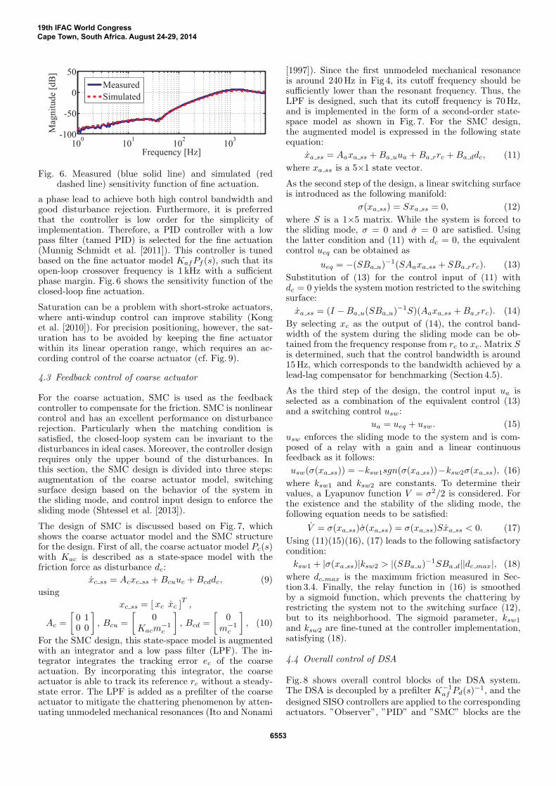
a phase lead to achieve both high control bandwidth andgood disturbance rejection. Furthermore, it is preferredthat the controller is low order for the simplicity ofimplementation. Therefore, a PID controller with a lowpass filter (tamed PID) is selected for the fine actuation(Munnig Schmidt et al. [2011]). This controller is tunedbased on the fine actuator model KafPf (s), such that itsopen-loop crossover frequency is 1 kHz with a sufficientphase margin. Fig. 6 shows the sensitivity function of theclosed-loop fine actuation.
Saturation can be a problem with short-stroke actuators,where anti-windup control can improve stability (Konget al. [2010]). For precision positioning, however, the sat-uration has to be avoided by keeping the fine actuatorwithin its linear operation range, which requires an ac-cording control of the coarse actuator (cf. Fig. 9).
4.3 Feedback control of coarse actuator
For the coarse actuation, SMC is used as the feedbackcontroller to compensate for the friction. SMC is nonlinearcontrol and has an excellent performance on disturbancerejection. Particularly when the matching condition issatisfied, the closed-loop system can be invariant to thedisturbances in ideal cases. Moreover, the controller designrequires only the upper bound of the disturbances. Inthis section, the SMC design is divided into three steps:augmentation of the coarse actuator model, switchingsurface design based on the behavior of the system inthe sliding mode, and control input design to enforce thesliding mode (Shtessel et al. [2013]).
The design of SMC is discussed based on Fig. 7, whichshows the coarse actuator model and the SMC structurefor the design. First of all, the coarse actuator model Pc(s)with Kac is described as a state-space model with thefriction force as disturbance dc:
xc ss = Acxc ss +Bcuuc +Bcddc, (9)
using
xc ss = [ xc xc ]T,
Ac =
[0 10 0
], Bcu =
[0
Kacm−1c
], Bcd =
[0
m−1c
], (10)
For the SMC design, this state-space model is augmentedwith an integrator and a low pass filter (LPF). The in-tegrator integrates the tracking error ec of the coarseactuation. By incorporating this integrator, the coarseactuator is able to track its reference rc without a steady-state error. The LPF is added as a prefilter of the coarseactuator to mitigate the chattering phenomenon by atten-uating unmodeled mechanical resonances (Ito and Nonami
[1997]). Since the first unmodeled mechanical resonanceis around 240Hz in Fig 4, its cutoff frequency should besufficiently lower than the resonant frequency. Thus, theLPF is designed, such that its cutoff frequency is 70Hz,and is implemented in the form of a second-order state-space model as shown in Fig. 7. For the SMC design,the augmented model is expressed in the following stateequation:
xa ss = Aaxa ss +Ba uua +Ba rrc +Ba ddc, (11)
where xa ss is a 5×1 state vector.
As the second step of the design, a linear switching surfaceis introduced as the following manifold:
σ(xa ss) = Sxa ss = 0, (12)
where S is a 1×5 matrix. While the system is forced tothe sliding mode, σ = 0 and σ = 0 are satisfied. Usingthe latter condition and (11) with dc = 0, the equivalentcontrol ueq can be obtained as
ueq = −(SBa u)−1(SAaxa ss + SBa rrc). (13)
Substitution of (13) for the control input of (11) withdc = 0 yields the system motion restricted to the switchingsurface:
xa ss = (I −Ba u(SBa u)−1S)(Aaxa ss +Ba rrc). (14)
By selecting xc as the output of (14), the control band-width of the system during the sliding mode can be ob-tained from the frequency response from rc to xc. Matrix Sis determined, such that the control bandwidth is around15Hz, which corresponds to the bandwidth achieved by alead-lag compensator for benchmarking (Section 4.5).
As the third step of the design, the control input ua isselected as a combination of the equivalent control (13)and a switching control usw:
ua = ueq + usw. (15)
usw enforces the sliding mode to the system and is com-posed of a relay with a gain and a linear continuousfeedback as it follows:
usw(σ(xa ss)) = −ksw1sgn(σ(xa ss))−ksw2σ(xa ss), (16)
where ksw1 and ksw2 are constants. To determine theirvalues, a Lyapunov function V = σ2/2 is considered. Forthe existence and the stability of the sliding mode, thefollowing equation needs to be satisfied:
V = σ(xa ss)σ(xa ss) = σ(xa ss)Sxa ss < 0. (17)
Using (11)(15)(16), (17) leads to the following satisfactorycondition:
ksw1 + |σ(xa ss)|ksw2 > |(SBa u)−1SBa d||dc max|, (18)
where dc max is the maximum friction measured in Sec-tion 3.4. Finally, the relay function in (16) is smoothedby a sigmoid function, which prevents the chattering byrestricting the system not to the switching surface (12),but to its neighborhood. The sigmoid parameter, ksw1
and ksw2 are fine-tuned at the controller implementation,satisfying (18).
4.4 Overall control of DSA
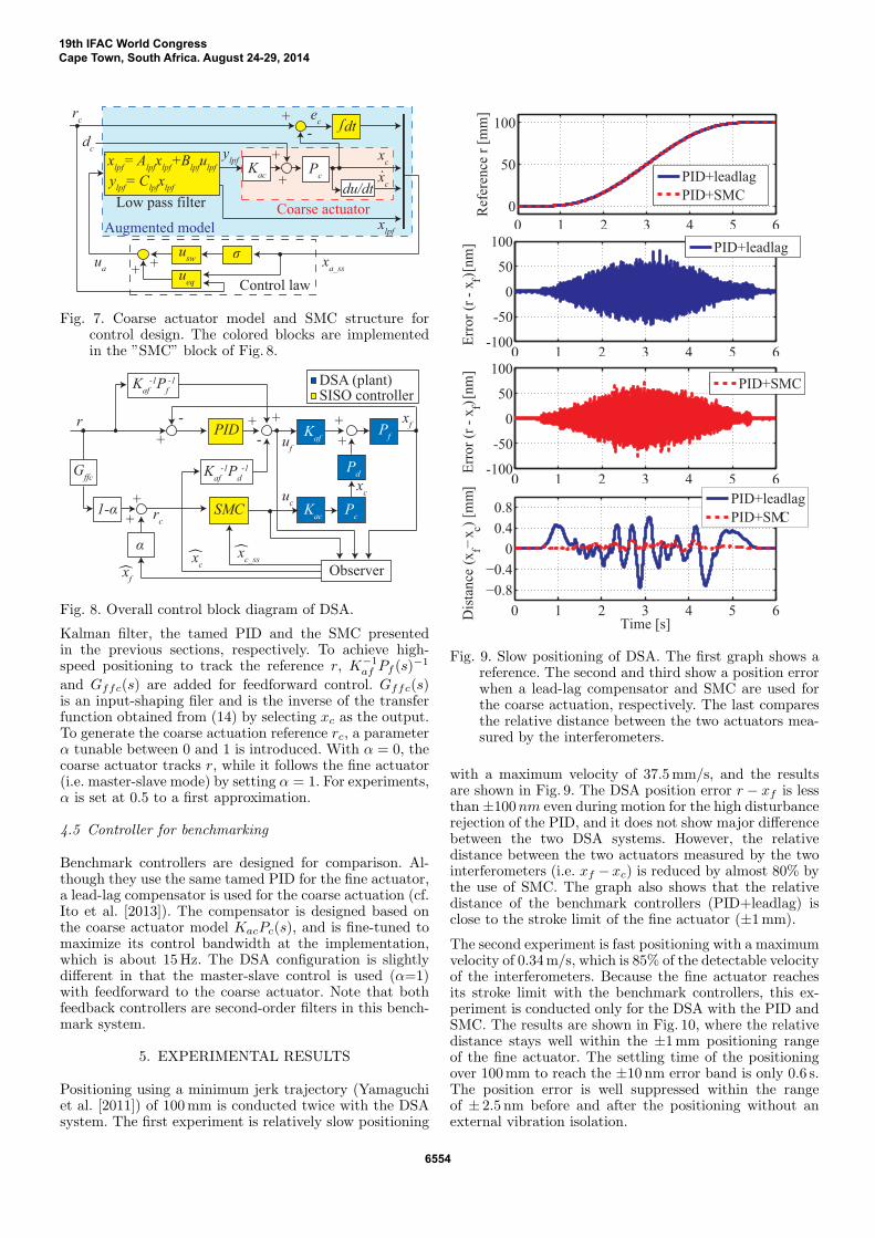
Fig. 8 shows overall control blocks of the DSA system.The DSA is decoupled by a prefilter K−1
af Pd(s)−1, and the
designed SISO controllers are applied to the correspondingactuators. ”Observer”, ”PID” and ”SMC” blocks are the
19th IFAC World CongressCape Town, South Africa. August 24-29, 2014
6553
rc
dt-+
+
ſ
ylpf
= Clpf
xlpf
xlpf
= Alpf
xlpf
+Blpf
ulpf
Coarse actuatorLow pass filter
dc
Pc
Kac
xc
du/dtx
c
·
xlpf
ylpf
usw
ueq
σ
Augmented model
xa_ss
+
+ +
ec
·
ua
Control law
Fig. 7. Coarse actuator model and SMC structure forcontrol design. The colored blocks are implementedin the ”SMC” block of Fig. 8.
Pf+
Pd
Pc
PID
Kaf
-1Pf-1
SMC
Observer
Kaf
-1Pd-1 G
ffc
Kac
Kaf
r
xc
xf
uf
uc
-
+
-
+ +
xc
xf
DSA (plant)SISO controller
+
xc_ss
+
+
1-α
α
rc
Fig. 8. Overall control block diagram of DSA.
Kalman filter, the tamed PID and the SMC presentedin the previous sections, respectively. To achieve high-speed positioning to track the reference r, K−1
af Pf (s)−1
and Gffc(s) are added for feedforward control. Gffc(s)is an input-shaping filer and is the inverse of the transferfunction obtained from (14) by selecting xc as the output.To generate the coarse actuation reference rc, a parameterα tunable between 0 and 1 is introduced. With α = 0, thecoarse actuator tracks r, while it follows the fine actuator(i.e. master-slave mode) by setting α = 1. For experiments,α is set at 0.5 to a first approximation.
4.5 Controller for benchmarking
Benchmark controllers are designed for comparison. Al-though they use the same tamed PID for the fine actuator,a lead-lag compensator is used for the coarse actuation (cf.Ito et al. [2013]). The compensator is designed based onthe coarse actuator model KacPc(s), and is fine-tuned tomaximize its control bandwidth at the implementation,which is about 15Hz. The DSA configuration is slightlydifferent in that the master-slave control is used (α=1)with feedforward to the coarse actuator. Note that bothfeedback controllers are second-order filters in this bench-mark system.
5. EXPERIMENTAL RESULTS
Positioning using a minimum jerk trajectory (Yamaguchiet al. [2011]) of 100mm is conducted twice with the DSAsystem. The first experiment is relatively slow positioning
0 1 2 3 4 5 6
0
50
100
Ref
eren
ce r
[m
m]
PID+leadlag
PID+SMC
0 1 2 3 4 5 6-100
-50
0
50
100
Err
or
(r -
x ) f [
nm
]
PID+leadlag
0 1 2 3 4 5 6-100
-50
0
50
100
Err
or
(r -
x ) f [
nm
]
PID+SMC
0 1 2 3 4 5 6
−0.8
−0.4
0
0.4
0.8
Time [s]
Dis
tan
ce (
xf−
x c) [m
m]
PID+leadlag
PID+SMC
Fig. 9. Slow positioning of DSA. The first graph shows areference. The second and third show a position errorwhen a lead-lag compensator and SMC are used forthe coarse actuation, respectively. The last comparesthe relative distance between the two actuators mea-sured by the interferometers.
with a maximum velocity of 37.5mm/s, and the resultsare shown in Fig. 9. The DSA position error r − xf is lessthan ±100nm even during motion for the high disturbancerejection of the PID, and it does not show major differencebetween the two DSA systems. However, the relativedistance between the two actuators measured by the twointerferometers (i.e. xf − xc) is reduced by almost 80% bythe use of SMC. The graph also shows that the relativedistance of the benchmark controllers (PID+leadlag) isclose to the stroke limit of the fine actuator (±1mm).
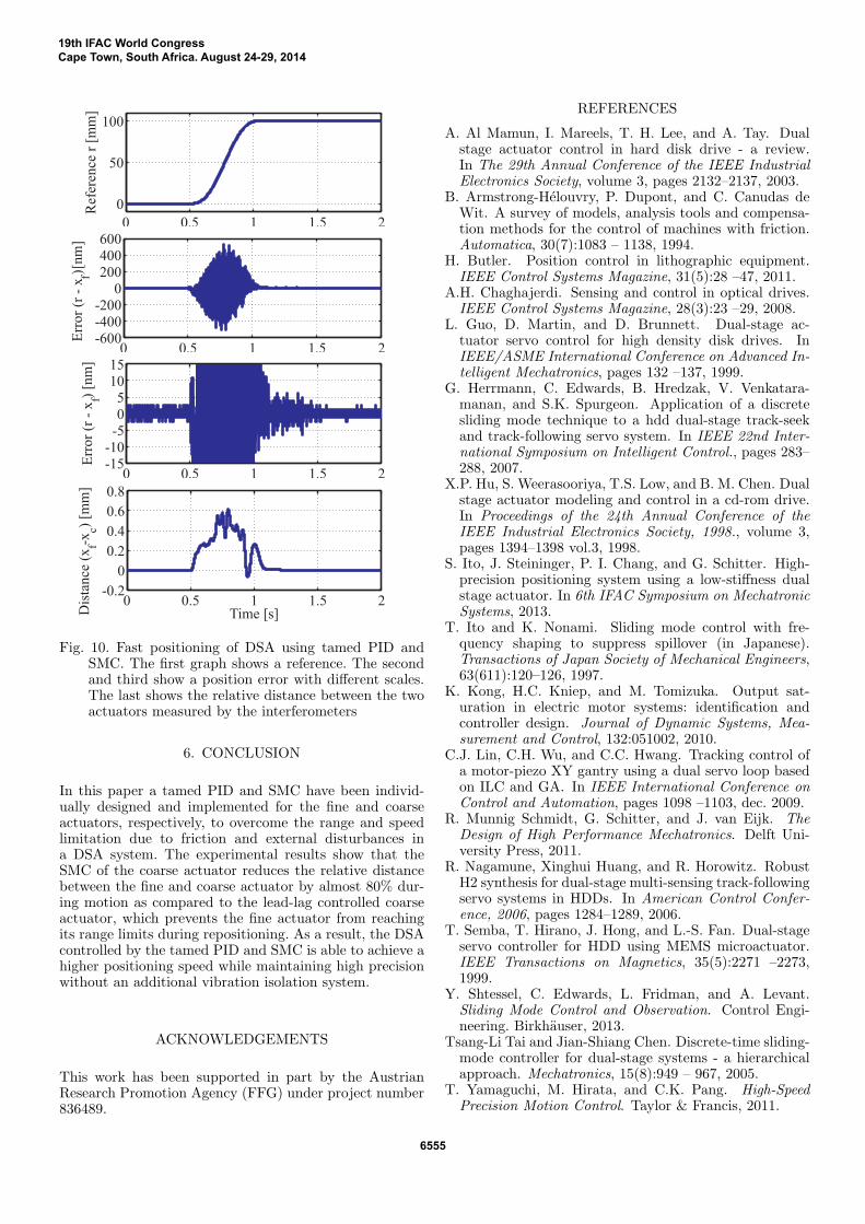
The second experiment is fast positioning with a maximumvelocity of 0.34m/s, which is 85% of the detectable velocityof the interferometers. Because the fine actuator reachesits stroke limit with the benchmark controllers, this ex-periment is conducted only for the DSA with the PID andSMC. The results are shown in Fig. 10, where the relativedistance stays well within the ±1mm positioning rangeof the fine actuator. The settling time of the positioningover 100mm to reach the ±10 nm error band is only 0.6 s.The position error is well suppressed within the rangeof ± 2.5 nm before and after the positioning without anexternal vibration isolation.
19th IFAC World CongressCape Town, South Africa. August 24-29, 2014
6554
0 0.5 1 1.5 2
0
50
100
Refe
ren
ce r
[m
m]
0 0.5 1 1.5 2-600
-400
-200
0
200
400
600
Err
or
(r -
x ) f [
nm
]
0 0.5 1 1.5 2-15
-10
-5
0
5
10
15
Err
or
(r -
xf)
[nm
]
0 0.5 1 1.5 2-0.2
0
0.2
0.4
0.6
0.8
Time [s]Dis
tan
ce (
xf-x
c)
[mm
]
Fig. 10. Fast positioning of DSA using tamed PID andSMC. The first graph shows a reference. The secondand third show a position error with different scales.The last shows the relative distance between the twoactuators measured by the interferometers
6. CONCLUSION
In this paper a tamed PID and SMC have been individ-ually designed and implemented for the fine and coarseactuators, respectively, to overcome the range and speedlimitation due to friction and external disturbances ina DSA system. The experimental results show that theSMC of the coarse actuator reduces the relative distancebetween the fine and coarse actuator by almost 80% dur-ing motion as compared to the lead-lag controlled coarseactuator, which prevents the fine actuator from reachingits range limits during repositioning. As a result, the DSAcontrolled by the tamed PID and SMC is able to achieve ahigher positioning speed while maintaining high precisionwithout an additional vibration isolation system.
ACKNOWLEDGEMENTS
This work has been supported in part by the AustrianResearch Promotion Agency (FFG) under project number836489.
REFERENCES
A. Al Mamun, I. Mareels, T. H. Lee, and A. Tay. Dualstage actuator control in hard disk drive - a review.In The 29th Annual Conference of the IEEE IndustrialElectronics Society, volume 3, pages 2132–2137, 2003.
B. Armstrong-Helouvry, P. Dupont, and C. Canudas deWit. A survey of models, analysis tools and compensa-tion methods for the control of machines with friction.Automatica, 30(7):1083 – 1138, 1994.
H. Butler. Position control in lithographic equipment.IEEE Control Systems Magazine, 31(5):28 –47, 2011.
A.H. Chaghajerdi. Sensing and control in optical drives.IEEE Control Systems Magazine, 28(3):23 –29, 2008.
L. Guo, D. Martin, and D. Brunnett. Dual-stage ac-tuator servo control for high density disk drives. InIEEE/ASME International Conference on Advanced In-telligent Mechatronics, pages 132 –137, 1999.
G. Herrmann, C. Edwards, B. Hredzak, V. Venkatara-manan, and S.K. Spurgeon. Application of a discretesliding mode technique to a hdd dual-stage track-seekand track-following servo system. In IEEE 22nd Inter-national Symposium on Intelligent Control., pages 283–288, 2007.
X.P. Hu, S. Weerasooriya, T.S. Low, and B. M. Chen. Dualstage actuator modeling and control in a cd-rom drive.In Proceedings of the 24th Annual Conference of theIEEE Industrial Electronics Society, 1998., volume 3,pages 1394–1398 vol.3, 1998.
S. Ito, J. Steininger, P. I. Chang, and G. Schitter. High-precision positioning system using a low-stiffness dualstage actuator. In 6th IFAC Symposium on MechatronicSystems, 2013.
T. Ito and K. Nonami. Sliding mode control with fre-quency shaping to suppress spillover (in Japanese).Transactions of Japan Society of Mechanical Engineers,63(611):120–126, 1997.
K. Kong, H.C. Kniep, and M. Tomizuka. Output sat-uration in electric motor systems: identification andcontroller design. Journal of Dynamic Systems, Mea-surement and Control, 132:051002, 2010.
C.J. Lin, C.H. Wu, and C.C. Hwang. Tracking control ofa motor-piezo XY gantry using a dual servo loop basedon ILC and GA. In IEEE International Conference onControl and Automation, pages 1098 –1103, dec. 2009.
R. Munnig Schmidt, G. Schitter, and J. van Eijk. TheDesign of High Performance Mechatronics. Delft Uni-versity Press, 2011.
R. Nagamune, Xinghui Huang, and R. Horowitz. RobustH2 synthesis for dual-stage multi-sensing track-followingservo systems in HDDs. In American Control Confer-ence, 2006, pages 1284–1289, 2006.
T. Semba, T. Hirano, J. Hong, and L.-S. Fan. Dual-stageservo controller for HDD using MEMS microactuator.IEEE Transactions on Magnetics, 35(5):2271 –2273,1999.
Y. Shtessel, C. Edwards, L. Fridman, and A. Levant.Sliding Mode Control and Observation. Control Engi-neering. Birkhauser, 2013.
Tsang-Li Tai and Jian-Shiang Chen. Discrete-time sliding-mode controller for dual-stage systems - a hierarchicalapproach. Mechatronics, 15(8):949 – 967, 2005.
T. Yamaguchi, M. Hirata, and C.K. Pang. High-SpeedPrecision Motion Control. Taylor & Francis, 2011.
19th IFAC World CongressCape Town, South Africa. August 24-29, 2014
6555