Embed Size (px)
Citation preview
2-61
Variations
Slide unit
Bearing
Slide
Ballbush-
ing
Model
Series CXWMBuilt-in shock absorber
Series CXWLBuilt-in shock absorber
Boresize
ø10
ø16
ø20
ø25
ø32
ø10
ø16
ø20
ø25
ø32
Stroke (mm)
(2)
(2)
(3)
(2)
(3)
(3)
25
(3)
50 75 100 125 150 175 200
Accessory
Note 1) Only E type reed switch is applicable as an auto switch when mounting a housing of ø10.Note 2) The shock absorbers are to be mounted on the both sides for the 25-stroke of
Series CXWM10 to 25.Note 3) The shock absorber is to be mounted on one side of the plate for the 25-stroke of
Series CXWM20, CXWM32, CXWL32 and 50-stroke of Series CXWM32.Plat
e m
ount
ing
(1)
(1)
Mountingof autoswitch
Page
2-66
2-91
With
end
lock
Shock
abs
orbe
r
Adjusti
ng b
olt
Housin
g mou
nting
Slide UnitSeries CXWM/CXWL Slide bearing/CXWM: ø10, ø16, ø20, ø25, ø32Ball bushing bearing/CXWL: ø10, ø16, ø20, ø25, ø32
Provided with shock absorbers to absorb impact and noise.The slide unit can absorb energy in a wide range, in high-speed, low-load applications to low-speed, high-load applications, without requiring adjustments.
Ensures high positional accuracyA high level of positional accuracy can be attained because the two parallel piston rods prevent the rods from rotating, and the workpiece mounting surface and the parallelism of the piston rods are made highly precise.
Mountable on the housing or on the plate.The slide unit can be mounted on the housing or on the plate, depending on the application. It can also be bolted from the bottom or from the top. The piping can be fitted to the port in any of the three positions, according to how the unit is mounted.
Auto switches can be installed.Smooth operation and high thrust.
<Affixing the plate>
<Affixing the housing>

2-62
2-63
Precautions
qDo not expose the shock absorber to machining oil, water, or dust.
The RB series cannot be used under conditions in which fluids such as machining oil or water are present in atomized form or come in direct contact with the piston rod, or in which dust could adhere to the piston rod. Such conditions would cause malfunction.
wDo not operate the shock absorber in an environment that poses the risk of corrosion.
The shock absorber could rust if used in an environment that poses the risk of corrosion. Refer to the respective construction drawing for type of material that is used in the shock absorber.
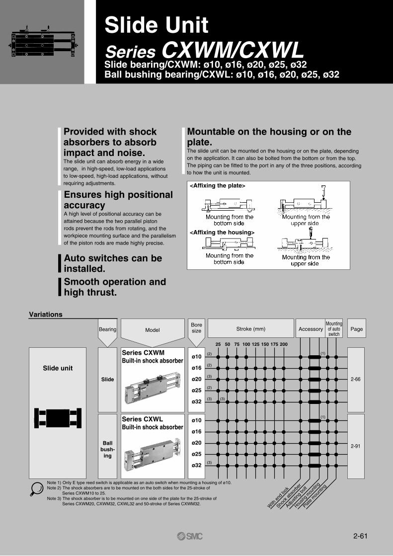
eTighten the retaining nuts to the torque values given in the table below.
rDo not scratch the sliding portion of the piston rod or the outside threads of the outer tube.
Do not scratch or gouge the sliding portion of the piston rod or the outside threads of the outer tube by striking it with an object, squeezing it, or by forcefully wedging a set screw in it. Failure to observe this precaution could damage the seals, which could lead to oil leakage and malfunction. Furthermore, scratches or gouges on the outside threads of the outer tube could prevent the shock absorber from being mounted onto the frame, or its internal components could deform, leading to a malfunction.
tNever turn the screw on the bottom of the body (it is not an adjustment screw), as this will cause oil leakage.
yMake sure that the retaining nut is not loose. The shock absorber could become damaged if it is used in a loose
state.uPay attention to any abnormal impact sounds or vibrations. If the impact sounds or vibrations have become abnormally high, the
shock absorber may have reached the end of its service life. If this is the case, replace the shock absorber. If use is continued in this state, it could damage the equipment to which the shock absorber is mounted.
qDo not use a 3 position solenoid valve. Avoid using this cylinder in combination with a 3 position solenoid
valve (particularly the closed center metal seal style). If air pressure becomes sealed inside the port of the side that contains the lock mechanism, the lock will not engage. Even if the lock is engaged at first, the air that leaks from the solenoid valve could enter the cylinder and cause the lock to disengage as time elapses.
wBefore starting, make sure to supply air to the retraction side to provide back pressure.
Failure to do so could prevent the lock from disengaging. It is dangerous to supply air to the extension side when the air in the cylinder has been discharged, as the cylinder could operate suddenly.
eDisengage the lock before installing or adjusting the cylinder.
The lock could become damaged if the cylinder is installed with its lock engaged.
rOperate the speed controller under meter-out control. If operated under meter-in control, the lock might not disengage.tAdjust the stroke within the range of the slotted hole of the lock
finger. As the hole for mounting the lock finger is slotted, the lock finger
may be adjusted and mounted in accordance with the adjustment amount of the adjustment bolt. The adjustment amount of the adjustment bolt is ±2mm (±1mm for each side).
yRegarding manual disengagement Insert a phillips screwdriver through the lock finger hole to push the
lock piston down and slide it in the unlocking direction. When doing so, take precautions to prevent your fingers or hands from getting caught between the housing plate and the lock.
Precautions for handling the end lock mechanism
Precautions for handling the shock absorberqTake precautions to prevent your fingers or hands from getting caught between the plate and the housing.
Exercise extreme caution when the cylinder is operating, to prevent injury to your fingers or hands.
qMake sure that the cylinder mounting surface is flat (a flatness of 0.05 or less {reference value}).
If it is not flat, it could lead to a malfunction.wMake sure not to scratch or gouge the cylinder mounting
surface. Be aware that if the flatness of the housing mounting surface or the
mounting surface of the plates on both sides is affected, it could lead to a malfunction.
eBe careful not to twist the two piston rods. If the piston rods are twisted or bent when mounting the housing, the
operating resistance could become abnormally high or the bearings could wear prematurely, leading to reduced accuracy or air leakage.
rConsider reinforcing the plates. When the cylinder is mounted on the housing, and the plates are used for
high-speed operation or used as a pusher, use a connector plate to bridge both plates. Failure to do so could cause the snap ring to become detached or the set screws to shift, causing the plates to fall off.
Warning
Caution
Caution
Caution
Model of shock absorbers
Applicable slide unit
Thread O.D. (mm)
Thread prepared hole size (mm)
Nut mounting torqueNm
RB0805
M8 X 1.0
1.67
ø7.1
CXWM -251016
+0.10
RB1006
M10 X 1.0
3.14
ø9.1
CXWM -252025
+0.10
RB1411
M14 X 1.5
10.8
ø12.7
CXWM32-25,50
CXWL32-25
+0.10
Precautions Series CX
2-64
Series CXPrior to Use
CXW10-25stroke0.40
0.35
0.30
0.25
0.20
Sta
rtin
g pr
essu
re (
MP
a)
Sta
rtin
g pr
essu
re (
MP
a)
Sta
rtin
g pr
essu
re (
MP
a)
1.25 1.50 1.75 2.0
Moment (Nm)
CXW20-25stroke
0.40
0.35
0.30
0.25
0.20
6.5 7.0 7.5 8.0
CXW25-25stroke0.40
0.35
0.30
0.25
0.20
9.0 10.0 11.0 12.0
CXW32-25stroke0.40
0.35
0.30
0.25
0.20
20.0 22.0 24.0 26.0
CXW16-25stroke0.40
0.35
0.30
0.25
0.20
3.5 4.0 4.5 5.0
Moment (Nm) Moment (Nm)
Moment (Nm)Moment (Nm)
Sta
rtin
g pr
essu
re (
MP
a)
Sta
rtin
g pr
essu
re (
MP
a)
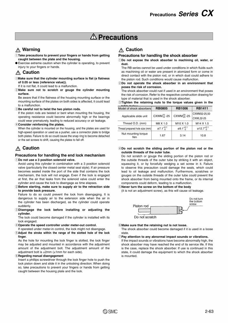
Comparison on the starting pressure by the moment (Reference data for selection a slide bearing or a ball bushing bearing)
Bore size (mm)
CXWM
CXWL
0.108
0.108
ø10
0.549
0.549
ø16
0.809
0.809
ø20
1.029
1.201
ø25
2.695
2.695
ø32Allowable moment (M2) (Nm)
Note) M2 is steady regardless of the strokes.
CMWM (Slide bearing)
CXWL (Ball bushing bearing)Comparison on the starting pressure with the load mounted and the moment addedNote) The diagram below does not show the
allowable moment. It compares the starting pressure of the slide bearing to that of the ball bushing when the load of the moment is applied to the bearing.
Maximum allowable moment/ CXWM, CXWLOperate within the operating range and under the allowable moment indicated in the table below.
Allowable kinetic energyOperate at a load mass and cylinder speed within the range given in the diagram below. To adjust the cylinder speed, use a speed controller.
Allowable kinetic energy of the slide unitLoad weight and cylinder speed should be within the
range indicated in the graph below.
2-65
Without auto switch/
Plate mounting style with auto switch
Housing mounting style with auto switch
Plate mounting style with auto switch
Housing mounting style with auto switch
CXW
CDPXW S ·······Table 1
CDBXW M ·······Table 2
CDPXW S ·······Table 1
CDBXW M ·······Table 2
M L
M L
M L
M L
M L
Series CXW
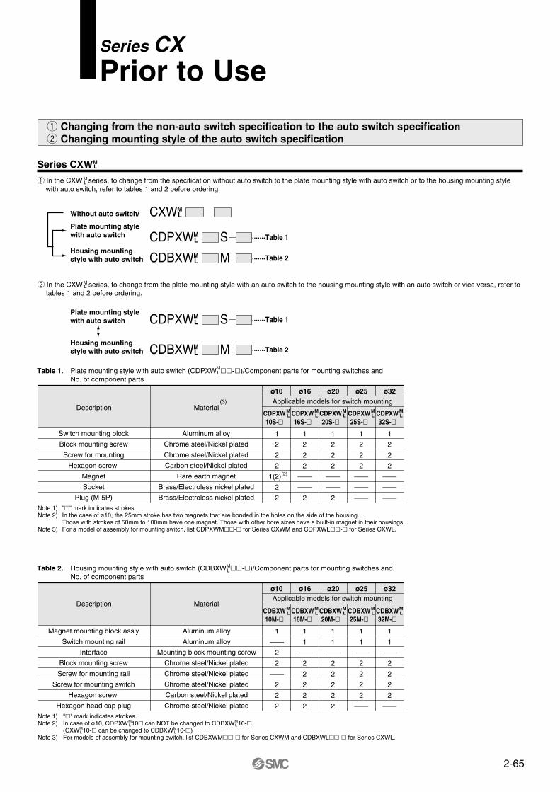
q In the CXW series, to change from the specification without auto switch to the plate mounting style with auto switch or to the housing mounting style with auto switch, refer to tables 1 and 2 before ordering.
w In the CXW series, to change from the plate mounting style with an auto switch to the housing mounting style with an auto switch or vice versa, refer to tables 1 and 2 before ordering.
M L
M L
M L
Series CXPrior to Use
q Changing from the non-auto switch specification to the auto switch specification w Changing mounting style of the auto switch specification
Table 1. Plate mounting style with auto switch (CDPXW -)/Component parts for mounting switches and No. of component parts
Description Material
ø10 ø16 ø20 ø25 ø32Applicable models for switch mounting
Switch mounting block
Block mounting screw
Screw for mounting
Hexagon screw
Magnet
Socket
Plug (M-5P)
Aluminum alloy
Chrome steel/Nickel plated
Chrome steel/Nickel plated
Carbon steel/Nickel plated
Rare earth magnet
Brass/Electroless nickel plated
Brass/Electroless nickel plated
1
2
2
2
1(2)
2
2
1
2
2
2
—
—
2
1
2
2
2
—
—
2
1
2
2
2
—
—
—
1
2
2
2
—
—
—Note 1) "" mark indicates strokes.Note 2) In the case of ø10, the 25mm stroke has two magnets that are bonded in the holes on the side of the housing.
Those with strokes of 50mm to 100mm have one magnet. Those with other bore sizes have a built-in magnet in their housings. Note 3) For a model of assembly for mounting switch, list CDPXWM- for Series CXWM and CDPXWL- for Series CXWL.
CDPXW10S-
ML CDPXW
16S-
ML CDPXW
20S-
ML CDPXW
25S-
ML CDPXW
32S-
ML
Table 2. Housing mounting style with auto switch (CDBXW -)/Component parts for mounting switches and No. of component parts
ø10 ø16 ø20 ø25 ø32
Magnet mounting block ass'y
Switch mounting rail
Interface
Block mounting screw
Screw for mounting rail
Screw for mounting switch
Hexagon screw
Hexagon head cap plug
Aluminum alloy
Aluminum alloy
Mounting block mounting screw
Chrome steel/Nickel plated
Chrome steel/Nickel plated
Chrome steel/Nickel plated
Carbon steel/Nickel plated
Chrome steel/Nickel plated
1
—
2
2
—
2
2
2
1
1
—
2
2
2
2
2
1
1
—
2
2
2
2
2
1
1
—
2
2
2
2
—
1
1
—
2
2
2
2
—Note 1) "" mark indicates strokes.Note 2) In case of ø10, CDPXW 10 can NOT be changed to CDBXW 10-.
(CXW 10- can be changed to CDBXW 10-)Note 3) For models of assembly for mounting switch, list CDBXWM- for Series CXWM and CDBXWL- for Series CXWL.
CDBXW10M-
ML
ML
ML
ML
ML
CDBXW16M-
ML
ML
CDBXW20M-
ML CDBXW
25M-
ML CDBXW
32M-
ML
(3)
(2)
ML
Description MaterialApplicable models for switch mounting
2-66
CXWM
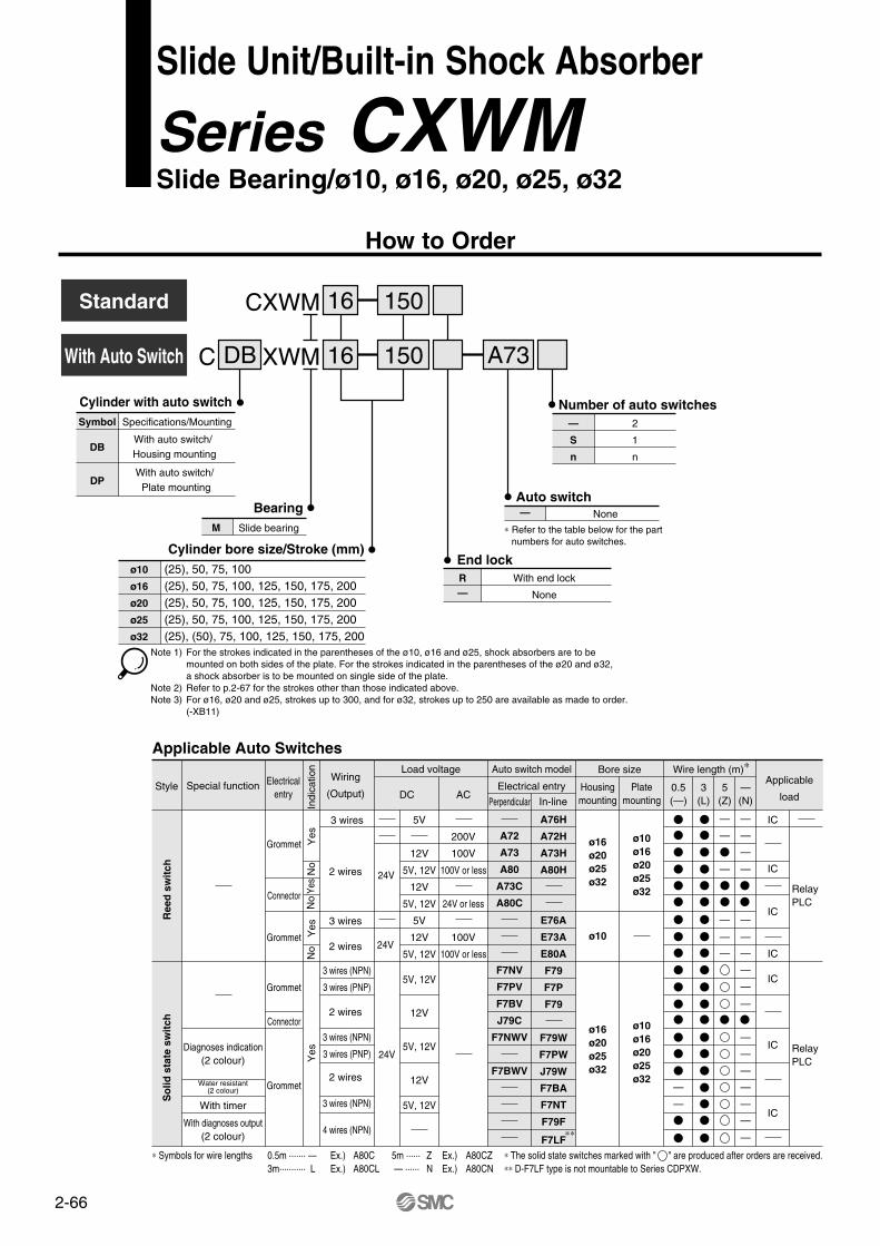
C XWMWith Auto Switch
Standard 16
16
Cylinder with auto switch
∗ Refer to the table below for the partnumbers for auto switches.
Number of auto switches—
S
n
2
1
n
Auto switch— None
150
150 A73DB
Symbol
DB
DP
Specifications/Mounting
With auto switch/ Housing mounting
BearingM Slide bearing
Cylinder bore size/Stroke (mm)ø10
ø16
ø20
ø25
ø32
(25), 50, 75, 100(25), 50, 75, 100, 125, 150, 175, 200(25), 50, 75, 100, 125, 150, 175, 200(25), 50, 75, 100, 125, 150, 175, 200(25), (50), 75, 100, 125, 150, 175, 200
End lockR—
With end lock
None
Note 1) For the strokes indicated in the parentheses of the ø10, ø16 and ø25, shock absorbers are to be mounted on both sides of the plate. For the strokes indicated in the parentheses of the ø20 and ø32, a shock absorber is to be mounted on single side of the plate.
Note 2) Refer to p.2-67 for the strokes other than those indicated above.Note 3) For ø16, ø20 and ø25, strokes up to 300, and for ø32, strokes up to 250 are available as made to order.
(-XB11)
Applicable Auto Switches
Ree
d s
wit
chS
olid
sta
te s
wit
ch
Special functionStyle
Diagnoses indication(2 colour)
Water resistant(2 colour)
With timer
With diagnoses output(2 colour)
Electricalentry
Grommet
Connector
Grommet
Grommet
Connector
Grommet
Indi
catio
n Y
esY
esY
esYe
s
Wiring
(Output)
3 wires
2 wires
3 wires
2 wires
2 wires
3 wires (NPN)
3 wires (PNP)
3 wires (NPN)
3 wires (NPN)
4 wires (NPN)
3 wires (PNP)
2 wires
Load voltage Auto switch model
DC
24V
24V
24V
5V
12V
5V, 12V
12V
5V, 12V
5V
12V
5V, 12V
5V, 12V
12V
5V, 12V
12V
5V, 12V
AC
200V
100V
100V or less
24V or less
100V
100V or less
Electrical entry
A72
A73
A80
A73C
A80C
F7NV
F7PV
F7BV
J79C
F7NWV
F7BWV
A76H
A72H
A73H
A80H
E76A
E73A
E80A
F79
F7P
F79
F79W
F7PW
J79W
F7BA
F7NT
F79F
F7LF
Bore size
Housingmounting
ø16ø20ø25ø32
ø10
Platemounting
ø10ø16ø20ø25ø32
ø16ø20ø25ø32
ø10ø16ø20ø25ø32
Wire length (m)∗
0.5(—)
3(L)
5(Z)
—(N)
Applicable
load
IC
IC
IC
IC
IC
IC
IC
RelayPLC
RelayPLC
∗∗
With auto switch/ Plate mounting
∗ Symbols for wire lengths 0.5m ······· — Ex.) A80C 5m ······ Z Ex.) A80CZ ∗ The solid state switches marked with " " are produced after orders are received.3m··········· L Ex.) A80CL — ······ N Ex.) A80CN ∗∗ D-F7LF type is not mountable to Series CDPXW.
No
No
No
Perpendicular In-line
— —
— —
— —
—
—
—
—
—
—
—
—
—
—
—
—
—
—
—
—
—
—
—
Slide Unit/Built-in Shock Absorber
Series CXWM Slide Bearing/ø10, ø16, ø20, ø25, ø32
How to Order
∗ "-X138" has a stroke adjustable range of 12.5mm on one side.
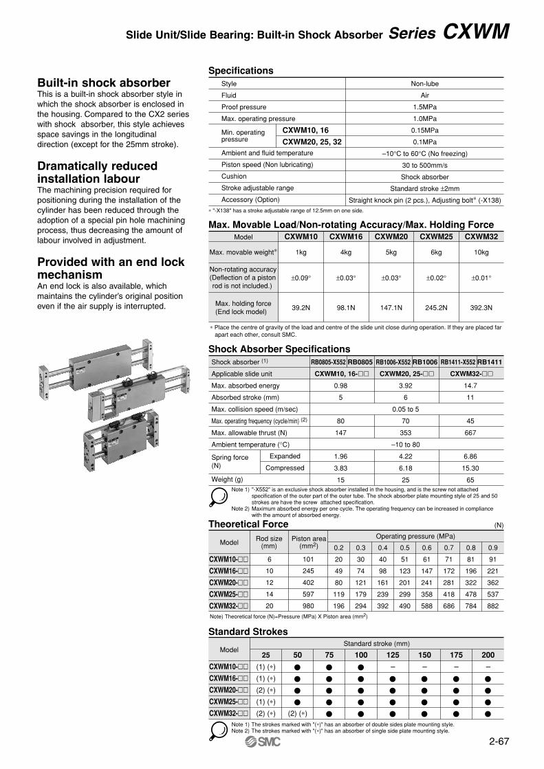
Specifications
CXWM10, 16
CXWM20, 25, 32
Style
Fluid
Proof pressure
Max. operating pressure
Min. operatingpressure
Ambient and fluid temperature
Piston speed (Non lubricating)
Cushion
Stroke adjustable range
Accessory (Option)
Non-lube
Air
1.5MPa
1.0MPa
0.15MPa
0.1MPa
–10°C to 60°C (No freezing)
30 to 500mm/s
Shock absorber
Standard stroke ±2mm
Straight knock pin (2 pcs.), Adjusting bolt∗ (-X138)
∗ Place the centre of gravity of the load and centre of the slide unit close during operation. If they are placed far apart each other, consult SMC.
Max. Movable Load/Non-rotating Accuracy/Max. Holding ForceCXWM10
1kg
±0.09°
39.2N
CXWM16
4kg
±0.03°
98.1N
CXWM20
5kg
±0.03°
147.1N
CXWM25
6kg
±0.02°
245.2N
CXWM32
10kg
±0.01°
392.3N
Model
Max. movable weight∗
Non-rotating accuracy(Deflection of a pistonrod is not included.)
Max. holding force(End lock model)
Note 1) "-X552" is an exclusive shock absorber installed in the housing, and is the screw not attached specification of the outer part of the outer tube. The shock absorber plate mounting style of 25 and 50 strokes are have the screw attached specification.
Note 2) Maximum absorbed energy per one cycle. The operating frequency can be increased in compliance with the amount of absorbed energy.
Shock Absorber Specifications
Expanded
Compressed
Shock absorber (1)
Applicable slide unit
Max. absorbed energy
Absorbed stroke (mm)
Max. collision speed (m/sec)
Max. operating frequency (cycle/min) (2)
Max. allowable thrust (N)
Ambient temperature (°C)
Spring force(N)
Weight (g)
RB0805-X552 RB0805
0.98
5
80
147
1.96
3.83
15
CXWM10, 16-
RB1006-X552 RB1006
3.92
6
0.05 to 5
70
353
–10 to 80
4.22
6.18
25
CXWM20, 25-
RB1411-X552 RB1411
14.7
11
45
667
6.86
15.30
65
CXWM32-
Note) Theoretical force (N)=Pressure (MPa) X Piston area (mm2)
Theoretical Force (N)
Model Rod size(mm)
Piston area(mm2)
6
10
12
14
20
101
245
402
597
980
Operating pressure (MPa)
0.2
20
49
80
119
196
0.3
30
74
121
179
294
0.4
40
98
161
239
392
0.5
51
123
201
299
490
0.6
61
147
241
358
588
0.7
71
172
281
418
686
0.8
81
196
322
478
784
0.9
91
221
362
537
882
Note 1) The strokes marked with "(∗)" has an absorber of double sides plate mounting style.Note 2) The strokes marked with "(∗)" has an absorber of single side plate mounting style.
Standard StrokesStandard stroke (mm)
25
(1) (∗)
(1) (∗)
(2) (∗)
(1) (∗)
(2) (∗)
50
(2) (∗)
75 100 125
–
150
–
175
–
200
–
CXWM10-CXWM16-CXWM20-CXWM25-CXWM32-
Model
CXWM10-CXWM16-CXWM20-CXWM25-CXWM32-
2-67
Built-in shock absorberThis is a built-in shock absorber style in which the shock absorber is enclosed in the housing. Compared to the CX2 series with shock absorber, this style achieves space savings in the longitudinal direction (except for the 25mm stroke).
Dramatically reduced installation labourThe machining precision required for positioning during the installation of the cylinder has been reduced through the adoption of a special pin hole machining process, thus decreasing the amount of labour involved in adjustment.
Provided with an end lock mechanismAn end lock is also available, which maintains the cylinder’s original position even if the air supply is interrupted.
Slide Unit/Slide Bearing: Built-in Shock Absorber Series CXWM
2-68
Series CXWM
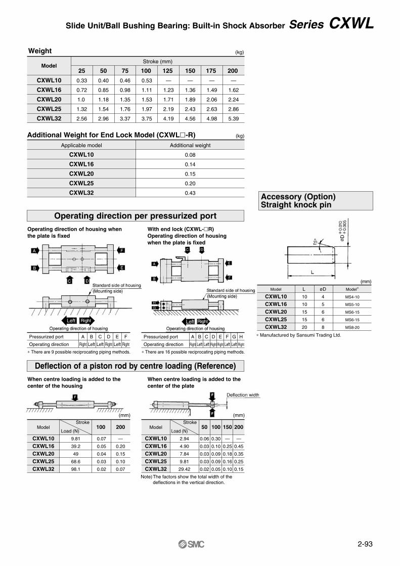
Weight (kg)
(kg)
Model
CXWM10
CXWM16
CXWM20
CXWM25
CXWM32
25
0.28
0.46
0.69
0.95
2.01
50
0.35
0.59
0.87
1.17
2.38
75
0.42
0.72
1.03
1.38
2.77
Stroke (mm)
100
0.49
0.85
1.22
1.60
3.16
125
—
0.98
1.40
1.82
3.56
150
—
1.11
1.58
2.03
3.94
175
—
1.24
1.75
2.31
4.34
200
—
1.37
1.93
2.47
4.72
Pressurized port
Operating direction
Additional Weight for End Lock Model (CXWM-R)Applicable model
CXWM10
CXWM16
CXWM20
CXWM25
CXWM32
Additional weight
0.08
0.14
0.15
0.20
0.43
Operating direction per pressurized port
Operating direction of the housing when theplate part is fixed
Pressurized port
Operating direction
A
Right
B
Left
C
Left
D
Right
E
Left
F
Right
With end lock (CXWM-R)Operating direction of the housing whenthe plate part is fixed
∗ There are 9 possible reciprocating piping methods.
A
Right
B
Left
C
Left
D
Right
E
Right
F
Left
G
Left
H
Right
∗ There are 16 possible reciprocating piping methods.
Deflection of the piston rod by center loading (Reference)
When centre loading is applied to the middle of the housing
(mm) (mm)
Model
CXWM10CXWM16CXWM20CXWM25CXWM32
Stroke Stroke
Load (N)
9.81
39.2
49
58.8
98.1
100
0.07
0.05
0.04
0.02
0.02
200 50 100 150 200
—
0.20
0.15
0.08
0.07
Load (N)Model
CXWM10CXWM16CXWM20CXWM25CXWM32
∗ Manufactured by Sansumi Trading Ltd.
When centre loading is applied to the middleof the plate
2.94
4.90
7.84
9.81
29.42
0.06
0.03
0.03
0.03
0.02
0.30
0.10
0.09
0.09
0.05
—
0.25
0.18
0.16
0.10
—
0.45
0.35
0.25
0.15
Note) The factors are the total widths of deflectionsin the vertical direction.
Accessory (Option) Straight knock pin
(mm)
ModelCXWM10CXWM16CXWM20CXWM25CXWM32
L1010151520
øD45668
Model∗
MS4-10MS5-10MS6-15MS6-15MS8-20
2-69
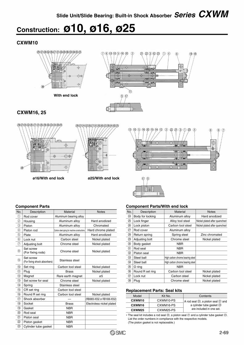
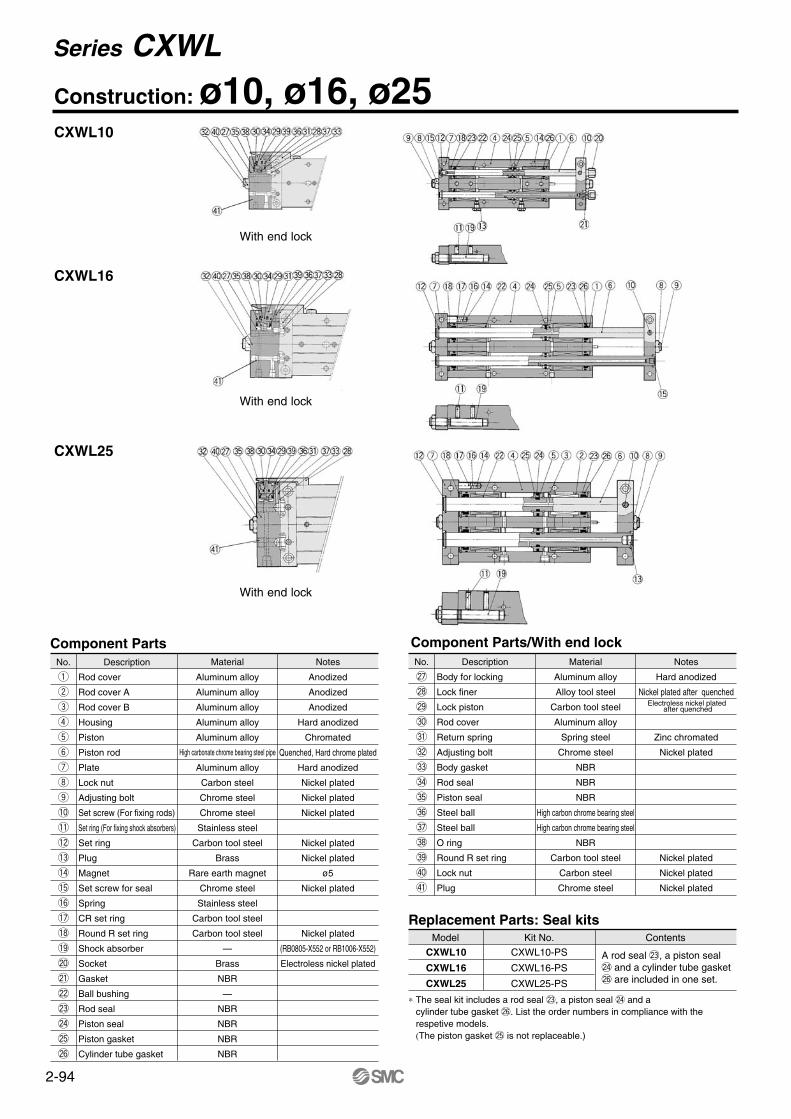
Component PartsNo.
q
w
e
r
t
y
u
i
o
!0
!1
!2
!3
!4
!5
!6
!7
!8
!9
@0
@1
@2
@3
Description Material
Aluminum bearing alloy
Aluminum alloy
Aluminum alloy
Carbon steel piping for machine constructions
Aluminum alloy
Carbon steel
Chrome steel
Chrome steel
Stainless steel
Carbon tool steel
Brass
Rare earth magnet
Chrome steel
Stainless steel
Carbon tool steel
Carbon tool steel
—
Brass
NBR
NBR
NBR
NBR
NBR
Notes
Hard anodized
Chromated
Hard chrome plated
Hard anodized
Nickel plated
Nickel plated
Nickel plated
Nickel plated
Nickel plated
ø5
Nickel plated
Nickel plated
(RB0805-X552 or RB1006-X552)
Electroless nickel plated
Rod cover
Housing
Piston
Piston rod
Plate
Lock nut
Adjusting bolt
Set screw (For fixing rods)
Set screw(For fixing shock absorbers)
Set ring
Plug
Magnet
Set screw for seal
Spring
CR set ring
Round R set ring
Shock absorber
Socket
Gasket
Rod seal
Piston seal
Piston gasket
Cylinder tube gasket
Component Parts/With end lockNo.
@4
@5
@6
@7
@8
@9
#0
#1
#2
#3
#4
#5
#6
#7
#8
Description Material
Aluminum alloy
Alloy tool steel
Carbon tool steel
Aluminum alloy
Spring steel
Chrome steel
NBR
NBR
NBR
High carbon chrome bearing steel
High carbon chrome bearing steel
NBR
Carbon tool steel
Carbon steel
Chrome steel
Notes
Hard anodized
Nickel plated after quenched
Nickel plated after quenched
Zinc chromated
Nickel plated
Nickel plated
Nickel plated
Nickel plated
Body for locking
Lock finger
Lock piston
Rod cover
Return spring
Adjusting bolt
Body gasket
Rod seal
Piston seal
Steel ball
Steel ball
O ring
Round R set ring
Lock nut
Plug
Replacement Parts: Seal kitsModel
∗ The seal kit includes a rod seal @0, a piston seal @1 and a cylinder tube gasket @3. List the order numbers in compliance with the respective models. (The piston gasket is not replaceable.)
Kit No. Contents
CXWM10-PS
CXWM16-PS
CXWM25-PS
A rod seal @0, a piston seal @1 and a cylinder tube gasket @3are included in one set.
CXWM10
CXWM16
CXWM25
CXWM10
CXWM16, 25
With end lock
ø16/With end lock ø25/With end lock
Construction: ø10, ø16, ø25Slide Unit/Slide Bearing: Built-in Shock Absorber Series CXWM
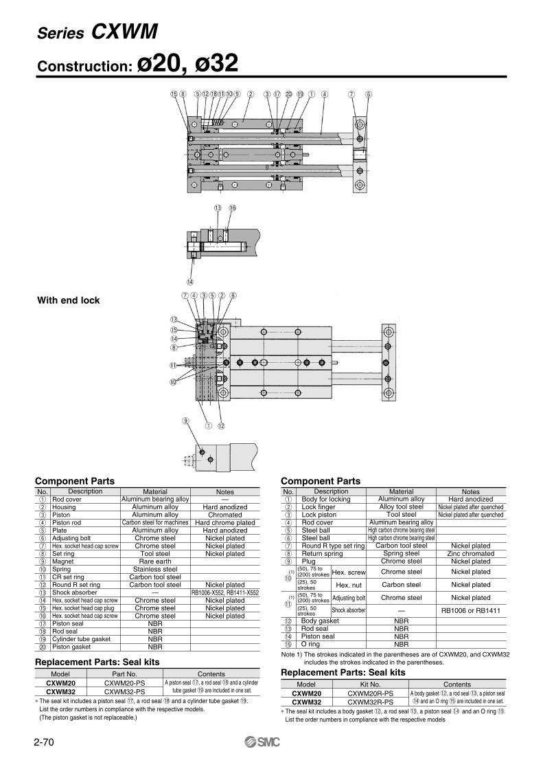
2-70
Construction: ø20, ø32
No.qwertyuio!0!1!2!3!4!5!6!7!8!9@0
Component Parts Component Parts
Rod coverHousingPistonPiston rodPlateAdjusting boltHex. socket head cap screwSet ringMagnetSpringCR set ringRound R set ringShock absorberHex. socket head cap screwHex. socket head cap plugHex. socket head cap screwPiston sealRod sealCylinder tube gasketPiston gasket
Description MaterialAluminum bearing alloy
Aluminum alloyAluminum alloy
Carbon steel for machinesAluminum alloyChrome steelChrome steel
Tool steelRare earth
Stainless steelCarbon tool steelCarbon tool steel
—Chrome steelChrome steelChrome steel
NBRNBRNBRNBR
Notes—
Hard anodizedChromated
Hard chrome platedHard anodizedNickel platedNickel platedNickel plated
Nickel platedRB1006-X552, RB1411-X552
Nickel platedNickel platedNickel plated
No.qwertyuio
Body for lockingLock fingerLock pistonRod coverSteel ballSteel ballRound R type set ringReturn springPlug
Description MaterialAluminum alloyAlloy tool steel
Tool steelAluminum bearing alloy
High carbon chrome bearing steelHigh carbon chrome bearing steel
Carbon tool steelSpring steel
Chrome steel
NotesHard anodized
Nickel plated after quenchedNickel plated after quenched
Nickel platedZinc chromated
Nickel plated
Shock absorber
Body gasketRod sealPiston sealO ring
(1)
(1)
Note 1) The strokes indicated in the parentheses are of CXWM20, and CXWM32includes the strokes indicated in the parentheses.
Replacement Parts: Seal kitsModel
∗ The seal kit includes a body gasket !2, a rod seal !3, a piston seal !4 and an O ring !5. List the order numbers in compliance with the respective models
Kit No. ContentsCXWM20R-PSCXWM32R-PS
A body gasket !2, a rod seal !3, a piston seal !4 and an O ring !5 are included in one set.
CXWM20CXWM32
Replacement Parts: Seal kitsModel
∗ The seal kit includes a piston seal !7, a rod seal !8 and a cylinder tube gasket !9. List the order numbers in compliance with the respective models.(The piston gasket is not replaceable.)
Part No. ContentsCXWM20-PSCXWM32-PS
A piston seal !7, a rod seal !8 and a cylinder tube gasket !9 are included in one set.
CXWM20CXWM32
!2!3!4!5
!0
!1
(50), 75 to (200) strokes(25), 50 strokes(50), 75 to (200) strokes(25), 50 strokes
Hex. screw
Hex. nut
Adjusting bolt
NBRNBRNBRNBR
Chrome steel
Carbon steel
Chrome steel
—
Nickel plated
Nickel plated
Nickel plated
RB1006 or RB1411
With end lock
Series CXWM
2-71
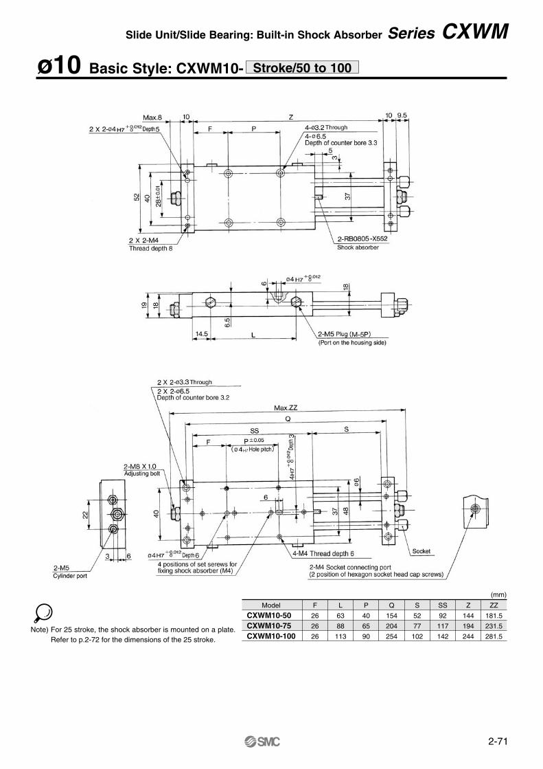
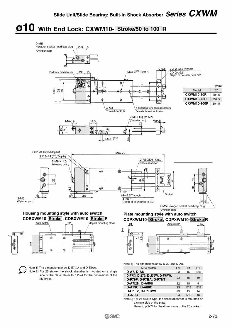
ø10 Basic Style: CXWM10- Stroke/50 to 100
Model
CXWM10-50 CXWM10-75 CXWM10-100
F
26
26
26
L
63
88
113
P
40
65
90
Q
154
204
254
S
52
77
102
SS
92
117
142
Z
144
194
244
ZZ
181.5
231.5
281.5
(mm)
Note) For 25 stroke, the shock absorber is mounted on a plate. Refer to p.2-72 for the dimensions of the 25 stroke.
Slide Unit/Slide Bearing: Built-in Shock Absorber Series CXWM
2-72
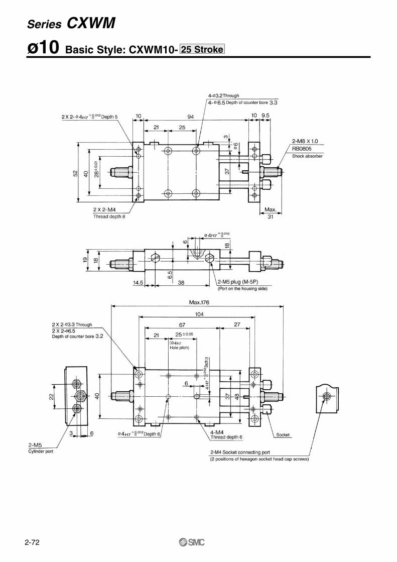
ø10 Basic Style: CXWM10- 25 Stroke
Series CXWM
2-73
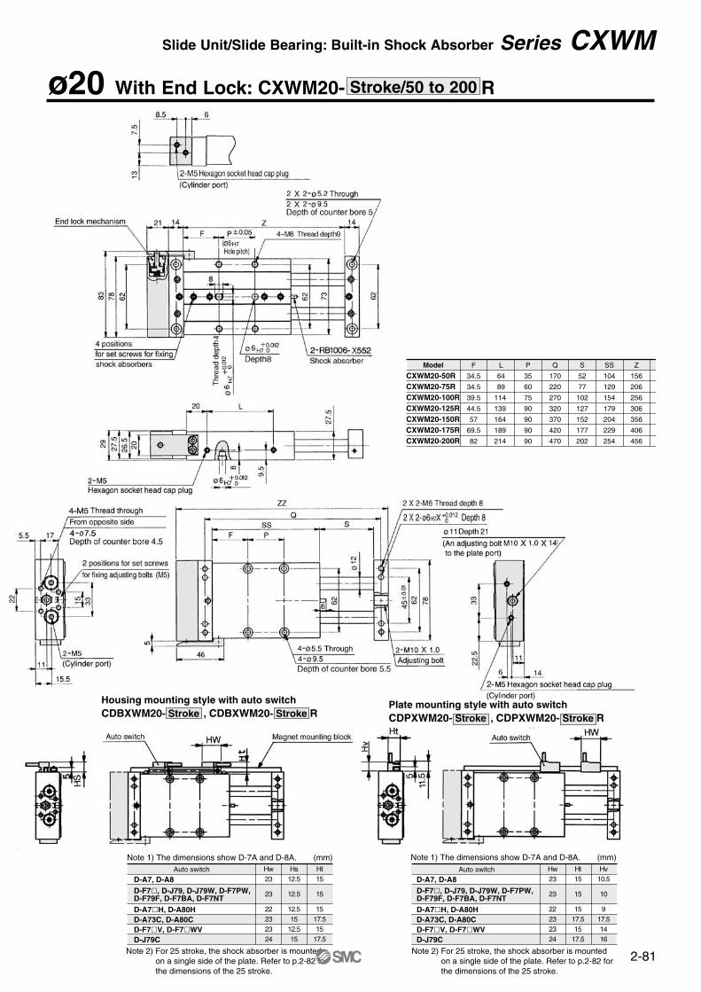
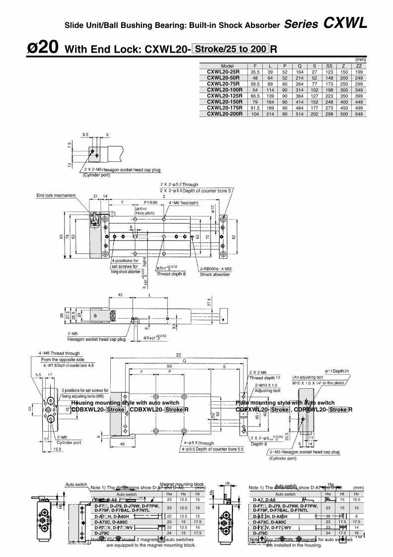
Note 1) The dimensions show D-A7 and D-A8.Auto switch Hw
23
23
22232324
Ht 15
15
1517.515
17.5
Hv10.5
10
917.51416
D-A7, D-A8D-F7, D-J79, D-J79W, D-F7PW,D-F79F, D-F7BA, D-F7NTD-A7H, D-A80HD-A73C, D-A80CD-F7V, D-F7WVD-J79C
Note 2) For 25 stroke type, the shock absorber is mounted on a single side of the plate.Refer to p.2-74 for the dimensions of the 25 stroke.
Note 1) The dimensions show D-E7A and D-E80A.Note 2) For 25 stroke, the shock absorber is mounted on a single
side of the plate. Refer to p.2-74 for the dimensions of the 25 stroke.
ZZ
204.5
254.5
304.5
(mm)
Model
CXWM10-50R CXWM10-75R CXWM10-100R
Housing mounting style with auto switchCDBXWM10- Stroke , CDBXWM10- Stroke R
Plate mounting style with auto switchCDPXWM10- Stroke , CDPXWM10- Stroke R
ø10 With End Lock: CXWM10- RStroke/50 to 100
Slide Unit/Slide Bearing: Built-in Shock Absorber Series CXWM
2-74
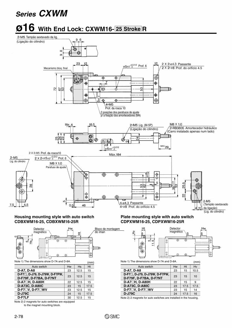
ø10 With End Lock: CXWM10- R25 Stroke
Housing mounting style with auto switchCDBXWM10-25, CDBXWM10-25R
Plate mounting style with auto switchCDPXWM10-2, CDPXWM10-25R
Note 1) The dimensions show D-A7 and D-A8. (mm)
Auto switch Hw23
23
22232324
Ht15
15
1517.515
17.5
Hv10.5
10
917.51416
D-A7, D-A8D-F7, D-J79, D-J79W, D-F7PW,D-F79F, D-F7BA, D-F7NTD-A7H, D-A80HD-A73C, D-A80CD-F7V, D-F7WVD-J79C
Note 2) 2 magnets for auto switches are installed in the housing.
Note 1) The dimensions show D-E7A and D-E80A.Note 2) 2 pieces of magnets for auto switches are equipped to the
magnet mounting block
Series CXWM
2-75
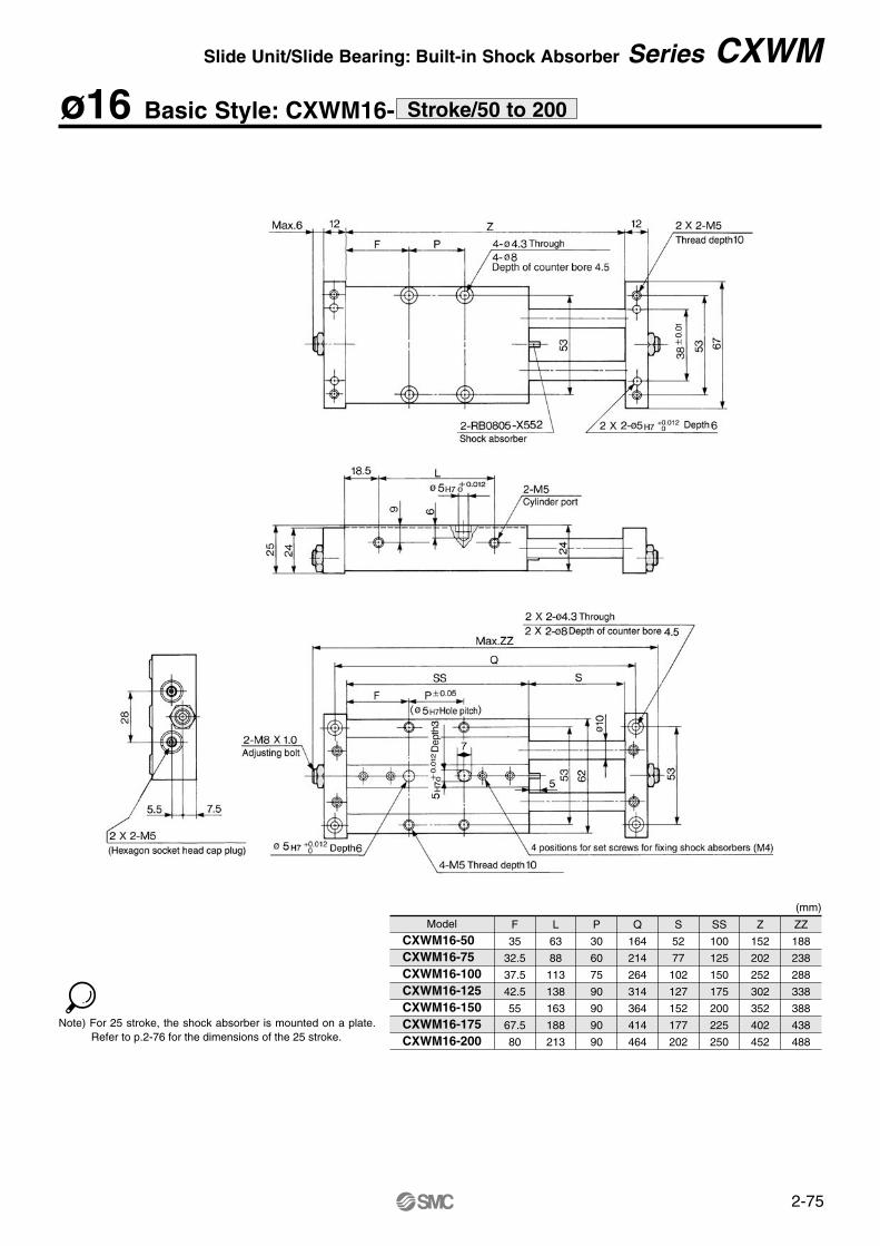
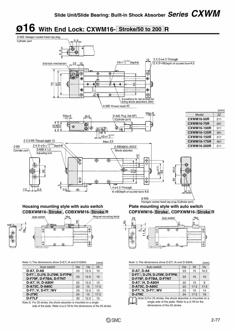
ø16 Basic Style: CXWM16- Stroke/50 to 200
Model
CXWM16-50 CXWM16-75 CXWM16-100CXWM16-125CXWM16-150CXWM16-175CXWM16-200
F
35
32.5
37.5
42.5
55
67.5
80
L
63
88
113
138
163
188
213
P
30
60
75
90
90
90
90
Q
164
214
264
314
364
414
464
S
52
77
102
127
152
177
202
SS
100
125
150
175
200
225
250
Z
152
202
252
302
352
402
452
ZZ
188
238
288
338
388
438
488
(mm)
Note) For 25 stroke, the shock absorber is mounted on a plate. Refer to p.2-76 for the dimensions of the 25 stroke.
Slide Unit/Slide Bearing: Built-in Shock Absorber Series CXWM
2-76
ø16 Basic Style: CXWM16- 25 Stroke
Series CXWM
2-77
Note 1) The dimensions show D-E7A and D-E80A.
Note 2) For 25 stroke, the shock absorber is mounted on asingle side of the plate. Refer to p.2-78 for thedimensions of the 25 stroke.
ZZ
211
261
311
361
411
461
511
(mm)
Model
CXWM16-50R CXWM16-75R CXWM16-100RCXWM16-125RCXWM16-150RCXWM16-175RCXWM16-200R
Note 1) The dimensions show D-E7A and D-E80A. (mm)Auto switch Hw
23
23
2223232430
Hs12.5
12.5
12.515
12.515
12.5
Ht15
15
1517.515
17.515
Note 2) For 25 stroke, the shock absorber is mounted on a single side of the plate. Refer to p.2-78 for the dimensions of the 25 stroke.
(mm)Auto switch Hw
23
23
22232324
Ht15
15
1517.515
17.5
Hv10.5
10
917.51416
D-A7, D-A8D-F7, D-J79, D-J79W, D-F7PW,D-F79F, D-F7BA, D-F7NTD-A7H, D-A80HD-A73C, D-A80CD-F7V, D-F7WVD-J79C
D-A7, D-A8D-F7, D-J79, D-J79W, D-F7PW,D-F79F, D-F7BA, D-F7NTD-A7H, D-A80HD-A73C, D-A80CD-F7V, D-F7WVD-J79CD-F7LF
Housing mounting style with auto switchCDBXWM16- Stroke , CDBXWM16- Stroke R
Plate mounting style with auto switchCDPXWM16- Stroke , CDPXWM16- Stroke R
ø16 With End Lock: CXWM16- RStroke/50 to 200
Slide Unit/Slide Bearing: Built-in Shock Absorber Series CXWM
PassanteProf. do orifício 4.5
Prof. 6Mecanismo bloq. final
(Ligação do cilindro)
Prof. da rosca 102 posições dos parafusos de ajustep/ a fixação dos amortecedores (M4)
(Ligação do cilindro) Amortecedor hidráulico(Carro instalado apenas num lado)
Máx
MáxProf. 6
Parafuso de ajuste
Lig. do cilindro
PassanteProf. do orifício 4.5
(Tampão sextavadoda ligação)(Lig. do cilindro)
Detectormagnético
Detectormagnético
Bloco de montagemdo íman
Tampão sextavado da lig.
Lig. (M-5P)
Prof. da rosca10
Housing mounting style with auto switchCDBXWM16-25, CDBXWM16-25R
Plate mounting style with auto switchCDPXWM16-25, CDPXWM16-25R
Note 1) The dimensions show D-7A and D-8A. (mm)
Auto switch Hw23
23
22232324
Ht15
15
1517.515
17.5
Hv10.5
10
917.51416
D-A7, D-A8D-F7, D-J79, D-J79W, D-F7PW, D-F79F, D-F7BA, D-F7NTD-A7H, D-A80HD-A73C, D-A80CD-F7V, D-F7WVD-J79C
Note 2) 2 magnets for auto switches are installed in the housing.
Note 1) The dimensions show D-7A and D-8A. (mm)Auto switch Hw
23
23
2223232430
Hs12.5
12.5
12.515
12.515
12.5
Ht15
15
1517.515
17.515
D-A7, D-A8D-F7, D-J79, D-J79W, D-F7PW,D-F79F, D-F7BA, D-F7NTD-A7H, D-A80HD-A73C, D-A80CD-F7V, D-F7WVD-J79CD-F7LF
Note 2) 2 magnets for auto switches are equippedto the magnet mounting block.
2-78
ø16 With End Lock: CXWM16- R25 Stroke
Series CXWM
2-79
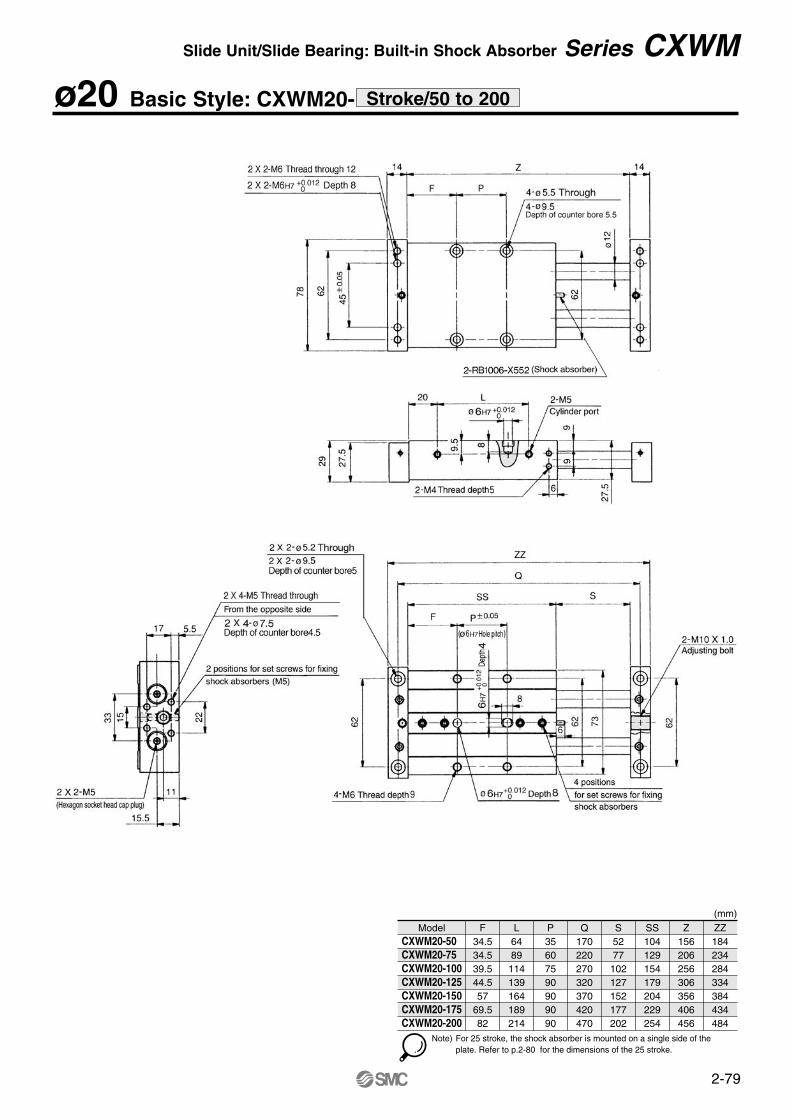
ø20 Basic Style: CXWM20- Stroke/50 to 200
ModelCXWM20-50 CXWM20-75 CXWM20-100CXWM20-125CXWM20-150CXWM20-175CXWM20-200
F34.534.539.544.557
69.582
L6489
114139164189214
P35607590909090
Q170220270320370420470
S5277102127152177202
SS104129154179204229254
Z156206256306356406456
ZZ184234284334384434484
(mm)
Note) For 25 stroke, the shock absorber is mounted on a single side of theplate. Refer to p.2-80 for the dimensions of the 25 stroke.
Slide Unit/Slide Bearing: Built-in Shock Absorber Series CXWM
Model
CXWM20-50RCXWM20-75RCXWM20-100R CXWM20-125R CXWM20-150R CXWM20-175R CXWM20-200R
F
34.5
34.5
39.5
44.5
57
69.5
82
L
64
89
114
139
164
189
214
P
35
60
75
90
90
90
90
Q
170
220
270
320
370
420
470
S
52
77
102
127
152
177
202
SS
104
129
154
179
204
229
254
Z
156
206
256
306
356
406
456
ZZ
205
255
305
355
405
455
505
(mm)
Hw23
23
22232324
Hs12.5
12.5
12.515
12.515
Ht15
15
1517.515
17.5
Note 1) The dimensions show D-7A and D-8A. (mm)
Note 2) For 25 stroke, the shock absorber is mounted on a single side of the plate. Refer to p.2-82 for the dimensions of the 25 stroke.
Hw23
23
22232324
Ht15
15
1517.515
17.5
Hv10.5
10
917.51416
Note 1) The dimensions show D-7A and D-8A. (mm)
Note 2) For 25 stroke, the shock absorber is mounted on a single side of the plate. Refer to p.2-82 for the dimensions of the 25 stroke.
Housing mounting style with auto switchCDBXWM20- Stroke , CDBXWM20- Stroke R
Plate mounting style with auto switchCDPXWM20- Stroke , CDPXWM20- Stroke R
D-A7, D-A8D-F7, D-J79, D-J79W, D-F7PW,D-F79F, D-F7BA, D-F7NTD-A7H, D-A80HD-A73C, D-A80CD-F7V, D-F7WVD-J79C
Auto switch Auto switch
D-A7, D-A8D-F7, D-J79, D-J79W, D-F7PW, D-F79F, D-F7BA, D-F7NTD-A7H, D-A80HD-A73C, D-A80CD-F7V, D-F7WVD-J79C
2-80
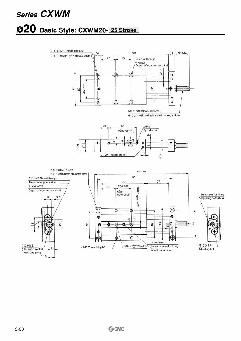
ø20 Basic Style: CXWM20- 25 Stroke
Series CXWM
Model
CXWM20-50RCXWM20-75RCXWM20-100R CXWM20-125R CXWM20-150R CXWM20-175R CXWM20-200R
F
34.5
34.5
39.5
44.5
57
69.5
82
L
64
89
114
139
164
189
214
P
35
60
75
90
90
90
90
Q
170
220
270
320
370
420
470
S
52
77
102
127
152
177
202
SS
104
129
154
179
204
229
254
Z
156
206
256
306
356
406
456
ZZ
205
255
305
355
405
455
505
(mm)
Hw23
23
22232324
Hs12.5
12.5
12.515
12.515
Ht15
15
1517.515
17.5
Note 1) The dimensions show D-7A and D-8A. (mm)
Note 2) For 25 stroke, the shock absorber is mounted on a single side of the plate. Refer to p.2-82 for the dimensions of the 25 stroke.
Hw23
23
22232324
Ht15
15
1517.515
17.5
Hv10.5
10
917.51416
Note 1) The dimensions show D-7A and D-8A. (mm)
Note 2) For 25 stroke, the shock absorber is mounted on a single side of the plate. Refer to p.2-82 for the dimensions of the 25 stroke.
Housing mounting style with auto switchCDBXWM20- Stroke , CDBXWM20- Stroke R
Plate mounting style with auto switchCDPXWM20- Stroke , CDPXWM20- Stroke R
D-A7, D-A8D-F7, D-J79, D-J79W, D-F7PW,D-F79F, D-F7BA, D-F7NTD-A7H, D-A80HD-A73C, D-A80CD-F7V, D-F7WVD-J79C
Auto switch Auto switch
D-A7, D-A8D-F7, D-J79, D-J79W, D-F7PW, D-F79F, D-F7BA, D-F7NTD-A7H, D-A80HD-A73C, D-A80CD-F7V, D-F7WVD-J79C
2-81
ø20 With End Lock: CXWM20- RStroke/50 to 200
Slide Unit/Slide Bearing: Built-in Shock Absorber Series CXWM
2-82
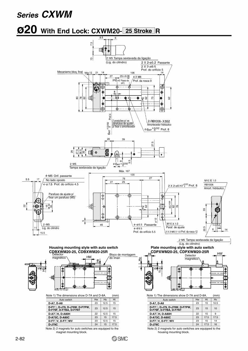
(Lig. do cilindro) Passante
Prof. do orifício 5Mecanismo bloq. final
Passo doorif.)
Prof. da rosca 9
Máx.
Amortecedor hidráulico2 posições p/ os parafusos de ajustep/ fixar o amortecedor
Prof
.4
Prof. 8
Tampa sextavada da ligaçãoMáx.
No lado opostoProf. do orifício 4.5
Parafuso de ajuste p/fixar um parafuso (M5)
Lig. do cilindro
Prof. 8Amort. hidráulico
Passante
Prof. do orifício 5.5
Paraf. de ajuste
Prof. da rosca 12
(Lig. do cilindro)
Detectormagnético
Detectormagnético
Bloco de montagemdo íman
Tampa sextavada da ligação
Orif. passante
Tampa sextavada da ligação
Hw23
23
22232324
Hs12.5
12.5
12.515
12.515
Ht15
15
1517.515
17.5
Note 1) The dimensions show D-7A and D-8A. (mm)
Note 2) 2 magnets for auto switches are equipped to the magnet mounting block.
Hw23
23
22232324
Ht15
15
1517.515
17.5
Hv10.5
10
917.51416
Note 1) The dimensions show D-7A and D-8A. (mm)
Note 2) 2 magnets for auto switches are equipped to the housing mounting block.
Housing mounting style with auto switchCDBXWM20-25, CDBXWM20-25R
Plate mounting style with auto switchCDPXWM20-25, CDPXWM20-25R
D-A7, D-A8D-F7, D-J79, D-J79W, D-F7PW,D-F79F, D-F7BA, D-F7NTD-A7H, D-A80HD-A73C, D-A80CD-F7V, D-F7WVD-J79C
Auto switch
D-A7, D-A8D-F7, D-J79, D-J79W, D-F7PW,D-F79F, D-F7BA, D-F7NTD-A7H, D-A80HD-A73C, D-A80CD-F7V, D-F7WVD-J79C
Auto switch
ø20 With End Lock: CXWM20- R25 Stroke
Series CXWM
2-83
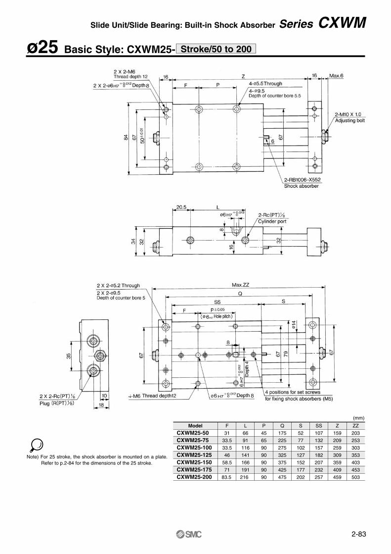
ø25 Basic Style: CXWM25- Stroke/50 to 200
Model
CXWM25-50 CXWM25-75 CXWM25-100CXWM25-125CXWM25-150CXWM25-175CXWM25-200
F
31
33.5
33.5
46
58.5
71
83.5
L
66
91
116
141
166
191
216
P
45
65
90
90
90
90
90
Q
175
225
275
325
375
425
475
S
52
77
102
127
152
177
202
SS
107
132
157
182
207
232
257
Z
159
209
259
309
359
409
459
ZZ
203
253
303
353
403
453
503
(mm)
Note) For 25 stroke, the shock absorber is mounted on a plate. Refer to p.2-84 for the dimensions of the 25 stroke.
Slide Unit/Slide Bearing: Built-in Shock Absorber Series CXWM
2-84
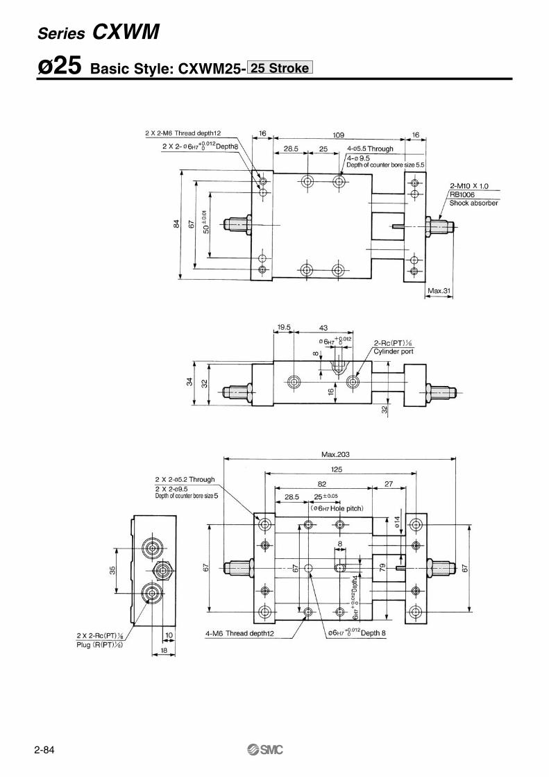
ø25 Basic Style: CXWM25- 25 Stroke
Series CXWM
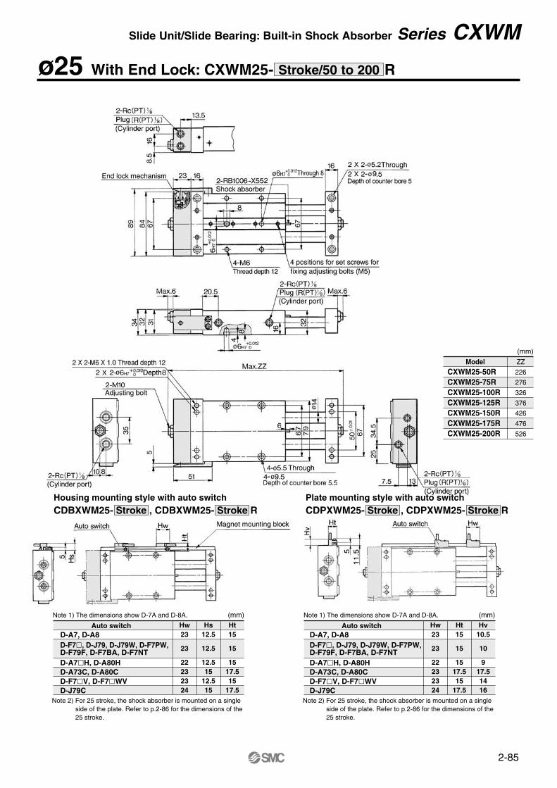
2-85
ø25 With End Lock: CXWM25- R
Hw23
23
22232324
Hs12.5
12.5
12.515
12.515
Ht15
15
1517.515
17.5
Note 1) The dimensions show D-7A and D-8A. (mm)
Note 2) For 25 stroke, the shock absorber is mounted on a single side of the plate. Refer to p.2-86 for the dimensions of the 25 stroke.
Hw23
23
22232324
Ht15
15
1517.515
17.5
Hv10.5
10
917.51416
Note 1) The dimensions show D-7A and D-8A. (mm)
Note 2) For 25 stroke, the shock absorber is mounted on a single side of the plate. Refer to p.2-86 for the dimensions of the 25 stroke.
Housing mounting style with auto switchCDBXWM25- Stroke , CDBXWM25- Stroke R
Plate mounting style with auto switchCDPXWM25- Stroke , CDPXWM25- Stroke R
ModelCXWM25-50RCXWM25-75RCXWM25-100R CXWM25-125R CXWM25-150R CXWM25-175R CXWM25-200R
ZZ
226
276
326
376
426
476
526
(mm)
D-A7, D-A8D-F7, D-J79, D-J79W, D-F7PW,D-F79F, D-F7BA, D-F7NTD-A7H, D-A80HD-A73C, D-A80CD-F7V, D-F7WVD-J79C
Auto switchD-A7, D-A8D-F7, D-J79, D-J79W, D-F7PW,D-F79F, D-F7BA, D-F7NTD-A7H, D-A80HD-A73C, D-A80CD-F7V, D-F7WVD-J79C
Auto switch
Slide Unit/Slide Bearing: Built-in Shock Absorber Series CXWM
Stroke/50 to 200
2-86
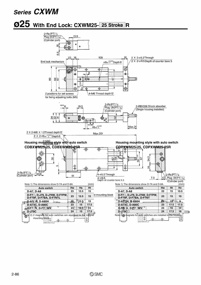
ø25 With End Lock: CXWM25- R25 Stroke
Hw23
23
22232324
Hs12.5
12.5
12.515
12.515
Ht15
15
1517.515
17.5
Note 1) The dimensions show D-7A and D-8A. (mm)
Note 2) 2 magnets for auto switches are equipped to the magnet mounting block.
Hw23
23
22232324
Ht15
15
1517.515
17.5
Hv10.5
10
917.51416
Note 1) The dimensions show D-7A and D-8A. (mm)
Note 2) 2 magnets for auto switches are installed in the housing.
Housing mounting style with auto switchCDBXWM25-25, CDBXWM25-25R
Housing mounting style with auto switchCDPXWM25-25, CDPXWM25-25R
D-A7, D-A8D-F7, D-J79, D-J79W, D-F7PW,D-F79F, D-F7BA, D-F7NTLD-A7H, D-A80HD-A73C, D-A80CD-F7V, D-F7WVD-J79C
Auto switch Auto switchD-A7, D-A8D-F7, D-J79, D-J79W, D-F7PW,D-F79F, D-F7BA, D-F7NTD-A7H, D-A80HD-A73C, D-A80CD-F7V, D-F7WVD-J79C
Series CXWM
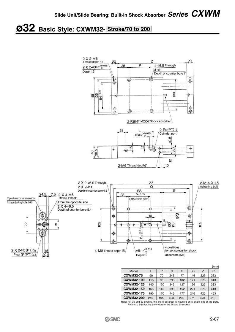
2-87
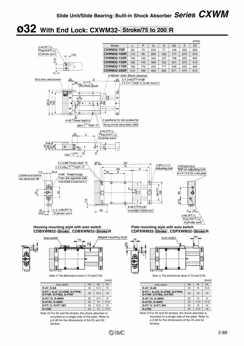
ø32 Basic Style: CXWM32- Stroke/70 to 200
Model
CXWM32-75 CXWM32-100CXWM32-125CXWM32-150CXWM32-175CXWM32-200
L
90
115
140
165
190
215
P
70
95
120
145
170
195
Q
243
293
343
393
443
493
S
77
102
127
152
177
202
SS
146
171
196
221
246
271
Z
223
273
323
373
423
473
ZZ
263
313
363
413
463
513Note) For 25 and 50 strokes, the shock absorber is mounted on a single side of the plate.
Refer to p 2-88 for the dimensions of the 25 and 50 strokes.
(mm)
Slide Unit/Slide Bearing: Built-in Shock Absorber Series CXWM
2-88
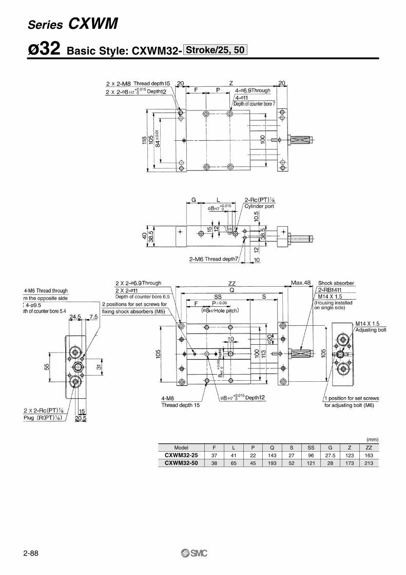
ø32 Basic Style: CXWM32- Stroke/25, 50
Model
CXWM32-25CXWM32-50
F
37
38
L
41
65
P
22
45
Q
143
193
S
27
52
SS
96
121
G
27.5
28
Z
123
173
ZZ
163
213
(mm)
Series CXWM
2-89
Hw23
23
22232324
Hs12.5
12.5
12.515
12.515
Ht15
15
1517.515
17.5
(mm) (mm)Hw23
23
22232324
Ht15
15
1517.515
17.5
Hv10.5
10
917.51416
Note 2) For 25 and 50 strokes, the shock absorber is mounted on a single side of the plate. Refer to p.2-90 for the dimensions of the 25 and 50 strokes.
Housing mounting style with auto switchCDBXWM32- Stroke , CDBXWM32- Stroke R
Plate mounting style with auto switchCDPXWM32- Stroke , CDPXWM32- Stroke R
Model
CXWM32-75RCXWM32-100R CXWM32-125R CXWM32-150R CXWM32-175R CXWM32-200R
L
90
115
140
165
190
215
P
70
95
120
145
170
195
Q
243
293
343
393
443
493
S
77
102
127
152
177
202
SS
146
171
196
221
246
271
Z
223
273
323
373
423
473
ZZ
263
313
363
413
463
513
(mm)
Note 2) For 25 and 50 strokes, the shock absorber is mounted on a single side of the plate. Refer to p.2-90 for the dimensions of the 25 and 50 strokes.
D-A7, D-A8D-F7, D-J7, D-J79W, D-F7PW,D-F79F, D-F7BA, D-F7NTD-A7H, D-A80HD-A73C, D-A80CD-F7V, D-F7WVD-J79C
Auto switch Auto switchD-A7, D-A8D-F7, D-J79, D-J79W, D-F7PW,D-F79F, D-F7BA, D-F7NTD-A7H, D-A80HD-A73C, D-A80CD-F7V, D-F7WVD-J79C
ø32 With End Lock: CXWM32- RStroke/75 to 200
Slide Unit/Slide Bearing: Built-in Shock Absorber Series CXWM
2-90
ø32 With End Lock: CXWM32- RStroke/25, 50
Hw23
23
22232324
Hs12.5
12.5
12.515
12.515
Ht15
15
1517.515
17.5
Note 1) The dimensions show D-7A and D-8A Note 1) The dimensions show D-7A and D-8A
Note 2) 2 magnets for auto switches are equipped to the magnet mounting block.
Hw23
23
22232324
Ht15
15
1517.515
17.5
Hv10.5
10
917.51416
Note 2) 2 magnets for auto switches are installed in the housing.
Housing mounting style with auto switchCDBXWM32-25, 50, CDBXWM32-25R, 50R
Plate mounting style with auto switchCDPXWM32-25, 50, CDPXWM32-25R, 50R
ModelCXWM32-25RCXWM32-50R
F3738
L4165
P2245
Q143193
S2752
SS96121
G27.528
Z123173
ZZ163213
(mm)
D-A7, D-A8D-F7, D-J79, D-J79W, D-F7PW,D-F79F, D-F7BA, D-F7NTD-A7H, D-A80HD-A73C, D-A80CD-F7V, D-F7WVD-J79C
Auto switch Auto switchD-A7, D-A8D-F7, D-J79, D-J79W, D-F7PW,D-F79F, D-F7BA, D-F7NTD-A7H, D-A80HD-A73C, D-A80CD-F7V, D-F7WVD-J79C
(mm) (mm)
Series CXWM
2-91
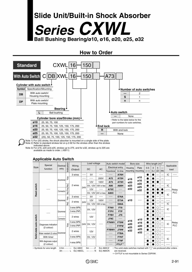
CXWL
C XWLWith Auto Switch
Standard 16
A7316
150
150DB
Cylinder with auto switchSymbol
DB
DP
Specification/Mounting
With auto switch/Housing mounting
With auto switch/Plate mounting
BearingL Ball bushing
Cylinder bore size/Stroke (mm)ø10ø16ø20ø25ø32
25, 50, 75, 100
25, 50, 75, 100, 125, 150, 175, 200
25, 50, 75, 100, 125, 150, 175, 200
25, 50, 75, 100, 125, 150, 175, 200
(25), 50, 75, 100, 125, 150, 175, 200
Note 1) For (25) stroke, the shock absorber is mounted on a single side of the plate.Note 2) Refer to standard strokes list on p.2-92 for the strokes other than the strokes
indicated above.Note 3) For ø16, ø20 and ø25, strokes up to 275, and for ø32, strokes up to 225 are
available as made to order. (-XB11)
Number of auto switches—Sn
2
1
n
Auto switch— None
∗ Refer to the table below for thepart numbers for auto switches.
End lockR—
With end lock
None
Applicable Auto Switch
Style
Ree
d s
wit
chS
olid
sta
te a
uto
sw
itch
Special
function
Diagnoses indication(2 colour)
Water resistant (2 colour)
With timer
With diagnoses output(2 colour)
Electricalentry
Grommet
Connector
Grommet
Grommet
Connector
Grommet
Indi
catio
nY
esYe
sN
oN
oN
oY
esY
es
Wiring
(Output)
3 wires
2 wires
2 wires
2 wires
3 wires
3 wires (NPN)
3 wires (PNP)
2 wires
3 wires (NPN)
3 wires (NPN)
4 wires (NPN)
3 wires (PNP)
Load voltage
DC AC
24V
24V
24V
5V
12V
5V, 12V
12V
5V, 12V
5V
12V
5V, 12V
5V, 12V
12V
5V, 12V
12V
5V, 12V
200V
100V
100V or less
24V or less
100V
100V or less
Auto switch model
Electrical entry
Perpendicular
A72
A73
A80
A73C
A80C
F7NV
F7PV
F7BV
J79C
F7NWV
F7BWV
In-line
A76H
A72H
A73H
A80H
E76A
E73A
E80A
F79
F7P
J79
F79W
F7PW
J79W
F7BA
F7NT
F79F
F7LF∗∗
Bore size
Housingmounting
ø16ø20ø25ø32
Platemounting
ø10ø16ø20ø25ø32
∗ Symbols for wire length 0.5m ······· —3m ·········· L
Ex) A80CEx) A80CL
5m ········Z — ········ N
Ex) A80CZEx) A80CN
Wire length (m)∗
0.5(—)
3(L)
5(Z)
— —
— —
— —
—
—
—
—
—
—
—
—
—
—
—
—
—
—
—
—
—
—
—
—(N)
Applicable
load
IC
IC
IC
IC
IC
IC
IC
RelayPLC
RelayPLC
ø10
ø16ø20ø25ø32
ø10ø16ø20ø25ø32
∗ The solid state switches marked with “ ” are produced after orders are received.∗∗ D-F7LF is not mountable to Series CDPXW.
Slide Unit/Built-in Shock Absorber
Series CXWLBall Bushing Bearing/ø10, ø16, ø20, ø25, ø32
How to Order
2-92
Note 1) Place the center of gravity of the load and center of the slide unit close during operation. If they are placed far apart each other, consult SMC.
Note 2) The factors are obtained under the conditions of a 25 strokes plate is pushed out.
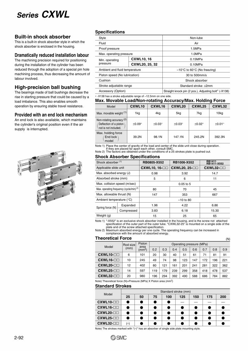
SpecificationsStyle
Fluid
Proof pressure
Max. operating pressure
Ambient and fluid temperature
Piston speed (No lubrication)
Cushion
Stroke adjustable range
Accessory (Option)
CXWL10, 16
CXWL20, 25, 32
Non-lube
Air
1.5MPa
1.0MPa
0.15MPa
0.10MPa
–10°C to 60°C (No freezing)
30 to 500mm/s
Shock absorber
Standard stroke: ±2mm
Straight knock pin (2 pcs.), Adjusting bolt∗ (-X138)
∗ -X138 has a stroke adjustable range of –12.5mm on one side.
Max. Movable Load/Non-rotating Accuracy/Max. Holding ForceModel
Max. movable weight (1)
Non-rotating accuracy (2) Deflection of a pistonrod is not included.
End lockmodel
Max. holding force
CXWL10
1kg
±0.09°
39.2N
CXWL16
4kg
±0.03°
98.1N
CXWL20
5kg
±0.03°
147.1N
CXWL25
7kg
±0.02°
245.2N
CXWL32
10kg
±0.01°
392.3N
Note 1) "-X552" is an exclusive shock absorber installed in the housing, and is the screw not attached specification of the outer part of the outer tube. “CXWL32-25” is mounted on a single side of the plate and of the screw attached specification.
Note 2) Maximum absorbed energy per one cycle. The operating frequency can be increased in compliance with the amount of absorbed energy.
Shock Absorber SpecificationsShock absorber (1)
Applicable slide unit
Max. absorbed energy (J)
Absorbed stroke (mm)
Max. collision speed (m/sec)
Max. operating frequency (cycle/min) (2)
Max. allowable thrust (N)
Ambient temperature (°C)
Spring force (N)
Weight (g)
CXWL10, 16-0.98
5
80
147
1.96
3.83
15
CXWL20, 25-3.92
6
0.05 to 5
70
353
–10 to 80
4.22
6.18
25
CXWL32-14.7
11
45
667
6.86
15.30
65
Note) The strokes marked with "(∗)" has an absorber of single side plate mounting style.
Theoretical Force (N)
Model
CXWL10-CXWL16-CXWL20-CXWL25-CXWL32-
Rod size(mm)
Pistonarea
(mm2)
6
10
12
14
20
101
245
402
597
980
Operating pressure (MPa)
0.2
20
49
80
119
196
0.3
30
74
121
179
294
0.4
40
98
161
239
392
0.5
51
123
201
299
490
0.6
61
147
241
358
588
0.7
71
172
281
418
686
0.8
81
196
322
478
784
0.9
91
221
362
537
882
Note) Theoretical force (N)=Pressure (MPa) X Piston area (mm2)
Standard Strokes
Model
CXWL10-CXWL16-CXWL20-CXWL25-CXWL32-
Standard stroke (mm)
25
(∗)
50 75 100 125
—
150
—
175
—
200
—
Expanded
Compressed
RB0805-X552 RB1006-X552 RB1411RB1411-X552
Built-in shock absorberThis is a built-in shock absorber style in which theshock absorber is enclosed in the housing.
Dramatically reduced installation labourThe machining precision required for positioning during the installation of the cylinder has been reduced through the adoption of a special pin hole machining process, thus decreasing the amount of labour involved.
High-precision ball bushingThe bearings made of ball bushings decrease the rise in starting pressure that could be caused by a load imbalance. This also enables smooth operation by ensuring stable travel resistance.
Provided with an end lock mechanismAn end lock is also available, which maintains the cylinder's original position even if the air supply is interrupted.
Min. operating pressure
Series CXWL
2-93
ModelStroke (mm)
25
0.33
0.72
1.0
1.32
2.56
50
0.40
0.85
1.18
1.54
2.96
75
0.46
0.98
1.35
1.76
3.37
100
0.53
1.11
1.53
1.97
3.75
125
—
1.23
1.71
2.19
4.19
150
—
1.36
1.89
2.43
4.56
175
—
1.49
2.06
2.63
4.98
200
—
1.62
2.24
2.86
5.39
CXWL10
CXWL16
CXWL20
CXWL25
CXWL32
Applicable model
CXWL10
CXWL16
CXWL20
CXWL25
CXWL32
Additional weight
0.08
0.14
0.15
0.20
0.43
Pressurized port
Operating direction
A
Right
B
Left
C
Left
D
Right
E
Left
F
Right
Pressurized port
Operating direction
A
Right
B
Left
C
Left
D
Right
E
Right
F
Left
G
Left
H
Right
Model
CXWL10CXWL16CXWL20CXWL25CXWL32
Model
CXWL10CXWL16CXWL20CXWL25CXWL32
100
0.07
0.05
0.04
0.03
0.02
9.81
39.2
49
68.6
98.1
200
—
0.20
0.15
0.10
0.07
Stroke Stroke
Load (N) Load (N)
Model
CXWL10CXWL16CXWL20CXWL25CXWL32
Model∗
MS4-10
MS5-10
MS6-15
MS6-15
MS8-20
L
10
10
15
15
20
øD
4
5
6
6
8
(mm)
∗ Manufactured by Sansumi Trading Ltd.
∗ There are 16 possible reciprocating piping methods.∗ There are 9 possible reciprocating piping methods.
2.94
4.90
7.84
9.81
29.42
50
0.06
0.03
0.03
0.03
0.02
100
0.30
0.10
0.09
0.09
0.05
150
—
0.25
0.18
0.16
0.10
200
—
0.45
0.35
0.25
0.15
(mm) (mm)
Note)The factors show the total width of the deflections in the vertical direction.
(kg)
(kg)
Weight
Additional Weight for End Lock Model (CXWL-R)
Operating direction per pressurized portOperating direction of housing when the plate is fixed
With end lock (CXWL-R)Operating direction of housing when the plate is fixed
Deflection of a piston rod by centre loading (Reference)When centre loading is added to the center of the housing
When centre loading is added to the center of the plate
Accessory (Option)Straight knock pin
Slide Unit/Ball Bushing Bearing: Built-in Shock Absorber Series CXWL
2-94
Construction: ø10, ø16, ø25CXWL10
With end lock
CXWL16
With end lock
CXWL25
With end lock
Anodized
Anodized
Anodized
Hard anodized
Chromated
Quenched, Hard chrome plated
Hard anodized
Nickel plated
Nickel plated
Nickel plated
Nickel plated
Nickel plated
ø5
Nickel plated
Nickel plated
(RB0805-X552 or RB1006-X552)
Electroless nickel plated
Rod cover
Rod cover A
Rod cover B
Housing
Piston
Piston rod
Plate
Lock nut
Adjusting bolt
Set screw (For fixing rods)
Set ring (For fixing shock absorbers)
Set ring
Plug
Magnet
Set screw for seal
Spring
CR set ring
Round R set ring
Shock absorber
Socket
Gasket
Ball bushing
Rod seal
Piston seal
Piston gasket
Cylinder tube gasket
Aluminum alloy
Aluminum alloy
Aluminum alloy
Aluminum alloy
Aluminum alloy
Aluminum alloy
Carbon steel
Chrome steel
Chrome steel
Stainless steel
Carbon tool steel
Brass
Rare earth magnet
Chrome steel
Stainless steel
Carbon tool steel
Carbon tool steel
—
Brass
NBR
—
NBR
NBR
NBR
NBR
Description Material Notes No.
@7
@8
@9
#0
#1
#2
#3
#4
#5
#6
#7
#8
#9
$0
$1
Description
Body for locking
Lock finer
Lock piston
Rod cover
Return spring
Adjusting bolt
Body gasket
Rod seal
Piston seal
Steel ball
Steel ball
O ring
Round R set ring
Lock nut
Plug
Material
Aluminum alloy
Alloy tool steel
Carbon tool steel
Aluminum alloy
Spring steel
Chrome steel
NBR
NBR
NBR
High carbon chrome bearing steel
High carbon chrome bearing steel
NBR
Carbon tool steel
Carbon steel
Chrome steel
Notes
Hard anodized
Nickel plated after quenched
Zinc chromated
Nickel plated
Nickel plated
Nickel plated
Nickel plated
Component Parts Component Parts/With end lock
Replacement Parts: Seal kitsModel
∗ The seal kit includes a rod seal @3, a piston seal @4 and a cylinder tube gasket @6. List the order numbers in compliance with the respetive models.(The piston gasket @5 is not replaceable.)
Kit No. Contents
CXWL10-PS
CXWL16-PS
CXWL25-PS
A rod seal @3, a piston seal@4 and a cylinder tube gasket @6 are included in one set.
CXWL10
CXWL16
CXWL25
No.
q
w
e
r
t
y
u
i
o
!0
!1
!2
!3
!4
!5
!6
!7
!8
!9
@0
@1
@2
@3
@4
@5
@6
High carbonate chrome bearing steel pipe
Electroless nickel plated after quenched
Series CXWL
2-95
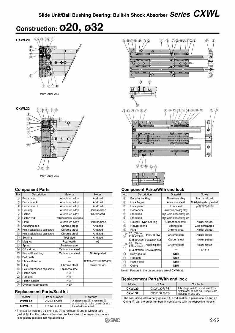
Construction: ø20, ø32
Component PartsNo.q
w
e
r
t
y
u
i
o
!2
!3
!4
!5
MaterialAluminum alloyAlloy tool steel
Tool steelAluminum bearing alloy
High carbon chrome bearing steelHigh carbon chrome bearing steel
Carbon tool steelSpring steel
Chrome steel
NotesHard andized
Nickel plating after quenched
Nickel platedZinc chromated
Nickel plated
DescriptionBody for lockingLock fingerLock pistonRod coverSteel ballSteel ballRound R type set ringReturn springPlug
Body gasketRod sealPiston sealO ring
Component Parts/With end lock
Note1) Factors in the parentheses are of CXWM32.
Replacement Parts/Seal kitModel
∗ The seal kit includes a piston seal @1, a rod seal @2 and a cylinder tubegasket @4. List the order numbers in compliance with the respective models.(The piston gasket is not replaceable.)
Order number Contents
CXWL20-PS
CXWL32-PS
A piston seal @1, a rod seal @2 and a cylinder tube gasket @4 are included in one set.
CXWL20
CXWL32
Replacement Parts/With end lockModel
∗ The seal kit includes a body gasket !2, a rod seal !3, a piston seal !4 and anO ring !5. List the order numbers in compliance with the respective models.
Kit No. Contents
CXWL20R-PS
CXWL32R-PS
A body gasket !2, a rod seal !3, a piston seal !4 and an O ring !5 are included in one set.
CXWL20
CXWL32
MaterialAluminum alloyAluminum alloyAluminum alloyAluminum alloyAluminum alloy
Hard carbon chrome bearing steelAluminum alloyChrome steelChrome steelChrome steel
Tool steelRear earth
Stainless steelCarbon tool steelCarbon tool steel
——
Chrome steelStainless steel
NBRNBRNBRNBR
No.q
w
e
r
t
y
u
i
o
!0
!1
!2
!3
!4
!5
!6
!7
!8
!9
@1
@2
@3
@4
DescriptionRod coverRod cover ARod cover BHousingPistonPiston rodPlateAdjusting boltHex. socket head cap screwHex. socket head cap screwSet ringMagnetSpringCR set ringRound R set ringBall bushShock absorberPlugHex. socket head cap screwPiston sealRod sealPiston gasketCylinder tube gasket
NotesAndizedAndizedAndized
Hard andizedChromated
—Hard andized
AndizedAndizedAndizedAndized
ø5
Nickel plated
RB1006-X552 or RB1411-X552Nickel plated
Hex. screw25, (50) to 200 strokes(25) strokes
(25) strokes
25, (50) to200 strokes
Hexagon nut
Adjusting bolt
Shock absorberNBRNBRNBRNBR
Chrome steel
Carbon steel
Chrome steel
—
Nickel plated
Nickel plated
Nickel plated
RB1411
Electroless nickel plated after quenched
!0
!1
(1)
(1)
CXWL20
With end lock
CXWL32
With end lock
Slide Unit/Ball Bushing Bearing: Built-in Shock Absorber Series CXWL
2-96
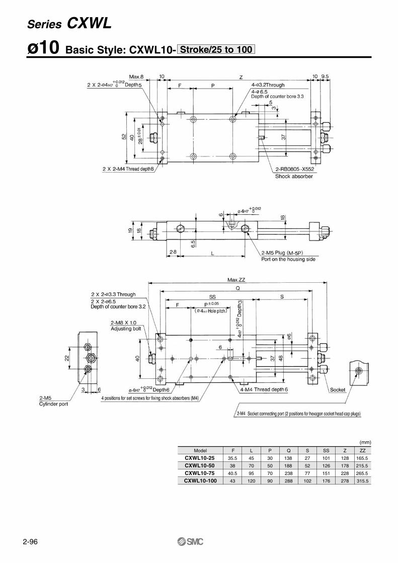
ø10 Basic Style: CXWL10- Stroke/25 to 100
Model
CXWL10-25 CXWL10-50 CXWL10-75 CXWL10-100
F
35.5
38
40.5
43
L
45
70
95
120
P
30
50
70
90
Q
138
188
238
288
S
27
52
77
102
SS
101
126
151
176
Z
128
178
228
278
ZZ
165.5
215.5
265.5
315.5
(mm)
Series CXWL
2-97
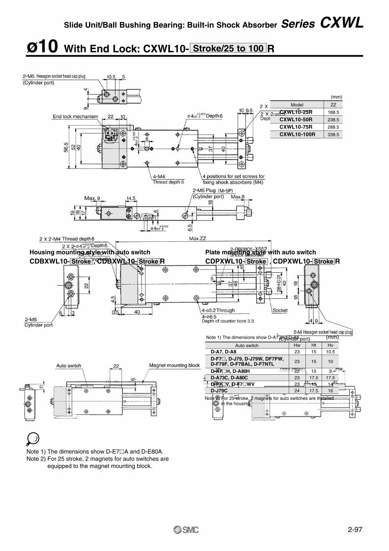
ø10 With End Lock: CXWL10- RStroke/25 to 100
Model
CXWL10-25RCXWL10-50RCXWL10-75RCXWL10-100R
ZZ
188.5
238.5
288.5
338.5
(mm)
Housing mounting style with auto switch
CDBXWL10- Stroke , CDBXWL10- Stroke RPlate mounting style with auto switch
CDPXWL10- Stroke , CDPXWL10- Stroke R
Note 1) The dimensions show D-A7 and D-A8. (mm)Hw23
23
22232324
Ht15
15
1517.515
17.5
Hv10.5
10
917.51416
Note 2) For 25 stroke, 2 magnets for auto switches are installedin the housing.
D-A7, D-A8D-F7, D-J79, D-J79W, DF7PW,D-F79F, D-F7BAL, D-F7NTLD-A7H, D-A80HD-A73C, D-A80CD-F7V, D-F7WVD-J79C
Auto switch
Note 1) The dimensions show D-E7A and D-E80A.Note 2) For 25 stroke, 2 magnets for auto switches are
equipped to the magnet mounting block.
Slide Unit/Ball Bushing Bearing: Built-in Shock Absorber Series CXWL
2-98
ø16 Basic Style: CXWL16- Stroke/25 to 200
Model
CXWL16-25 CXWL16-50 CXWL16-75 CXWL16-100CXWL16-125CXWL16-150CXWL16-175CXWL16-200
F
34.5
47
53
53
65.5
78
90.5
103
L
39
64
89
114
139
164
189
214
P
52
52
65
90
90
90
90
90
Q
160
210
260
310
360
410
460
510
S
27
52
77
102
127
152
177
202
SS
121
146
171
196
221
246
271
296
Z
148
198
248
298
348
398
448
498
ZZ
184
234
284
334
384
434
484
534
(mm)
Series CXWL
2-99
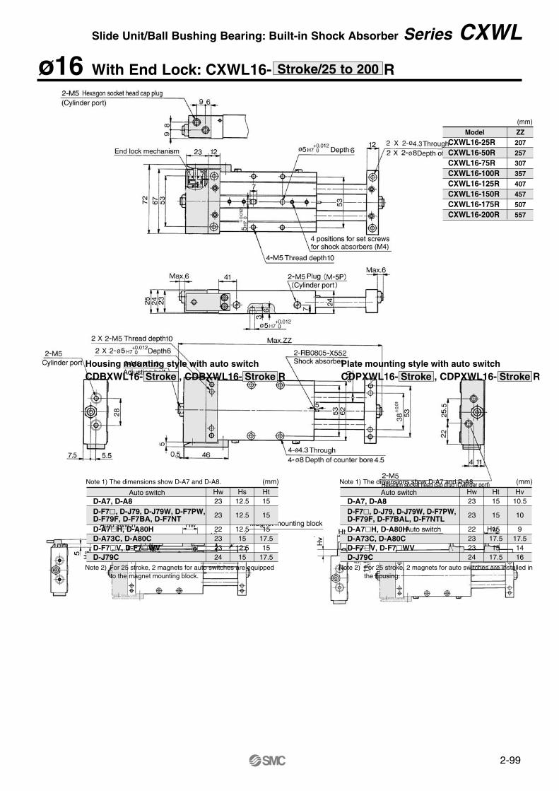
ø16 With End Lock: CXWL16- RStroke/25 to 200
Hw23
23
22232324
Hs12.5
12.5
12.515
12.515
Ht15
15
1517.515
17.5
Note 1) The dimensions show D-A7 and D-A8. (mm)
Note 2) For 25 stroke, 2 magnets for auto switches are equipped to the magnet mounting block.
Hw23
23
22232324
Ht15
15
1517.515
17.5
Hv10.5
10
917.51416
Note 1) The dimensions show D-A7 and D-A8. (mm)
Note 2) For 25 stroke, 2 magnets for auto switches are installed in the housing.
Housing mounting style with auto switchCDBXWL16- Stroke , CDBXWL16- Stroke R
Plate mounting style with auto switchCDPXWL16- Stroke , CDPXWL16- Stroke R
(mm)
ModelCXWL16-25RCXWL16-50RCXWL16-75RCXWL16-100RCXWL16-125RCXWL16-150RCXWL16-175RCXWL16-200R
ZZ207257307357407457507557
D-A7, D-A8D-F7, D-J79, D-J79W, D-F7PW,D-F79F, D-F7BA, D-F7NTD-A7H, D-A80HD-A73C, D-A80CD-F7V, D-F7WVD-J79C
Auto switch Auto switchD-A7, D-A8D-F7, D-J79, D-J79W, D-F7PW,D-F79F, D-F7BAL, D-F7NTLD-A7H, D-A80HD-A73C, D-A80CD-F7V, D-F7WVD-J79C
Slide Unit/Ball Bushing Bearing: Built-in Shock Absorber Series CXWL
2-100
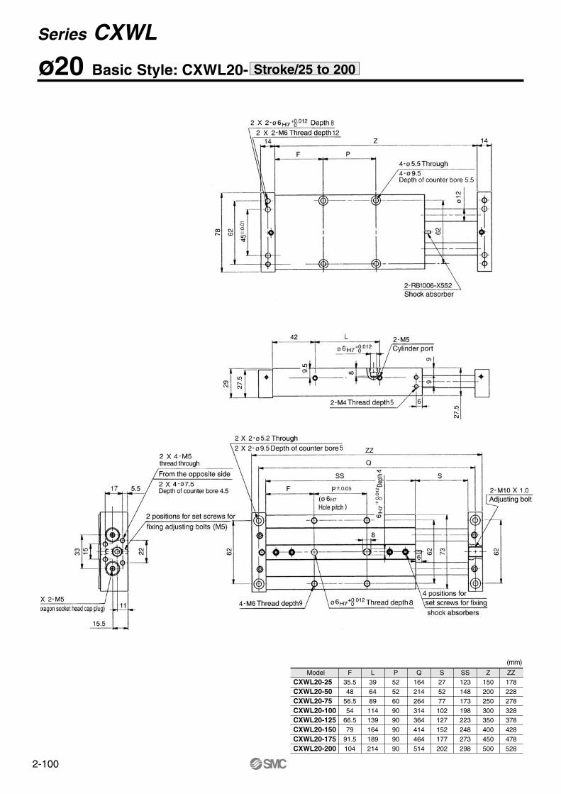
ø20 Basic Style: CXWL20- Stroke/25 to 200
ModelCXWL20-25 CXWL20-50 CXWL20-75 CXWL20-100CXWL20-125CXWL20-150CXWL20-175CXWL20-200
F35.548
56.554
66.579
91.5104
L396489
114139164189214
P5252609090909090
Q164214264314364414464514
S275277
102127152177202
SS123148173198223248273298
Z150200250300350400450500
ZZ178228278328378428478528
(mm)
Series CXWL
2-101
ø20 With End Lock: CXWL20- RStroke/25 to 200
Slide Unit/Ball Bushing Bearing: Built-in Shock Absorber Series CXWL
Hw23
23
22232324
Hs12.5
12.5
12.515
12.515
Ht15
15
1517.515
17.5
Note 1) The dimensions show D-A7 and D-A8. (mm)
Note 2) For 25 stroke, 2 magnets for auto switches are equipped to the magnet mounting block.
Hw23
23
22232324
Ht15
15
1517.515
17.5
Hv10.5
10
917.51416
Note 1) The dimensions show D-A7 and D-A8. (mm)
Note 2) For 25 stroke, 2 magnets for auto switches are installed in the housing.
Housing mounting style with auto switchCDBXWL20- Stroke , CDBXWL20- Stroke R
Plate mounting style with auto switchCDPXWL20- Stroke , CDPXWL20- Stroke R
ModelCXWL20-25RCXWL20-50RCXWL20-75RCXWL20-100R CXWL20-125R CXWL20-150R CXWL20-175R CXWL20-200R
F35.548
56.554
66.579
91.5104
L396489
114139164189214
P5252609090909090
Q164214264314364414464514
S275277
102127152177202
SS123148173198223248273298
Z 150200250300350400450500
ZZ199249299349399449499549
(mm)
D-A7, D-A8D-F7, D-J79, D-J79W, D-F7PW,D-F79F, D-F7BAL, D-F7NTLD-A7H, D-A80HD-A73C, D-A80CD-F7V, D-F7WVD-J79C
Auto switch Auto switch
D-A7, D-A8D-F7, D-J79, D-J79W, D-F7PW, D-F79F, D-F7BAL, D-F7NTLD-A7H, D-A80HD-A73C, D-A80CD-F7V, D-F7WVD-J79C
2-102
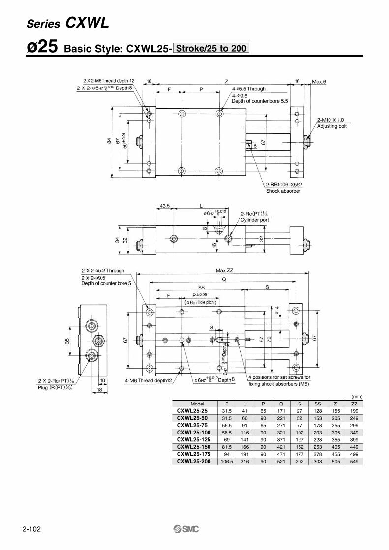
ø25 Basic Style: CXWL25- Stroke/25 to 200
Model
CXWL25-25 CXWL25-50 CXWL25-75 CXWL25-100CXWL25-125CXWL25-150CXWL25-175CXWL25-200
F
31.5
31.5
56.5
56.5
69
81.5
94
106.5
L
41
66
91
116
141
166
191
216
P
65
90
65
90
90
90
90
90
Q
171
221
271
321
371
421
471
521
S
27
52
77
102
127
152
177
202
SS
128
153
178
203
228
253
278
303
Z
155
205
255
305
355
405
455
505
ZZ
199
249
299
349
399
449
499
549
(mm)
Series CXWL
2-103
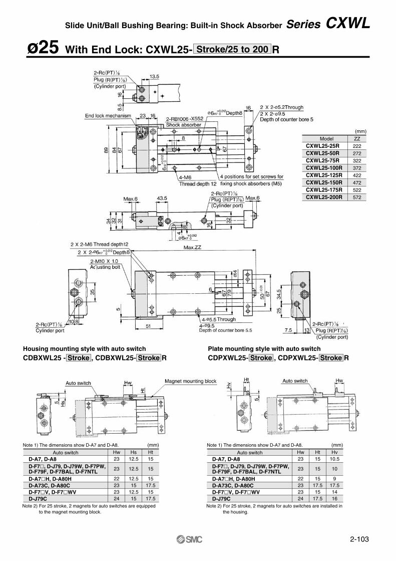
ø25 With End Lock: CXWL25- RStroke/25 to 200
Hw23
23
22232324
Hs12.5
12.5
12.515
12.515
Ht15
15
1517.515
17.5
Note 1) The dimensions show D-A7 and D-A8. (mm)
Note 2) For 25 stroke, 2 magnets for auto switches are equipped to the magnet mounting block.
Hw23
23
22232324
Ht15
15
1517.515
17.5
Hv10.5
10
917.51416
Note 1) The dimensions show D-A7 and D-A8. (mm)
Note 2) For 25 stroke, 2 magnets for auto switches are installed in the housing.
Housing mounting style with auto switchCDBXWL25 - Stroke , CDBXWL25- Stroke R
Plate mounting style with auto switchCDPXWL25- Stroke , CDPXWL25- Stroke R
Model
CXWL25-25RCXWL25-50RCXWL25-75RCXWL25-100R CXWL25-125R CXWL25-150R CXWL25-175R CXWL25-200R
ZZ
222
272
322
372
422
472
522
572
(mm)
D-A7, D-A8D-F7, D-J79, D-J79W, D-F7PW,D-F79F, D-F7BAL, D-F7NTLD-A7H, D-A80HD-A73C, D-A80CD-F7V, D-F7WVD-J79C
Auto switch Auto switchD-A7, D-A8D-F7, D-J79, D-J79W, D-F7PW,D-F79F, D-F7BAL, D-F7NTLD-A7H, D-A80HD-A73C, D-A80CD-F7V, D-F7WVD-J79C
Slide Unit/Ball Bushing Bearing: Built-in Shock Absorber Series CXWL
2-104
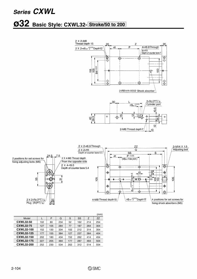
ø32 Basic Style: CXWL32- Stroke/50 to 200
Model
CXWL32-50 CXWL32-75 CXWL32-100CXWL32-125CXWL32-150CXWL32-175CXWL32-200
L
102
127
152
177
202
227
252
P
80
105
130
155
180
205
230
Q
234
284
334
384
434
484
534
S
52
77
102
127
152
177
202
SS
162
187
212
237
262
287
312
Z
214
264
314
364
414
464
514
ZZ
254
304
354
404
454
504
554
(mm)
Series CXWL
2-105
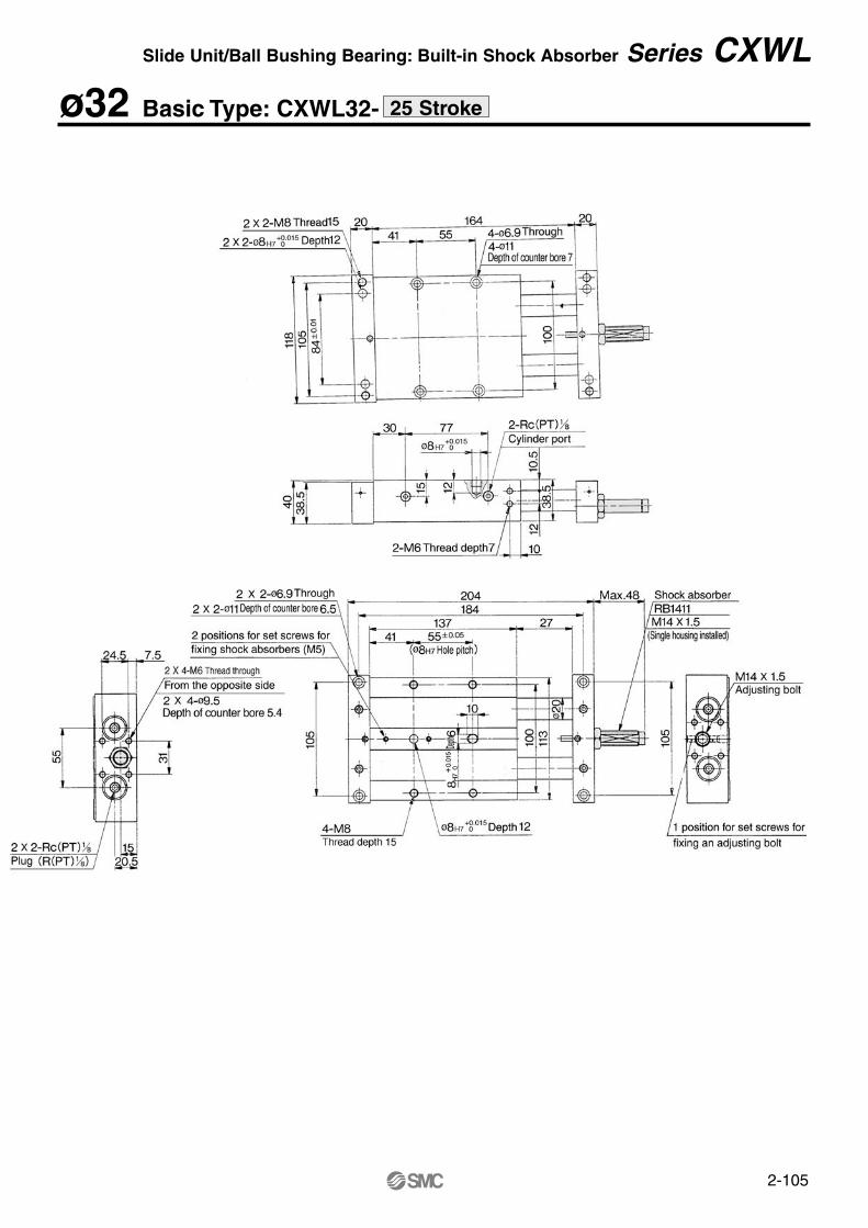
ø32 Basic Type: CXWL32- 25 Stroke
Slide Unit/Ball Bushing Bearing: Built-in Shock Absorber Series CXWL
2-106
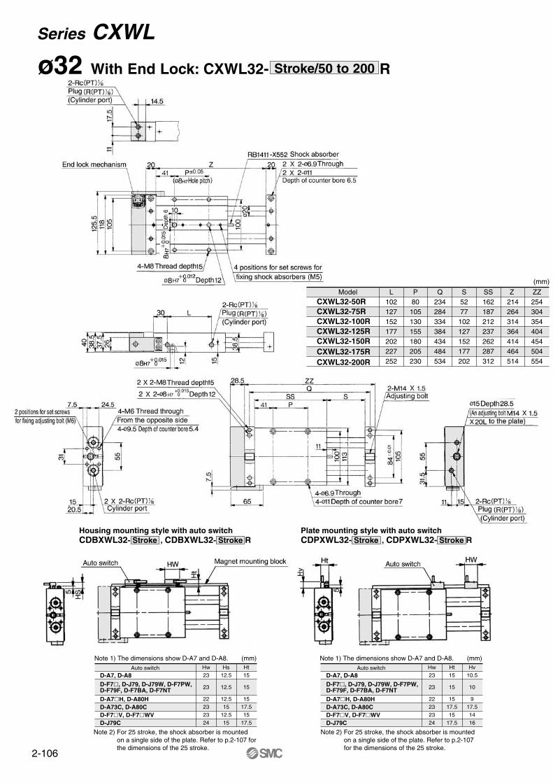
ø32 With End Lock: CXWL32- RStroke/50 to 200
Hw23
23
22232324
Hs12.5
12.5
12.515
12.515
Ht15
15
1517.515
17.5
Note 1) The dimensions show D-A7 and D-A8. (mm) Note 1) The dimensions show D-A7 and D-A8. (mm)
Note 2) For 25 stroke, the shock absorber is mounted on a single side of the plate. Refer to p.2-107 for the dimensions of the 25 stroke.
Hw23
23
22232324
Ht15
15
1517.515
17.5
Hv10.5
10
917.51416
Note 2) For 25 stroke, the shock absorber is mounted on a single side of the plate. Refer to p.2-107 for the dimensions of the 25 stroke.
Housing mounting style with auto switchCDBXWL32- Stroke , CDBXWL32- Stroke R
Plate mounting style with auto switchCDPXWL32- Stroke , CDPXWL32- Stroke R
(mm)
ModelCXWL32-50RCXWL32-75RCXWL32-100R CXWL32-125R CXWL32-150R CXWL32-175R CXWL32-200R
L102127152177202227252
P80105130155180205230
Q234284334384434484534
S5277102127152177202
SS162187212237262287312
Z 214264314364414464514
ZZ254304354404454504554
D-A7, D-A8D-F7, D-J79, D-J79W, D-F7PW, D-F79F, D-F7BA, D-F7NTD-A7H, D-A80HD-A73C, D-A80CD-F7V, D-F7WVD-J79C
Auto switch Auto switchD-A7, D-A8D-F7, D-J79, D-J79W, D-F7PW, D-F79F, D-F7BA, D-F7NTD-A7H, D-A80HD-A73C, D-A80CD-F7V, D-F7WVD-J79C
Series CXWL
2-107
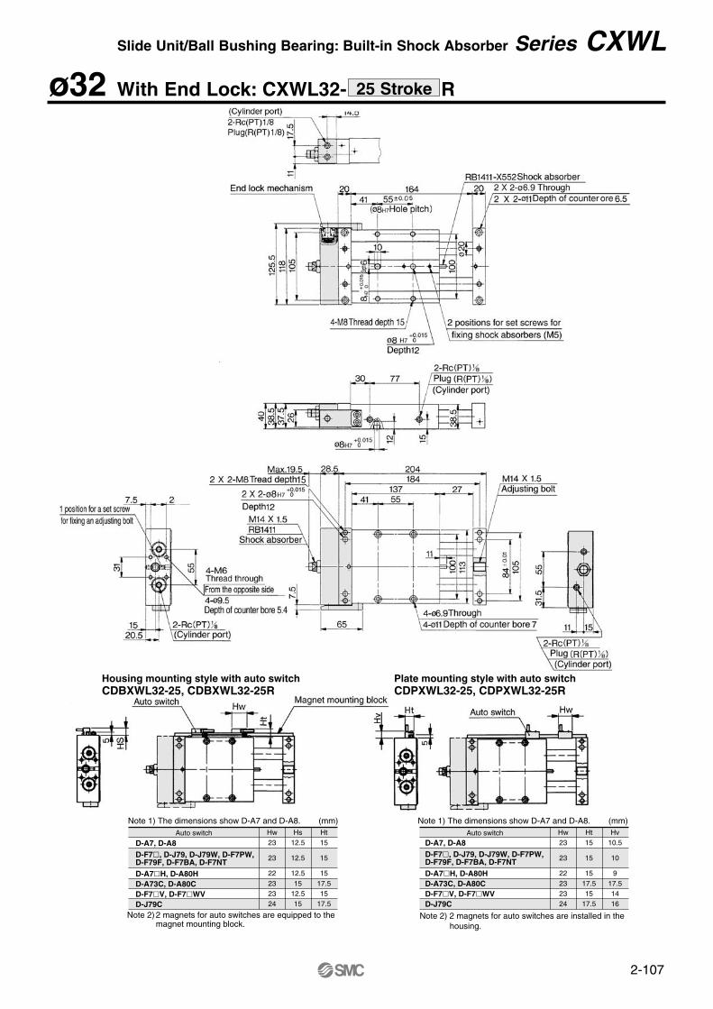
ø32 With End Lock: CXWL32- R25 Stroke
Slide Unit/Ball Bushing Bearing: Built-in Shock Absorber Series CXWL
Hw23
23
22232324
Hs12.5
12.5
12.515
12.515
Ht15
15
1517.515
17.5
Note 1) The dimensions show D-A7 and D-A8. (mm)
Note 2) 2 magnets for auto switches are equipped to the magnet mounting block.
Hw23
23
22232324
Ht15
15
1517.515
17.5
Hv10.5
10
917.51416
Note 1) The dimensions show D-A7 and D-A8. (mm)
Note 2) 2 magnets for auto switches are installed in the housing.
Housing mounting style with auto switchCDBXWL32-25, CDBXWL32-25R
Plate mounting style with auto switchCDPXWL32-25, CDPXWL32-25R
D-A7, D-A8D-F7, D-J79, D-J79W, D-F7PW, D-F79F, D-F7BA, D-F7NTD-A7H, D-A80HD-A73C, D-A80CD-F7V, D-F7WVD-J79C
Auto switch Auto switchD-A7, D-A8D-F7, D-J79, D-J79W, D-F7PW, D-F79F, D-F7BA, D-F7NTD-A7H, D-A80HD-A73C, D-A80CD-F7V, D-F7WVD-J79C
2-108
Applicable cylinder Auto switch
ø10, ø16, ø20ø25, ø32( )
Reed
switch
Solid
state
switch
D-A7/A8D-A7H/A80HD-A73C/A80CD-E7A/E80AD-F7/J79D-F7W/J79WD-F7FD-F7BALD-F7NTLD-F7VD-J79CD-F7WV
Electrical entry/Function
Grommet
Grommet
Connector
Grommet/Direct mounting
Grommet
Grommet/2 colour
Grommet
Grommet/Water resistant
Grommet/With timer
Grommet
Connector
Grommet/2 colour
Note 1) Only housing mounting ø10 is possible for the auto switches D-E7A and D-E80A.Note 2) Solid state switches are not mountable to the housing mounting ø10.Note 3) D-F7LF is not mountable to Series CDPXW.
Applicable auto switches
CXWM, CXWL
Series CXAuto Switch SpecificationsRefer to p.6-15 for further information on auto switches.