Embed Size (px)
Citation preview

Slide 1
APEX Task II Overview
Neil Morley for theAPEX Task II Participants
APEX E-Meeting
August 7, 2001

Slide 2
Overview
• Modeling- UCLA Codes- Hypercomp Phase II SBIR- Truchas with LANL
• Experiments- MTOR - FLIHY
• Other Work and Collaborations

Slide 3
New Modeling Work at UCLA
Complimentary 3D Formulations for Flow3D benchmarking and Task I analysis
A – Electric Potential Formulation
B – Induced Magnetic-Fields Formulation
Presented by Hulin Huang and Sergey Smolentsev
][2 BU ][ BUj
BUUBBt
B)()(
1 2
0
)'(
1
0Bj

Slide 4
• To convert HyPerComp’s existing adaptive hybrid unstructured mesh environment to problems in liquid metal MHD with free surfaces.• Modular code structure to the extent possible, for hierarchical MHD treatment• Interaction with interested research groups (LANL, LLNL, FZK, etc.)• Commercial applications to metallurgy (MAG/GATE: Concept Engineering Group, PA)
HyPerComp Phase-II SBIR Research
HIMAG : “HyPerComp Incompressible MHD( HyPEX) Adaptive Grid ” suite of codes
containing High Power Extraction code environment for nuclear fusion
CAD/Grid generation
Domain decomposition
PC-cluster based parallel computing

Slide 5
Summary of numerics
MHD models: Source term based models* B = constant, E = 0* B = constant, E = -* B varies along x
Integrated NS/Maxwell equations* Ideal MHD σ = * Real MHD
Heat transfer and turbulence* Conduction and radiation flux at free surface* Turbulence models
y
Bu
x
Bv zz
2
xm
zyx
xz
xyb
mxb
Bz
uB
y
uB
t
B
uz
BB
y
BBR
x
BRPu
t
u
2
2
22
Re
1
Re
1
/
Flow solver : Pressure-Implicit Splitting of Operators (PISO), R.I.Issa, 1985- A non-iterative pressure correction scheme, recently implemented on unstructured meshes for free surface flows (Ubbink and Issa, 1999, Imperial College, UK)
Free surface capture using Volume Of Fluid technique with higher order extensions ( Adaptive meshes, CIC-SAM, LANL procedures)Front tracking will be explored as an option
n ~(i,j)

Slide 6
Near-term Strategies
Engineering must take precedence over mathematical completeness due to the time-bound nature of this project. Programmatic consultations with technical groups will be pursued.
Mixed-analytical and numerical treatment of wall regions seem to hold promise for Hartmann number limitations. Parallel computations using hybrid meshes permit additional freedom in resolving Hartmann layers.
Boundary condition procedures in induced field formulations pose a variety of problems. A relative study of simple BC assumptions must be performed initially and guide future research
Elaborate implicit treatment must be available. At least:* Euler fully implicit* Crank-Nicholson* Hybrid, as in approx. projection methods of Kothe
At the end of approximately the first 6 months effort, UCLA’s involvement at the code level may be initiated.
Primary input from UCLA will be in the areas of MHD and interfacial transport* An independent investigation on the Hartmann number limitation + consequences* Advise on turbulence modeling issues* Models and boundary condition procedures for MHD

Slide 7
• Large Scale Parallelism– 1000+ CPUs– via domain decomposition– innovative solution algorithms
• Will use initially for:- studying circulation in droplets- test unstructured MHD models- compare with FLOW3D
Decomposition of partfor parallel computation
Collaboration with LANL on Truchas Code (Telluride)

Slide 8
• Incompressible Navier-Stokes Flow• Variable density owing to multiple fluids bounded by interfaces• Boussinesq approximation for density-temperature dependence• Multiple fluid, single-field model: multiple species per fluid• Turbulence: simple Prandtl mixing length model
• Fluid interfaces• Kinematics: volume tracking representation• Surface tension: volumetric force (normal and tangential)
• Interior “nonflow” regions• Voids• Conducting stationary solids: rigid and thermoelastic• Conducting moving solids (solidifying fluids)
• Heat transfer• Conduction, convection (radiative BCs)• Interior gap resistance• Liquid/solid phase change with micro-structural models
• Thermo-mechanical solid response (under development)• MHD: quasi-static approximation (just started!)
Physical Models in Telluride

Slide 9
Current Status M-TOR Facility Systems
• PPPL DC power supply and 24 coil torus tested up to 3000 A (B = 0.5 T). Trouble shooting underway to reach full 3600 A.
• Water coolant loop installed and tested. Over temperature sensing systems currently being installed
• Pumped flow loop nearly complete. Leak testing and flowmeter calibration to proceed this month.
• 16 L Ga-In-Sn alloy arrived from Russia and introduced to pressure-dispensed storage tank.
• Safety consultation with GA completed Ga-In-Sn flowing in open channel

Slide 10
MTOR – Arial View
1.4 m

Slide 11
EM Pumped Flow Loop for MTOR
•Collection Reservoir
•Electromagnetic Pump
•Storage Reservoir
•Heat Exchangers
•Main
•Bypass
•Coil support plate
•Magnet Coils

Slide 12
LM In @ Q = 0.05 l/s
LM Out
Positive Electrode
NegativeElectrodeFree Surface
Ultrasound Transducer
B
Preliminary Experiments for Inclined Plane Flow with Magnetic Propulsion
Bmax = 0.45 T
L = 45 cm

Slide 13
B = 0, I = 0 B = 0.5 – 0.2, I = 14A

Slide 14
6 7 8 9 10
Time-of-Flight (microsec)
I = 0 A
I = 14 A
h1 = 8.43 mm with no parallel current
h2 = 8.08 mm with 14 A parallel current (5.8 x 10⁴ A/m2)
h = 0.35 mm
Abscissa divisions: 0.548 mm/div
I = 14 A
I = 0 A
Ultrasound measurements indicate reduction in flow height

Slide 15
Visual observations
• Most surface waves disappear as field comes up. No large instabilities visible due to field gradient
• Remaining surface waves disappear and liquid level visibly decreases near inlet as current comes up.
• Rapid change in current splashed the liquid out of the channel

Slide 16
MTOR
Small inclined plane tests

Slide 17
New inclined plane test section
• Multiple, movable ultrasound height sensors
• Variable side wall position, inclination angle and inlet nozzle height
• Electrically isolated for applied current control (0-150A)

Slide 18
MHD Tests in NSTX conditions
Flux horns for field concentration (B=0.8 T) and
directional variation

Slide 19
MHD Tests of Soaker Hose for NSTX
• Preliminary schematic of first soaker hose test in MTOR
• 3 slotted tubes can be rotated as a block to change field orientation

Slide 20
Cryo-cooling of MTOR coil
N2 cooling of MTOR coil down to vapor temp of –45 C gave a factor of 2 drop in conductivity.

Slide 21
Current Status FLIHY Facility Systems
• Pumping station, flow meter and 4 m straight test section installed and operating
• IR heater system installed and operating (40 kW/m2)
• Ultrasound and IR camera diagnostics working, techniques continue to be evolved
• Dye injection system being redesigned
Water Film flowing under IR heater
Flow direction
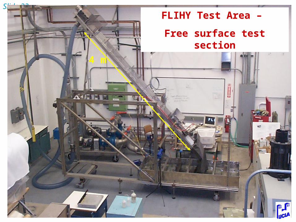
Slide 22FLIHY Test Area –
Free surface test section
4 m

Slide 23
FLIHY - Free surface test section
Flow direction~ 8 m/s

Slide 24
FLIHY Free surface test section
Shielded IR heaterFirst Experiments on Free Surface Turbulent Heat Transfer Underway
IR image of water surface emerging from IR heater section
IR study of surface cooling as a function of flow height, velocity
and inclination
Will be summarized by Sergey Smolentsev and Brent Freeze

Slide 25
Other work• Plasma wind tests in PISCES -
Collaboration with G. Antar and R. Doerner (UCSD)
• Modeling of DIII-D lithium sample movement – Collaboration with D. White and C. Wong (GA)
• FLIHY closed channel flow influence of MHD – Jupiter II collaboration with Japan
PISCESPlasmaColumn
PISCESPlasmaColumn
Flowing film and stagnant boat tests in PISCES