Embed Size (px)
Citation preview
Page 1 of 28
Hard copies of this document are for REFERENCE ONLY and should not be Considered the latest revision beyond the date of printing.
Author(s) Date
Jeffrey Tice
David Kiehl
Tom Nieland
REVISED
9-01-2010
SLAC ILC TTF3 COUPLER Build Number 21
Particle Physics & Astrophysics Document Title
TTF3 Coupler Assembly Process
Cold Part Serial
Numbers
Warm Part Serial
Numbers
Operators Dates
CP3C90 CP3H90 TN/MP 7-18-12
CP3C83 CP3H92 TN/MP 7-18-12
1. Change History Log
Revision Effective Date Description of Changes
1 08-04-2009 Capacitor / Waveguide Install Sequence
2 08-06-2009 Made Cleaning Process A Separate Document
3 08-25-2009 Added Acronym section
4 08-27-2009 Moved Parts List To A Bill Of Materials
5 09-08-2009 Torque Guidelines For Vacuum Components
6 09-15-2009 Data Sheet
2. Contents
1. Change History Log ..................................................................................... 1Error! Bookmark not defined.
2. Contents ....................................................................................................... 1Error! Bookmark not defined.
DATA SHEET (BUILD SUMMARY)......................................................................................3
Added 14.5 Run ion pumps a minimum of 24 hours 7 09-01-2010

Page 2 of 28
Hard copies of this document are for REFERENCE ONLY and should not be Considered the latest revision beyond the date of printing.
3. Scope………………………………………………………………………………………………………6
4. Applicable Documents ................................................................................................................................ 6
5. Acronyms…………………………………………………………………………………………6
6. Receiving TTF3 Couplers……………………………………………………………………..…7
7. TTF3 Coupler Cleaning Process…………………………………………………………………7
8. Coupler Processing Cavity Assembly SA-390-006-58…………………………………………….8
9. Cleaning of Cold Parts & Cold Transitions………………………………………………………9
10. Assembly of Cold Parts to CPC…………………………………………………………………..9
11. Cold Pumping Group Assembly to CPC Assembly……………………………………………..11
12. Cleaning of Warm Part………………………………………………………………………….12
13. Assembly of Warm Parts………………………………………………………………………...12
14. Leak Test of Couplers……………………………………………………………………………15
15. Moving Couplers from Clean room to ESB……………………………………………………15
16. End Station B Oven Bake Out………………………………………………………….……….17
17. Assembly of Wave Guide Housing to Coupler Assembly……………………………………..18
18. R.F. Cold Test / Test Results……………………………………………………………………21
19. Install R.F. Blankets, fiber optic sensor and TC's……………………………………………..22
20.. R.F. Test………………………………………………………………………………………...23
21. Post Test Inspection For Arcing……………………………….……………………………….24
22. Disassembly and inspection of the couplers for shipping………………………………………25

Page 3 of 28
Hard copies of this document are for REFERENCE ONLY and should not be Considered the latest revision beyond the date of printing.
BUILD NUMBER:21
RF IN WARM PART:
WARM PART P/N:
WARM PART COUPLER PORT I: CP3H90
WARM PART Assembly Date: 7-19-12
Helium Leak Test: 6.7 X 10⁻⁹
Ion Pump Vacuum Reading PRE-BAKE
OUT:
1.4 X 10⁻⁴
Ion Pump Vacuum Reading POST-
BAKE OUT:
1.8 X 10⁻⁶
Ion Pump Vacuum Reading Post R.F.
Test
7.2 X 10⁻⁶
CAPACITOR S/N: NEW DESIGN
Author(s) Date
Jeffrey Tice
David Kiehl
Tom Nieland
REVISED
09-01-2010
SLAC ILC TTF3 COUPLER Build Number 21
Particle Physics & Astrophysics Document Title
TTF3 Coupler Data Sheet

Page 4 of 28
Hard copies of this document are for REFERENCE ONLY and should not be Considered the latest revision beyond the date of printing.
RF IN COLD PART:
COLD PART P/N:
COLD PART COUPLER PORT I: CP3C90
COLD PART Assembly Date: 7-18-12
Helium Leak Test: 3.1 X 10⁻⁹
Ion Pump Vacuum Reading PRE-BAKE
OUT:
5.2 X 10⁻⁵
Ion Pump Vacuum Reading POST-
BAKE OUT :
2.2 X 10⁻⁶
Ion Pump Vacuum Reading Post R.F.
Test
2.1 X 10⁻⁶
RF OUT COLD PART:
COLD PART P/N:
COLD PART COUPLER PORT II: CP3C83
COLD PART Assembly Date: 7-18-12
Helium Leak Test: 3.1 X 10⁻⁹
Ion Pump Vacuum Reading PRE-BAKE
OUT:
5.2 X 10⁻⁵
Ion Pump Vacuum Reading POST-
BAKE OUT:
2.2 X 10⁻⁶
Ion Pump Vacuum Reading Post R.F.
Test
2.1 X 10⁻⁶
RF OUT WARM PART:
WARM PART P/N:
WARM PART COUPLER PORT II: CP3H92
WARM PART Assembly Date: 7-19-12
Helium Leak Test: 6.1 X 10⁻⁹
Ion Pump Vacuum Reading PRE-BAKE
OUT:
4.8 X 10⁻⁵
Ion Pump Vacuum Reading POST-
BAKE OUT:
2.6 X 10⁻⁶
Ion Pump Vacuum Reading Post R.F.
Test
7.5 X 10⁻⁶
CAPACITOR S/N: NEW DESIGN
Page 5 of 28
Hard copies of this document are for REFERENCE ONLY and should not be Considered the latest revision beyond the date of printing.
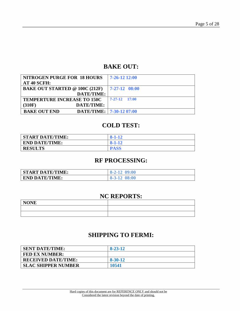
BAKE OUT:
NITROGEN PURGE FOR 18 HOURS
AT 40 SCFH:
7-26-12 12:00
BAKE OUT STARTED @ 100C (212F)
DATE/TIME:
7-27-12 08:00
TEMPERTURE INCREASE TO 150C
(310F) DATE/TIME:
7-27-12 17:00
BAKE OUT END DATE/TIME: 7-30-12 07:00
COLD TEST:
START DATE/TIME: 8-1-12
END DATE/TIME: 8-1-12
RESULTS PASS
RF PROCESSING:
START DATE/TIME: 8-2-12 09:00
END DATE/TIME: 8-3-12 08:00
NC REPORTS: NONE
SHIPPING TO FERMI:
SENT DATE/TIME: 8-23-12
FED EX NUMBER:
RECEIVED DATE/TIME: 8-30-12
SLAC SHIPPER NUMBER 10541
Page 6 of 28
Hard copies of this document are for REFERENCE ONLY and should not be Considered the latest revision beyond the date of printing.
3.0 Scope
This document describes the assembly of the TTF3 Coupler and its assemblies. It captures all
assembly requirements associated with assembly of the TTF3 Coupler.
4. Applicable Documents
[1] TESLA-COU-TTF3-ASSEM, “List of Preparation and Assembly Operations for Two TTF3
Couplers on their Test Bench” 16-05-2005
SLAC TTF3 Coupler Cleaning Process
Bill Of Materials
Torque Guidelines For Vacuum Components
5. Acronyms
B.O.M. Bill Of Materials
C. Centigrade / Celsius
CF Con Flat
C.P.C. Coupler Processing Cavity
E.S.B. End Station B (R.F. Test Facility)
F. Fahrenheit
MM. Millimeter
O.D. Outer Diameter
O.F.H.C. Oxygen Free H----- Copper
N.C. Non Conformance
NPT National Pipe Thread
Continued Next Page

Page 7 of 28
Hard copies of this document are for REFERENCE ONLY and should not be Considered the latest revision beyond the date of printing.
P/N. Part Number
P.S. Power Supply
P.S.A. Pressure Sensitive Adhesive
P.T.F.E. Polytetrafluoroethylene, (Pipe Thread Teflon Tape)
R.F. Radio Frequency
R.T.V. Room Temperature Vulcanizing
S/N. Serial Number
SS. Stainless Steel
T/C Thermo Couple
T.B.D. To Be Determined
U.H.V. Ultra High Vacuum
U.P.W. Ultra Pure Water
6. Receiving TTF3 Couplers
Use clean room gloves when handling all parts. Parts are received at Bldg. 33. Move crates to a
clean area to inventory against the Bill Of Materials. Note any missing parts and any additional
parts required for build up. Visually inspect parts for any damage and cleanliness. Put all parts
that do not go through the metrology inspection into clean room bins and move to Bldg. 6
clean room for cleaning. Any parts that will not be cleaned immediately will be stored in the
nitrogen purge cabinets at bldg. 6. The warm parts and cold parts will remain at bldg. 33 clean
room for additional metrology inspection. After metrology inspection is complete, place parts in
clean room bins and transport to bldg. 6 for cleaning.
7.0 TTF3 Coupler Cleaning Process
Refer to TTF3 Coupler Cleaning Process Document.

Page 8 of 28
Hard copies of this document are for REFERENCE ONLY and should not be Considered the latest revision beyond the date of printing.
8.0 Coupler Processing Cavity Assembly SA-390-006-58
8.1 Assembly of CPC is done by placing bottom flange (PF-390-006-65) on CPC assembly stand
with cavity facing up.
8.2 Visually inspect knife edges for a clean and sharp interface. Edge should be free of nicks and
deformities.
8.3 Using class 10 alcohol wipe, clean and visually inspect copper gasket (part # MDC 191022)
for any nicks and deformities. Place gasket onto gland of CPC
8.4 Install cleaned dust covers caps over 3 flanges and install nitrogen purge blank off to Vacuum
Port II of item 1 top flange weldment.
8.5 Connect nitrogen purge and start flowing, mate top flange weldment item 1 (SA-390-006-59)
onto bottom flange (PF-390-006-65) making sure copper gasket does not move during mating
process.
8.6 With nitrogen purge flowing, assemble finger tight in mounting ear locations per SA-390-006-
58, using hardware the two hole dog ears go to Coupler Port II end. See figure 1 for reference.
Figure 1 (CPC assembly SA-390-006-58)
Coupler Port I
Coupler Port II
Coupler Port I Vacuum Port I
Vacuum Port II

Page 9 of 28
Hard copies of this document are for REFERENCE ONLY and should not be Considered the latest revision beyond the date of printing.
8.7 With nitrogen purge flowing, install remaining fasteners into CPC assembly per SA-390-006-
58
8.8 With nitrogen purge flowing, torque fasteners in a star pattern to 5 ft-lbs.
8.9 With nitrogen purge flowing, install CPC into the coupler integration stand
8.10 With nitrogen purge flowing, torque hardware per torque guidelines.
8.11 With nitrogen purge flowing, Invert coupler integration stand. Torque all CPC hardware as
needed to final torque at this time.
8.12 If you are not installing the cold part of the coupler at this time then cover all open ports on the
CPC. Then remove the nitrogen purge and cap the purge port.
9 Cleaning of Cold Parts & Cold Transitions
See SLAC TTF3 Cleaning Process
10.0 Assembly of Cold Parts to CPC
10.1 Blow with filtered ionized nitrogen (P= 4 bars or 60 psi) on each cold parts:
Note: In each position of each part, the count must be below 10 particles of 0.3
microns per cubic foot (i.e. per minute) If, after 5 minutes of blowing, there are still
greater then 10 particles, the parts goes back to cleaning process.
10.2 Place CPC (SA-390-006-58) from class 100 storage area into the class 10 work bench area.
Carefully remove dust covers from cold coupler ports (8 holed ports viewed at 12 and 6
clocked).

Page 10 of 28
Hard copies of this document are for REFERENCE ONLY and should not be Considered the latest revision beyond the date of printing.
10.3 Place CPC (SA-390-006-58) from class 100 storage area into the class 10 work bench area.
Carefully remove dust covers from cold coupler ports I & II Do a particle count at each port.
10.4 Install 6mm X 40mm nitronic 60 studs & nuts into Coupler Ports I & II.
10.5 Invert stand to normal configuration
10.6 Install aluminum vacuum gasket onto cold part assembly. Make sure gasket it is free of nicks
& scratches for a proper vacuum seal.
10.7 Delicately place cold part into position on Coupler Port I flange. Make sure the e pick-up port
of the cold part is facing toward the outside edge of the CPC per photo above.
10.8 Install all (8) Nitronic 60 6mm nuts onto cold part and tighten in a torque pattern
Note cold part serial number here: ____CP3C90_______
10.9 Install aluminum gasket onto coupler port II flange. Make sure gasket it is free of nicks &
scratches for a proper vacuum seal.
10.11 Delicately place cold part from support stand onto Coupler Port II flange. Make sure the e
pick-up port of the cold part is facing towards the outer edge of CPC per photo above.
10.12 Install all (8) Nitronic 60 6mm nuts onto cold part and tighten in a torque pattern
Page 11 of 28
Hard copies of this document are for REFERENCE ONLY and should not be Considered the latest revision beyond the date of printing.
Note cold part serial number here:____CP3C83
10.13 Examine the knife edge on the E-Pickup Port of each cold part. Verify gasket surface is free of
nicks & scratches for a proper vacuum seal.
10.14 Examine the knife edge on the E-Pickup to be installed on each cold part. Verify gasket
surface is free of nicks & scratches for a proper vacuum seal.
10.15 Examine the copper seal for each E – Pickup. Verify gasket surface is free of nicks & scratches
for a proper vacuum seal.
10.16 While maintaining a nitrogen purge place a clean copper gasket on one of the ports and install
E- Pickup on cold part with Hexagonal Bolt w/ Duo-Nut fastener kits. Then repeat the same
process for the second E-Pickup port.
10.17 Inspect knife edge of VAC Port I. Inspect and install VAT gate Valve in the open position. If
pump assembly is not going to be installed at this time, then inspect knife edges and install a
blank off.
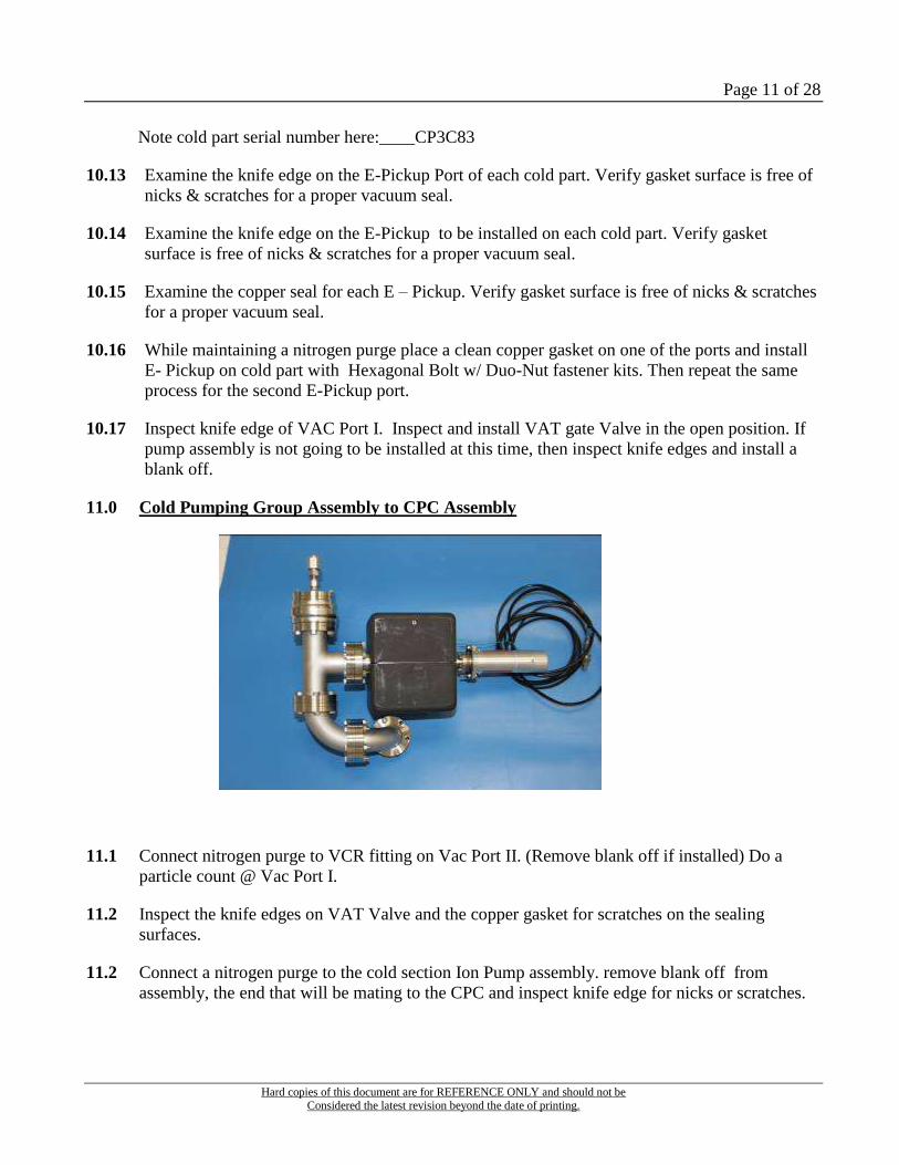
11.0 Cold Pumping Group Assembly to CPC Assembly
11.1 Connect nitrogen purge to VCR fitting on Vac Port II. (Remove blank off if installed) Do a
particle count @ Vac Port I.
11.2 Inspect the knife edges on VAT Valve and the copper gasket for scratches on the sealing
surfaces.
11.2 Connect a nitrogen purge to the cold section Ion Pump assembly. remove blank off from
assembly, the end that will be mating to the CPC and inspect knife edge for nicks or scratches.

Page 12 of 28
Hard copies of this document are for REFERENCE ONLY and should not be Considered the latest revision beyond the date of printing.
11.3 Do a particle count on the pump assembly. If assembly meets particle requirements, then
disconnect nitrogen purge from the Ion Pump and install assembly onto vacuum port I while a
nitrogen purge is connected and flowing @Vac Port II.
12.0 Cleaning of Warm Part
Refer to TTF3 Coupler Cleaning Process Document.
13.0 Assembly of Warm Parts
Install purge port on the vacuum CF16 window
flanged. Set purge at 3 psi
Coupler Port I __CP3H90 Coupler Port II____CP3H92
Install Nitronic 60 antenna screw in to warm part center coax.
13.1 Place CF100 copper gasket onto Cold part CF flange.
13.2 Do a particle count on the ceramic and copper areas of the cold part and the copper cavity of the
warm part.
13.3 After acceptable particle count is achieved. One person to hold and position warm part over the
cold part, while the other person inserts the antenna screw allen wrench. Verify alignment is
correct with respect to CF16 port alignment. (per diagram on page 11) Thread antenna screw into
hole of the cold part until flush, then back off half a turn.
13.2 Install all 8 mm bolts to hand tight only. Then tighten antenna screw.
13.3 Mount support plates to warm part and to the coupler stand.
13.4 Verify the cold part bellows protectors are tight, Use torque support tool when tightening the 8
mm to counter act the torque force when tightening hardware. With torque support tool in the
proper position, tighten the 8mm Nitronic 60 bolts (CF100 Flange) on Warm part.
See Photo of torque tool below.

Page 13 of 28
Hard copies of this document are for REFERENCE ONLY and should not be Considered the latest revision beyond the date of printing.
13.5
13.6 Install springs to RF Antenna. Mount the RF springs on tuning rods (bend last spring end 90
from existing configuration on both ends then place one end into the other for fastening). Test
of inserting the rods into warm parts to make sure that the springs don’t move.
13.7 Install copper gaskets to top of warm part, then install tuning rod. Be sure to turn tuning rod 90
degrees for insertion of tuning pin at coax end. Hole alignment is done by pushing down on
tuning rod and moving slowly to align through holes. Torque to just over hand tight using
10mm socket.
13.8 Before Proceeding Verify Proper Antenna Rod Engagement
13.9 Install e-pickups on warm parts (one blank-offs on the top port opposite of bottom e-pickup) e-
pickup on the top and bottom ports of warms parts are inline vertically with each other.
Note: All CF16 ports may not be mated at a metal to metal. (copper gasket may be
visible).
13.8 Do a particle count on both Ion Pump Assemblies for the warm Parts
13.9 With a nitrogen purge flowing Install Ion Pump Assemblies to both warm parts per orientation
in sketch below.
13.10 Install Ion Pump Support Rods to the coupler stand
Page 14 of 28
Hard copies of this document are for REFERENCE ONLY and should not be Considered the latest revision beyond the date of printing.
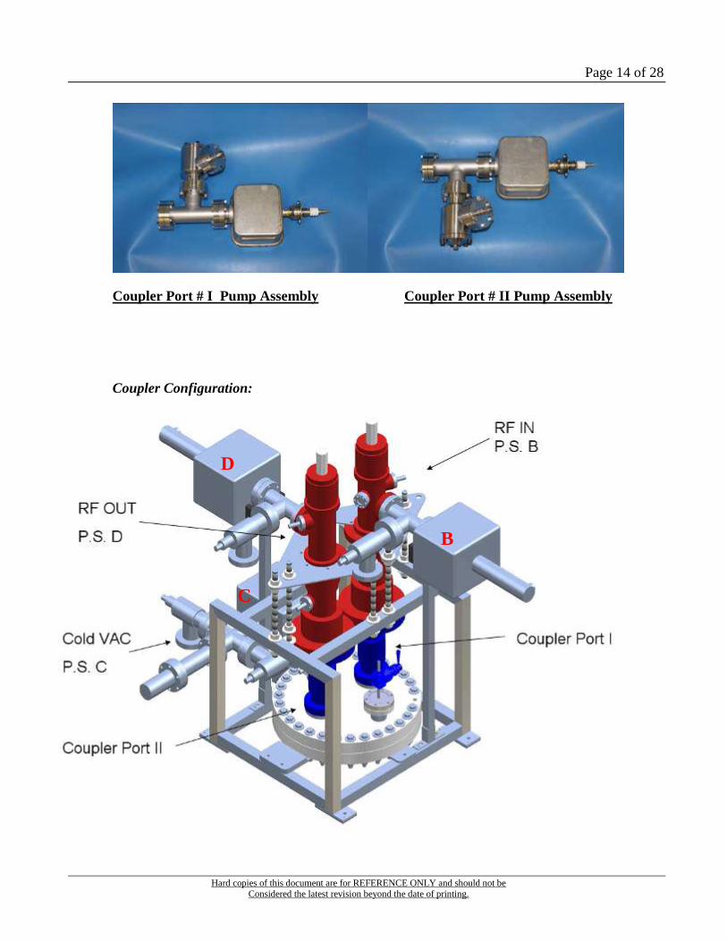
Coupler Port # I Pump Assembly Coupler Port # II Pump Assembly
Coupler Configuration:
B
D
C

Page 15 of 28
Hard copies of this document are for REFERENCE ONLY and should not be Considered the latest revision beyond the date of printing.
14.0 Leak Test of Couplers
Set up the leak detecter at building 006 cleanroom class 100 outside wall at feed-through
vacuum port.
Note: Be sure that during vacuum hook-up a positive pressure of Nitrogen is on the system
at all times to keep particle count low.
14.1 Start with Cold vacuum section first.
14.2 Open the value on the detector and pump down until a base pressure of TBD Torr is obtained
from the detector to the CPC Cold valve.
14.3 Slowly open the CPC Cold valve in the class 10 area. Pump down until a base pressure of TBD
Torr on Cold Assembly pumping system is reached.
14.4 Start the helium leak detection using the helium gas blower set at a minimum flow rate and start
at CPC Con Flat flange to Cold parts. Blow helium around the Con Flat flange in a slow
circular motion at each gasket and joint area. If no leak is detected, then apply power to that
sections Ion Pump. Close gate valve to isolate the couplers from the leak detector. Vent leak
detector disconnect and cap the VCR fitting.
14.5 Ion pumps are to run for a minimum of 24 hours before moving couplers to End Station
B.
14.6 Repeat the same process for each section that will be under vacuum.
_______________________________________________________________________
15.0 Moving Couplers from Cleanroom to ESB
15.1 Prepare oven box and hydraulic lifting platform to receive pumped down coupler pair.
15.2 Do a visual inspection of the lift platform and oven box. Look for damage to the gasket
Galled hardware, the wheels on the oven box. Fluid leaks, missing hardware, control
mechanisms function smoothly, that the lift platform operates properly etc. no surprises.
15.3 Do an alcohol wipe down on the hydraulic lifting platform and move it into the gowning
area.
15.4 Take the lid off of the oven box and do an alcohol wipe down on the rolling base. Position
the base on the lift platform in the correct orientation. Then clamp it to the platform.
15.5 Do a complete alcohol wipe down inside and outside of the lid of the oven box.
15.6 Verify that there is no damage to the ion pump bulkheads or panel.
15.7 Review: thermocouple locations are identified and correctly labeled.

Page 16 of 28
Hard copies of this document are for REFERENCE ONLY and should not be Considered the latest revision beyond the date of printing.
15.8 Turn off ion pump power supplies. Disconnect cables at the power supply.
15.9 Route cables for the oven box.
15.10 Remove all non bake able materials from coupler stand and coupler assemblies (
protective covers for ceramic windows etc.)
15.11 Move coupler assembly test frame onto the base of the oven box. In the correct test
orientation. Bolt the frame to the base.
Vacuum System CPC Location Power Supply at ESB T/C Location &
Number
RF In Coupler Port I B #1- Coupler Port I Flange
Cold Coupler Port I & II C #2- Coupler Port I, Warm
Part, Upper E- Pickup
RF Out Coupler Port II D #3- Mid Air Between the
Ceramic Windows of the
Warm Parts
#4- Outside Purge Box
Inside Oven
Page 17 of 28
Hard copies of this document are for REFERENCE ONLY and should not be Considered the latest revision beyond the date of printing.
15.12 Attach thermocouples to the designated locations
15.13 Connect ion pump cables to there designated locations on the bulkhead.
15.14 Install the lid of the oven box and secure all fasteners.
15.15 Move the box and platform to the transport vehicle. Raise the platform to match the
height, of the bed, of the transport vehicle. Position platform to transfer the box, lock the
wheels, remove the clamps that secure the box to the platform, then gently roll the box on
to the transport vehicle.
15.16 Secure oven box with moving straps, and transport couplers to End Station B.
15.17 At End Station B position lift platform, apply the brakes, and raise platform to receive
the oven box.
16.0 End Station B Oven Bake Out
16.1 Roll the oven box onto the lift platform, install hardware in pre-drilled holes to secure the
box. (Note the wheel locations on the box in relation to the platform.) Lower the platform
and move couplers to the oven location.
16.2 Do an alcohol wipe down on the inside of the oven, inspect ion pump cables,
thermocouples, and nitrogen purge lines. Route cables, TC’s, and purge lines so the box can
be installed into the oven.
16.3 Raise the lift platform to match the height of the oven. Remove the hardware that is
securing the box to the platform. Move the box into the oven. Connect Ion Pumps and
Thermocouples per information on page 11.
16.4 Connect nitrogen purge lines and start the nitrogen purge
16.5 Turn on the ion pump power supplies.
16.6 Purge couplers until the oxygen is evacuated ( 5 – 24 hrs depending on flow rate)
16.7 Verify the oven monitoring systems are on and functioning properly.
16.8 Turn on the oven and oven blower. Set the initial temperature @ 100C / 212F
16.9 The Test Conductor will determine when to change the oven temp. from 100c to 150C
(305F). When the temp stabilizes, bake couplers for 24 hours.

Page 18 of 28
Hard copies of this document are for REFERENCE ONLY and should not be Considered the latest revision beyond the date of printing.
16.10 After 24 hours turn the oven off, leave the blower and the purge on and let the couplers
cool to ambient temperature.
BUILD 21 BAKE RESULTS

Page 19 of 28
Hard copies of this document are for REFERENCE ONLY and should not be Considered the latest revision beyond the date of printing.
17.0 Assembly of Wave Guide Housing to Coupler Assembly
Using clean room gloves pull all parts for assembly of Waveguide parts from storage lockers.
Note all quantities pulled. Visually inspect for any non-UHV cleanliness on all parts (i.e. oil,
grease, non-lint free paper, metallic dust). Have any parts re-cleaned ?
17.1 Assemble waveguide housing (Item 3 P/N DESY1044624A000. Install 2 male connectors (Item
12 P/N S101516) and the two modified brass plugs for light monitoring into the NPT threaded
holes on the back end of the waveguide assembly
Do not use any RTV or PTFE tape.
17.2 Install ceramic protective cover over warm window, be very careful not mark
ceramic. Be sure not to have any tape PSA material touch the window.
17.3 Install waveguide assembly (Item 3 P/N DESY1044624A000) onto warm coupler part. Make sure
waveguide is positioned correctly with respect to waveguide flange.Note: Be extremely carful on
lowering the wave guide assembly onto warm coupler part.

Page 20 of 28
Hard copies of this document are for REFERENCE ONLY and should not be Considered the latest revision beyond the date of printing.
17.4 Install waveguide clamp rings (Item 4 P/N DESY3044624001) using M4 X 10 screws (Item
10 P/N S100456) and M4.3 washers (Item 11 P/N S100464). Clamp rings “U” channel faces up into the
waveguide assembly. Make sure waveguide is aligned correctly for orientation (90º from N
17.5 Remove ceramic protective cover piece from warm coupler part.
17.6 Install the capacitor assembly (Item 7 P/N RDESY2988356F000), deep end of capacitor fits into
the waveguide and warm coupler part, using the M3 x 8 Screws (Item 9 P/N S100447) Center
capacitor assembly on waveguide ring. Install all capacitor hardware loose. First tighten the 8
screws from the capacitor to the waveguide assembly. Next tighten remaining capacitor
hardware. Then torque the clamp ring hardware.
17.7 Insert adjustable mechanical handle (Item 1 P/N DESY3988356G000) into top part of warm
coupler. Thread into tuning rod until it dead ends, back up ½ turn. Remove handle from
adjustable mechanical handle. Install screws M4x10mm 316 SST (Item 10 P/N S100456 or Item
17 P/N Grainger P/N 6DB28 or S100456) into the top of warm coupler part. Leave loose. (see
sketch below)
17.8 Cut 15 inches off high voltage cable (Item 5 P/N 379126) for use. Crimp lug (Item 18 P/N
SLAC Stores 039268 or AMP 34123) to one end of wire. Tin both ends of wire, solder cup on
the high voltage bushing (Item 13 P/N S101518) and the crimp lug (Item 18 P/N SLAC Stores
039268 or AMP 34123). Solder together. Clean off all solder flux.
17.9Install socket (Item 15 P/N DESY40446240004) and the high voltage bushing (Item 13 P/N
S101518) into waveguide cover offset hole (Item 2 P/N DESY30446240002). Torque. (see
sketch below)
17.10 Remove one screw from adjustable mechanical handle. Install lug end of wire onto the warm
coupler end and install screw and torque all hardware. Install waveguide cover plate (Item 2 P/N
DESY30446240002) onto waveguide (coil wire inside making sure not to pinch the wire) using
fasteners (Item 8 P/N S100476). Torque to hand tight. Install handle for tuning rod (leave gap
between the tuning handle and cover plate). (see sketch below)

Page 21 of 28
Hard copies of this document are for REFERENCE ONLY and should not be Considered the latest revision beyond the date of printing.
17.11 Install custom grounding cable from the High Voltage Bushing to a phillips head screw on the
cover plate.
17.12 Verify all holes in the waveguide are filled or covered (for R.F. leaks)
17.13 Remove cold parts bellows support flanges (only the clam shells) from both cold parts. Make
sure cold parts are able to move with out any obstruction
18.0 R.F. Cold Test
18.1 Call Chris Nantista x4906 for cold testing. Perform Cold Test.
17.9 17.10 17.7

Page 22 of 28
Hard copies of this document are for REFERENCE ONLY and should not be Considered the latest revision beyond the date of printing.
18.2 Record cold test data
|S11| = -74.5dB|S22| = -48.1dB
|S12| = -0.118dB|S21| = -0.124dB
COLD TEST – 2012/08/03
The tuning data is measured with an Agilent 8719ES S-Parameter Network Analyzer.

Page 23 of 28
Hard copies of this document are for REFERENCE ONLY and should not be Considered the latest revision beyond the date of printing.
19.0 Prepare Couplers For R.F. test
19.1 Install TC’s (see photo for locations)
19.2 Install R.F. absorption material to locations determined by Faya Wang on coupler test
article reduce R.F. signal to a level that is set by Safety Director at End Station B.
TC #1 WARM PART
R.F. IN
TC #2 COLD PART
R.F. IN
TC #4 WARM PART
R.F. OUT
TC #3 COLD PART
R.F. OUT

Page 24 of 28
Hard copies of this document are for REFERENCE ONLY and should not be Considered the latest revision beyond the date of printing.
20.0 L Band R.F. Test
RF PROCESS HISTORY FOR VACUUM

Page 25 of 28
Hard copies of this document are for REFERENCE ONLY and should not be Considered the latest revision beyond the date of printing.
RF PROCESS HISTORY FOR E-PROBE AND PMT
21.0 Post Test Inspection for Arcing
21.1 Verify test is completed.
21.2 Verify the power to the beam line has been locked out and tagged.
21.3 Verify nitrogen purge is off and pressure is bled off to ambient
21.3 Remove the couplers from the beam line test configuration at the waveguide flange.
21.4 Look at the ceramic windows and waveguides for signs arcing. Note any findings.
21.5 Remove antenna adjustment knob, waveguide cover plate.
21.6 Remove the capacitor and waveguide and do a thorough inspection of capacitor,
waveguide, and ceramic windows for arcing. If there is indications of arcing, write a
Page 26 of 28
Hard copies of this document are for REFERENCE ONLY and should not be Considered the latest revision beyond the date of printing.
Non-Conformance Report. And forward information to Chris Adolphsen, Faya Wang,
and Jeff Tice for review.
21.7 Turn off power to the Ion Pumps and disconnect cables
21.8 Install bellows support fixtures onto the cold parts
21.8 Install cover to transport couplers to bldg. 6
22.0 Post test disassembly and inspection
NOTE: Clean Room Alcohol may be use for a lubricant for screws, nuts, and bolts where applicable
during disassembly
22.1 Move assembly to building 6
22.2 Wipe down and get into gowning area
22.3 Remove oven box cover
22.4 Wipe down couplers
22.5 Remove 4 bolts holding the coupler stand to the bottom of the oven box.
22.6 Move couplers to Class 10 cart Put oven box back together and push out of gowning
area.
22.7 Move couplers into class 100 area
22.8 Wipe down couplers again
22.9 Blow of with Nitrogen
22.10 Remove 3 ion pump stingers and store. Phillips screw driver
22.11 Remove Ion pump magnets and store. Wipe down pumps. 2.5MM Hex
22.12 Blow of with Nitrogen
22.13 Close CPC Gate Valve
22.14 Hook up pump cart with a nitrogen purge to the VCR fitting on the warm part pump
assembly.
22.15 Pump down to equalize the vacuum pressure on both sides of the gate valve.

Page 27 of 28
Hard copies of this document are for REFERENCE ONLY and should not be Considered the latest revision beyond the date of printing.
22.16 Open valve slowly, then back fill with nitrogen through the pump cart to bring warm
part to atmosphere pressure.
22.17 With the nitrogen purge flowing (under pressure) remove Ion pump assembly.
22.18 Cap pump assembly and move it to the storage rack to be recertified at a later date
(clean, particle counted, etc.)
22.19 Install blank-off with VCR fitting to warm part CF25 flange.
22.20 Attach filtered nitrogen purge (with VCR fitting) to the warm part and remove antenna
adjustment rod.
22.21 Remove all but 2 of the 8mm bolts (opposite sides from each other) that attach the warm
part to the cold part.
22.22 Remove the antenna screw from the warm part antenna connection. Bag and tag for
shipping.
22.23 Remove warm part fixture supports from the test fixture.
22.24 With one person supporting the warm part ( bellows ) remove the last two 8mm bolts
and separate the warm part from the cold part. Bag and tag bolts for shipping.
22.25 With the purge still flowing do a particle count. Set warm part CF 100 flange on a
support stand in a vertical position over the particle counter and do a particle count. When
acceptable particle count is achieved, install antenna adjustment rod and the shipping blank-off
with the antenna support spacer.
22.26 Install bellows support rods and ceramic protection cover disconnect nitrogen purge and
cap the VCR fitting.
22.27 Do a final wipe down and particle count of warm part exterior.
22.28 Triple vacuum bag with nitrogen purge for shipping and place into warm part coupler
shipping container.
22.29 Do a particle count on the exposed end of the cold part.
22.30 Install top hat with a nitrogen purge.
22.31 Repeat sequences 22.14 through 22.29 for removal of remaining warm part.
22.32 Verify CPC gate valve is closed. Connect pump cart with a nitrogen purge to the cold
part ion pump assembly at the VCR fitting.
22.33 Pump down to equalize the pressure on both sides of the gate valve.

Page 28 of 28
Hard copies of this document are for REFERENCE ONLY and should not be Considered the latest revision beyond the date of printing.
22.34 Slowly open the valve, while venting with nitrogen through the pump cart.
22.35 Remove cold part pump assembly at the CPC gate valve. Cap pump assembly and place
on storage rack the be recertified at a later date. (cleaned, particle counted, etc.)
22.36 Install a blank-off with a VCR fitting onto the CPC gate valve with a nitrogen purge.
22.37 Remove purge and cap VCR fitting for shipping.
22.38 Do a final wipe down and particle count of cold part section exterior.
22.39 Install Top Hat Per drawing below.
22.40 Triple vacuum bag with a nitrogen purge. And place into cold section shipping container.