Embed Size (px)
Citation preview

The Flow Resource
FTI Flow Technology, Inc.8930 South Beck Avenue, Suite 107
Tempe, Arizona, USA 85284 Phone: 480-240-3400 • Fax: 480-240-3401
[email protected] • www.ftimeters.com
SL9000Flow Computer for
Rate, Total, and Batching Applications
99613 02/20/07
SAFETY INSTRUCTIONSThe following instructions must be observed.
• This instrument was designed and is checked in accordance with regulations in force EN 60950 (“Safety of informationtechnology equipment, including electrical business equipment”).A hazardous situation may occur if this instrument is not used for its intended purpose or is used incorrectly. Please noteoperating instructions provided in this manual.
• The instrument must be installed, operated and maintained by personnel who have been properly trained. Personnel mustread and understand this manual prior to installation and operation of the instrument.
• This instrument is internally fused. Replace the internal fuse with the following specified type and rating only:Input Power Recommended Fuse
115 VAC 160 mA slow blow fuse230 VAC 80 mA slow blow fuse
12-24 VDC 800 mA slow blow fuse
Disconnect power supply before replacing fuse!
• The manufacturer assumes no liability for damage caused by incorrect use of the instrument or for modifications or changesmade to the instrument.
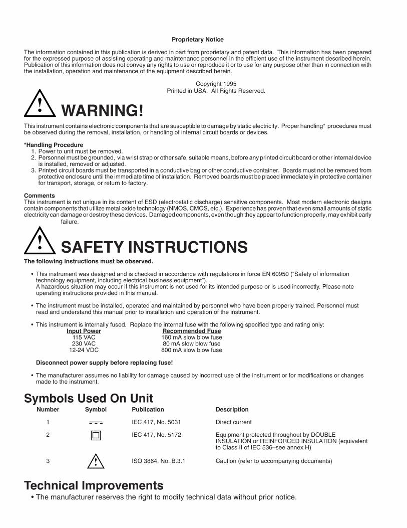
Symbols Used On UnitNumber Symbol Publication Description
1 IEC 417, No. 5031 Direct current
2 IEC 417, No. 5172 Equipment protected throughout by DOUBLEINSULATION or REINFORCED INSULATION (equivalentto Class II of IEC 536–see annex H)
3 ! ISO 3864, No. B.3.1 Caution (refer to accompanying documents)
Technical Improvements• The manufacturer reserves the right to modify technical data without prior notice.
Proprietary Notice
The information contained in this publication is derived in part from proprietary and patent data. This information has been preparedfor the expressed purpose of assisting operating and maintenance personnel in the efficient use of the instrument described herein.Publication of this information does not convey any rights to use or reproduce it or to use for any purpose other than in connection withthe installation, operation and maintenance of the equipment described herein.
Copyright 1995Printed in USA. All Rights Reserved.
WARNING!This instrument contains electronic components that are susceptible to damage by static electricity. Proper handling* procedures mustbe observed during the removal, installation, or handling of internal circuit boards or devices.
*Handling Procedure1. Power to unit must be removed.2. Personnel must be grounded, via wrist strap or other safe, suitable means, before any printed circuit board or other internal device
is installed, removed or adjusted.3. Printed circuit boards must be transported in a conductive bag or other conductive container. Boards must not be removed from
protective enclosure until the immediate time of installation. Removed boards must be placed immediately in protective containerfor transport, storage, or return to factory.
CommentsThis instrument is not unique in its content of ESD (electrostatic discharge) sensitive components. Most modern electronic designscontain components that utilize metal oxide technology (NMOS, CMOS, etc.). Experience has proven that even small amounts of staticelectricity can damage or destroy these devices. Damaged components, even though they appear to function properly, may exhibit early
failure.
!
!
1. DESCRIPTION
1.1 Unit Description ........................................................................................................................... 11.2 Unit Features ............................................................................................................................... 11.3 Specifications .............................................................................................................................. 2
2. INSTALLATION
2.1 General Mounting Hints ............................................................................................................... 62.2 Mounting Diagrams ..................................................................................................................... 6
3. APPLICATIONS
3.1 Liquid Volume .............................................................................................................................. 73.2 Batching ....................................................................................................................................... 8
4. WIRING
4.1 Typical Batcher Wiring ................................................................................................................. 94.2 Typical Rate/Total Wiring ............................................................................................................. 9
5. UNIT OPERATION
5.1 Front Panel Operation Concept for Run Mode .......................................................................... 105.2 General Operation ..................................................................................................................... 115.3 Ratemeter/Totalizer Operation ................................................................................................... 11
5.3.1 Password Protection for Rate/Total mode ................................................................ 115.3.2 Relay Operation in Rate/Total mode ........................................................................ 115.3.3 Pulse Output in Rate/Total mode ............................................................................. 115.3.4 Analog Output in Rate/Total mode ........................................................................... 115.3.5 RS-232 Serial Port Operation in Rate/Total mode .................................................. 125.3.6 RS-485 Serial Port Operation in Rate/Total mode .................................................. 12
5.4 Batcher Operation ..................................................................................................................... 135.4.1 Batcher Configuration .............................................................................................. 135.4.2 Password Protection for Batcher mode .................................................................... 145.4.3 Relay Operation in Batcher mode ............................................................................ 145.4.4 Pulse Output in Batcher mode ................................................................................ 145.3.5 Analog Output in Batcher mode .............................................................................. 145.4.6 RS-232 Serial Port Operation in Batcher mode ...................................................... 155.4.7 RS-485 Serial Port Operation in Batcher mode ...................................................... 15
6. PROGRAMMING
6.1 Front Panel Operation Concept for Program Mode ................................................................... 166.2 EZ Setup .................................................................................................................................... 176.3 Setup Menus ............................................................................................................................. 186.4 Setup Sub-Menus ...................................................................................................................... 19
6.4.1 SELECT EZ SETUP ................................................................................................. 196.4.2 INSTRUMENT TYPE ............................................................................................... 196.4.3 SETUP INDICATORS (Total) ................................................................................... 216.4.4 SETUP INDICATORS (Rate) ................................................................................... 216.4.5 SETUP FLOW INPUT (Pulse - chA & chA=chB) ...................................................... 226.4.6 SETUP FLOW INPUT (Pulse - Quadrature, Qx1 or Qx2) ........................................ 236.4.7 SETUP PULSE OUTPUT ......................................................................................... 246.4.8 SETUP ANALOG OUTPUT ...................................................................................... 256.4.9 SETUP RELAYS ...................................................................................................... 256.4.10 SETUP CONTROL INPUTS (RATE/TOTAL) ......................................................... 276.4.11 SETUP CONTROL INPUTS (BATCH) .................................................................... 276.4.12 SETUP REALTIME CLOCK (Time) ........................................................................ 286.4.13 SETUP REALTIME CLOCK (Date) ........................................................................ 286.4.14 SERIAL USAGE ..................................................................................................... 296.4.15 SET DATALOG/PRINT (Configure) ........................................................................ 306.4.16 SET DATALOG/PRINT (Select_list) ....................................................................... 316.4.17 ADMINISTRATIVE SETUP ..................................................................................... 316.4.18 SETUP NETWORK CARD ..................................................................................... 32
CONTENTS
i
7. PRINCIPLE OF OPERATION
7.1 General ...................................................................................................................................... 337.2 Flow Equations .......................................................................................................................... 337.3 Linearization Table ..................................................................................................................... 34
7.6.1 Linearization Table General Information ................................................................... 347.6.2 Linearization Table for Pulse Inputs ......................................................................... 347.6.3 Linearization Table Interpolation ............................................................................... 34
8. TEST, SERVICE and MAINTENANCE
8.1 Test Menus ................................................................................................................................ 358.2 Test Sub-Menus ......................................................................................................................... 36
8.2.1 Audit Trail ................................................................................................................. 368.2.2 Error History ............................................................................................................. 368.2.3 Print System Setup .................................................................................................. 368.2.4 Keypad test .............................................................................................................. 378.2.5 Display test ............................................................................................................... 378.2.6 Calibrate 0mA out ..................................................................................................... 378.2.7 Calibrate 20mA out ................................................................................................... 378.2.8 Pulse input test ......................................................................................................... 388.2.9 Analog out test ......................................................................................................... 388.2.10 Excitation out test ................................................................................................... 398.2.11 Pulse out test .......................................................................................................... 398.2.12 Relay test .............................................................................................................. 398.2.13 Control input test .................................................................................................... 398.2.14 Data logger utility ................................................................................................... 39
8.3 Internal Fuse Replacement ....................................................................................................... 40
9. RS-232 SERIAL PORT
9.1 RS-232 Serial Port Description .................................................................................................. 419.2 Instrument Setup by PC Over Serial Port .................................................................................. 419.3 Operation of Serial Communication Port with Printers .............................................................. 419.4 SL9000 RS-232 Port Pinout ...................................................................................................... 41
10. RS-485 SERIAL PORT
10.1 RS-485 Serial Port Description ................................................................................................ 4210.2 General .................................................................................................................................... 4210.3 Operation of Serial Communication Port with PC .................................................................... 4210.4 SL9000 RS-485 Port Pinout .................................................................................................... 42
11. FLOW COMPUTER SETUP SOFTWARE
11.1 System Requirements .............................................................................................................. 4311.2 Cable and Wiring Requirements .............................................................................................. 4311.3 Installation for Windows™3.1 or 3.11 ...................................................................................... 4311.4 Using the Flow Computer Setup Software ............................................................................... 4311.5 File Tab .................................................................................................................................... 4411.6 Setup Tab ................................................................................................................................. 4411.7 View Tab .................................................................................................................................. 4511.8 Misc. Tab .................................................................................................................................. 45
12. GLOSSARY OF TERMS
12 Glossary Of Terms ...................................................................................................................... 46
13. DIAGNOSIS AND TROUBLESHOOTING
13.1 Response of SL9000 on Error or Alarm: .................................................................................. 5013.2 Diagnosis Flow Chart and Troubleshooting ............................................................................. 5113.3 Error & Warning Messages: ..................................................................................................... 52
13.3.1 Sensor/Process Alarms .......................................................................................... 5213.3.2 Self Test Alarms ...................................................................................................... 52
APPENDIX A
Setup Menu Flowchart ..................................................................................................................... 52
CONTENTS
ii
1
SL9000 Flow Computer
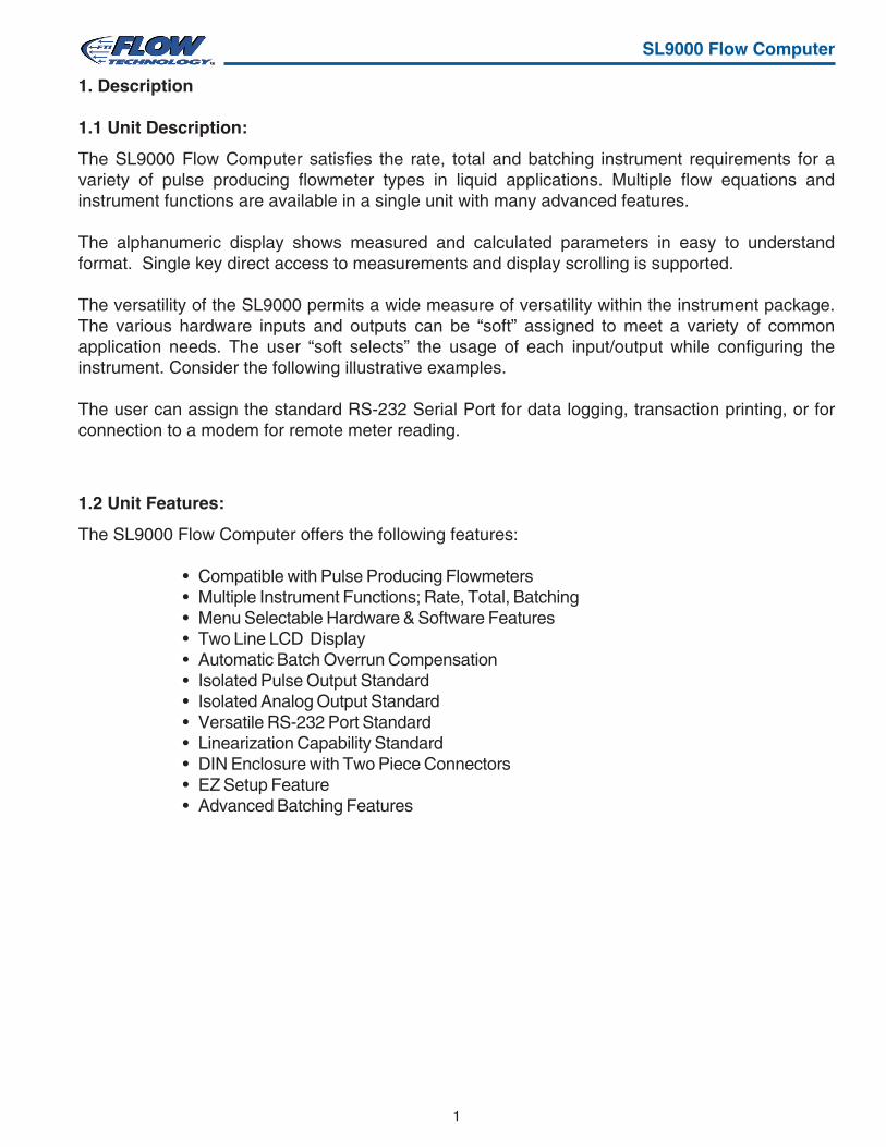
1. Description
1.1 Unit Description:
The SL9000 Flow Computer satisfies the rate, total and batching instrument requirements for avariety of pulse producing flowmeter types in liquid applications. Multiple flow equations andinstrument functions are available in a single unit with many advanced features.
The alphanumeric display shows measured and calculated parameters in easy to understandformat. Single key direct access to measurements and display scrolling is supported.
The versatility of the SL9000 permits a wide measure of versatility within the instrument package.The various hardware inputs and outputs can be “soft” assigned to meet a variety of commonapplication needs. The user “soft selects” the usage of each input/output while configuring theinstrument. Consider the following illustrative examples.
The user can assign the standard RS-232 Serial Port for data logging, transaction printing, or forconnection to a modem for remote meter reading.
1.2 Unit Features:
The SL9000 Flow Computer offers the following features:
• Compatible with Pulse Producing Flowmeters• Multiple Instrument Functions; Rate, Total, Batching• Menu Selectable Hardware & Software Features• Two Line LCD Display• Automatic Batch Overrun Compensation• Isolated Pulse Output Standard• Isolated Analog Output Standard• Versatile RS-232 Port Standard• Linearization Capability Standard• DIN Enclosure with Two Piece Connectors• EZ Setup Feature• Advanced Batching Features

2
SL9000 Flow Computer
1.3 Specifications:
Specifications:Environmental
Indoor UseAltitude up to 2000mOperating Temperature: 0°C to +50°C
(-20°C to 55°C optional)Storage Temperature: -40°C to +85 CMaximum Relative Humidity : 80% for temperatures
up to 31°C decreasing linearly to 50% RH at40°C
Main supply voltage fluctuations not to exceed±10% of the nominal voltageTransient overvoltage according to INSTALLATION
CATEGORY II (see UL 3101-1 Annex J)POLLUTION DEGREE 2 in accordance with
IEC 664 (see 3.7.3)Materials: UL, CSA, VDE approved
Approvals: CE Compliant Light Industrial,UL File #: E192404, C/UL
DisplayType: 2 lines of 20 charactersTypes: Backlit LCDCharacter Size: 0.3" nominalUser selectable label descriptors and units ofmeasure
KeypadKeypad Type: Membrane KeypadKeypad Rating: Sealed to Nema 4Number of keys: 16
EnclosureSize: See DimensionsDepth behind panel: 6.5" including matingconnectorType: DINMaterials: Plastic, UL94V-0, Flame retardantBezel: Textured per matt finishEquipment Labels: Model, safety, and user wiring
Power InputThe factory equipped power option is internally fused.An internal line to line filter capacitor is provided foradded transient suppression.Order Option 1: 110VAC: 85 to 127 Vrms, 50/60 HzOrder Option 2: 220VAC: 170 to 276 Vrms, 50/60HzOrder Option 3: 12VDC: 10.5 to 14 VDCOrder Option 4: 24VDC: 18 to 24 VDC
Flow Inputs:Pulse Inputs:
Number of Flow Inputs: oneConfigurations supported: single input with or
without quadrature (menu selectable)Input Impedance: 10 KΩ nominalPullup Resistance: 10 KΩ to 5 VDC (menu
selectable)Pull Down Resistance: 10 KΩ to commonTrigger Level: (menu selectable)
High Level InputLogic On: 3 to 30 VDCLogic Off: 0 to 1 VDCLow Level Input (mag pickup)
Selectable sensitivity: 10 mV & 100 mVMinimum Count Speed: User selectable down to1 pulse in 99 sec.Maximum Count Speed: Selectable: 0 to 20kHzOvervoltage Protection: 50 VDCFast Transient: Protected to 500 VDC
(Capacitive Clamp)
Control InputsSwitch Inputs are menu selectable for Start, Stop,Reset, Lock, Inhibit, Alarm Acknowledge, Print orNot Used.Control Input Specifications
Input Scan Rate: 10 scans per secondLogic 1: 4 - 30 VDCLogic 0: 0 - 0.8 VDCTransient Suppression: 500 V fast transient
(Capacitive Clamp)Input Impedance: 100 KΩControl Activation: Positive Edge or Pos. Levelbased on product definition
Excitation Voltage110/220 VAC Powered Units
Menu Selectable: 5, 12 or 24 VDC @ 100mA24 VDC Powered Units
Menu Selectable: 5 or 12 VDC @ 100mA12 VDC Powered Units
5 VDC @ 100mA
3
SL9000 Flow Computer
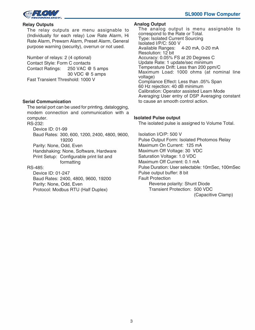
Relay OutputsThe relay outputs are menu assignable to(Individually for each relay) Low Rate Alarm, HiRate Alarm, Prewarn Alarm, Preset Alarm, Generalpurpose warning (security), overrun or not used.
Number of relays: 2 (4 optional)Contact Style: Form C contactsContact Ratings: 250 VAC @ 5 amps
30 VDC @ 5 ampsFast Transient Threshold: 1000 V
Serial CommunicationThe serial port can be used for printing, datalogging,modem connection and communication with acomputer.RS-232:
Device ID: 01-99Baud Rates: 300, 600, 1200, 2400, 4800, 9600,
19200Parity: None, Odd, EvenHandshaking: None, Software, HardwarePrint Setup: Configurable print list and
formattingRS-485:
Device ID: 01-247Baud Rates: 2400, 4800, 9600, 19200Parity: None, Odd, EvenProtocol: Modbus RTU (Half Duplex)
Analog OutputThe analog output is menu assignable tocorrespond to the Rate or Total.Type: Isolated Current SourcingIsolated I/P/C: 500 VAvailable Ranges: 4-20 mA, 0-20 mAResolution: 12 bitAccuracy: 0.05% FS at 20 Degrees CUpdate Rate: 1 update/sec minimumTemperature Drift: Less than 200 ppm/CMaximum Load: 1000 ohms (at nominal linevoltage)Compliance Effect: Less than .05% Span60 Hz rejection: 40 dB minimumCalibration: Operator assisted Learn ModeAveraging:User entry of DSP Averaging constantto cause an smooth control action.
Isolated Pulse outputThe isolated pulse is assigned to Volume Total.
Isolation I/O/P: 500 VPulse Output Form: Isolated Photomos RelayMaximum On Current: 125 mAMaximum Off Voltage: 30 VDCSaturation Voltage: 1.0 VDCMaximum Off Current: 0.1 mAPulse Duration: User selectable: 10mSec, 100mSecPulse output buffer: 8 bitFault Protection
Reverse polarity: Shunt DiodeTransient Protection: 500 VDC
(Capacitive Clamp)
4
SL9000 Flow Computer
Operating ModeThe Flow Computer can be thought of as making ameasurement of flow and then performingcalculations which are then updated periodicallyon the display as rate and total. The pulse output,analog output and the alarm relays are alsoupdated. The cycle then repeats itself.
Step 1:Update the measurements of input signals-Raw Input Measurements are made at each input.
Step 2 : Compute the Volumetric Flow-Uncompensated flow is the term given to the flowin volume units. The value is computed based onthe flowmeter input type selected and augmentedby any performance enhancing linearization thathas been specified by the user.
Step 3: Check Flow Alarms-The flow alarm functions have been assigned toflow rate during the setup of the instrument. Acomparison is now made by comparing the currentflow rates against the specified hi and low limits.
Step 4: Compute the Flow Totals by Summation-A flow total increment is computed for each flowrate. This increment is computed by dividing thepulses by the K-Factor and then summing. Thetotalizer format also includes provisions for totalrollover.
Step 5: Total Preset Comparisons-The total associated with a preset function is thencompared against the corresponding preset valueand any required control actions taken.
Step 6: Pulse Output Service-The pulse output is next updated by scaling thetotal increment which has just been determined bythe pulse output scaler and summing it to anyresidual pulse output amount.
Step 7: Compute the Analog Output-This designated flow rate value is now used tocompute the analog output.
Step 8: Update Display and Printer Output-The instrument finally runs a task to update thevarious table entries associated with the front paneldisplay and serial outputs.
Setup ModeThe setup mode is password protected by meansof a numeric lock out code established by the user.In addition, a secret, manufacturers numeric unlockentry sequence is available.
The system also provides a minimumimplementation of an “audit trail” which trackssignificant setup changes to the unit. This featureis increasingly being found of benefit to users orsimply required by Weights and MeasurementOfficials in systems used in commerce, trade, or“custody transfer” applications.
A Worksheet is provided to assist the user in settingup the instrument. An Easy Setup (EZ Setup)feature is offered in the setup menu. The EZSetup routine is a quick and easy way to configurethe unit for the most commonly used instrumentfunctions.
The setup mode has numerous subgrouping ofparameters needed for flow calculations. There isa well conceived hierarchy to the setup parameterlist. Selections made at the beginning of the setupaffect offerings further down in the lists.
In the setup mode, the flow computer activates thecorrect setup variables based on the instrumentconfiguration, the flow equation, and the hardwareselections, the flow transmitter type, and meterenhancements (linearization) options selected. Allrequired setup parameters are enabled. All setupparameters not required are suppressed.
A help line prompt is provided for each entry. Inaddition a help message is available which may beaccessed by depressing the “HELP” key.
Also note that in the setup mode are parameterselections which have preassigned industrystandard values. The unit will assume these valuesunless they are modified by the user.
5
SL9000 Flow Computer
Maintenance (Test) Mode:The Maintenance Mode of the SL9000 provides anumber of specialized utilities required forinstrument checkout on start-up, setupdocumentation and data logger access.
A password is required to gain access to thisspecialized mode of operation. Quality andmaintenance personnel will find this mode ofoperation very useful. It is also useful for factorytesting.
Many of these tests may be used during start-up ofa new system. Inputs signals may be read, andoutput signals may be exercised to verify theelectrical interconnects before the entire system isput on line.
The following action items may be performed inthe Maintenance Mode:
Print Setup ReportExamine Audit TrailExamine Error HistoryPerform Keypad CheckoutPerform Display CheckoutPerform Pulse Input CheckoutPerform Pulse Output CheckoutPerform Control Input CheckoutPerform Relay Output CheckoutPerform Analog Output CheckoutCalibrate Analog Output using the Learn FeaturePerform Excitation Output TestExamine or Dump Data Logger
RS-232 Serial PortThe SL9000 has a general purpose RS-232 Portwhich may be used for any one of the followingpurposes:
Transaction PrintingData LoggingRemote Metering by Modem (optional)Computer Communication LinkConfiguration by ComputerPrint System SetupPrint Malfunction History
Operation of Serial Communication Port withPrinters
SL9000's RS-232 channel supports a number ofoperating modes. One of these modes is intendedto support operation with a printer in meteringapplications requiring transaction printing, datalogging and/or printing of maintenance reports.
For transaction printing, the user defines the itemsto be included in the printed document. The usercan also select what initiates the transaction printgenerated as part of the setup of the instrument.The transaction document may be initiated via afront panel key depression, a remote contactclosure, upon completion of a batch, time of day orat a timed interval.
In data logging, the user defines the items to beincluded in each data log as a print list. The usercan also select when or how often he wishes adata log to be made. This is done during the setupof the instrument as either a time of day or as atime interval between logging.
The system setup and maintenance report lists allthe instrument setup parameters and usage for thecurrent instrument configuration. In addition, theAudit trail information is presented along with astatus report listing any observed malfunctionswhich have not been corrected.
The user initiates the printing of this report at adesignated point in the menu by pressing therequested key on the front panel.
Operation of Serial Port with Modems (optional)The SL9000 RS-232 channel supports a numberof operating modes. One of these modes isintended to support operation with a modem inremote metering applications.
An external modem is intentionally being used withthe SL9000. This permits use with the variety ofmodem standards worldwide while avoiding thespecialized approvals required for equipment thatis deemed to fall under the category oftelecommunication equipment.
In the modem mode, the SL9000 is assumed to beoperating in a remote metering role. In addition,the SL9000 will be capable of initiating a call to adesigned telephone number in the event of ametering malfunction.
6
SL9000 Flow Computer
SL9000 SL9000Bezel Adaptor
Gasket
Mounting Bracket
2. Installation
2.1 General Mounting Hints:
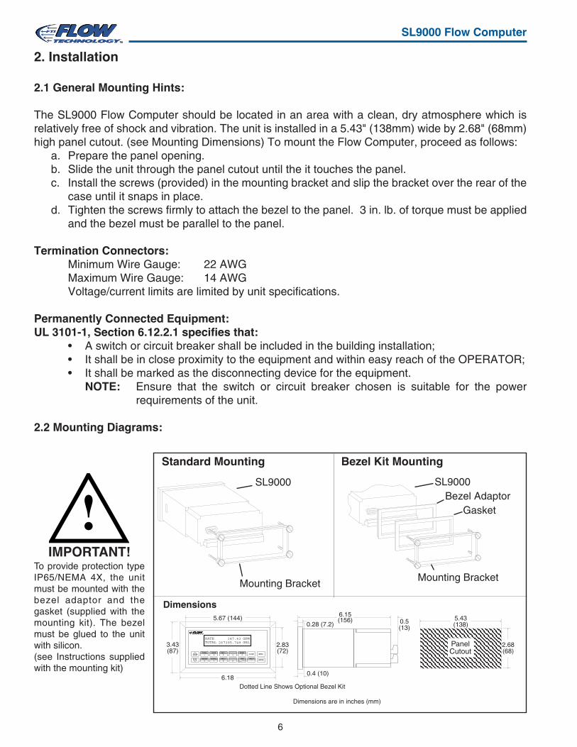
The SL9000 Flow Computer should be located in an area with a clean, dry atmosphere which isrelatively free of shock and vibration. The unit is installed in a 5.43" (138mm) wide by 2.68" (68mm)high panel cutout. (see Mounting Dimensions) To mount the Flow Computer, proceed as follows:
a. Prepare the panel opening.b. Slide the unit through the panel cutout until the it touches the panel.c. Install the screws (provided) in the mounting bracket and slip the bracket over the rear of the
case until it snaps in place.d. Tighten the screws firmly to attach the bezel to the panel. 3 in. lb. of torque must be applied
and the bezel must be parallel to the panel.
Termination Connectors:Minimum Wire Gauge: 22 AWGMaximum Wire Gauge: 14 AWGVoltage/current limits are limited by unit specifications.
Permanently Connected Equipment:UL 3101-1, Section 6.12.2.1 specifies that:
• A switch or circuit breaker shall be included in the building installation;• It shall be in close proximity to the equipment and within easy reach of the OPERATOR;• It shall be marked as the disconnecting device for the equipment.
NOTE: Ensure that the switch or circuit breaker chosen is suitable for the powerrequirements of the unit.
2.2 Mounting Diagrams:
Mounting Bracket
Standard Mounting Bezel Kit Mounting
Dimensions
Dotted Line Shows Optional Bezel Kit
PanelCutout
5.43(138)
2.68(68)
Dimensions are in inches (mm)
5.67 (144)
2.83(72)
3.43(87)
6.18
STOP
STARTPRINT
5
0 –
TIME
CLEAR
•
MENU
ENTERHELP
4PRE 1
3RATE
2TOTAL
1
GRAND6
SCROLL7
PRE 28 9
RATETOTAL 267395.749
GPMGAL
147.43
6.15(156) 0.5
(13)0.28 (7.2)
0.4 (10)
!IMPORTANT!
To provide protection typeIP65/NEMA 4X, the unitmust be mounted with thebezel adaptor and thegasket (supplied with themounting kit). The bezelmust be glued to the unitwith silicon.(see Instructions suppliedwith the mounting kit)
7
SL9000 Flow Computer
3. Applications
3.1 Liquid Volume
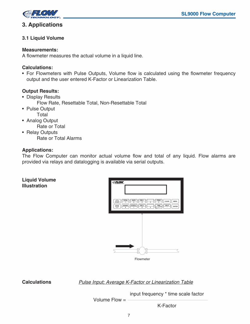
Measurements:A flowmeter measures the actual volume in a liquid line.
Calculations:• For Flowmeters with Pulse Outputs, Volume flow is calculated using the flowmeter frequency
output and the user entered K-Factor or Linearization Table.
Output Results:• Display Results
Flow Rate, Resettable Total, Non-Resettable Total• Pulse Output
Total• Analog Output
Rate or Total• Relay Outputs
Rate or Total Alarms
Applications:The Flow Computer can monitor actual volume flow and total of any liquid. Flow alarms areprovided via relays and datalogging is available via serial outputs.
Pulse Input; Average K-Factor or Linearization Table
input frequency * time scale factorVolume Flow =
K-Factor
Liquid VolumeIllustration
Calculations
Flowmeter
STOP
START 5
0 –
PRINTCLEAR
•
MENU
ENTERHELP
4PRE 1
3RATE
2TOTAL
1
GRAND6
SCROLL7
PRE 28 9
TIME

8
SL9000 Flow Computer
3.2 Batching
Measurements:A flowmeter measures the actual volume in a liquid line.
Calculations:• For Flowmeters with Pulse Outputs, Volume flow is calculated using the flowmeter frequency
output and the user entered K-Factor or Linearization Table.
Output Results:• Display Results
Flow Rate, Batch Total, Non-Resettable Total• Pulse Output
Total• Analog Output
Rate or Total• Relay Outputs
Batch Total, Rate, or Alarms
Applications:Batching and monitoring flow and total of any liquid. Batching is accomplished via relays anddatalogging is available via serial outputs.
Batching Illustration
Calculations
STOP
START 5
0 –
PRINTCLEAR
•
MENU
ENTERHELP
4PRE 1
3RATE
2TOTAL
1
GRAND6
SCROLL7
PRE 28 9
TIME
Flowmeter Solenoid Valve
Pulse Input; Average K-Factor or Linearization Table
input frequency * time scale factorVolume Flow =
K-Factor
9
SL9000 Flow Computer
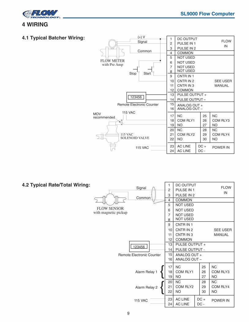
4 WIRING
4.1 Typical Batcher Wiring:
4.2 Typical Rate/Total Wiring:
FLOW SENSORwith magnetic pickup
115 VAC
Signal
Common
123456
Remote Electronic Counter
Alarm Relay 1
Alarm Relay 2
13 PULSE OUTPUT +PULSE OUTPUT -
ANALOG OUT –ANALOG OUT +
RLY1
RLY2
AC LINEAC LINE24
18 COM19202122
23
NONCCOMNO
141516
17 NC
POWER INDC -
COM RLY3
COM RLY4
2627282930
NONC
NO
DC +
25 NC
PULSE IN 1PULSE IN 2
DC OUTPUT
COMMON
NOT USEDNOT USEDNOT USED
CNTR IN 1CNTR IN 2CNTR IN 3COMMON
NOT USED
89101112
234567
1
SEE USERMANUAL
INFLOW
FLOW METERwith Pre Amp
115 VACSOLENOID VALVE
MOVrecommended
115 VAC
115 VAC
(+) VSignal
Common
StartStop
123456
Remote Electronic Counter
13 PULSE OUTPUT +PULSE OUTPUT –
ANALOG OUT –ANALOG OUT +
RLY1
RLY2
AC LINEAC LINE24
18 COM19202122
23
NONCCOMNO
141516
17 NC
POWER INDC -
COM RLY3
COM RLY4
2627282930
NONC
NO
DC +
25 NC
PULSE IN 1PULSE IN 2
DC OUTPUT
COMMON
NOT USEDNOT USEDNOT USED
CNTR IN 1CNTR IN 2CNTR IN 3COMMON
NOT USED
89101112
234567
1
SEE USERMANUAL
INFLOW
10
SL9000 Flow Computer
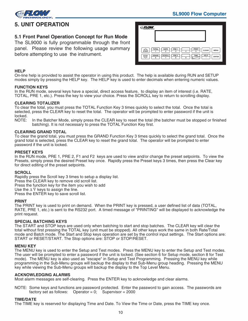
5. UNIT OPERATION
5.1 Front Panel Operation Concept for Run ModeThe SL9000 is fully programmable through the frontpanel. Please review the following usage summarybefore attempting to use the instrument.
HELPOn-line help is provided to assist the operator in using this product. The help is available during RUN and SETUPmodes simply by pressing the HELP key. The HELP key is used to enter decimals when entering numeric values.
FUNCTION KEYSIn the RUN mode, several keys have a special, direct access feature, to display an item of interest (i.e. RATE,TOTAL, PRE 1, etc.). Press the key to view your choice. Press the SCROLL key to return to scrolling display.
CLEARING TOTALIZERTo clear the total, you must press the TOTAL Function Key 3 times quickly to select the total. Once the total isselected, press the CLEAR key to reset the total. The operator will be prompted to enter password if the unit islocked.NOTE: In the Batcher Mode, simply press the CLEAR key to reset the total (the batcher must be stopped or finished
batching). It is not necessary to press the TOTAL Function Key first.
CLEARING GRAND TOTALTo clear the grand total, you must press the GRAND Function Key 3 times quickly to select the grand total. Once thegrand total is selected, press the CLEAR key to reset the grand total. The operator will be prompted to enterpassword if the unit is locked.
PRESET KEYSIn the RUN mode, PRE 1, PRE 2, F1 and F2 keys are used to view and/or change the preset setpoints. To view thePresets, simply press the desired Preset key once. Rapidly press the Preset keys 3 times, then press the Clear keyfor direct editing of the preset setpoints.
SCROLLRapidly press the Scroll key 3 times to setup a display list.Press the CLEAR key to remove old scroll list.Press the function key for the item you wish to addUse the ∆ ∇ keys to assign the line.Press the ENTER key to save scroll list.
PRINTThe PRINT key is used to print on demand. When the PRINT key is pressed, a user defined list of data (TOTAL,RATE, PRE 1, etc.) is sent to the RS232 port. A timed message of "PRINTING" will be displayed to acknowledge theprint request.
SPECIAL BATCHING KEYSThe START and STOP keys are used only when batching to start and stop batches. The CLEAR key will clear thetotal without first pressing the TOTAL key (unit must be stopped). All other keys work the same in both Rate/Totalmode and Batch mode. The Start and Stop keys operation are set by the control input settings. The Start options are:START or RESET/START. The Stop options are: STOP or STOP/RESET.
MENU KEYThe MENU key is used to enter the Setup and Test modes. Press the MENU key to enter the Setup and Test modes.The user will be prompted to enter a password if the unit is locked. (See section 6 for Setup mode, section 8 for Testmode). The MENU key is also used as "escape" in Setup and Test Programming. Pressing the MENU key whileprogramming in the Sub-Menu groups will backup the display to that Sub-Menu group heading. Pressing the MENUkey while viewing the Sub-Menu groups will backup the display to the Top Level Menu.
ACKNOWLEDGING ALARMSMost alarm messages are self-clearing. Press the ENTER key to acknowledge and clear alarms.
NOTE: Some keys and functions are password protected. Enter the password to gain access. The passwords arefactory set as follows: Operator = 0; Supervisor = 2000
TIME/DATEThe TIME key is reserved for displaying Time and Date. To View the Time or Date, press the TIME key once.
STOP
START 5
0 –
PRINTCLEAR
•
MENU
ENTERHELP
4PRE 1
3RATE
2TOTAL
1
GRAND6
SCROLL7
PRE 28 9
TIME
11
SL9000 Flow Computer
5.2 General Operation
The unit can display: Rate, Total, Grand Total, Presets and Time of Day. The unit can be programmed toperform Ratemeter/Totalizer or Batching functions.
5.3 Ratemeter/Totalizer Operation
The Ratemeter/Totalizer mode is used primarily to monitor flowrate and accumulated total. The relays canbe used to trigger on flow rate, total, or alarms.
5.3.1 Password Protection for Rate/Total mode
After an Operator and/or Supervisor Password is entered in the setup mode (see section 6.3, SETUPPASSWORD submenu), the unit will be locked. The unit will prompt the user for the password when trying toperform the following functions:
Clear TotalClear Grand TotalEnter MenuEdit Preset 1 (PRE 1 Key)Edit Preset 2 (PRE 2 Key)Edit Preset 3 (4 Key)Edit Preset 4 (9 Key)
The Supervisor password should be reserved for supervisors. The Supervisor password will allow access torestricted areas of the Setup and Test menus.
5.3.2 Relay Operation in Rate/Total mode
Up to four relays are available (two standard) for alarm outputs. The relays can be assigned to trip accordingto rate, total or general system alarms. The relays can be programmed for low or high alarms.Preset 1 (RLY1) and Preset 2 (RLY2) are easily accessible by pressing the PRE 1 or PRE 2 key on the frontpanel. Preset 3 and Preset 4 are accessible by pressing the 4 or 9 keys.
5.3.3 Pulse Output in Rate/Total mode
The isolated pulse output (open collector) is assigned to Volume Total. The pulse output duration can beset for 10mS (50 Hz max) or 100mS (5 Hz max). A pulse output scale factor (pulse value) can be set to scalethe pulse output. The pulse output is ideal for connecting to remote totalizers or other devices such as aPLC. See section 1.3 for electrical specifications.
5.3.4 Analog Output in Rate/Total mode
The analog output is menu assignable to correspond to the Volume Rate or Volume Total. The analogoutput is ideal for "trend" tracking using strip chart recorders or other devices.

12
SL9000 Flow Computer
5.3.5 RS-232 Serial Port Operation in Rate/Total mode
The RS-232 serial port can be used for programming (using the Setup Disk) or for communicating toprinters and computers in the Operating Mode (Run Mode).
PC Communications:The Setup Disk also allows the user to query the unit for operating status such as Flow Rate, Flow Total,Presets, etc.
Operation of RS-232 Serial Port with Printers:Transaction PrintingFor transaction printing, the user defines the items to be included in the printed document (see section6.3.20 SET DATA OUTPUT, Select_list). The transaction document can be initiated by pressing thePRINT key or by a remote contact closure.
Data LoggingIn data logging, the user defines the items to be included in each data log (see section 6.3.20 SETPRINTER OUTPUT, Select_list). The user can also select when (time of day) or how often (print interval)the data log is to be made (see section 6.3.19 SET PRINTER OUTPUT, Configure).
System Setup and Maintenance ReportThe system setup and maintenance report lists all of the instrument setup parameters and usage for thecurrent instrument configuration. The audit trail information and a status report is also printed. This reportis initiated in the Test menu (see section 8.2.3 PRINT SYSTEM SETUP).
5.3.6 RS-485 Serial Port (optional)
RS-485 Port Description:
The optional RS-485 card utilizes Modbus RTU protocol to access a variety of processparameters and totalizers. The Relays can be controlled via Modbus. In addition, actionroutines can be executed. For further information, contact factory and request RS-485Protocol manual.
Operation of Serial Communication Port with PC
The flow computer's RS-485 channel supports a number of Modbus RTU commands. ModbusRTU drivers are available from third party sources for a variety of Man Machine Interfacesoftware for IBM compatible PC's.
The user reads and writes information from/to the RS-485 using the Modbus RTU commands.The SL9000 then responds to these information and command requests.
Process variables and totalizers are read in register pairs in floating point format. Time anddate are read as a series of integer register values. Alarms are individually read as coils.Action routines are initiated by writing to coils.
13
SL9000 Flow Computer
5.4 Batcher OperationThe Batcher mode is used primarily to control batches. The main difference between the Batch mode andRate/Total mode is the relay operation. The Batch mode allows the operator to "START" the unit via thefront panel or remote input. Once started, the relays (RLY1 & RLY2) will energize and send a contact to aflow control device (i.e. solenoid valve or pump). The flow sensor will send a signal to the unit and totalaccumulation will begin. Just before the end of batch, when the Prewarn value (PRE 2) is reached, Relay 2will drop out (this is ideal for flow slow down). When the final Batch amount (PRE 1) is reached, Relay 1 willdrop out and the Batch is complete.
Several messages will be displayed during normal batch operation (i.e. Batch Fill, Batch Stopped). Thekeypad is disabled for the duration of these timed messages (approx. 2 sec).
5.4.1 Batcher Configuration.When the unit is programmed for batch mode, several batch operation choices are available. These choicesinclude: EZ Preset, Up or Down Counting, Maximum Batch Preset, Batch Overrun Compensation, AutoBatch Restart, Time Delay, Flow Signal Timeout, Maximum Drain Time, Slow Start Quantity, Start or Reset/Start, and Stop or Stop/Reset.
EZ PresetA selectable mode of batching where user can press "PRE 1", then "ENTER" then the quantity to bebatched, then "START" for a quick enter-start sequence.
Batch Count ModeThe Batch Count Mode allows the user to choose whether the unit will batch up to a preset value or batchdown from a preset value to zero.
Maximum Batch PresetThe Maximum Batch Preset allows the user to program the Maximum Batch value allowed to be entered bythe operator. If an operator should try to program a batch higher then this value, the unit will not allow thevalue to be entered and will prompt the user with an error message saying that the permitted MaximumBatch Preset size has been exceeded.
Batch OverrunThe Batch Overrun is used for batch applications that have slow responding valves and a consistentbatching flowrate. When the Batch Overrun is set, the unit will compensate for batch overruns by computingan averaged overrun value from the last four batches. This average is used to internally adjust the batchsetpoint to minimize overrun. The maximum drain time must be set greater than the slowest valve responsetime for proper operation of this feature.
Auto Batch RestartThe Auto Batch Restart function allows the user to set an amount of time to automatically restart a batchafter the completion of a batch. This time can be set from 1 to 99 seconds.
Flow Signal TimeoutThe Flow Signal Timeout allows the user to enter a timeout of 0 to 99 seconds. If a batch is “Filling” and zeroflow persists for more than the user entered time then the batch will be aborted. This prevents over flows dueto faulty flow sensors and/or wiring.
Maximum Drain TimeThe unit declares that a batch is “done” when the flow rate equals “0”. A flow rate may be present long afterthe Preset Relay de-energizes due to slow reacting valves or leaky valves. The Maximum Drain Time allowsthe user to enter an amount of time (0 to 99 seconds) to wait before declaring “Batch Done”. After the PresetBatch quantity is reached, the unit will declare “Batch Done” when the flow rate is “0” or the Maximum DrainTime has expired. The batch data will then be available for printing and datalogging.
Slow Start QuantityThe Slow Start Quantity is a function that allows an amount to be entered for a Slow Start of fill. This functionrequires two stage valve control. RLY 1 (slow flow) will energize for Slow Start and RLY 2 (fast flow) willenergize after the Slow Start Quantity has been delivered. This helps reduce turbulence when filling anempty container.
14
SL9000 Flow Computer
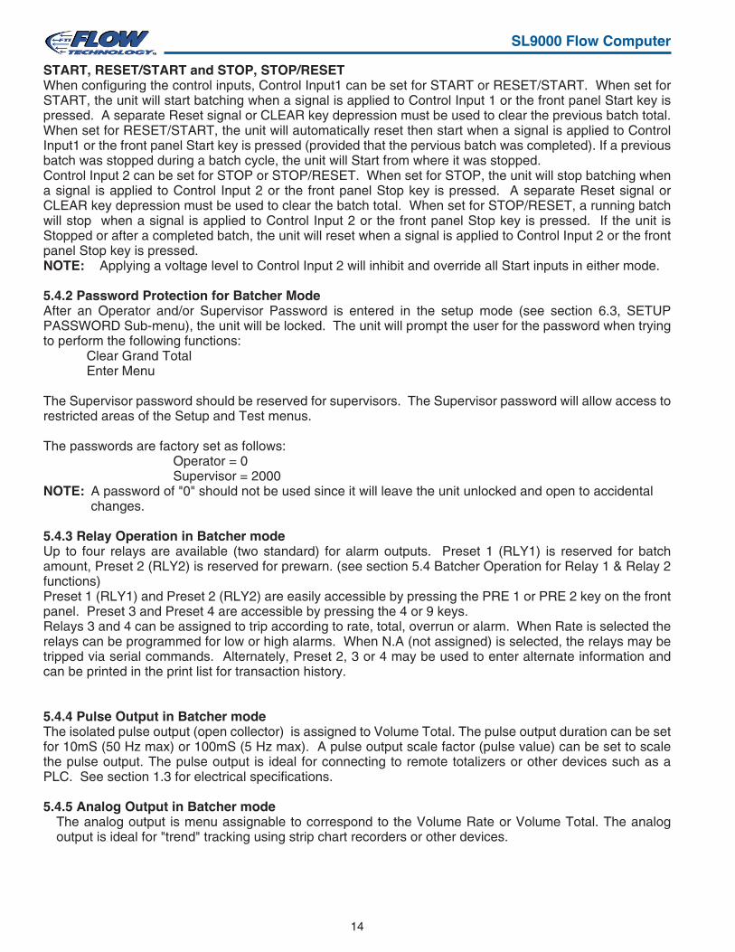
START, RESET/START and STOP, STOP/RESETWhen configuring the control inputs, Control Input1 can be set for START or RESET/START. When set forSTART, the unit will start batching when a signal is applied to Control Input 1 or the front panel Start key ispressed. A separate Reset signal or CLEAR key depression must be used to clear the previous batch total.When set for RESET/START, the unit will automatically reset then start when a signal is applied to ControlInput1 or the front panel Start key is pressed (provided that the pervious batch was completed). If a previousbatch was stopped during a batch cycle, the unit will Start from where it was stopped.Control Input 2 can be set for STOP or STOP/RESET. When set for STOP, the unit will stop batching whena signal is applied to Control Input 2 or the front panel Stop key is pressed. A separate Reset signal orCLEAR key depression must be used to clear the batch total. When set for STOP/RESET, a running batchwill stop when a signal is applied to Control Input 2 or the front panel Stop key is pressed. If the unit isStopped or after a completed batch, the unit will reset when a signal is applied to Control Input 2 or the frontpanel Stop key is pressed.NOTE: Applying a voltage level to Control Input 2 will inhibit and override all Start inputs in either mode.
5.4.2 Password Protection for Batcher ModeAfter an Operator and/or Supervisor Password is entered in the setup mode (see section 6.3, SETUPPASSWORD Sub-menu), the unit will be locked. The unit will prompt the user for the password when tryingto perform the following functions:
Clear Grand TotalEnter Menu
The Supervisor password should be reserved for supervisors. The Supervisor password will allow access torestricted areas of the Setup and Test menus.
The passwords are factory set as follows:Operator = 0Supervisor = 2000
NOTE: A password of "0" should not be used since it will leave the unit unlocked and open to accidentalchanges.
5.4.3 Relay Operation in Batcher modeUp to four relays are available (two standard) for alarm outputs. Preset 1 (RLY1) is reserved for batchamount, Preset 2 (RLY2) is reserved for prewarn. (see section 5.4 Batcher Operation for Relay 1 & Relay 2functions)Preset 1 (RLY1) and Preset 2 (RLY2) are easily accessible by pressing the PRE 1 or PRE 2 key on the frontpanel. Preset 3 and Preset 4 are accessible by pressing the 4 or 9 keys.Relays 3 and 4 can be assigned to trip according to rate, total, overrun or alarm. When Rate is selected therelays can be programmed for low or high alarms. When N.A (not assigned) is selected, the relays may betripped via serial commands. Alternately, Preset 2, 3 or 4 may be used to enter alternate information andcan be printed in the print list for transaction history.
5.4.4 Pulse Output in Batcher modeThe isolated pulse output (open collector) is assigned to Volume Total. The pulse output duration can be setfor 10mS (50 Hz max) or 100mS (5 Hz max). A pulse output scale factor (pulse value) can be set to scalethe pulse output. The pulse output is ideal for connecting to remote totalizers or other devices such as aPLC. See section 1.3 for electrical specifications.
5.4.5 Analog Output in Batcher modeThe analog output is menu assignable to correspond to the Volume Rate or Volume Total. The analogoutput is ideal for "trend" tracking using strip chart recorders or other devices.
15
SL9000 Flow Computer
5.4.6 RS-232 Serial Port Operation in Batcher modeThe RS-232 serial port can be used for programming (using the Setup Disk) or for communicating to printersand computers in the Operating Mode (Run Mode).
PC Communications:The Setup Disk also allows the user to query the unit for operating status such as Flow Rate, Flow Total,Presets, etc.
Operation of RS-232 Serial Port with Printers:Transaction PrintingFor transaction printing, the user defines the items to be included in the printed document (see section6.3.20 SET DATA OUTPUT, Select_list). The transaction document can be initiated by pressing the PRINTkey, by a remote contact closure or print at end of batch.
Data LoggingIn data logging, the user defines the items to be included in each data log (see section 6.3.20 SET PRINTEROUTPUT, Select_list). The user can also select when (time of day) or how often (print interval) the data logis to be made (see section 6.3.19 SET PRINTER OUTPUT, Configure).
System Setup and Maintenance ReportThe system setup and maintenance report lists all of the instrument setup parameters and usage for thecurrent instrument configuration. The audit trail information and a status report is also printed. This report isinitiated in the Test menu (see section 8.2.3 PRINT SYSTEM SETUP).
5.4.7 RS-485 Serial Port (optional)
RS-485 Port Description:
The optional RS-485 card utilizes Modbus RTU protocol to access a variety of process parameters andtotalizers. Batches/Relays can be controlled remotely via Modbus. In addition, action routines can beexecuted. For further information, contact factory and request RS-485 Protocol manual.
Operation of Serial Communication Port with PC
The flow computer's RS-485 channel supports a number of Modbus RTU commands. Modbus RTU driversare available from third party sources for a variety of Man Machine Interface software for IBM compatiblePC's.
The user reads and writes information from/to the RS-485 using the Modbus RTU commands. The SL9000then responds to these information and command requests.
Process variables and totalizers are read in register pairs in floating point format. Time and date are read asa series of integer register values. Alarms are individually read as coils. Action routines are initiated bywriting to coils.
16
SL9000 Flow Computer
STOP
START 5
0 –
PRINTCLEAR
•
MENU
ENTERHELP
4PRE 1
3RATE
2TOTAL
1
GRAND6
SCROLL7
PRE 28 9
TIME
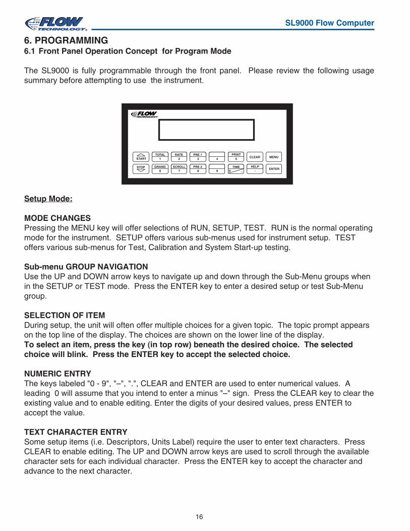
6. PROGRAMMING6.1 Front Panel Operation Concept for Program Mode
The SL9000 is fully programmable through the front panel. Please review the following usagesummary before attempting to use the instrument.
Setup Mode:
MODE CHANGESPressing the MENU key will offer selections of RUN, SETUP, TEST. RUN is the normal operatingmode for the instrument. SETUP offers various sub-menus used for instrument setup. TESToffers various sub-menus for Test, Calibration and System Start-up testing.
Sub-menu GROUP NAVIGATIONUse the UP and DOWN arrow keys to navigate up and down through the Sub-Menu groups whenin the SETUP or TEST mode. Press the ENTER key to enter a desired setup or test Sub-Menugroup.
SELECTION OF ITEMDuring setup, the unit will often offer multiple choices for a given topic. The topic prompt appearson the top line of the display. The choices are shown on the lower line of the display.To select an item, press the key (in top row) beneath the desired choice. The selectedchoice will blink. Press the ENTER key to accept the selected choice.
NUMERIC ENTRYThe keys labeled "0 - 9", "–", ".", CLEAR and ENTER are used to enter numerical values. Aleading 0 will assume that you intend to enter a minus "–" sign. Press the CLEAR key to clear theexisting value and to enable editing. Enter the digits of your desired values, press ENTER toaccept the value.
TEXT CHARACTER ENTRYSome setup items (i.e. Descriptors, Units Label) require the user to enter text characters. PressCLEAR to enable editing. The UP and DOWN arrow keys are used to scroll through the availablecharacter sets for each individual character. Press the ENTER key to accept the character andadvance to the next character.
17
SL9000 Flow Computer
SELECT OPERATE STATERun Setup Test
SELECT EZ SETUP
CHANGES ALL SETUPS !No Yes
INSTRUMENT TYPERate/Tot Batch
RATE TIME BASESec Min Hour Day
RATE DEC PLACES(0-4)0
TOTAL VOLUME UNITSgal
TOT DEC PLACES (0-3)0
K_FACTOR TYPEAvg LinTbl
AVERAGE KA-FACTOR ####### P/gal
LINEAR TABLE KAFre01:######## Hz
LINEAR TABLE KAKA--01:##########
FS ANALOG OUT 20mA #######gal/m
RATE 00.0 gal/mTOTAL 0 gal
ENTER
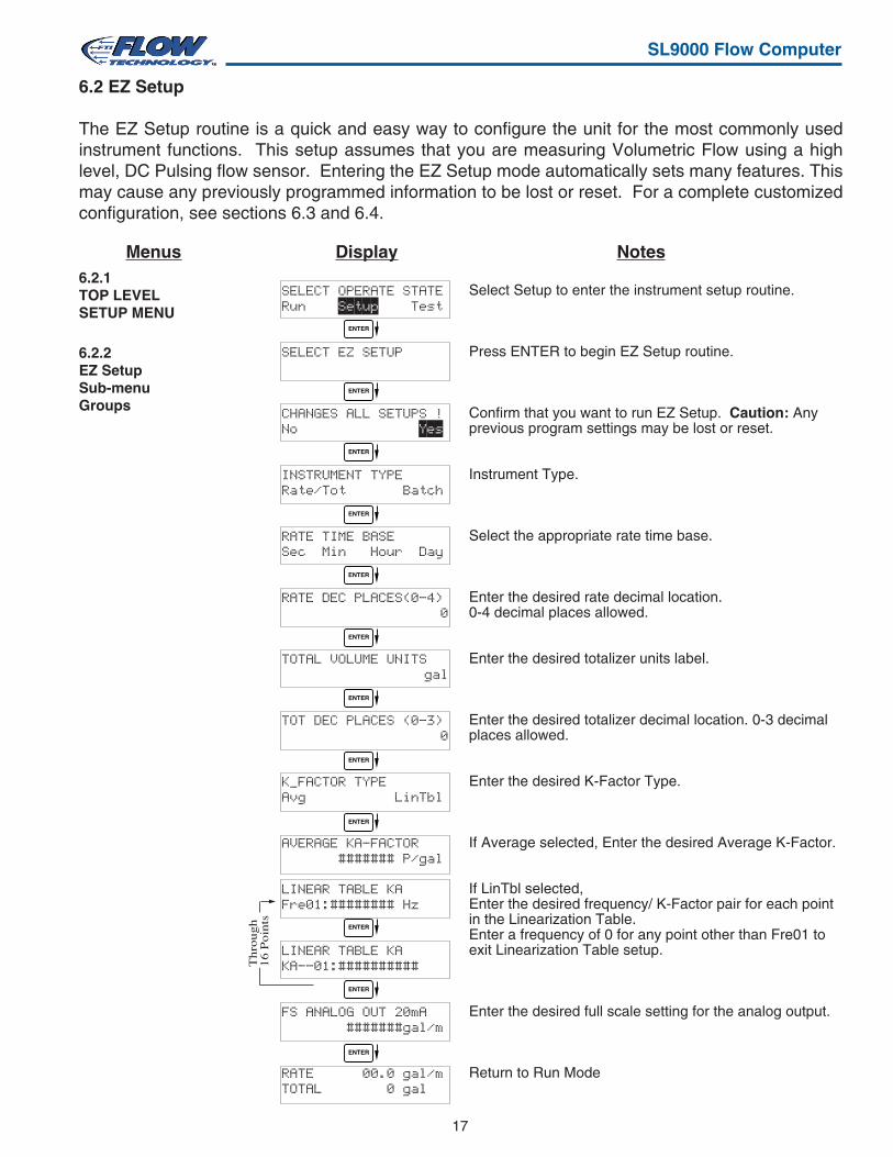
6.2.1TOP LEVELSETUP MENU
Menus Display Notes
Select Setup to enter the instrument setup routine.
Press ENTER to begin EZ Setup routine.
Confirm that you want to run EZ Setup. Caution: Anyprevious program settings may be lost or reset.
Instrument Type.
Select the appropriate rate time base.
Enter the desired rate decimal location.0-4 decimal places allowed.
Enter the desired totalizer units label.
Enter the desired totalizer decimal location. 0-3 decimalplaces allowed.
Enter the desired K-Factor Type.
If Average selected, Enter the desired Average K-Factor.
If LinTbl selected,Enter the desired frequency/ K-Factor pair for each pointin the Linearization Table.Enter a frequency of 0 for any point other than Fre01 toexit Linearization Table setup.
Enter the desired full scale setting for the analog output.
Return to Run Mode
6.2.2EZ SetupSub-menuGroups
6.2 EZ Setup
The EZ Setup routine is a quick and easy way to configure the unit for the most commonly usedinstrument functions. This setup assumes that you are measuring Volumetric Flow using a highlevel, DC Pulsing flow sensor. Entering the EZ Setup mode automatically sets many features. Thismay cause any previously programmed information to be lost or reset. For a complete customizedconfiguration, see sections 6.3 and 6.4.
ENTER
ENTER
ENTER
ENTER
ENTER
ENTER
ENTER
ENTER
ENTER
ENTER
ENTER
Th
rou
gh
16
Po
ints
18
SL9000 Flow Computer
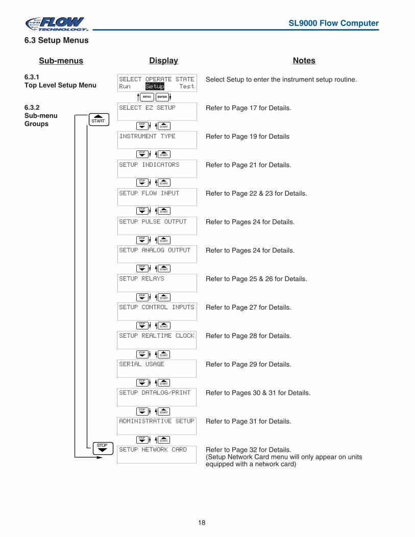
6.3.1Top Level Setup Menu
6.3.2Sub-menuGroups
SELECT OPERATE STATERun Setup Test
SELECT EZ SETUP
INSTRUMENT TYPE
SETUP INDICATORS
SETUP FLOW INPUT
SETUP PULSE OUTPUT
SETUP ANALOG OUTPUT
SETUP RELAYS
SETUP CONTROL INPUTS
SETUP REALTIME CLOCK
SERIAL USAGE
SETUP DATALOG/PRINT
ADMINISTRATIVE SETUP
SETUP NETWORK CARD
Select Setup to enter the instrument setup routine.
Refer to Page 17 for Details.
Refer to Page 19 for Details
Refer to Page 21 for Details.
Refer to Page 22 & 23 for Details.
Refer to Pages 24 for Details.
Refer to Pages 24 for Details.
Refer to Page 25 & 26 for Details.
Refer to Page 27 for Details.
Refer to Page 28 for Details.
Refer to Page 29 for Details.
Refer to Pages 30 & 31 for Details.
Refer to Page 31 for Details.
Refer to Page 32 for Details.(Setup Network Card menu will only appear on unitsequipped with a network card)
STARTSTART
STOP
STOP
6.3 Setup Menus
Display Notes
ENTERMENU
STARTSTOP
STARTSTOP
STARTSTOP
STARTSTOP
STARTSTOP
STARTSTOP
STARTSTOP
STARTSTOP
STARTSTOP
STARTSTOP
STARTSTOP
Sub-menus
19
SL9000 Flow Computer
NotesDisplaySub-menusSELECT EZ SETUP
Advance ToINSTRUMENT TYPE
INSTRUMENT TYPE
INSTRUMENT TYPERate/Tot Batch
Advance ToSELECT FLOW EQUATION
INSTRUMENT TYPE
INSTRUMENT TYPERate/Tot Batch
SELECT PRESET TYPEStandard EZ-Preset
BATCH COUNT MODEUp Down
Continue On Next Page
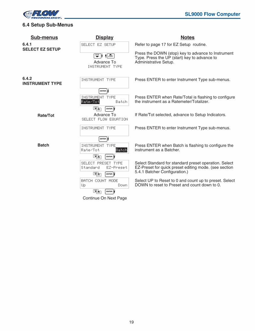
6.4.2INSTRUMENT TYPE
6.4.1SELECT EZ SETUP
Rate/Tot
Batch
6.4 Setup Sub-Menus
STARTSTOP
ENTER
STOP
STARTENTER
ENTER
STOP
STARTENTER
STOP
STARTENTER
STOP
STARTENTER
Refer to page 17 for EZ Setup routine.
Press the DOWN (stop) key to advance to InstrumentType. Press the UP (start) key to advance toAdministrative Setup.
Press ENTER to enter Instrument Type sub-menus.
Press ENTER when Rate/Total is flashing to configurethe instrument as a Ratemeter/Totalizer.
If Rate/Tot selected, advance to Setup Indicators.
Press ENTER to enter Instrument Type sub-menus.
Press ENTER when Batch is flashing to configure theinstrument as a Batcher.
Select Standard for standard preset operation. SelectEZ-Preset for quick preset editing mode. (see section5.4.1 Batcher Configuration.)
Select UP to Reset to 0 and count up to preset. SelectDOWN to reset to Preset and count down to 0.
20
SL9000 Flow Computer
NotesSub-menus
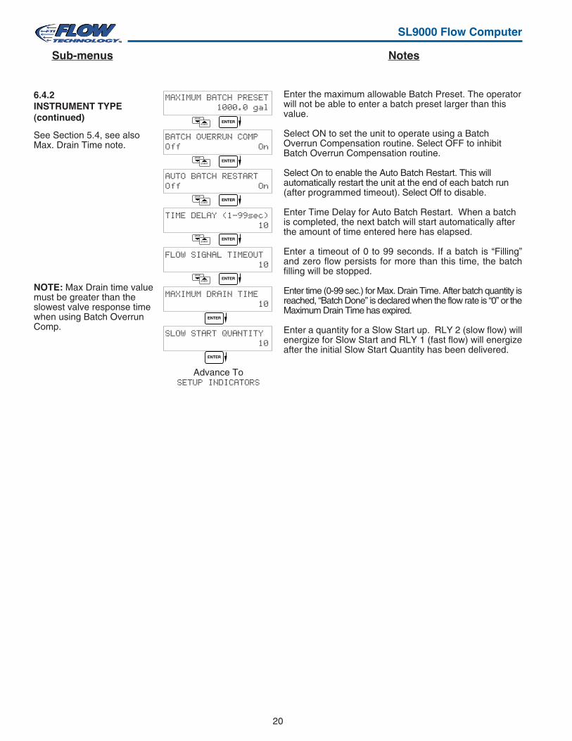
6.4.2INSTRUMENT TYPE(continued)
MAXIMUM BATCH PRESET 1000.0 gal
BATCH OVERRUN COMPOff On
AUTO BATCH RESTARTOff On
TIME DELAY (1-99sec) 10
FLOW SIGNAL TIMEOUT 10
MAXIMUM DRAIN TIME 10
SLOW START QUANTITY 10
Advance ToSETUP INDICATORS
STOP
STARTENTER
STOP
STARTENTER
STOP
STARTENTER
STOP
STARTENTER
STOP
STARTENTER
ENTER
ENTER
Enter the maximum allowable Batch Preset. The operatorwill not be able to enter a batch preset larger than thisvalue.
Select ON to set the unit to operate using a BatchOverrun Compensation routine. Select OFF to inhibitBatch Overrun Compensation routine.
Select On to enable the Auto Batch Restart. This willautomatically restart the unit at the end of each batch run(after programmed timeout). Select Off to disable.
Enter Time Delay for Auto Batch Restart. When a batchis completed, the next batch will start automatically afterthe amount of time entered here has elapsed.
Enter a timeout of 0 to 99 seconds. If a batch is “Filling”and zero flow persists for more than this time, the batchfilling will be stopped.
Enter time (0-99 sec.) for Max. Drain Time. After batch quantity isreached, “Batch Done” is declared when the flow rate is “0” or theMaximum Drain Time has expired.
Enter a quantity for a Slow Start up. RLY 2 (slow flow) willenergize for Slow Start and RLY 1 (fast flow) will energizeafter the initial Slow Start Quantity has been delivered.
See Section 5.4, see alsoMax. Drain Time note.
NOTE: Max Drain time valuemust be greater than theslowest valve response timewhen using Batch OverrunComp.
21
SL9000 Flow Computer
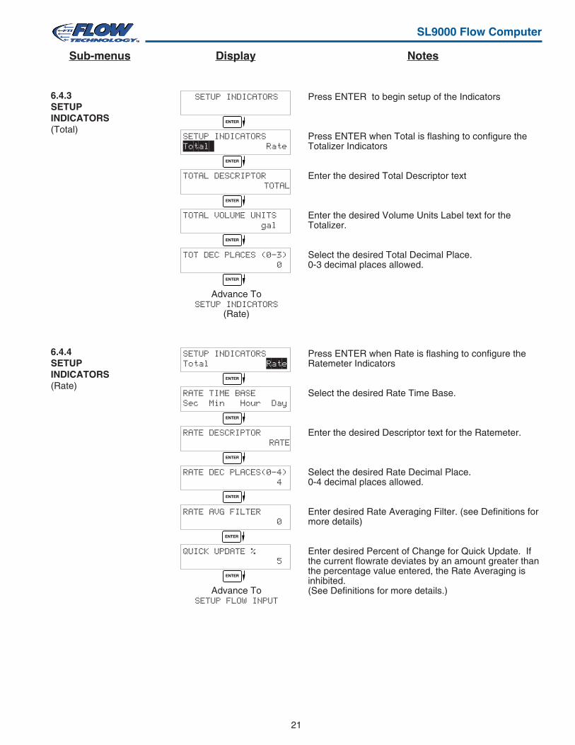
Press ENTER to begin setup of the Indicators
Press ENTER when Total is flashing to configure theTotalizer Indicators
Enter the desired Total Descriptor text
Enter the desired Volume Units Label text for theTotalizer.
Select the desired Total Decimal Place.0-3 decimal places allowed.
Press ENTER when Rate is flashing to configure theRatemeter Indicators
Select the desired Rate Time Base.
Enter the desired Descriptor text for the Ratemeter.
Select the desired Rate Decimal Place.0-4 decimal places allowed.
Enter desired Rate Averaging Filter. (see Definitions formore details)
Enter desired Percent of Change for Quick Update. Ifthe current flowrate deviates by an amount greater thanthe percentage value entered, the Rate Averaging isinhibited.(See Definitions for more details.)
SETUP INDICATORS
SETUP INDICATORSTotal Rate
TOTAL DESCRIPTOR TOTAL
TOTAL VOLUME UNITS gal
TOT DEC PLACES (0-3) 0
Advance ToSETUP INDICATORS
(Rate)
SETUP INDICATORSTotal Rate
RATE TIME BASESec Min Hour Day
RATE DESCRIPTORRATE
RATE DEC PLACES(0-4) 4
RATE AVG FILTER 0
QUICK UPDATE % 5
Advance ToSETUP FLOW INPUT
6.4.3SETUPINDICATORS(Total)
6.4.4SETUPINDICATORS(Rate)
NotesDisplaySub-menus
ENTER
ENTER
ENTER
ENTER
ENTER
ENTER
ENTER
ENTER
ENTER
ENTER
ENTER
22
SL9000 Flow Computer
SETUP FLOW INPUT
EXCITATION VOLTAGE5v 12v 24v
PULSE INPUT TYPEchA chA=chB Qx1 Qx2
PULSE TRIGGER LEVEL10mV 100mV 2.5V
LOW PASS FILTER40Hz 3KHz 20KHz
INPUT TERMINATIONPullup Pulldown None
MAX WINDOW (1-99)1
K_FACTOR TYPEAvg LinTbl
AVERAGE KA-FACTOR####### P/gal
LINEAR TABLE KAFre01:######## Hz
LINEAR TABLE KAKA--01:####### P/gal
LOW FLOW RATE ALARM ####### gal/m
HIGH FLOW RATE ALARM####### gal/m
Advance ToSETUP PULSE OUTPUT
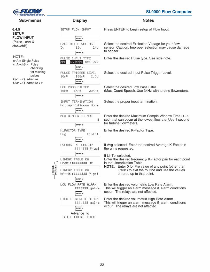
Press ENTER to begin setup of Flow Input.
Select the desired Excitation Voltage for your flowsensor. Caution: Improper selection may cause damageto sensor
Enter the desired Pulse type. See side note.
Select the desired Input Pulse Trigger Level.
Select the desired Low Pass Filter.(Max. Count Speed). Use 3kHz with turbine flowmeters.
Select the proper input termination.
Enter the desired Maximum Sample Window Time (1-99sec) that can occur at the lowest flowrate. Use 1 secondfor turbine flowmeters.
Enter the desired K-Factor Type.
If Avg selected, Enter the desired Average K-Factor inthe units requested.
If LinTbl selected,Enter the desired frequency/ K-Factor pair for each pointin the Linearization Table.NOTE: Enter 0 for Fre value of any point (other than
Fre01) to exit the routine and use the valuesentered up to that point.
Enter the desired volumetric Low Rate Alarm.This will trigger an alarm message if alarm conditionsoccur. The relays are not affected.
Enter the desired volumetric High Rate Alarm.This will trigger an alarm message if alarm conditionsoccur. The relays are not affected.
6.4.5SETUPFLOW INPUT(Pulse - chA &chA=chB)
NOTE:chA = Single PulsechA=chB = Pulse
checkingfor missingpulses
Qx1 = QuadratureQx2 = Quadrature x 2
NotesDisplaySub-menus
ENTER
ENTER
ENTER
ENTER
ENTER
ENTER
ENTER
ENTER
ENTER
ENTER
ENTER
ENTER
Thr
ough
16 P
oint
s
23
SL9000 Flow Computer
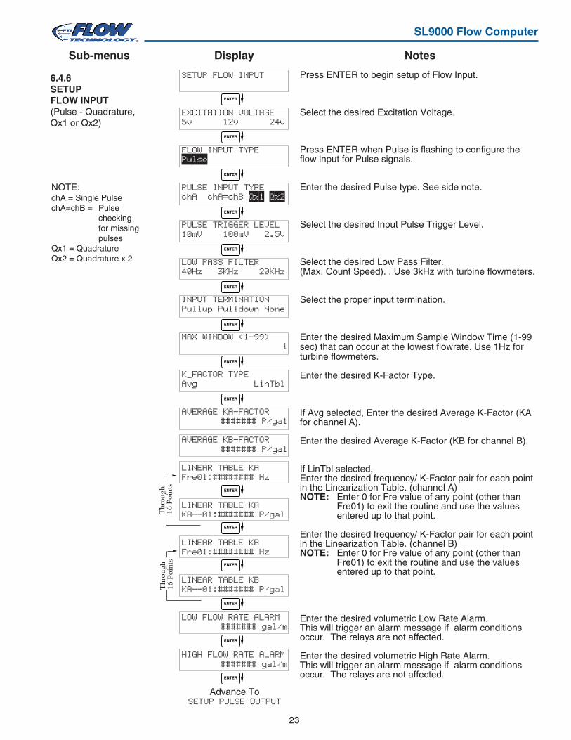
6.4.6SETUPFLOW INPUT(Pulse - Quadrature,Qx1 or Qx2)
SETUP FLOW INPUT
EXCITATION VOLTAGE5v 12v 24v
FLOW INPUT TYPEPulse
PULSE INPUT TYPEchA chA=chB Qx1 Qx2
PULSE TRIGGER LEVEL10mV 100mV 2.5V
LOW PASS FILTER40Hz 3KHz 20KHz
INPUT TERMINATIONPullup Pulldown None
MAX WINDOW (1-99)1
K_FACTOR TYPEAvg LinTbl
AVERAGE KA-FACTOR####### P/gal
AVERAGE KB-FACTOR####### P/gal
LINEAR TABLE KAFre01:######## Hz
LINEAR TABLE KAKA--01:####### P/gal
LINEAR TABLE KBFre01:######## Hz
LINEAR TABLE KBKA--01:####### P/gal
LOW FLOW RATE ALARM ####### gal/m
HIGH FLOW RATE ALARM####### gal/m
Advance ToSETUP PULSE OUTPUT
Press ENTER to begin setup of Flow Input.
Select the desired Excitation Voltage.
Press ENTER when Pulse is flashing to configure theflow input for Pulse signals.
Enter the desired Pulse type. See side note.
Select the desired Input Pulse Trigger Level.
Select the desired Low Pass Filter.(Max. Count Speed). . Use 3kHz with turbine flowmeters.
Select the proper input termination.
Enter the desired Maximum Sample Window Time (1-99sec) that can occur at the lowest flowrate. Use 1Hz forturbine flowmeters.
Enter the desired K-Factor Type.
If Avg selected, Enter the desired Average K-Factor (KAfor channel A).
Enter the desired Average K-Factor (KB for channel B).
If LinTbl selected,Enter the desired frequency/ K-Factor pair for each pointin the Linearization Table. (channel A)NOTE: Enter 0 for Fre value of any point (other than
Fre01) to exit the routine and use the valuesentered up to that point.
Enter the desired frequency/ K-Factor pair for each pointin the Linearization Table. (channel B)NOTE: Enter 0 for Fre value of any point (other than
Fre01) to exit the routine and use the valuesentered up to that point.
Enter the desired volumetric Low Rate Alarm.This will trigger an alarm message if alarm conditionsoccur. The relays are not affected.
Enter the desired volumetric High Rate Alarm.This will trigger an alarm message if alarm conditionsoccur. The relays are not affected.
NotesDisplaySub-menus
ENTER
ENTER
ENTER
ENTER
ENTER
ENTER
ENTER
ENTER
ENTER
ENTER
ENTER
ENTER
ENTER
ENTER
ENTER
Thr
ough
16 P
oint
sT
hrou
gh16
Poi
nts
NOTE:chA = Single PulsechA=chB = Pulse
checkingfor missingpulses
Qx1 = QuadratureQx2 = Quadrature x 2
24
SL9000 Flow Computer
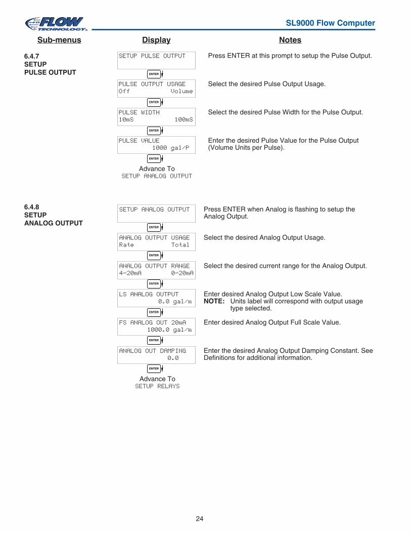
6.4.7SETUPPULSE OUTPUT
Press ENTER at this prompt to setup the Pulse Output.
Select the desired Pulse Output Usage.
Select the desired Pulse Width for the Pulse Output.
Enter the desired Pulse Value for the Pulse Output(Volume Units per Pulse).
6.4.8SETUPANALOG OUTPUT
Press ENTER when Analog is flashing to setup theAnalog Output.
Select the desired Analog Output Usage.
Select the desired current range for the Analog Output.
Enter desired Analog Output Low Scale Value.NOTE: Units label will correspond with output usage
type selected.
Enter desired Analog Output Full Scale Value.
Enter the desired Analog Output Damping Constant. SeeDefinitions for additional information.
ENTER
ENTER
ENTER
ENTER
SETUP PULSE OUTPUT
PULSE OUTPUT USAGEOff Volume
PULSE WIDTH10mS 100mS
PULSE VALUE 1000 gal/P
Advance ToSETUP ANALOG OUTPUT
SETUP ANALOG OUTPUT
ANALOG OUTPUT USAGERate Total
ANALOG OUTPUT RANGE4-20mA 0-20mA
LS ANALOG OUTPUT 0.0 gal/m
FS ANALOG OUT 20mA 1000.0 gal/m
ANALOG OUT DAMPING 0.0
Advance ToSETUP RELAYS
ENTER
ENTER
ENTER
ENTER
ENTER
ENTER
NotesDisplaySub-menus
25
SL9000 Flow Computer
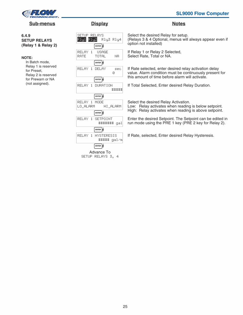
6.4.9SETUP RELAYS(Relay 1 & Relay 2)
Select the desired Relay for setup.(Relays 3 & 4 Optional, menus will always appear even ifoption not installed)
If Relay 1 or Relay 2 Selected,Select Rate, Total or NA.
If Rate selected, enter desired relay activation delayvalue. Alarm condition must be continuously present forthis amount of time before alarm will activate.
If Total Selected, Enter desired Relay Duration.
Select the desired Relay Activation.Low: Relay activates when reading is below setpoint.High: Relay activates when reading is above setpoint.
Enter the desired Setpoint. The Setpoint can be edited inrun mode using the PRE 1 key (PRE 2 key for Relay 2).
If Rate, selected, Enter desired Relay Hysteresis.
NOTE:In Batch mode,Relay 1 is reservedfor Preset,Relay 2 is reservedfor Prewarn or NA(not assigned).
SETUP RELAYSRly1 Rly2 Rly3 Rly4
RELAY 1 USAGERATE TOTAL NA
RELAY 1 DELAY sec 0
RELAY 1 DURATION#####
RELAY 1 MODELO_ALARM HI_ALARM
RELAY 1 SETPOINT####### gal
RELAY 1 HYSTERESIS##### gal/m
Advance ToSETUP RELAYS 3, 4
ENTER
ENTER
ENTER
ENTER
ENTER
ENTER
ENTER
NotesDisplaySub-menus
26
SL9000 Flow Computer
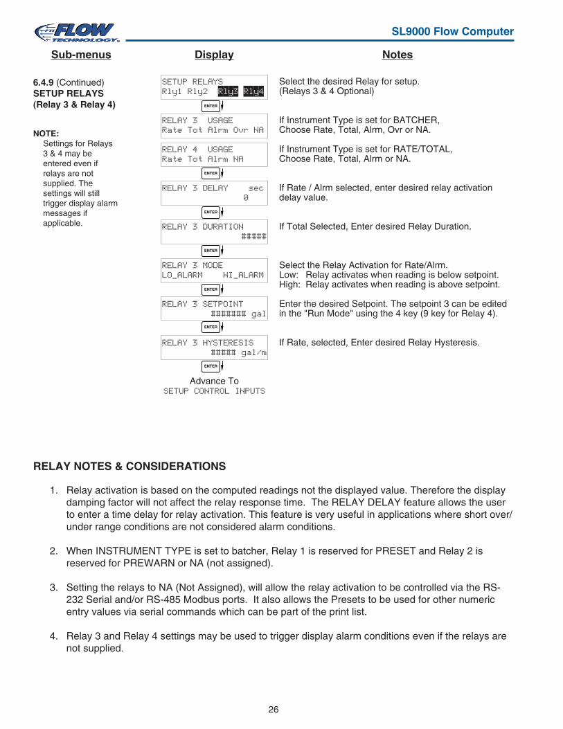
6.4.9 (Continued)SETUP RELAYS(Relay 3 & Relay 4)
Select the desired Relay for setup.(Relays 3 & 4 Optional)
If Instrument Type is set for BATCHER,Choose Rate, Total, Alrm, Ovr or NA.
If Instrument Type is set for RATE/TOTAL,Choose Rate, Total, Alrm or NA.
If Rate / Alrm selected, enter desired relay activationdelay value.
If Total Selected, Enter desired Relay Duration.
Select the Relay Activation for Rate/Alrm.Low: Relay activates when reading is below setpoint.High: Relay activates when reading is above setpoint.
Enter the desired Setpoint. The setpoint 3 can be editedin the "Run Mode" using the 4 key (9 key for Relay 4).
If Rate, selected, Enter desired Relay Hysteresis.
NOTE:Settings for Relays3 & 4 may beentered even ifrelays are notsupplied. Thesettings will stilltrigger display alarmmessages ifapplicable.
RELAY NOTES & CONSIDERATIONS
1. Relay activation is based on the computed readings not the displayed value. Therefore the displaydamping factor will not affect the relay response time. The RELAY DELAY feature allows the userto enter a time delay for relay activation. This feature is very useful in applications where short over/under range conditions are not considered alarm conditions.
2. When INSTRUMENT TYPE is set to batcher, Relay 1 is reserved for PRESET and Relay 2 isreserved for PREWARN or NA (not assigned).
3. Setting the relays to NA (Not Assigned), will allow the relay activation to be controlled via the RS-232 Serial and/or RS-485 Modbus ports. It also allows the Presets to be used for other numericentry values via serial commands which can be part of the print list.
4. Relay 3 and Relay 4 settings may be used to trigger display alarm conditions even if the relays arenot supplied.
SETUP RELAYSRly1 Rly2 Rly3 Rly4
RELAY 3 USAGERate Tot Alrm Ovr NA
RELAY 4 USAGERate Tot Alrm NA
RELAY 3 DELAY sec 0
RELAY 3 DURATION#####
RELAY 3 MODELO_ALARM HI_ALARM
RELAY 3 SETPOINT####### gal
RELAY 3 HYSTERESIS##### gal/m
Advance ToSETUP CONTROL INPUTS
ENTER
ENTER
ENTER
ENTER
ENTER
ENTER
ENTER
NotesDisplaySub-menus
27
SL9000 Flow Computer
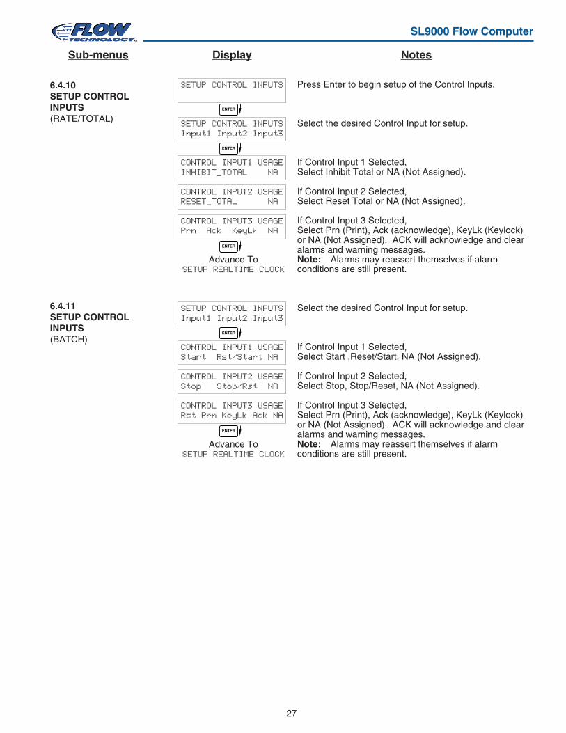
6.4.10SETUP CONTROLINPUTS(RATE/TOTAL)
Press Enter to begin setup of the Control Inputs.
Select the desired Control Input for setup.
If Control Input 1 Selected,Select Inhibit Total or NA (Not Assigned).
If Control Input 2 Selected,Select Reset Total or NA (Not Assigned).
If Control Input 3 Selected,Select Prn (Print), Ack (acknowledge), KeyLk (Keylock)or NA (Not Assigned). ACK will acknowledge and clearalarms and warning messages.Note: Alarms may reassert themselves if alarmconditions are still present.
Select the desired Control Input for setup.
If Control Input 1 Selected,Select Start ,Reset/Start, NA (Not Assigned).
If Control Input 2 Selected,Select Stop, Stop/Reset, NA (Not Assigned).
If Control Input 3 Selected,Select Prn (Print), Ack (acknowledge), KeyLk (Keylock)or NA (Not Assigned). ACK will acknowledge and clearalarms and warning messages.Note: Alarms may reassert themselves if alarmconditions are still present.
6.4.11SETUP CONTROLINPUTS(BATCH)
SETUP CONTROL INPUTS
SETUP CONTROL INPUTSInput1 Input2 Input3
CONTROL INPUT1 USAGEINHIBIT_TOTAL NA
CONTROL INPUT2 USAGERESET_TOTAL NA
CONTROL INPUT3 USAGEPrn Ack KeyLk NA
Advance ToSETUP REALTIME CLOCK
SETUP CONTROL INPUTSInput1 Input2 Input3
CONTROL INPUT1 USAGEStart Rst/Start NA
CONTROL INPUT2 USAGEStop Stop/Rst NA
CONTROL INPUT3 USAGERst Prn KeyLk Ack NA
Advance ToSETUP REALTIME CLOCK
ENTER
ENTER
ENTER
ENTER
ENTER
NotesDisplaySub-menus
28
SL9000 Flow Computer
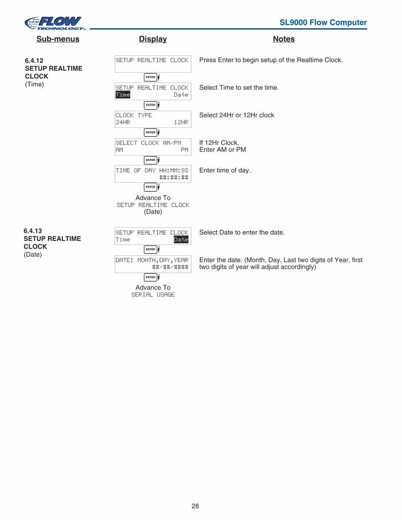
Press Enter to begin setup of the Realtime Clock.
Select Time to set the time.
Select 24Hr or 12Hr clock
If 12Hr Clock,Enter AM or PM
Enter time of day.
Select Date to enter the date.
Enter the date. (Month, Day, Last two digits of Year, firsttwo digits of year will adjust accordingly)
6.4.13SETUP REALTIMECLOCK(Date)
6.4.12SETUP REALTIMECLOCK(Time)
SETUP REALTIME CLOCK
SETUP REALTIME CLOCKTime Date
CLOCK TYPE24HR 12HR
SELECT CLOCK AM/PMAM PM
TIME OF DAY HH:MM:SS ##:##:##
Advance ToSETUP REALTIME CLOCK
(Date)
SETUP REALTIME CLOCKTime Date
DATE: MONTH,DAY,YEAR ##/##/####
Advance ToSERIAL USAGE
ENTER
ENTER
ENTER
ENTER
ENTER
ENTER
ENTER
NotesDisplaySub-menus
29
SL9000 Flow Computer
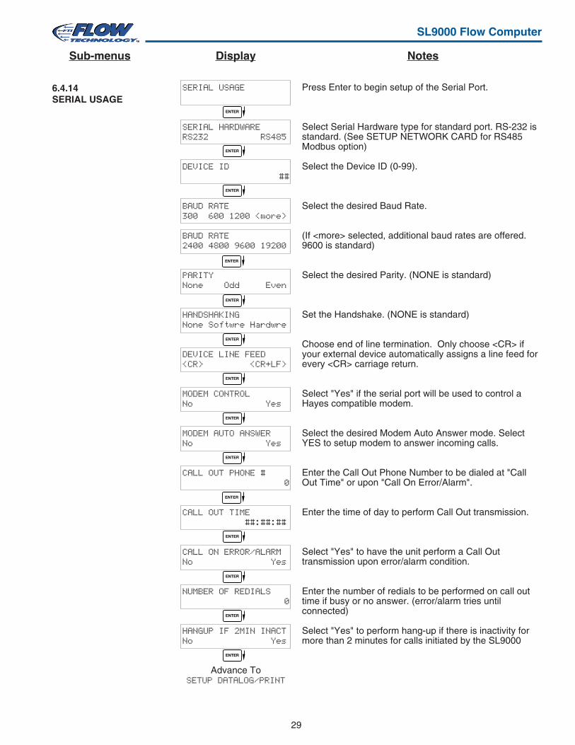
6.4.14SERIAL USAGE
Press Enter to begin setup of the Serial Port.
Select Serial Hardware type for standard port. RS-232 isstandard. (See SETUP NETWORK CARD for RS485Modbus option)
Select the Device ID (0-99).
Select the desired Baud Rate.
(If <more> selected, additional baud rates are offered.9600 is standard)
Select the desired Parity. (NONE is standard)
Set the Handshake. (NONE is standard)
Choose end of line termination. Only choose <CR> ifyour external device automatically assigns a line feed forevery <CR> carriage return.
Select "Yes" if the serial port will be used to control aHayes compatible modem.
Select the desired Modem Auto Answer mode. SelectYES to setup modem to answer incoming calls.
Enter the Call Out Phone Number to be dialed at "CallOut Time" or upon "Call On Error/Alarm".
Enter the time of day to perform Call Out transmission.
Select "Yes" to have the unit perform a Call Outtransmission upon error/alarm condition.
Enter the number of redials to be performed on call outtime if busy or no answer. (error/alarm tries untilconnected)
Select "Yes" to perform hang-up if there is inactivity formore than 2 minutes for calls initiated by the SL9000
SERIAL USAGE
SERIAL HARDWARERS232 RS485
DEVICE ID ##
BAUD RATE300 600 1200 <more>
BAUD RATE2400 4800 9600 19200
PARITYNone Odd Even
HANDSHAKINGNone Softwre Hardwre
DEVICE LINE FEED<CR> <CR+LF>
MODEM CONTROLNo Yes
MODEM AUTO ANSWERNo Yes
CALL OUT PHONE # 0
CALL OUT TIME ##:##:##
CALL ON ERROR/ALARMNo Yes
NUMBER OF REDIALS 0
HANGUP IF 2MIN INACTNo Yes
Advance ToSETUP DATALOG/PRINT
ENTER
ENTER
ENTER
ENTER
ENTER
ENTER
ENTER
ENTER
ENTER
ENTER
ENTER
ENTER
ENTER
ENTER
NotesDisplaySub-menus
30
SL9000 Flow Computer
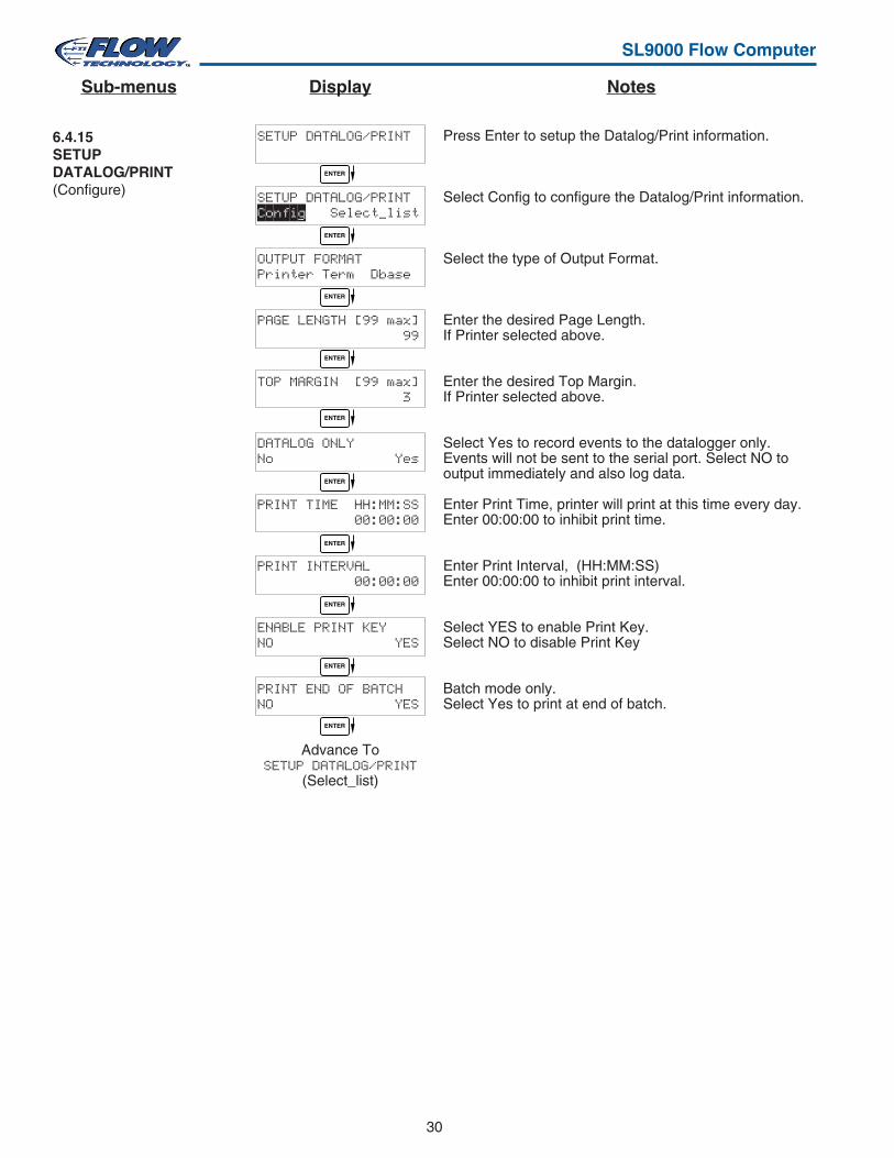
Press Enter to setup the Datalog/Print information.
Select Config to configure the Datalog/Print information.
Select the type of Output Format.
Enter the desired Page Length.If Printer selected above.
Enter the desired Top Margin.If Printer selected above.
Select Yes to record events to the datalogger only.Events will not be sent to the serial port. Select NO tooutput immediately and also log data.
Enter Print Time, printer will print at this time every day.Enter 00:00:00 to inhibit print time.
Enter Print Interval, (HH:MM:SS)Enter 00:00:00 to inhibit print interval.
Select YES to enable Print Key.Select NO to disable Print Key
Batch mode only.Select Yes to print at end of batch.
6.4.15SETUPDATALOG/PRINT(Configure)
SETUP DATALOG/PRINT
SETUP DATALOG/PRINTConfig Select_list
OUTPUT FORMATPrinter Term Dbase
PAGE LENGTH [99 max] 99
TOP MARGIN [99 max] 3
DATALOG ONLYNo Yes
PRINT TIME HH:MM:SS 00:00:00
PRINT INTERVAL 00:00:00
ENABLE PRINT KEYNO YES
PRINT END OF BATCHNO YES
Advance ToSETUP DATALOG/PRINT
(Select_list)
ENTER
ENTER
ENTER
ENTER
ENTER
ENTER
ENTER
ENTER
ENTER
ENTER
NotesDisplaySub-menus
31
SL9000 Flow Computer
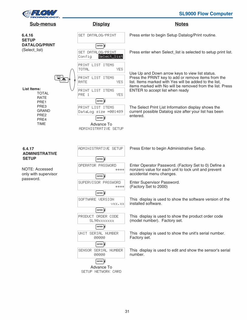
Press Enter to begin Administrative Setup.
Enter Operator Password. (Factory Set to 0) Define anonzero value for each unit to lock unit and preventaccidental menu changes.
Enter Supervisor Password.(Factory Set to 2000)
This display is used to show the software version of theinstalled software.
This display is used to show the product order code(model number). Factory set.
This display is used to show the unit's serial number.Factory set.
This display is used to edit and show the sensor's serialnumber.
6.4.17ADMINISTRATIVESETUP
6.4.16SETUPDATALOG/PRINT(Select_list)
Press enter to begin Setup Datalog/Print routine.
Press enter when Select_list is selected to setup print list.
Use Up and Down arrow keys to view list status.Press the PRINT key to add or remove items from thelist. Items marked with Yes will be added to the list,items marked with No will be removed from the list. PressENTER to accept list when ready
The Select Print List Information display shows thecurrent possible Datalog size after your list has beenentered.
STOP
START
List Items:TOTALRATEPRE1PRE3GRANDPRE2PRE4TIME
NOTE: Accessedonly with supervisorpassword.
SET DATALOG/PRINT
SET DATALOG/PRINTConfig Select_list
PRINT LIST ITEMSTOTAL YES
PRINT LIST ITEMSRATE YES
PRINT LIST ITEMSPRE 1 YES
PRINT LIST ITEMSDataLog size =001489
Advance ToADMINISTRATIVE SETUP
ENTER
ENTER
ENTER
ADMINISTRATIVE SETUP
OPERATOR PASSWORD****
SUPERVISOR PASSWORD****
SOFTWARE VERSIONvxx.xx
PRODUCT ORDER CODE SL90xxxxxxx
UNIT SERIAL NUMBER 00000
SENSOR SERIAL NUMBER 00000
Advance ToSETUP NETWORK CARD
ENTER
ENTER
ENTER
ENTER
ENTER
ENTER
ENTER
NotesDisplaySub-menus
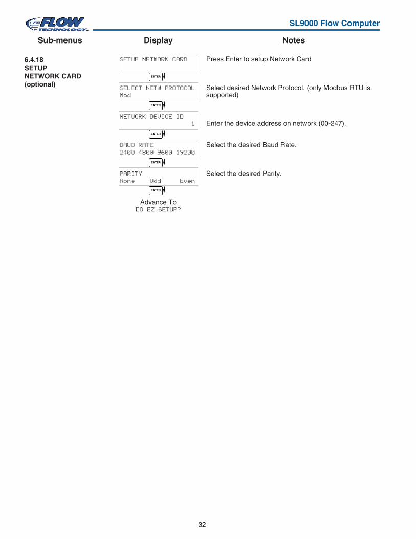
32
SL9000 Flow Computer
6.4.18SETUPNETWORK CARD(optional)
Press Enter to setup Network Card
Select desired Network Protocol. (only Modbus RTU issupported)
Enter the device address on network (00-247).
Select the desired Baud Rate.
Select the desired Parity.
SETUP NETWORK CARD
SELECT NETW PROTOCOLMod
NETWORK DEVICE ID 1
BAUD RATE2400 4800 9600 19200
PARITYNone Odd Even
Advance ToDO EZ SETUP?
ENTER
ENTER
ENTER
ENTER
ENTER
NotesDisplaySub-menus
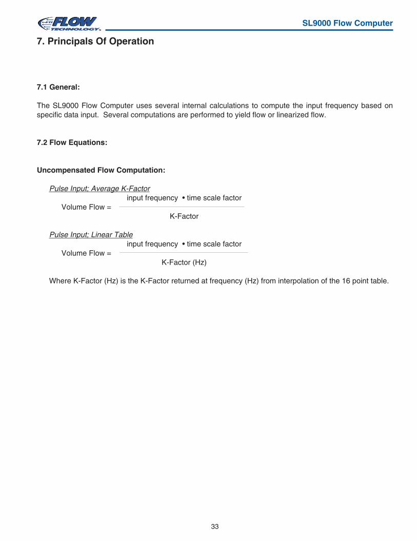
33
SL9000 Flow Computer
7.1 General:
The SL9000 Flow Computer uses several internal calculations to compute the input frequency based onspecific data input. Several computations are performed to yield flow or linearized flow.
7.2 Flow Equations:
Uncompensated Flow Computation:
Pulse Input; Average K-Factorinput frequency • time scale factor
Volume Flow =K-Factor
Pulse Input; Linear Tableinput frequency • time scale factor
Volume Flow =K-Factor (Hz)
Where K-Factor (Hz) is the K-Factor returned at frequency (Hz) from interpolation of the 16 point table.
7. Principals Of Operation
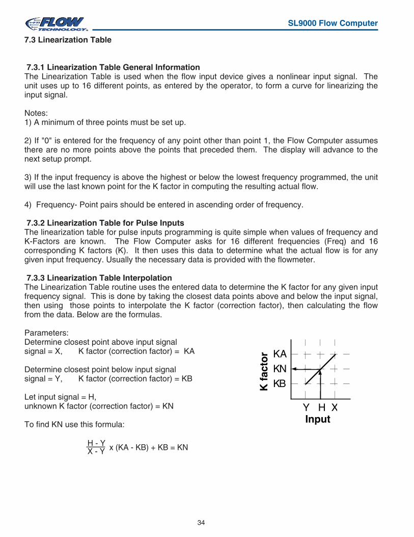
34
SL9000 Flow Computer
7.3 Linearization Table
7.3.1 Linearization Table General InformationThe Linearization Table is used when the flow input device gives a nonlinear input signal. Theunit uses up to 16 different points, as entered by the operator, to form a curve for linearizing theinput signal.
Notes:1) A minimum of three points must be set up.
2) If "0" is entered for the frequency of any point other than point 1, the Flow Computer assumesthere are no more points above the points that preceded them. The display will advance to thenext setup prompt.
3) If the input frequency is above the highest or below the lowest frequency programmed, the unitwill use the last known point for the K factor in computing the resulting actual flow.
4) Frequency- Point pairs should be entered in ascending order of frequency.
7.3.2 Linearization Table for Pulse InputsThe linearization table for pulse inputs programming is quite simple when values of frequency andK-Factors are known. The Flow Computer asks for 16 different frequencies (Freq) and 16corresponding K factors (K). It then uses this data to determine what the actual flow is for anygiven input frequency. Usually the necessary data is provided with the flowmeter.
7.3.3 Linearization Table InterpolationThe Linearization Table routine uses the entered data to determine the K factor for any given inputfrequency signal. This is done by taking the closest data points above and below the input signal,then using those points to interpolate the K factor (correction factor), then calculating the flowfrom the data. Below are the formulas.
Parameters:Determine closest point above input signalsignal = X, K factor (correction factor) = KA
Determine closest point below input signalsignal = Y, K factor (correction factor) = KB
Let input signal = H,unknown K factor (correction factor) = KN
To find KN use this formula:
KAKNKB
Y H XInput
K f
acto
r
x (KA - KB) + KB = KNH - YX - Y
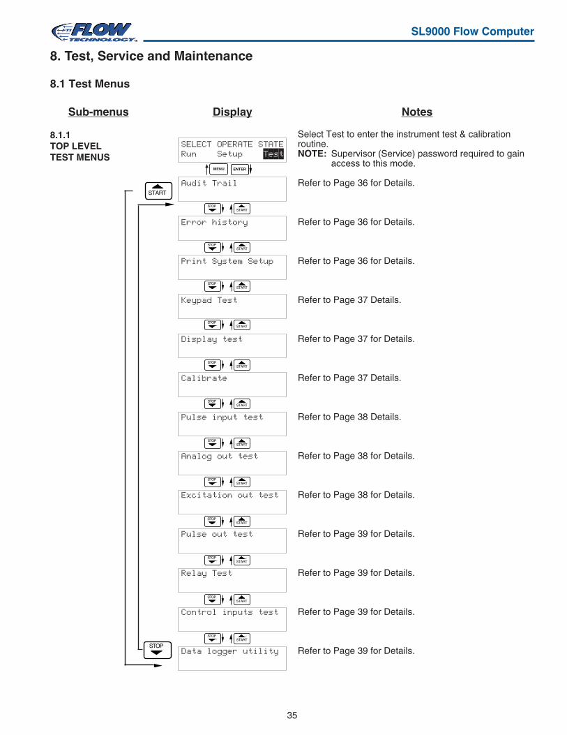
35
SL9000 Flow Computer
8.1 Test Menus
8.1.1TOP LEVELTEST MENUS
START
Select Test to enter the instrument test & calibrationroutine.NOTE: Supervisor (Service) password required to gain
access to this mode.
Refer to Page 36 for Details.
Refer to Page 36 for Details.
Refer to Page 36 for Details.
Refer to Page 37 Details.
Refer to Page 37 for Details.
Refer to Page 37 Details.
Refer to Page 38 Details.
Refer to Page 38 for Details.
Refer to Page 38 for Details.
Refer to Page 39 for Details.
Refer to Page 39 for Details.
Refer to Page 39 for Details.
Refer to Page 39 for Details.
8. Test, Service and Maintenance
SELECT OPERATE STATERun Setup Test
Audit Trail
Error history
Print System Setup
Keypad Test
Display test
Calibrate
Pulse input test
Analog out test
Excitation out test
Pulse out test
Relay Test
Control inputs test
Data logger utility
STARTSTOP
ENTERMENU
STARTSTOP
STARTSTOP
STARTSTOP
STARTSTOP
STARTSTOP
STARTSTOP
STARTSTOP
STARTSTOP
STARTSTOP
STARTSTOP
STARTSTOP
STOP
NotesDisplaySub-menus
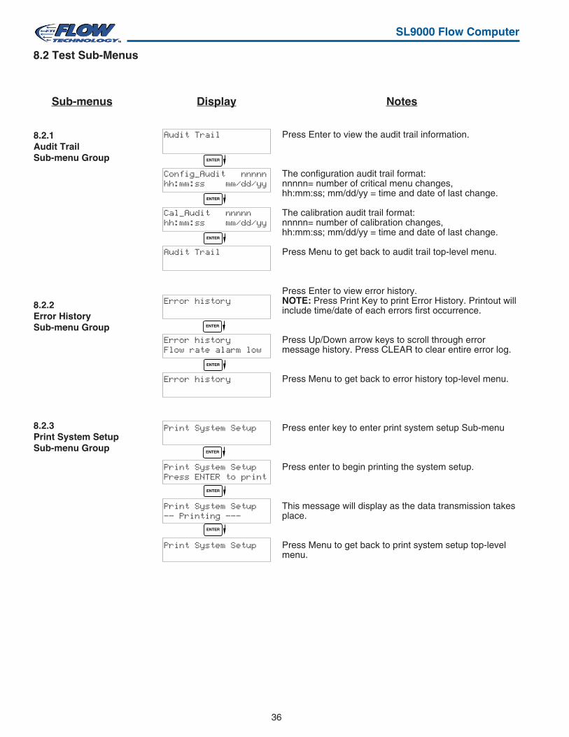
36
SL9000 Flow Computer
Press Enter to view the audit trail information.
The configuration audit trail format:nnnnn= number of critical menu changes,hh:mm:ss; mm/dd/yy = time and date of last change.
The calibration audit trail format:nnnnn= number of calibration changes,hh:mm:ss; mm/dd/yy = time and date of last change.
Press Menu to get back to audit trail top-level menu.
Press Enter to view error history.NOTE: Press Print Key to print Error History. Printout willinclude time/date of each errors first occurrence.
Press Up/Down arrow keys to scroll through errormessage history. Press CLEAR to clear entire error log.
Press Menu to get back to error history top-level menu.
Press enter key to enter print system setup Sub-menu
Press enter to begin printing the system setup.
This message will display as the data transmission takesplace.
Press Menu to get back to print system setup top-levelmenu.
8.2.1Audit TrailSub-menu Group
8.2.2Error HistorySub-menu Group
8.2.3Print System SetupSub-menu Group
8.2 Test Sub-Menus
Audit Trail
Config_Audit nnnnnhh:mm:ss mm/dd/yy
Cal_Audit nnnnnhh:mm:ss mm/dd/yy
Audit Trail
Error history
Error historyFlow rate alarm low
Error history
Print System Setup
Print System SetupPress ENTER to print
Print System Setup—— Printing ——-
Print System Setup
ENTER
ENTER
ENTER
ENTER
ENTER
ENTER
ENTER
ENTER
NotesDisplaySub-menus
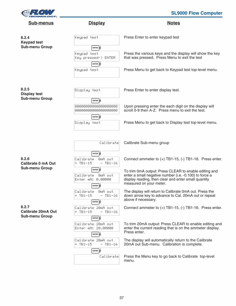
37
SL9000 Flow Computer
8.2.6Calibrate 0 mA OutSub-menu Group
8.2.7Calibrate 20mA OutSub-menu Group
8.2.4Keypad testSub-menu Group
8.2.5Display testSub-menu Group
Press Enter to enter keypad test
Press the various keys and the display will show the keythat was pressed. Press Menu to exit the test
Press Menu to get back to Keypad test top-level menu.
Press Enter to enter display test.
Upon pressing enter the each digit on the display willscroll 0-9 then A-Z. Press menu to exit the test.
Press Menu to get back to Display test top-level menu.
Calibrate Sub-menu group
Connect ammeter to (+) TB1-15, (-) TB1-16. Press enter.
To trim 0mA output: Press CLEAR to enable editing andenter a small negative number (i.e. -0.100) to force adisplay reading, then clear and enter small quantitymeasured on your meter.
The display will return to Calibrate 0mA out. Press thedown arrow key to advance to Cal. 20mA out or repeatabove if necessary.
Connect ammeter to (+) TB1-15, (-) TB1-16. Press enter.
To trim 20mA output: Press CLEAR to enable editing andenter the current reading that is on the ammeter display.Press enter.
The display will automatically return to the Calibrate20mA out Sub-menu. Calibration is complete.
Press the Menu key to go back to Calibrate top-levelmenu.
Keypad test
Keypad testKey pressed—> ENTER
Keypad test
Display test
0000000000000000000000000000000000000000
Display test
Calibrate
Calibrate 0mA out+ TB1-15 - TB1-16
Calibrate 0mA outEnter mA: 0.00000
Calibrate 0mA out+ TB1-15 - TB1-16
Calibrate 20mA out+ TB1-15 - TB1-16
Calibrate 20mA outEnter mA: 20.00000
Calibrate 20mA out+ TB1-15 - TB1-16
Calibrate
ENTER
ENTER
ENTER
ENTER
ENTER
ENTER
ENTER
ENTER
ENTER
ENTER
NotesDisplaySub-menus
ENTER
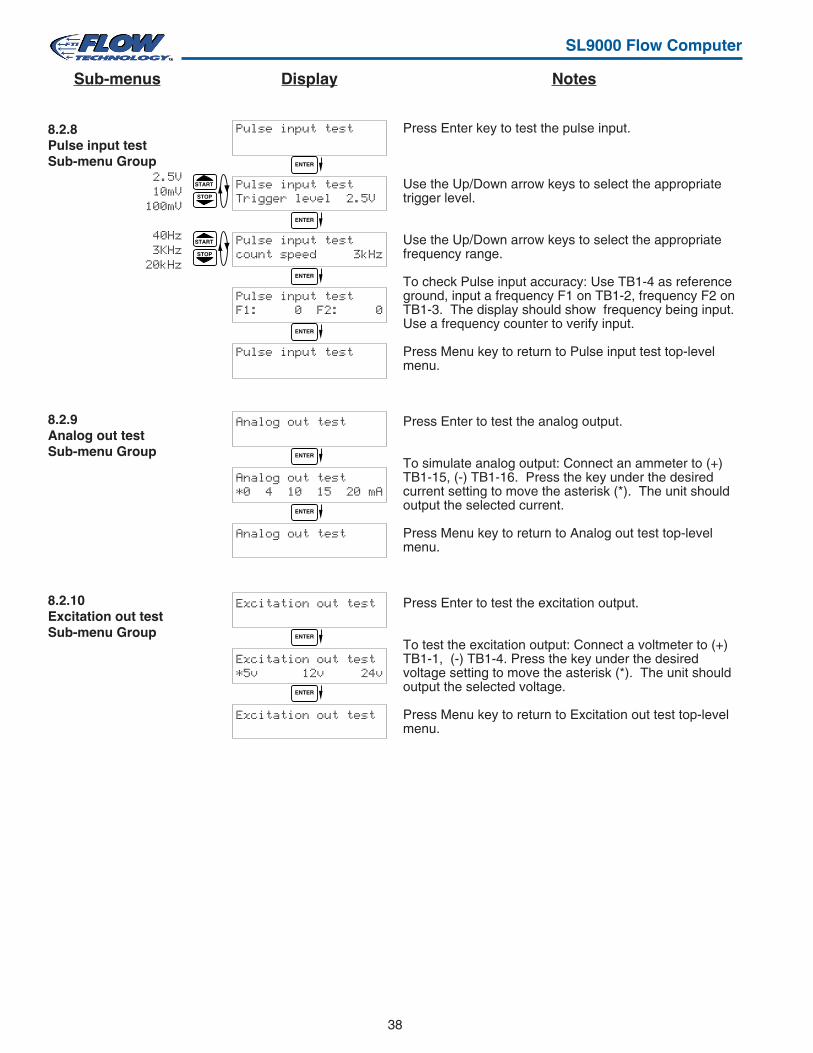
38
SL9000 Flow Computer
Press Enter key to test the pulse input.
Use the Up/Down arrow keys to select the appropriatetrigger level.
Use the Up/Down arrow keys to select the appropriatefrequency range.
To check Pulse input accuracy: Use TB1-4 as referenceground, input a frequency F1 on TB1-2, frequency F2 onTB1-3. The display should show frequency being input.Use a frequency counter to verify input.
Press Menu key to return to Pulse input test top-levelmenu.
Press Enter to test the analog output.
To simulate analog output: Connect an ammeter to (+)TB1-15, (-) TB1-16. Press the key under the desiredcurrent setting to move the asterisk (*). The unit shouldoutput the selected current.
Press Menu key to return to Analog out test top-levelmenu.
Press Enter to test the excitation output.
To test the excitation output: Connect a voltmeter to (+)TB1-1, (-) TB1-4. Press the key under the desiredvoltage setting to move the asterisk (*). The unit shouldoutput the selected voltage.
Press Menu key to return to Excitation out test top-levelmenu.
8.2.8Pulse input testSub-menu Group
8.2.10Excitation out testSub-menu Group
STOP
START2.5V10mV
100mV
40Hz3KHz
20kHz
8.2.9Analog out testSub-menu Group
Pulse input test
Pulse input testTrigger level 2.5V
Pulse input testcount speed 3kHz
Pulse input testF1: 0 F2: 0
Pulse input test
Analog out test
Analog out test*0 4 10 15 20 mA
Analog out test
Excitation out test
Excitation out test*5v 12v 24v
Excitation out test
ENTER
ENTER
ENTER
ENTER
ENTER
ENTER
ENTER
ENTER
STOP
START
NotesDisplaySub-menus
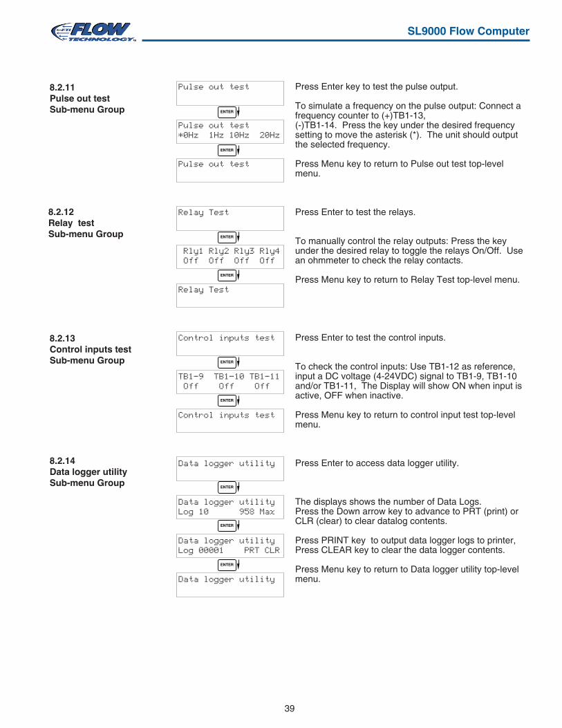
39
SL9000 Flow Computer
8.2.11Pulse out testSub-menu Group
Press Enter key to test the pulse output.
To simulate a frequency on the pulse output: Connect afrequency counter to (+)TB1-13,(-)TB1-14. Press the key under the desired frequencysetting to move the asterisk (*). The unit should outputthe selected frequency.
Press Menu key to return to Pulse out test top-levelmenu.
Press Enter to test the relays.
To manually control the relay outputs: Press the keyunder the desired relay to toggle the relays On/Off. Usean ohmmeter to check the relay contacts.
Press Menu key to return to Relay Test top-level menu.
Press Enter to test the control inputs.
To check the control inputs: Use TB1-12 as reference,input a DC voltage (4-24VDC) signal to TB1-9, TB1-10and/or TB1-11, The Display will show ON when input isactive, OFF when inactive.
Press Menu key to return to control input test top-levelmenu.
Press Enter to access data logger utility.
The displays shows the number of Data Logs.Press the Down arrow key to advance to PRT (print) orCLR (clear) to clear datalog contents.
Press PRINT key to output data logger logs to printer,Press CLEAR key to clear the data logger contents.
Press Menu key to return to Data logger utility top-levelmenu.
8.2.12Relay testSub-menu Group
8.2.13Control inputs testSub-menu Group
8.2.14Data logger utilitySub-menu Group
Pulse out test
Pulse out test*0Hz 1Hz 10Hz 20Hz
Pulse out test
Relay Test
Rly1 Rly2 Rly3 Rly4 Off Off Off Off
Relay Test
Control inputs test
TB1-9 TB1-10 TB1-11 Off Off Off
Control inputs test
Data logger utility
Data logger utilityLog 10 958 Max
Data logger utilityLog 00001 PRT CLR
Data logger utility
ENTER
ENTER
ENTER
ENTER
ENTER
ENTER
ENTER
ENTER
ENTER
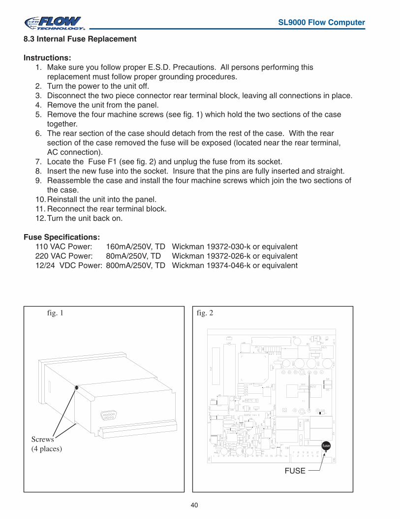
40
SL9000 Flow Computer
8.3 Internal Fuse Replacement
Instructions:1. Make sure you follow proper E.S.D. Precautions. All persons performing this
replacement must follow proper grounding procedures.2. Turn the power to the unit off.3. Disconnect the two piece connector rear terminal block, leaving all connections in place.4. Remove the unit from the panel.5. Remove the four machine screws (see fig. 1) which hold the two sections of the case
together.6. The rear section of the case should detach from the rest of the case. With the rear
section of the case removed the fuse will be exposed (located near the rear terminal,AC connection).
7. Locate the Fuse F1 (see fig. 2) and unplug the fuse from its socket.8. Insert the new fuse into the socket. Insure that the pins are fully inserted and straight.9. Reassemble the case and install the four machine screws which join the two sections of
the case.10.Reinstall the unit into the panel.11. Reconnect the rear terminal block.12.Turn the unit back on.
Fuse Specifications:110 VAC Power: 160mA/250V, TD Wickman 19372-030-k or equivalent220 VAC Power: 80mA/250V, TD Wickman 19372-026-k or equivalent12/24 VDC Power: 800mA/250V, TD Wickman 19374-046-k or equivalent
Screws(4 places)
fig. 1 fig. 2
FUSE
fuse
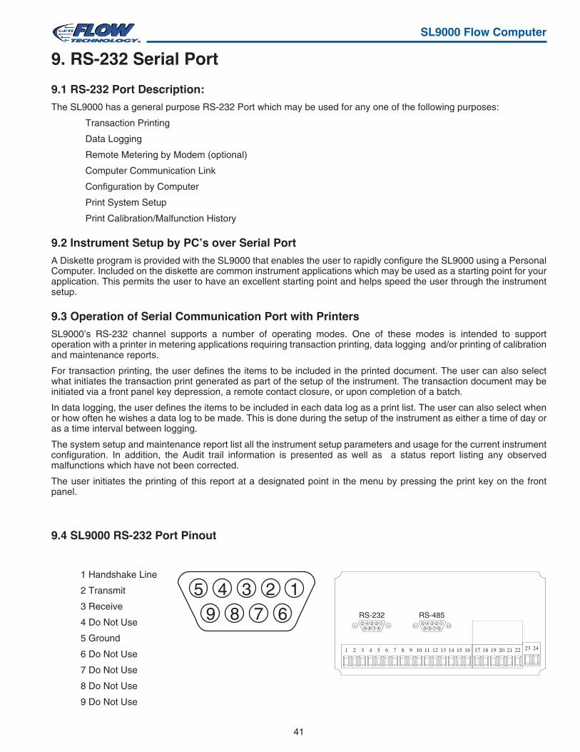
41
SL9000 Flow Computer
9. RS-232 Serial Port
9.1 RS-232 Port Description:
The SL9000 has a general purpose RS-232 Port which may be used for any one of the following purposes:
Transaction Printing
Data Logging
Remote Metering by Modem (optional)
Computer Communication Link
Configuration by Computer
Print System Setup
Print Calibration/Malfunction History
9.2 Instrument Setup by PC’s over Serial Port
A Diskette program is provided with the SL9000 that enables the user to rapidly configure the SL9000 using a PersonalComputer. Included on the diskette are common instrument applications which may be used as a starting point for yourapplication. This permits the user to have an excellent starting point and helps speed the user through the instrumentsetup.
9.3 Operation of Serial Communication Port with Printers
SL9000’s RS-232 channel supports a number of operating modes. One of these modes is intended to supportoperation with a printer in metering applications requiring transaction printing, data logging and/or printing of calibrationand maintenance reports.
For transaction printing, the user defines the items to be included in the printed document. The user can also selectwhat initiates the transaction print generated as part of the setup of the instrument. The transaction document may beinitiated via a front panel key depression, a remote contact closure, or upon completion of a batch.
In data logging, the user defines the items to be included in each data log as a print list. The user can also select whenor how often he wishes a data log to be made. This is done during the setup of the instrument as either a time of day oras a time interval between logging.
The system setup and maintenance report list all the instrument setup parameters and usage for the current instrumentconfiguration. In addition, the Audit trail information is presented as well as a status report listing any observedmalfunctions which have not been corrected.
The user initiates the printing of this report at a designated point in the menu by pressing the print key on the frontpanel.
9.4 SL9000 RS-232 Port Pinout
1 2 3 4 5 6 7 8 9 10 11 12 13 14 15 16 17 18 19 20 21 22 23 24
123456789
123456789
RS-232 RS-485
1 Handshake Line
2 Transmit
3 Receive
4 Do Not Use
5 Ground
6 Do Not Use
7 Do Not Use
8 Do Not Use
9 Do Not Use
123456789
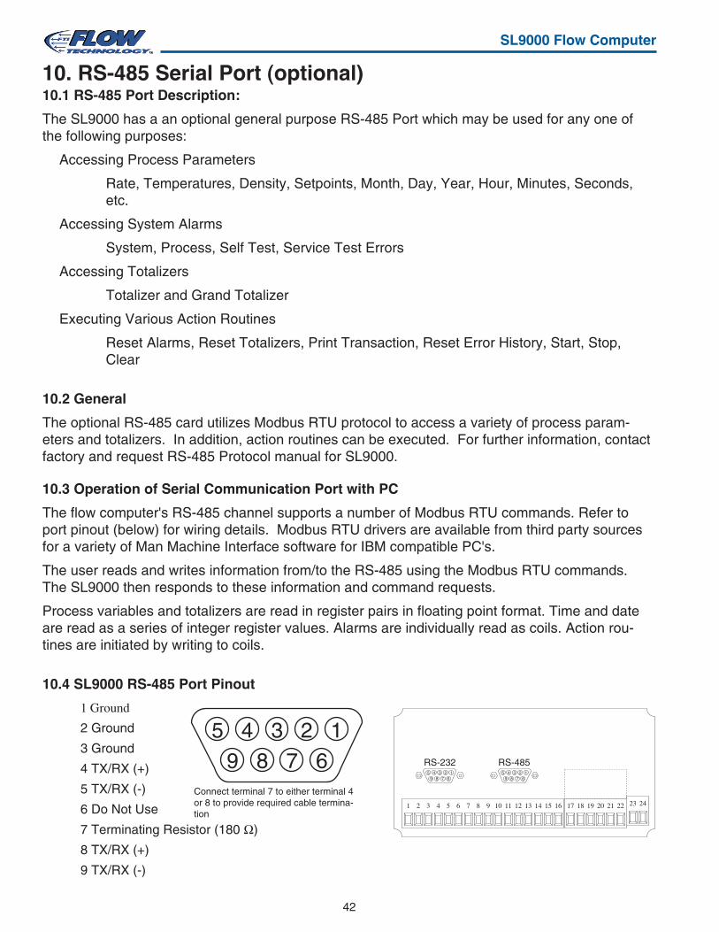
42
SL9000 Flow Computer
10. RS-485 Serial Port (optional)10.1 RS-485 Port Description:
The SL9000 has a an optional general purpose RS-485 Port which may be used for any one ofthe following purposes:
Accessing Process Parameters
Rate, Temperatures, Density, Setpoints, Month, Day, Year, Hour, Minutes, Seconds,etc.
Accessing System Alarms
System, Process, Self Test, Service Test Errors
Accessing Totalizers
Totalizer and Grand Totalizer
Executing Various Action Routines
Reset Alarms, Reset Totalizers, Print Transaction, Reset Error History, Start, Stop,Clear
10.2 General
The optional RS-485 card utilizes Modbus RTU protocol to access a variety of process param-eters and totalizers. In addition, action routines can be executed. For further information, contactfactory and request RS-485 Protocol manual for SL9000.
10.3 Operation of Serial Communication Port with PC
The flow computer's RS-485 channel supports a number of Modbus RTU commands. Refer toport pinout (below) for wiring details. Modbus RTU drivers are available from third party sourcesfor a variety of Man Machine Interface software for IBM compatible PC's.
The user reads and writes information from/to the RS-485 using the Modbus RTU commands.The SL9000 then responds to these information and command requests.
Process variables and totalizers are read in register pairs in floating point format. Time and dateare read as a series of integer register values. Alarms are individually read as coils. Action rou-tines are initiated by writing to coils.
10.4 SL9000 RS-485 Port Pinout
123456789
1 2 3 4 5 6 7 8 9 10 11 12 13 14 15 16 17 18 19 20 21 22 23 24
123456789
123456789
RS-232 RS-485
1 Ground
2 Ground
3 Ground
4 TX/RX (+)
5 TX/RX (-)
6 Do Not Use
7 Terminating Resistor (180 Ω)
8 TX/RX (+)
9 TX/RX (-)
Connect terminal 7 to either terminal 4or 8 to provide required cable termina-tion

43
SL9000 Flow Computer
11. Flow Computer Setup SoftwareThe SL9000 setup program provides for configuring, monitoring and controlling a SL9000 unit.
Sample applications are stored in disk files. The setup program calls these Templates. You can store thesetup from the program’s memory to either the SL9000 (Downloading the file) or to a disk file (Saving thefile) for later usage. Similarly you can load the setup in program memory from either a disk file (Opening afile) or from the SL9000 unit (Uploading a file).
The program can monitor outputs from the unit while it is running.
The program can reset alarms and totalizers.
For assistance there are mini-helps at the bottom of each screen in the program. There is also contextsensitive help available for each screen accessible by pressing the F1 key.
11.1 System Requirements:
IBM PC or compatible with 386 or higher class microprocessor
4 MB RAM
3 MB free disk space
VGA or higher color monitor at 640 x 480
Microsoft® Windows™ 3.1 or 3.11 or Windows 95/98™ or higher
Communication Port - RS-232
RS-232 Cable
11.2 Cable and Wiring Requirements:
The serial communication port on your PC is either a 25 pin or 9 pin connector. No cabling is supplied withthe setup software. A cable must be purchased separately or made by the user. It is recommended topurchase a modem cable which matches the available communication port on you PC and a 9 pin maleconnection for the SL9000 serial port.
11.3 Installation for Windows™
The Setup Software includes an installation program which copies the software to your hard drive.
Insert Setup Disk 1 in a floppy drive.
In the Program Manager, click File, and then select Run.
NOTE: For Windows 95™ Click the Start button, select Run and proceed as follows:
Type the floppy drive letter followed by a colon (:) and a backslash (\), and the word setup. For Example:
a:\setup
Follow the instructions on your screen.
11.4 Using the Flow Computer Setup Software
The setup software window consists of several menu “Tabs”. Each tab is organized into groups containingvarious configuration and/or monitoring functions. To view the tab windows, simply click on the tab. Theprevious tab window will be hidden as the new tab window is brought to the foreground.
44
SL9000 Flow Computer
11.5 File Tab
The File Tab has three sections. Any of the options on this tab can also be accessed from the File Sub-menu.
The Template Section provides for opening and saving templates. The Save and Save As buttonsprovide the standard Windows functionality for dealing with files. The Open button is used to open existingtemplates.
There are two additional menu items available only from the File pulldown menu: Open Existing File andOpen Template.
The Open Existing File option allows for creating custom templates using the existing template in memoryas the starting point.
The Open Template option will bring up a list of predefined templates that can be loaded into the program.These predefined templates are useful as a starting point when defining custom templates.
A typical scenario using the setup program would be the following:
• Open up a predefined template from the supplied list
• Choose ‘Save As’ to save this to a new file name
• Proceed to customize the template by making any changes that are needed
• Save the template to disk (if you want to reuse this template)
• Download the template to an attached unit.
The Communications with Flow Computer Section allows the user to upload a template file from theunit or download the program’s current template to the unit.
The Print (report) Section allows the user to:
1. Configure the current Windows printer through the Select Printer option.
2. Print a Maintenance Report through the PC's printer using the Print Maintenance option.
3. Print the current template through the PC's printer using Print Setup option.
11.6 Setup Tab
The Setup tab is where majority of the SL9000 instrument setup modifications are done. The Setup tab isdivided into five sections.
System Section: Instrument, Indicators
Input Section: Flow, Control Inputs
Output Section: Pulse, Currents
Relay Section: Relays
Other Settings Section: Administration, Serial Usage, Datalog/Printing, Time Clock
NOTE: Many setup items are enabled or disabled depending on previous setup selections, It is importantto work your way through the above list in the order shown. Be sure to verify your selections when you arethrough programming to insure that no settings were changed automatically.

45
SL9000 Flow Computer
11.7 View Tab
The View Tab screen allows for viewing selected group items on the PC in a similar format as shown onthe unit display. Data from the following groups can be viewed in the List of Values section:
Process Parameters (i.e. rate, input frequency, K-Factor, mA output)
Totalizers (i.e. total, grand total)
Version
Error Log
The setup software assumes the current setup has been uploaded from the flow computer into the PC. It isimportant that the setup program and the SL9000 unit are using the same setup information at all times orthe data will be inconsistent. It is best to upload or download the setup before using this feature.
To start the viewer, first check the boxes of items to view and then click the start button. The data willappear in the appropriate sections and will be continuously updated. The refresh rate is dependent on thenumber of items that are being viewed and the baud rate of the connection. Data in the List of Valuessection can be collapsed by clicking on the ‘minus’ sign in front of the group title. The data can beexpanded by clicking on the ‘plus’ sign in front of the group title. If a group is collapsed and data in thegroup changes on refresh, the group will automatically expand. Changing the view items requires stoppingthe current viewing, checking the new selections and then restarting the viewer.
If communication errors occur while reading data from the SL9000 device, the word ‘Error’ will appear inplace of the actual value. If the connection to the SL9000 is lost, the viewer will time out with a messagesaying the device is not responding.
The viewer will attempt to communicate with the SL9000 device matching the device ID set in thecommunications screen. If you are having trouble establishing communication, compare settings for the PCand the flow computer. Also verify the connections between the PC and flow computer.
11.8 Misc. Tab
This tab has three sections: Tools, Actions and Options.
The tools section contains various system administration activities such as creating/modifying the initialsign-on screen and/or print header:
Create Sign-on, Create Print Header
The Actions section is used to send commands to the SL9000 unit:
Reset Totalizers, Reset Alarms, Reset Alarm History
The Options section has the following selections:
Network Card Enable, Network Card Setup

46
SL9000 Flow Computer
Acknowledge & Clear AlarmsAcknowledge is used to clear alarm relays and remove any visual alarm messages from the display. In the runmode, press the ENTER key or activate CONTROL INPUT 3 (if set for ACK) to momentarily clear alarms andalarm messages. Alarms will reassert themselves if alarm conditions are still present.
Analog OutputThe analog signal (4-20mA) that is generated by the SL9000. It can correspond to the Rate or Total. This outputis used primarily for transmission of process information to remote systems.
Audit TrailThe audit trail is used to track the number of changes made to the units setup program and calibration.
Auto Batch RestartThe Auto Batch Restart function allows the user to set an amount of time to automatically restart a batch after thecompletion of a batch. This time can be set from 1 to 99 seconds.
Batch Count ModeBatch Count Mode specifies the user preference for count direction. The "Up" selection begins with a value of"0" and counts up until the batch size is reached. The "Down" selection begins with a value equal to the desiredbatch size and counts down to "0".
Batch OverrunThe SL9000 offers a batch overrun compensation routine. If batch overrun occurs due to slow valve responsetime, the unit will compensate for the overrun amount on the next batch. This feature can be disabled if desired.NOTE: A nonzero MAX DRAIN TIME value is also required.
BatcherAn instrument which controls the dispensing of desired batch amounts. Liquid batching systems are usuallycomprised of a batch controller (batcher), flowmeter and control valve. The batcher opens and closes the valvethrough the use of relays and measures the amounts of liquid being dispensed via the flowmeter.
Baud RateThe speed of serial communication transmissions, expressed in bits per second.
Custody TransferWeights and Measure metering codes often specify several requirements for instruments and mechanisms toprevent and track changes in the setup of an instrument which may be used in the commercial sale of goods. TheSL9000 tracks changes via the Audit Trail.
Data LoggerThe capturing of information for later use and the mechanism for specifying the conditions where a captureshould be made.
DC Output / Excitation VoltageAn on-board DC power supply used to power peripheral sensors. The SL9000 offers excitation voltages of5VDC, 12VDC or 24VDC when powered by AC voltage.
Default ValueThe value to be used by the instrument if a sensor failure or out of range signal is detected.
EZ SetupA utility that provides for rapid configuration of an instrument. The SL9000 EZ Setup provides the following:
1) Prompts the user for only critical information.2) Automatically sets specifications to common uses.
After following the EZ Setup procedure, the unit will be operational to perform the basic measurement. The setupcan be further customized using the setup menus.
12. Glossary Of Terms
47
SL9000 Flow Computer
Flow AlarmA visual indication that the volumetric flowrate is above or below the flow alarm setpoint specified by the user.
Flow Signal TimeoutThe Flow Signal Timeout allows the user to enter a timeout of 0 to 99 seconds. If a batch is “Filling” and zero flowpersists for more than the user entered time then the batch will be aborted. This prevents over flows due to faultyflow sensors and/or wiring.
Flow EquationA flow control expression or algorithm describing a mathematical equation to be solved by a flow computer in thedesired application.
Follow AlarmAlarm relays which are non latching and whose output state is based solely on the comparison of the currentprocess value, the alarm setpoint (trip point) and hysteresis.
Function KeyA key on a push-button panel or keyboard (whose function is described by the key label) used to perform aninstrument function or special routine.
HandshakeA means of controlling the information flow between two pieces of equipment to prevent the sending device fromtransmitting information at a rate faster than what can be accepted by the receiver.
HysteresisThe relay hysteresis is a "dead band" setting which allows the relay to remain energized for a given amount belowthe setpoint. This is used to prevent relay chatter when the process value is near the setpoint value.Example: If the Preset is set at 100, and the hysteresis is set at 10, the relay will energize when the rate, temp ordens. reaches 100, the relay will remain energized until the reading falls below 90.
Input TerminationInput signal lines on digital inputs often require pullup or pulldown resistor configurations to operate properlywith different sensor configurations. The SL9000 contains such resistors and may be enabled via the setup menu.
Inhibit Totalizer"Inhibit Total" is a Control Input 1 setting that is used to stop the totalization. If enabled, a voltage level on controlinput 1 will inhibit the total as long as the voltage is present. This feature is useful during meter proving and inapplications that provide a sensor to signal the flow computer when liquid is present.
K-FactorA scaling factor derived from the pulses produced by a flowmeter output, expressed in pulses per unit (i.e. pulses/gallon)
LCDAbbreviation for: Liquid Crystal Display
Limit SetpointAn alarm trip point setting which specifies the value or magnitude of a process parameter necessary to activate analarm indicator or control relay.
Linear FlowmeterA flow measurement device whose output is proportional to flow.
LinearizationThe mathematical correction of a nonlinear device. The SL9000 uses a linearization Table which is made up ofinput frequency and K-Factor values and makes interpolations of the table to arrive at a "linearized"measurement.
LinTblAbbreviation for Linearization Table.

48
SL9000 Flow Computer
Low Flow CutoffA value set at which any flow measurements read below this value will be ignored.
Low Pass FilterA low pass filter passes low input frequencies while blocking high frequencies. In the SL9000, this is themaximum input count speed to be encountered in an application. It is expressed in counts per second (Hz).
Maximum Batch PresetThe Maximum Batch Preset allows the user to program the Maximum Batch value allowed to be entered by theoperator. If an operator should try to program a batch higher then this value, the unit will not allow the value to beentered and will prompt the user with an error message saying that the Maximum Batch Preset has been exceeded.
Maximum Drain TimeThe unit declares that a batch is “done” when the flow rate equals “0”. A flow rate may be present long after thePreset Relay de-energizes due to slow reacting valves or leaky valves. The Maximum Drain Time allows the user toenter an amount of time (0 to 99 seconds) to wait before declaring “Batch Done”. After the Preset Batch quantity isreached, the unit will declare “Batch Done” when the flow rate is “0” or the Maximum Drain Time has expired.The batch data will then be available for printing and datalogging.NOTE: A nonzero MAX DRAIN TIME value must be entered when using batch overrun compensation.
Max WindowThe max. window time sets the maximum sample time (1 to 99 sec) for the ratemeter.
Operator CodeAn operator password code which authorizes changes to the setup of the instrument but blocks access to theService/Calibration/Test mode. The operator code also blocks the clearing of the Grand Total.
ParityA method for detecting errors in transmissions of serial communications data.
PresetA set point used to trigger the relay outputs of the SL9000.
Print IntervalThe print interval allows the SL9000 to transmit information to the serial port at selectable time intervals.
Process ParametersAny sensor information which has been scaled to engineering units including Flow, Temperature and Density.
Pulldown (Input Termination)The termination of an input at which the input is pulled down to ground through a resistor. Inputs that areterminated by this method need to be driven high with a positive voltage pulse.
Pullup (Input Termination)The termination of an input at which the input is pulled up to a positive voltage through a resistor. Inputs that areterminated by this method need to be pulled low with a sinking current or contact to ground .
Pulse OutputThe pulse output of the SL9000 is available for remote accumulation of the total or sent to peripheral devices,such as a PLC. The output can be scaled using the Pulse Output Scaling Constant.
QuadAbbreviation for Quadrature. Quadrature signals are used for direction control. Two flowmeter signals are outputwith a 90° phase shift. The counter counts UP when channel A precedes channel B, and counts DOWN whenChannel A lags Channel B.
49
SL9000 Flow Computer
Quick Update %This feature is used to disable the rate averaging filter when a significant change in the flow rate occurs. Theuser can enter the percent of change needed to be detected to disable the averaging feature. This is especiallyuseful during start-up and shutdown of flow.
Rate Averaging FilterThe rate averaging filter is used to stabilize fluctuating rate displays. Higher settings provide more averaging fora more stable display. Derived from the equation:((OLD DATA x "Avg. Filter") + NEW DATA)
("Avg. Filter" + 1)
RatemeterAny device used to display the speed of a process. The ratemeter in the SL9000 displays flow rate.
Reset/Start Control InputIn a batching system, a single operator activation of the START key or Control Input 1 will reset the total thenstart the batch process.
Select Preset TypeThis menu selection allows the user to choose between Standard Preset or EZ Preset. Select Standard for standardpreset operation. Select EZ-Preset for quick preset editing mode.
Single_PulseThe Single_Pulse setting is used for flowmeters with single pulse outputs.
Slow Start QuantityThe Slow Start Quantity is a function that allows an amount to be entered for a Slow Start up. This function requirestwo stage valve control. RLY 1 (slow flow) will energize for Slow Start and RLY 2 (fast flow) will energize afterthe Slow Start Quantity has been delivered. This helps reduce turbulence when filling an empty container.
Stop/Reset Control InputIn a batching system, a single operator activation of the STOP key or Control Input 2 will stop the batch processthen reset the total.
TotalizerAny device which accumulates and displays a total count.
Volume FlowThe measurement of volumetric flow.
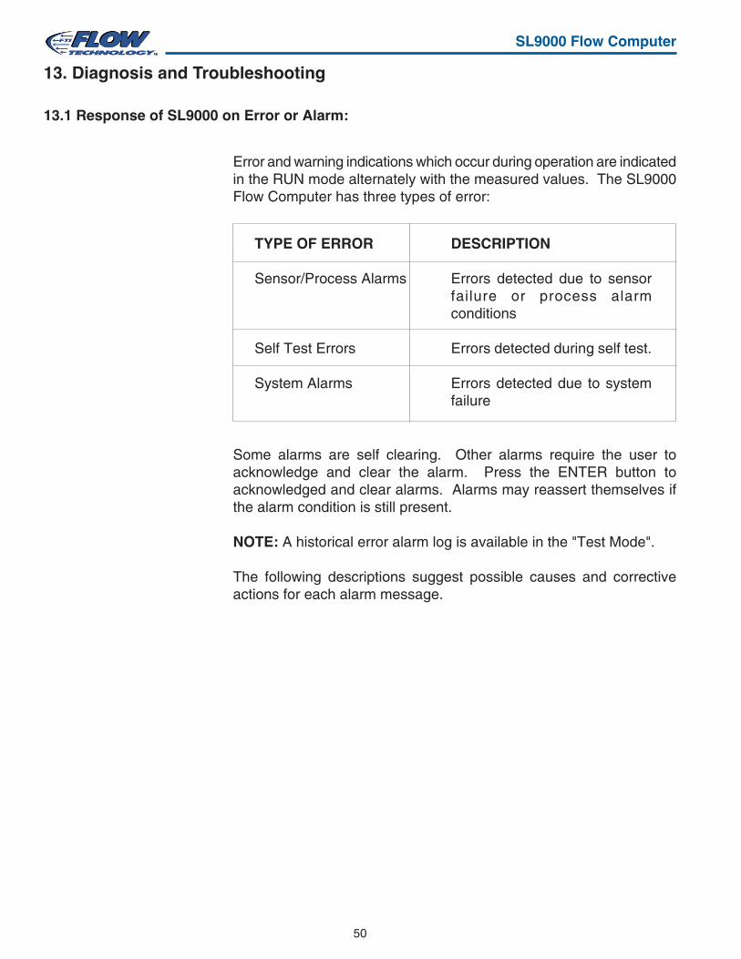
50
SL9000 Flow Computer
13.1 Response of SL9000 on Error or Alarm:
TYPE OF ERROR DESCRIPTION
Sensor/Process Alarms Errors detected due to sensorfailure or process alarmconditions
Self Test Errors Errors detected during self test.
System Alarms Errors detected due to systemfailure
Error and warning indications which occur during operation are indicatedin the RUN mode alternately with the measured values. The SL9000Flow Computer has three types of error:
Some alarms are self clearing. Other alarms require the user toacknowledge and clear the alarm. Press the ENTER button toacknowledged and clear alarms. Alarms may reassert themselves ifthe alarm condition is still present.
NOTE: A historical error alarm log is available in the "Test Mode".
The following descriptions suggest possible causes and correctiveactions for each alarm message.
13. Diagnosis and Troubleshooting
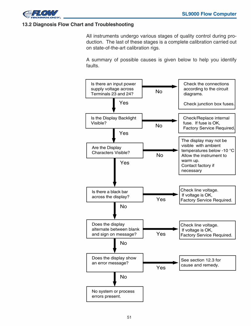
51
SL9000 Flow Computer
13.2 Diagnosis Flow Chart and Troubleshooting
Is there an input power supply voltage across Terminals 23 and 24? No
Yes
Check the connections according to the circuit diagrams.
Check junction box fuses.
Is the Display BacklightVisible?
No
Yes
Check/Replace internal fuse. If fuse is OK, Factory Service Required.
Is there a black bar across the display?
YesNo
Does the display alternate between blank and sign on message? Yes
No
Does the display show an error message?
Yes
No
See section 12.3 for cause and remedy.
No system or process errors present.
Are the Display Characters Visible?
No
Yes
The display may not be visible with ambient temperatures below -10 °CAllow the instrument to warm up.Contact factory if necessary
Check line voltage. If voltage is OK,Factory Service Required.
Check line voltage. If voltage is OK,Factory Service Required.
All instruments undergo various stages of quality control during pro-duction. The last of these stages is a complete calibration carried outon state-of-the-art calibration rigs.
A summary of possible causes is given below to help you identifyfaults.
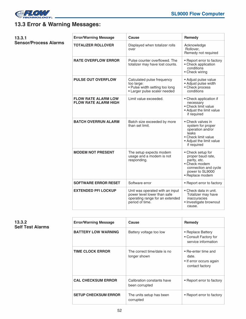
52
SL9000 Flow Computer
Cause
Battery voltage too low
The correct time/date is nolonger shown
Calibration constants havebeen corrupted
The units setup has beencorrupted
Remedy
• Replace Battery• Consult Factory for
service information
• Re-enter time anddate.
• If error occurs againcontact factory
• Report error to factory
• Report error to factory
Error/Warning Message
BATTERY LOW WARNING
TIME CLOCK ERROR
CAL CHECKSUM ERROR
SETUP CHECKSUM ERROR
13.3.2Self Test Alarms
Cause
Displayed when totalizer rollsover
Pulse counter overflowed. Thetotalizer may have lost counts.
Calculated pulse frequencytoo large:• Pulse width setting too long• Larger pulse scaler needed
Limit value exceeded.
Batch size exceeded by morethan set limit.
The setup expects modemusage and a modem is notresponding.
Software error
Unit was operated with an inputpower level lower than safeoperating range for an extendedperiod of time.
Remedy
Acknowledge Rollover,Remedy not required
• Report error to factory• Check application
conditions• Check wiring
• Adjust pulse value• Adjust pulse width• Check process
conditions
• Check application ifnecessary
• Check limit value• Adjust the limit value
if required
• Check valves insystem for properoperation and/orleaks
• Check limit value• Adjust the limit value
if required
• Check setup forproper baud rate,parity, etc.
• Check modemconnection and cyclepower to SL9000
• Replace modem
• Report error to factory
• Check data in unit.Totalizer may haveinaccuracies
• Investigate brownoutcause.
Error/Warning Message
TOTALIZER ROLLOVER
RATE OVERFLOW ERROR
PULSE OUT OVERFLOW
FLOW RATE ALARM LOWFLOW RATE ALARM HIGH
BATCH OVERRUN ALARM
MODEM NOT PRESENT
SOFTWARE ERROR RESET
EXTENDED PFI LOCKUP
13.3.1Sensor/Process Alarms
13.3 Error & Warning Messages:
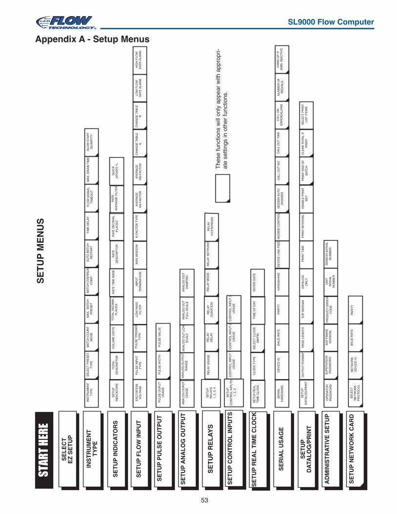
53
SL9000 Flow Computer
SE
TU
P M
EN
US
Appendix A - Setup Menus
SE
TU
PIN
DIC
AT
OR
STO
TAL
DE
SC
RIP
TO
RV
OLU
ME
UN
ITS
TO
TAL
DE
CIM
AL
PLA
CE
S
EX
CIT
AT
ION
VO
LTA
GE
PU
LSE
INP
UT
TY
PE
PU
LSE
TR
IGG
ER
TY
PE
LOW
PA
SS
FIL
TE
R
INS
TR
UM
EN
TT
YP
EB
AT
CH
CO
UN
TM
OD
E
SE
LE
CT
EZ
SE
TU
P
SE
TU
P P
UL
SE
OU
TP
UT
SE
TU
P F
LO
W IN
PU
T
SE
TU
P IN
DIC
ATO
RS
INS
TR
UM
EN
TT
YP
E
SE
TU
PR
ELA
YS
1, 2
, 3, 4
RE
LAY
DU
RA
TIO
NR
ELA
Y U
SA
GE
RE
LAY
DE
LAY
SE
TU
P R
EL
AY
S
STAR
T HE
RE
PU
LSE
OU
PU
TU
SA
GE
PU
LSE
WID
TH
PU
LSE
VA
LUE
AN
ALO
G O
UP
UT
US
AG
EA
NA
LOG
OU
T L
OW
SC
ALE
AN
ALO
G O
UT
FU
LL S
CA
LES
ET
UP
AN
AL
OG
OU
TP
UT
AN
ALO
G O
UT
PU
TR
AN
GE
MA
X.
BA
TC
HP
RE
SE
TS
ELE
CT
PR
ES
ET
TY
PE
RA
TE
TIM
E B
AS
ER
AT
ED
ES
CR
IPT
OR
RA
TE
DE
CIM
AL
PLA
CE
SR
AT
EA
VE
RA
GE
FIL
TE
RQ
UIC
KU
PD
AT
E %
INP
UT
TE
RM
INA
TIO
NM
AX
WIN
DO
WK
-FA
CT
OR
TY
PE
AV
ER
AG
EK
A-F
AC
TO
R
BA
TC
H O
VE
RR
UN
CO
MP.
AU
TO
BA
TC
HR
ES
TAR
TM
AX
. DR
AIN
TIM
E
SE
RIA
LH
AR
DW
AR
ED
EV
ICE
IDB
AU
D R
AT
EP
AR
ITY
HA
ND
SH
AK
ED
EV
ICE
LIN
E F
EE
D
OP
ER
AT
OR
PA
SS
WO
RD
SU
PE
RV
ISO
RP
AS
SW
OR
DS
OF
TW
AR
EV
ER
SIO
NA
DM
INIS
TR
AT
IVE
SE
TU
P
SE
RIA
L U
SA
GE
SLO
W S
TAR
TQ
UA
NT
ITY
PR
OD
UC
T O
RD
ER
CO
DE
UN
ITS
ER
IAL
NU
MB
ER
SE
NS
OR
SE
RIA
LN
UM
BE
R
The
se fu
nctio
ns w
ill o
nly
appe
ar w
ith a
ppro
pri-
ate
setti
ngs
in o
ther
func
tions
.
RE
LAY
SE
TP
OIN
TR
ELA
YH
YS
TE
RE
SIS
RE
LAY
MO
DE
SE
TU
P R
EA
LT
IME
CLO
CK
EN
TE
R D
AT
ES
ELE
CT
CLO
CK
AM
/PM
TIM
E O
F D
AY
SE
TU
P R
EA
L T
IME
CL
OC
K
MO
DE
M C
ON
TR
OL
FLO
W S
IGN
AL
TIM
EO
UT
CA
LL O
NE
RR
OR
/ALA
RM
NU
MB
ER
OF
RE
DIA
LSH
AN
G-U
P IF
2MIN
. IN
AC
TIV
EM
OD
EM
AU
TO
AN
SW
ER
CA
LL O
UT
NO
AV
ER
AG
EK
B-F
AC
TO
RC
HA
NG
E T
AB
LEA
CH
AN
GE
TA
BLE
BLO
W F
LOW
RA
TE
ALA
RM
HIG
H F
LOW
RA
TE
ALA
RM
AN
ALO
G O
UT
DA
MP
ING
CO
NT
RO
L IN
PU
T 1
US
AG
EC
ON
TR
OL
INP
UT
2U
SA
GE
CO
NT
RO
L IN
PU
T 3
US
AG
ES
ET
UP
CO
NT
RO
L IN
PU
TS
SE
TU
PC
ON
TR
OL
INP
UT
S1,
2, 3
CLO
CK
TY
PE
CA
LL O
UT
TIM
E
SE
TU
PD
ATA
LOG
/PR
INT
OU
TP
UT
FO
RM
AT
PA
GE
LE
NG
TH
TO
P M
AR
GIN
CLE
AR
TO
TAL
IFP
RIN
TS
ELE
CT
PR
INT
LIS
T IT
EM
SS
ET
UP
DA
TAL
OG
/PR
INT
DA
TALO
GO
NLY
PR
INT
TIM
EP
RIN
T IN
TE
RV
AL
EN
AB
LE P
RIN
TK
EY
TIM
E D
ELA
Y
PR
INT
EN
D O
FB
AT
CH
SE
LEC
TN
ET
WO
RK
PR
OT
OC
OL
NE
TW
OR
KD
EV
ICE
IDB
AU
D R
AT
EP
AR
ITY
SE
TU
P N
ET
WO
RK
CA
RD
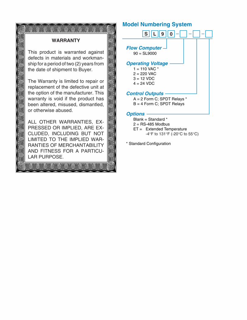
WARRANTY
This product is warranted againstdefects in materials and workman-ship for a period of two (2) years fromthe date of shipment to Buyer.
The Warranty is limited to repair orreplacement of the defective unit atthe option of the manufacturer. Thiswarranty is void if the product hasbeen altered, misused, dismantled,or otherwise abused.
ALL OTHER WARRANTIES, EX-PRESSED OR IMPLIED, ARE EX-CLUDED, INCLUDING BUT NOTLIMITED TO THE IMPLIED WAR-RANTIES OF MERCHANTABILITYAND FITNESS FOR A PARTICU-LAR PURPOSE.
Model Numbering System
S L 9 0
Flow Computer90 = SL9000
Operating Voltage1 = 110 VAC *2 = 220 VAC3 = 12 VDC4 = 24 VDC
Control OutputsA = 2 Form C; SPDT Relays *B = 4 Form C; SPDT Relays
OptionsBlank = Standard *2 = RS-485 ModbusET = Extended Temperature
-4°F to 131°F (-20°C to 55°C)
* Standard Configuration