Embed Size (px)
Citation preview
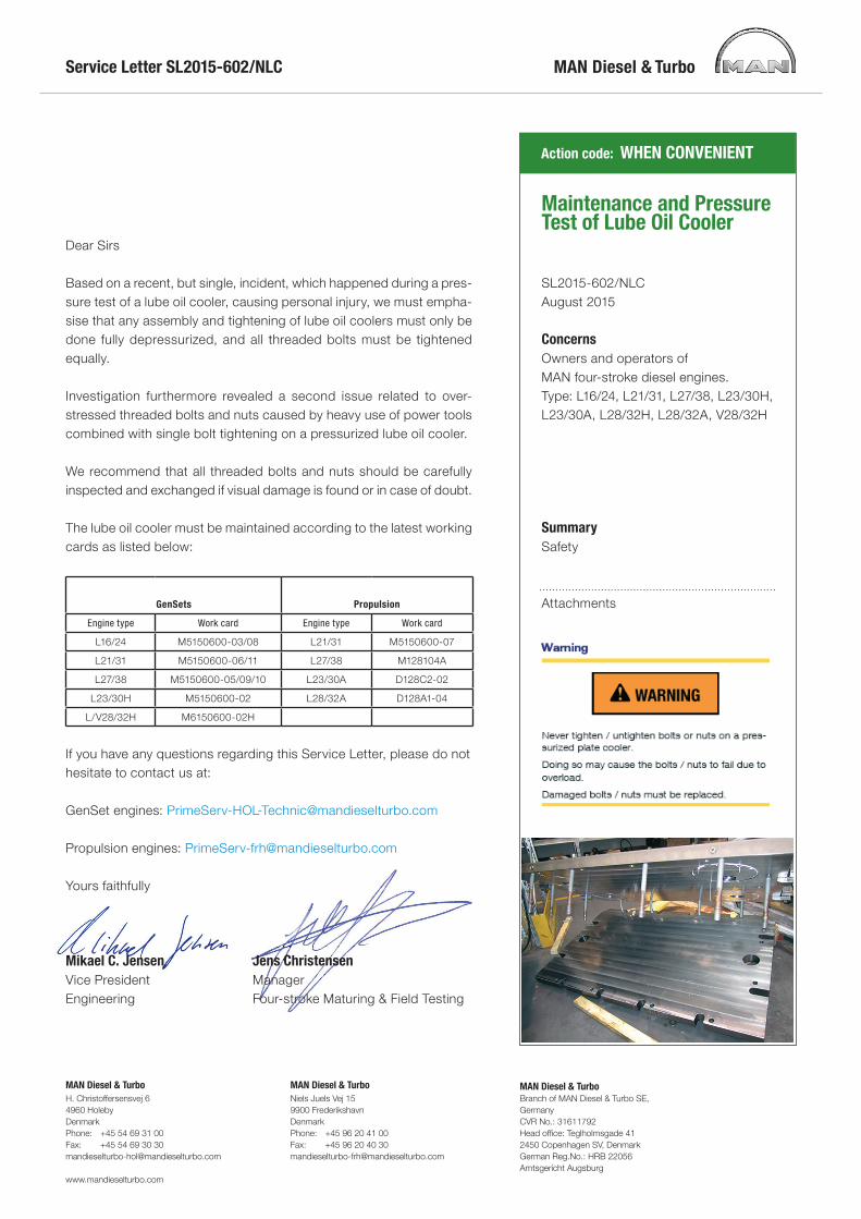
Service Letter SL2015-602/NLC
Action code: WHEN CONVENIENT
MAN Diesel & TurboH. Christoffersensvej 64960 HolebyDenmarkPhone: +45 54 69 31 00Fax: +45 54 69 30 [email protected]
www.mandieselturbo.com
MAN Diesel & TurboNiels Juels Vej 159900 FrederikshavnDenmarkPhone: +45 96 20 41 00Fax: +45 96 20 40 [email protected]
MAN Diesel & TurboBranch of MAN Diesel & Turbo SE, GermanyCVR No.: 31611792Head office: Teglholmsgade 412450 Copenhagen SV, DenmarkGerman Reg.No.: HRB 22056Amtsgericht Augsburg
Dear Sirs
Based on a recent, but single, incident, which happened during a pres-sure test of a lube oil cooler, causing personal injury, we must empha-sise that any assembly and tightening of lube oil coolers must only be done fully depressurized, and all threaded bolts must be tightened equally.
Investigation furthermore revealed a second issue related to over-stressed threaded bolts and nuts caused by heavy use of power tools combined with single bolt tightening on a pressurized lube oil cooler.
We recommend that all threaded bolts and nuts should be carefully inspected and exchanged if visual damage is found or in case of doubt.
The lube oil cooler must be maintained according to the latest workingcards as listed below:
GenSets Propulsion
Engine type Work card Engine type Work card
L16/24 M5150600-03/08 L21/31 M5150600-07
L21/31 M5150600-06/11 L27/38 M128104A
L27/38 M5150600-05/09/10 L23/30A D128C2-02
L23/30H M5150600-02 L28/32A D128A1-04
L/V28/32H M6150600-02H
If you have any questions regarding this Service Letter, please do not hesitate to contact us at:
GenSet engines: [email protected]
Propulsion engines: [email protected]
Yours faithfully
Mikael C. JensenVice PresidentEngineering
Jens ChristensenManagerFour-stroke Maturing & Field Testing
Maintenance and Pressure Test of Lube Oil Cooler
SL2015-602/NLCAugust 2015
ConcernsOwners and operators of MAN four-stroke diesel engines.Type: L16/24, L21/31, L27/38, L23/30H, L23/30A, L28/32H, L28/32A, V28/32H
SummarySafety
Attachments

Safety precautions
Engine stoppedShut-off starting airShut off cooling waterShut off fuel oilShut-off cooling oilStop lub. oil circulationPress Blocking - Reset
Short Description
Separation, cleaning and assembling. Replace-ment of plates and gaskets.
Starting PositionCooling water and lube oil have been drained fromcooler/engine. All external pipes are disconnected.
Related Procedure
Qualified Manpower
Duration in h : 4Number : 1
Data
Data for pressure and tolerance (Page 500.35)Data for tightening torque (Page 500.40)Declaration of weight (Page 500.45)
Special tools
Plate No. Item No. Note52000 032 52002 508 52002 521
Hand ToolsRing and open end spanner, 10 mmRing and open end spanner, 55 mmRing and open end spanner, 30 mmAdjustable spanner
Replacement and wearing parts
Plate No. Item No. Quantity
MAN Diesel & Turbo
Work CardPage 1 (6) Lubricating oil cooler
515-06.00Edition 09
L27/38, L27/38S
2015.03.20 - Tier II, Stationary

Warning
Never tighten / untighten bolts or nuts on a pres-surized plate cooler.
Doing so may cause the bolts / nuts to fail due tooverload.
Damaged bolts / nuts must be replaced.
Introduction
Figure 1: Mounting of oil cooler in front-end boxCleaning of the cooler must take place, when thepressure drop on the oil and water side exceeds anallowable value and/or if oil cannot be sufficientlycooled.
MAN Diesel & Turbo515-06.00Edition 09
Lubricating oil cooler Work CardPage 2 (6)
L27/38, L27/38S
2015.03.20 - Tier II, Stationary

To prevent oil from dripping / flowing on the pre-lubricating pump it is recommended to screenthe pump before the lubricating oil cooler is sep-arated.
Separation
Cooling and pressure relief
Before opening the plate heat exchanger, it must becooled down to below 40° C and be without pres-sure!
The cooling must not exceed 10° C per minute. The pressure drop must not exceed 10 bar perminute.
If these norms are exceeded, the guarantee willcease to be valid.
Separation of edge-clamped frame
Upon completion of the procedure “Cooling andPressure Relief”, separate the frame by retainingtwo or four diagonally placed bolts.
Take care that the pressure plate does not tilt!
Loosen the bolts uniformly and diagonally (max. 10mm at a time), then push the pressure platetowards the end support. When the pressure plateis not tight anymore, the plates can be removed.
When using plate heat exchangers on boardships, the pressure plate have to be secured inorder to avoid danger during the movements ofthe ship.
Cleaning
The capacity and corrosion resistance of the plateheat exchangers depend on the cleanness of theplates. Any coating on the plates can be removedmanually.
Manual cleaning
Clean the plates with a soft brush and a suitabledetergent. In case of dense coating of scale ororganic materials, the plates must be put in a bathwith detergent.
Never use a steel brush, metal scraper or thelike.
A high-pressure cleaner can be used with care,however, never with sand or other abrasives added.
Detergents
A detergent is suitable, if it will removes any coatingon the plates without causing any damage to platesand gaskets.
It is of great importance that decomposition ofthe protective film on the stainless steel does nottake place - the film preserves the corrosionresistance of steel.
Do not use chlorine-containing agents such ashydrochloricacid (HCI)!
MAN Diesel & Turbo
Work CardPage 3 (6) Lubricating oil cooler
515-06.00Edition 09
L27/38, L27/38S
2015.03.20 - Tier II, Stationary

Oil and fats are removed by using a water emulsify-ing oil solvent, e.g. BP-system cleaner.
Organic and greasy coatings are removed by usingsodium hydroxide (NaOH):
▪ max. concentration 1.5% (1.5% concentration corresponds to 3.75 l 30%NaOH per 100 l water).
▪ max. temperature 85° C.
Stone and lime/calcareous deposits are removedby using nitric acid (HNO3):
▪ max. concentration 1.5% (1.5% concentration corresponds to 1.75 l 62%HNO3 per 100 l water).
▪ max. temperature 65° C.
The nitric acid has an important constructiveeffect on the protective film of stainless steel.
Control of cleaning fluid concentrations
Sodium hydroxide (NaOH) solution is tritrated with0.1 n hydro-chloric acid (HCI) with methyl orange ormethyl red as indicator.
Nitric acid (HNO3) solution is titrated with 0.1 nsodium hydroxide (NaOH) with phenolphtalin as anindicator.
The concentration of the cleaning fluid in % can becalculated from the titration result using the follow-ing formula:
a : ml cleaning fluid taken out for titration
b : ml titration fluid used as cover
n : the molecular concentration of titration fluid
m : The molecular weight of the cleaning fluid(NaOH) molecular weight 40, HNO3 molecularweight 63)
Replacement of plates and gaskets
Marking
The plates are marked with material codes and ref-erence numbers at each end, plus codes for non-glued gaskets, if any, and stamped with the letter Vand H at either end (Fig 1).
When facing the gasket, the plate is designated asa left plate, when letter V turns upwards - and as aright plate when letter H turns upwards. Inlets andoutlets of the V-plates are taking place through thecorner holes Nos 1 and 4. Inlets and outlets of theH-plates take place through corner holes Nos 2 and3.
Replacement of plates
Before mounting a spare plate in the plate stack,please make sure that the spare plate is identicalwith the faulty one.
The same corner holes must be opened and let-ters V and H must be placed properly.
Replacement of glued gaskets
On Plate 51506 stated are gasket and glue quan-tity.
Please use a degreasing agent on the new gaskets.
The first plate after the end cover and the connectorgrid must have gaskets in all grooves. The gasketsmust be cut according to the existing gaskets.
Loosen the glued gaskets by heating the plate inwater at 100° C. Clean the plates and remove thecoatings, if any.
Cleaning of new gaskets and plates
New gaskets and gasket grooves of the plates arecleaned with a cloth moistened with degreasingagent. The glue surfaces must be absolutely clean -without finger prints etc.
Please use our cleaning fluid, which conforms tosuppliers recommendations.
Alternatively, please use:
MAN Diesel & Turbo515-06.00Edition 09
Lubricating oil cooler Work CardPage 4 (6)
L27/38, L27/38S
2015.03.20 - Tier II, Stationary

▪ Trichloroethylene
▪ Chlorothene VG
▪ Acetone
▪ Methyl ethyl ketone
▪ Ethylacetat
It is important that all degreasing agent has evapo-rated, before the glue is applied. This will normallytake approx. 15 min. at 20° C.
Clean the new gaskets on the glued surfaces withfine-grained sandpaper instead of the degreasingagent supplied.
Gluing
Pliobond 25, which is a solvent-based nitrile rubberglue (25% solids). The glue is applied with a brushin a thin layer on the backs of the gaskets and thegaskets must be dried in a clean place free of dust.
Apply a thin layer of glue on the gasket grooves ofthe plates and press the gaskets down into the gas-ket grooves.
The insertion of the gaskets starts at both ends ofthe plate - and continues with the straight sectionsalong the edges.
The gluing process is most easily performed byplacing the gaskets and the plates on a table. Afterpressing the gaskets into the grooves of the plate, itis stacked.
The plates with the gaskets are mounted in theframe which is lightly clamped. In the case of usingrubber grooves, they are assembled to the mini-mum measure stated on the engine sign plus 0.2mm per plate.
Heat up the plate heat exchanger to 90-100° C bymeans of water or steam.
Please note
▪ The temperature must be kept for 1½-2 hours.
▪ The liquid pressure must be kept as low as pos-sible.
If there is no possibility of heating the plate heatexchanger, it must be placed in a place as warm aspossible with connections dismounted.
At 20° C the drying time will be approx. 48 hours.At 40° C, the drying time is approx. 24 hours.
Assembling
If the plates are dismounted, they must be properlyassembled according to plate item numbers.
The fixed cover has number 1 and serial numbersfor the subsequent plates, and intermediate frames,if any, are numbered 2, 3, 4, 5 etc.
Figure 2: .
Serial numbers are stamped in the right top cornerof the plates. Further, please note that the gasketside must face the fixed cover.
Figure 3: Measuring x
MAN Diesel & Turbo
Work CardPage 5 (6) Lubricating oil cooler
515-06.00Edition 09
L27/38, L27/38S
2015.03.20 - Tier II, Stationary

Fastening
Fasten the nuts crosswise until the movable coverto the measure x at each nut.
Cyl. x min (mm) x max (mm)
5 66 69
6 66 69
7 66 69
8 85 88
9 97 101
MAN Diesel & Turbo515-06.00Edition 09
Lubricating oil cooler Work CardPage 6 (6)
L27/38, L27/38S
2015.03.20 - Tier II, Stationary

Lubricating oil cooler, overhaul
Warning
Never tighten / untighten bolts or nuts on a pressurized plate cooler.Doing so may cause the bolts / nuts to fail due to overload.Damaged bolts / nuts must be replaced.
Plate 1 2818 - Lubricating oil cooler for engine and reduction gear
DescriptionThe lubricating oil coolers for the engine and reduction gear are a combinedplate heat exchanger. The plates are made of moulded titanium sheet with apattern for optimum heat transfer.
Each plate is fitted with a NBR rubber seal which seals against the adjacentplate.
The whole plate pack is tightened between the connection plate item A5,intermediate plate item A13 and compression plate, item A6.
The heat transfer in a plate heat exchanger is determined by the difference intemperature between the liquids, their velocities and physical characteristics.
Problems during operationA. Sudden rise of lubricating oil temperatureMay be due to blocking of the sea water inlet of the cooler by coarse parti-cles.
B. Decreasing efficiency of the coolerThe lubricating oil temperature rises The heat transfer plates are covered with deposits of sludge, etc and mustbe cleaned as described in the following instruction.
C. Visible leakage on the outside of the plate pack One or more gaskets are defect and must be replaced.
D. Part of one liquid passes over to the other liquid The fault is due to a defective plate which must be replaced.
Overhaul of coolerThe gasket cement tends to soften at high temperatures. A hot cooler musttherefore be cooled to 50°C or less before it is opened.
Dismantling of plate packDismantling must be carried out with care. First remove the two screws, itemAll, the middle one in each end of the thrust plate, item A6.
The screws should be replaced by two long screws, item A15 (included inthe tool set). Now loosen all short screws, item All, in more stages all aroundthe thrust plate. At last loosen the long screws and take away the thrustplate.
2015
-04-
28 -
en
Desc
riptio
nLu
bric
atin
g oi
l coo
ler,
over
haul
D128
C2-0
2-L2
330A
K
MAN Diesel & Turbo D128C2-02-L2330AK
- L23/30A 1 (3)

During dismantling of the heat transfer plates, take care that the gasketsremain in their grooves.
Cleaning of the platesCleaning can be carried out by water flushing and with a fibre brush. A rotat-ing fibre brush can be used with care so the rubber gaskets are not dam-aged. With manual cleaning of the plates a soda solution (carbonate soda) ora solution of water and synthetic detergents may help. After cleaning, theplates should be flushed thoroughly with clean water.
Replacement of rubber gasketsWhen replacing the gaskets on board use contact adhesive (not supplied) ona rubber-base. Replacement of the gaskets is done as follows:
1. The rubber gaskets can normally be removed manually. If this is notpossible - see point 2.
2. Heat the back of the gasket groove carefully with a propane gas orbutane gas burner and pull the gaskets out of the gasket groove.Remaining cement residues are to be removed with a suitable stainlesssteel tool. In difficult cases a rotating steel brush (stainless steel) can beused.
3. Degrease the gasket groove with a suitable detergent.
4. Sort the new gaskets into A and B gaskets according to the drawing.Apply a thin layer of cement to the back of the gaskets. Let the cementdry to non-sticky (10-15 min. at room temperature). Stack gaskets ontop of each other (A and B gaskets separately).
5. Apply a thin line of gasket cement in the gasket groove. Let the cementair dry for a few minutes and lay the pre-glued gasket in the groovewhilst the cement is still sticky. A non—sticky cement layer can be reac-tivated by moistening it with acetone before the gasket is placed in thegroove.
6. Stack plates in the original order. Load the plates with a weight and letthe gasket cement air dry for 3 to 5 hours.
7. Gasket surfaces must be anti-stick treated with silicone oil.
Assembling of the coolerPlate 1 2818 shows the number and order of the plates. The plates must bemounted in the cooler so that the arrow pattern changes direction for eachplate. There is a multi-figure number stamped on each plate with a followingletter A or B. This is the plate’s part number which also indicates whether It isan A plate or a B plate. On the drawing the respective identification numbersare enlarged.
Defect plates can easily be replaced with identical plates. Always make sureto have the correct number of plates so that the plate pack can be tightenedto the correct measurement. If one or some plates are missing, the cooler willleak.
Tightening of the plate packWhen the cooler has been dismantled, check all gaskets and the sealing sur-faces facing the gaskets, i.e. the back of the gasket groove. Particles andimpurities must be removed. Replace damaged gaskets.
Desc
riptio
nLu
bric
atin
g oi
l coo
ler,
over
haul
D128
C2-0
2-L2
330A
K
2015
-04-
28 -
en
D128C2-02-L2330AK MAN Diesel & Turbo
2 (3) - L23/30A

Place the thrust plate, item A6, above the plate pack. Fit the two longassembling screws, item A15, in the middle holes in each end of the thrustplate, and tighten the plate pack together until the short screws, item All, canbe inserted in the thread in the distance pins, item A8.
The screws should be greased with Molycote Paste and tightened equally sothat the plate pack is parallel.
2015
-04-
28 -
en
Desc
riptio
nLu
bric
atin
g oi
l coo
ler,
over
haul
D128
C2-0
2-L2
330A
K
MAN Diesel & Turbo D128C2-02-L2330AK
- L23/30A 3 (3)

Safety precautions
Engine stoppedShut-off starting airShut off cooling waterShut off fuel oilShut-off cooling oilStop lub. oil circulationPress Blocking - Reset
Short Description
Separation, cleaning and assembling. Replace-ment of plates and gaskets.
Starting PositionCooling water and lube oil have been drained fromcooler/engine. All external pipes are disconnected.
Related Procedure
Qualified Manpower
Duration in h : 4Number : 1
Data
Data for pressure and tolerance (Page 500.35)Data for tightening torque (Page 500.40)Declaration of weight (Page 500.45)
Special tools
Plate No. Item No. Note52000 032 52000 044
Hand ToolsRing and open end spanner, 24 mmHexagon key, 6 mm
Replacement and wearing parts
Plate No. Item No. Quantity
MAN Diesel & Turbo
Work CardPage 1 (8) Lubricating Oil Cooler
515-06.00Edition 06
L21/31, L21/31S
2015.03.20

Warning
Never tighten / untighten bolts or nuts on a pres-surized plate cooler.
Doing so may cause the bolts / nuts to fail due tooverload.
Damaged bolts / nuts must be replaced.
Cleaning
1) Clean the plates, see page 6-7.
Opening
1) Drain of water plug E1 and E2, see fig 1.
2) Control of the "x" before disassembly checkwith tabel 1, page 5. Remove nut Nos 3, 4, 5and 6, see fig 3.
3) Loosen the nuts (max 3 turn a time) startingwith No 10 and downwards, see fig 3.
4) Remove the pressure plate.
Figure 1: Drain of water
1 Pressure plate 2 Nut
3 Studs 4 Carrying bar
5 Frame plate 6 Lifting holes
Figure 2: Lub oil cooler
Figure 3: Numbering of bolts
Closing
1) Check that all the sealing surfaces (i.e. surfacesin contact with the heat transfer medium) areclean, see fig 4.
Figure 4: Check of sealing surfaces
2) Check that the ring gaskets, when fitted in con-nections, are in position and are in good condi-tion, see fig 5.
MAN Diesel & Turbo515-06.00Edition 06
Lubricating Oil Cooler Work CardPage 2 (8)
L21/31, L21/31S
2015.03.20

1 Ring gaskets
Figure 5: Ring gaskets
Figure 6: Insertion of plates
3) Regasking if necessary, see page 7.
4) Clean and lubricate the sliding surfaces of thecarrying bar, see fig 2.
5) Mount the plates. Read the plates (see page 6).Plate No 1 close towards engine.
that the gasket side must face the frame plate.The number must be shifted left/right on eachplate.
6) Press the plate assembly together.
7) If the plates are correctly assembled, the edgesform a "honeycomb" pattern, see fig 7.
Figure 7: Correct assembly
8) Lubricate the threads with a thin layer ofgrease.
Tightening of cooler studs
Tightening of the cooler studs is carried out in 3stages to ensure uniform compression and sealingof cooler gaskets.
MAN Diesel & Turbo
Work CardPage 3 (8) Lubricating Oil Cooler
515-06.00Edition 06
L21/31, L21/31S
2015.03.20

Tighten the studs in the sequence shown in fig 8.
Order Bolt No To dimension
1
1-2 and3-4 and5-6 and7-8 and9-10 and 1.10
2 1-10 x
Figure 8: Tighetning of bolts
1) Tightening is carried out alternately and diago-nally 1-2 followed by 3-4 etc. until 1.1x, seetable 1.
2) Tightening is carried out alternately and diago-nally 1-2 followed by 3-4 etc. until 1.05 x, seetable 1.
3) Final tightening is carried out diagonally 1-2 fol-lowed by 3-4 etc. until x, see table 1.
Cyl. x 1,05 x 1,1 x
5 92.0 mm 97 101
6 106.5 mm 112 117
7 127.0 mm 133 140
8 151.0 mm 160 166
9 171.5 mm 180 189
Tolerance + 1 mm
Table 1: .
MAN Diesel & Turbo515-06.00Edition 06
Lubricating Oil Cooler Work CardPage 4 (8)
L21/31, L21/31S
2015.03.20

MAN Diesel & Turbo
Work CardPage 5 (8) Lubricating Oil Cooler
515-06.00Edition 06
L21/31, L21/31S
2015.03.20

Cleaning
Mechanical cleaning after opening
NoteUnder no circumstances should hydrochloric acidbe used with Stainless steel plates.
Water of more than 300 ppm Cl may not be usedfor the preparation of cleaning solutions.
It is very important that carrying bars and supportcolumns i aluminium are protected against chemi-cals.
Biological growth - slime
▪ Bacteria
▪ Nematodes
▪ Protozoa
1) Soft brush and running water.
⇨ Note: Avoid gasket damage.
2) High pressure hose.
Use safety glasses, rubber protection gloves,and protective suit.
3) Chemical cleaning using alkaline cleaningagents:
▪ Sodium hydroxide
▪ Sodium carbonate
▪ Cleaning effect can be considerably increasedby the addition of small quantities of hypochlor-ite or agents for the formation of complexes andsurfactants.
Concentration max 4%
Temperature max 80°C
Incrustation - scaling
▪ Calcium carbonate
▪ Calcium sulphate
▪ Silicates
1) Soft brush and running water.Note Avoid gasket damage.
2) High pressure hose.
3) Chemical cleaning on opened unit by using:
Use safety glasses, rubber protection gloves,and protective suit.
▪ Nitric acid
▪ Sulfamic acid
▪ Citric acid
▪ Phosphoric acid
▪ Complexing agents (EDTA, NTA).
▪ Sodium polyphosphates.
Concentration max 4%
Temperature max 60 °C
MAN Diesel & Turbo515-06.00Edition 06
Lubricating Oil Cooler Work CardPage 6 (8)
L21/31, L21/31S
2015.03.20

Figure 9: Cleaning
Sediment
▪ Corrosion products
▪ Metal oxides
▪ Silt
▪ Alumina
▪ Diatomic organisms and their excrement of vari-ous colours.
1) Soft brush and running water.Note Avoid gasket damage.
2) High pressure hose.
Use safety glasses, rubber protection gloves,and protective suit.
3) Chemical cleaning on opened unit by using:
▪ Nitric acid
▪ Sulfamic acid
▪ Citric acid
▪ Phosphoric acid
▪ Complexing agents (EDTA, NTA).
▪ Sodium polyphosphates.
Concentration max 4%
Temperature max 60°C
Oil residues, asphalt and fats
▪ Oil residues
▪ Asphalt
▪ Fats
1) Hydrocarbon-based deposits may be removedby using a soft brush and a Paraffi nic orNaphta-based solvent (e.g. Kerosine).
⇨ Note Gaskets in natural, butyl and EPDMrubber swell in these media.Contact time should be limited to 0.5 hour.The following solvents should not be used:
▪ Ketones (e.g. Acetone, Methyletylketone, Meth-ylisobutylketone)
▪ Esters (e.g. Ethylacetate, Butylacetate)
▪ Halogenated hydrocarbons (e.g. Chlorothene,Carbon tetrachloride, Freons)
▪ Aromatics (e.g. Benzene, Toluene)
2) Dry with a cloth or rinse with water.
Regasketing
The Clip-on gasket is attached to the plate by twogasket prongs which slip under the edge of theplate to hold the gasket securely in alignment in thegasket groove.
The prongs are situated at regular intervals aroundthe periphery of the plate.
When the plate heat exchanger is then assembledand tightened, the gasket provides a tight sealaround the plate.
MAN Diesel & Turbo
Work CardPage 7 (8) Lubricating Oil Cooler
515-06.00Edition 06
L21/31, L21/31S
2015.03.20

Figure 10: Regasketing
MAN Diesel & Turbo515-06.00Edition 06
Lubricating Oil Cooler Work CardPage 8 (8)
L21/31, L21/31S
2015.03.20

Safety precautions
Engine stoppedShut-off starting airShut off cooling waterShut off fuel oilShut-off cooling oilStop lub. oil circulationPress Blocking - Reset
Short Description
Separation, cleaning and assembling. Replace-ment of plates and gaskets.
Starting PositionCooling water and lube oil have been drained fromcooler/engine. All external pipes are disconnected.
Related Procedure
Qualified Manpower
Duration in h : 4Number : 1
Data
Data for pressure and tolerance (Page 500.35)Data for tightening torque (Page 500.40)Declaration of weight (Page 500.45)
Special tools
Plate No. Item No. Note
Hand ToolsRing and open end spanner, 10 mmRing and open end spanner, 55 mmRing and open end spanner, 30 mmAdjustable spanner
Replacement and wearing parts
Plate No. Item No. Quantity
51506 111/279 4/cooler
MAN Diesel & Turbo
Work CardPage 1 (5) Lubricating oil cooler
515-06.00Edition 02
L23/30H, L23/30S
2015.03.20

Warning
Never tighten / untighten bolts or nuts on a pres-surized plate cooler.
Doing so may cause the bolts / nuts to fail due tooverload.
Damaged bolts / nuts must be replaced.
Introduction
Cleaning of the cooler must take place, when thepressure drop on the oil and water side exceeds anallowable value and/or if oil cannot be sufficientlycooled.
Separation
Cooling and pressure relief
Before opening the plate heat exchanger, it must becooled down to below 40° C and be without pres-sure!
The cooling must not exceed 10° C per minute. The pressure drop must not exceed 10 bar perminute.
If these norms are exceeded, the guarantee willcease to be valid.
Separation of edge-clamped frame
Upon completion of the procedure “Cooling andPressure Relief”, separate the frame by retainingtwo or four diagonally placed bolts.
Take care that the pressure plate does not tilt!
Loosen the bolts uniformly and diagonally (max. 10mm at a time), then push the pressure platetowards the end support. When the pressure plateis not tight anymore, the plates can be removed.
When using plate heat exchangers on boardships, the pressure plate have to be secured inorder to avoid danger during the movements ofthe ship.
Cleaning
The capacity and corrosion resistance of the plateheat exchangers depend on the cleanness of theplates. Any coating on the plates can be removedmanually.
Manual cleaning
Clean the plates with a soft brush and a suitabledetergent. In case of dense coating of scale ororganic materials, the plates must be put in a bathwith detergent.
Never use a steel brush, metal scraper or thelike.
A high-pressure cleaner can be used with care,however, never with sand or other abrasives added.
MAN Diesel & Turbo515-06.00Edition 02
Lubricating oil cooler Work CardPage 2 (5)
L23/30H, L23/30S
2015.03.20

Detergents
A detergent is suitable, if it will removes any coatingon the plates without causing any damage to platesand gaskets.
It is of great importance that decomposition ofthe protective film on the stainless steel does nottake place - the film preserves the corrosionresistance of steel.
Do not use chlorine-containing agents such ashydrochloricacid (HCI)!
Oil and fats are removed by using a water emulsify-ing oil solvent, e.g. BP-system cleaner.
Organic and greasy coatings are removed by usingsodium hydroxide (NaOH):
▪ max. concentration 1.5% (1.5% concentration corresponds to 3.75 l 30%NaOH per 100 l water).
▪ max. temperature 85° C.
Stone and lime/calcareous deposits are removedby using nitric acid (HNO3):
▪ max. concentration 1.5% (1.5% concentration corresponds to 1.75 l 62%HNO3 per 100 l water).
▪ max. temperature 65° C.
The nitric acid has an important constructiveeffect on the protective film of stainless steel.
Control of cleaning fluid concentrations
Sodium hydroxide (NaOH) solution is tritrated with0.1 n hydro-chloric acid (HCI) with methyl orange ormethyl red as indicator.
Nitric acid (HNO3) solution is titrated with 0.1 nsodium hydroxide (NaOH) with phenolphtalin as anindicator.
The concentration of the cleaning fluid in % can becalculated from the titration result using the follow-ing formula:
a : ml cleaning fluid taken out for titration
b : ml titration fluid used as cover
n : the molecular concentration of titration fluid
m : The molecular weight of the cleaning fluid(NaOH) molecular weight 40, HNO3 molecularweight 63)
Replacement of plates and gaskets
Marking
The plates are marked with material codes and ref-erence numbers at each end, plus codes for non-glued gaskets, if any, and stamped with the letter Vand H at either end (Fig 1).
When facing the gasket, the plate is designated asa left plate, when letter V turns upwards - and as aright plate when letter H turns upwards. Inlets andoutlets of the V-plates are taking place through thecorner holes Nos 1 and 4. Inlets and outlets of theH-plates take place through corner holes Nos 2 and3.
Replacement of plates
Before mounting a spare plate in the plate stack,please make sure that the spare plate is identicalwith the faulty one.
The same corner holes must be opened and let-ters V and H must be placed properly.
Replacement of glued gaskets
On Plate 51506 stated are gasket and glue quan-tity.
Please use a degreasing agent on the new gaskets.
MAN Diesel & Turbo
Work CardPage 3 (5) Lubricating oil cooler
515-06.00Edition 02
L23/30H, L23/30S
2015.03.20

The first plate after the end cover and the connectorgrid must have gaskets in all grooves. The gasketsmust be cut according to the existing gaskets.
Loosen the glued gaskets by heating the plate inwater at 100° C. Clean the plates and remove thecoatings, if any.
Cleaning of new gaskets and plates
New gaskets and gasket grooves of the plates arecleaned with a cloth moistened with degreasingagent. The glue surfaces must be absolutely clean -without finger prints etc.
Please use our cleaning fluid, which conforms tosuppliers recommendations.
Alternatively, please use:
▪ Trichloroethylene
▪ Chlorothene VG
▪ Acetone
▪ Methyl ethyl ketone
▪ Ethylacetat
It is important that all degreasing agent has evapo-rated, before the glue is applied. This will normallytake approx. 15 min. at 20° C.
Clean the new gaskets on the glued surfaces withfine-grained sandpaper instead of the degreasingagent supplied.
Gluing
Pliobond 25, which is a solvent-based nitrile rubberglue (25% solids). The glue is applied with a brushin a thin layer on the backs of the gaskets and thegaskets must be dried in a clean place free of dust.
Apply a thin layer of glue on the gasket grooves ofthe plates and press the gaskets down into the gas-ket grooves.
The insertion of the gaskets starts at both ends ofthe plate - and continues with the straight sectionsalong the edges.
The gluing process is most easily performed byplacing the gaskets and the plates on a table. Afterpressing the gaskets into the grooves of the plate, itis stacked.
The plates with the gaskets are mounted in theframe which is lightly clamped. In the case of usingrubber grooves, they are assembled to the mini-mum measure stated on the engine sign plus 0.2mm per plate.
Heat up the plate heat exchanger to 90-100° C bymeans of water or steam.
Please note
▪ The temperature must be kept for 1½-2 hours.
▪ The liquid pressure must be kept as low as pos-sible.
If there is no possibility of heating the plate heatexchanger, it must be placed in a place as warm aspossible with connections dismounted.
At 20° C the drying time will be approx. 48 hours.At 40° C, the drying time is approx. 24 hours.
Assembling
If the plates are dismounted, they must be properlyassembled according to plate item numbers.
The fixed cover has number 1 and serial numbersfor the subsequent plates, and intermediate frames,if any, are numbered 2, 3, 4, 5 etc.
Serial numbers are stamped in the right top cornerof the plates. Further, please note that the gasketside must face the fixed cover.
Figure 1: .
MAN Diesel & Turbo515-06.00Edition 02
Lubricating oil cooler Work CardPage 4 (5)
L23/30H, L23/30S
2015.03.20

Fastening
Fasten the plate heat exchanger until the movablecover touches the duct spacers.
MAN Diesel & Turbo
Work CardPage 5 (5) Lubricating oil cooler
515-06.00Edition 02
L23/30H, L23/30S
2015.03.20

Safety precautions
Engine stoppedShut-off starting airShut off cooling waterShut off fuel oilShut-off cooling oilStop lub. oil circulationPress Blocking - Reset
Short Description
Separation, cleaning and assembling. Replace-ment of plates and gaskets.
Starting PositionCooling water and lube oil have been drained fromcooler/engine. All external pipes are disconnected.
Related Procedure
Qualified Manpower
Duration in h : 4Number : 1
Data
Data for pressure and tolerance (Page 500.35)Data for tightening torque (Page 500.40)Declaration of weight (Page 500.45)
Special tools
Plate No. Item No. Note52000 036
Hand ToolsRing and open end spanner, 24 mmHexagon key, 6 mm
Replacement and wearing parts
Plate No. Item No. Quantity
MAN Diesel & Turbo
Work CardPage 1 (8) Lubricating oil cooler
515-06.00Edition 11
L21/31, L21/31S
2015.03.20 - Tier II, Stationary

Warning
Never tighten / untighten bolts or nuts on a pres-surized plate cooler.
Doing so may cause the bolts / nuts to fail due tooverload.
Damaged bolts / nuts must be replaced.
Cleaning
1) Clean the plates, see page 6-7.
Opening
2) Drain of water plug E1 and E2, see fig 1.
3) Control of the "x" before disassembly checkwith tabel, page 5. Remove nut Nos 3, 4, 5and 6, see fig 3.
4) Loosen the nuts (max 3 turn a time) startingwith No 10 and downwards, see fig 3.
5) Remove the pressure plate.
Figure 1: Drain of water
1 Pressure plate 2 Nut
3 Studs 4 Carrying bar
5 Frame plate 6 Lifting holes
Figure 2: Lub oil cooler
Figure 3: Numbering of bolts
Closing
6) Check that all the sealing surfaces (i.e. surfacesin contact with the heat transfer medium) areclean, see fig 4.
Figure 4: Check of sealing surfaces
7) Check that the ring gaskets, when fitted in con-nections, are in position and are in good condi-tion, see fig 5.
MAN Diesel & Turbo515-06.00Edition 11
Lubricating oil cooler Work CardPage 2 (8)
L21/31, L21/31S
2015.03.20 - Tier II, Stationary

1 Ring gaskets
Figure 5: Ring gaskets
Figure 6: Insertion of plates
8) Regasking if necessary, see page 8.
9) Clean and lubricate the sliding surfaces of thecarrying bar, see fig 2.
10) Mount the plates. Read the plates (see page 6).Plate No 1 close towards engine.
that the gasket side must face the frame plate.The number must be shifted left/right on eachplate.
11) Press the plate assembly together.
12) If the plates are correctly assembled, the edgesform a "honeycomb" pattern, see fig 7.
Figure 7: Correct assembly
13) Lubricate the threads with a thin layer ofgrease.
Tightening of cooler studs
Tightening of the cooler studs is carried out in 3stages to ensure uniform compression and sealingof cooler gaskets.
MAN Diesel & Turbo
Work CardPage 3 (8) Lubricating oil cooler
515-06.00Edition 11
L21/31, L21/31S
2015.03.20 - Tier II, Stationary

Tighten the studs in the sequence shown in fig 8.
Order Bolt No To dimension
1
1-2 and3-4 and5-6 and7-8 and9-10 and 1.10
2 1-10 x
Figure 8: Tighetning of bolts
14) Tightening is carried out alternately and diago-nally 1-2 followed by 3-4 etc. until 1.1x, seetable 1.
15) Tightening is carried out alternately and diago-nally 1-2 followed by 3-4 etc. until 1.05 x, seetable 1.
16) Final tightening is carried out diagonally 1-2 fol-lowed by 3-4 etc. until x, see table 1.
Cyl. x 1,05 x 1,1 x
5 92.0 mm 97 101
6 106.5 mm 112 117
7 127.0 mm 133 140
8 151.0 mm 160 166
9 171.5 mm 180 189
Tolerance + 1 mm
Table 1: .
MAN Diesel & Turbo515-06.00Edition 11
Lubricating oil cooler Work CardPage 4 (8)
L21/31, L21/31S
2015.03.20 - Tier II, Stationary

MAN Diesel & Turbo
Work CardPage 5 (8) Lubricating oil cooler
515-06.00Edition 11
L21/31, L21/31S
2015.03.20 - Tier II, Stationary

Cleaning
Mechanical cleaning after opening
Under no circumstances should hydrochloricacid be used with stainless steel plates
Water of more than 300 ppm Cl may not beused for the preparation of cleaning solutions.
It is very important that carrying bars and sup-port columns i aluminium are protected againstchemicals.
Biological growth - slime
▪ Bacteria
▪ Nematodes
▪ Protozoa
17) Soft brush and running water.
Avoid gasket damage.
18) High pressure hose
Use safety glasses, rubber protection gloves,and protective suit.
19) Chemical cleaning using alkaline cleaningagents:
▪ Sodium hydroxide
▪ Sodium carbonate
▪ Cleaning effect can be considerably increasedby the addition of small quantities of hypochlor-ite or agents for the formation of complexes andsurfactants.
Concentration max 4%
Temperature max 80°C
Incrustation - scaling
▪ Calcium carbonate
▪ Calcium sulphate
▪ Silicates
20) Soft brush and running water.
Avoid gasket damage.
21) High pressure hose.
22) Chemical cleaning on opened unit by using:
Use safety glasses, rubber protection gloves,and protective suit.
▪ Nitric acid
▪ Sulfamic acid
▪ Citric acid
▪ Phosphoric acid
▪ Complexing agents (EDTA, NTA)
▪ Sodium polyphosphates
Concentration max 4%
Temperature max 60 °C
MAN Diesel & Turbo515-06.00Edition 11
Lubricating oil cooler Work CardPage 6 (8)
L21/31, L21/31S
2015.03.20 - Tier II, Stationary

Figure 9: Cleaning
Sediment
▪ Corrosion products
▪ Metal oxides
▪ Silt
▪ Alumina
▪ Diatomic organisms and their excrement of vari-ous colours.
23) Soft brush and running water.
Avoid gasket damage
24) High pressure hose.
Use safety glasses, rubber protection gloves,and protective suit.
25) Chemical cleaning on opened unit by using:
▪ Nitric acid
▪ Sulfamic acid
▪ Citric acid
▪ Phosphoric acid
▪ Complexing agents (EDTA, NTA).
▪ Sodium polyphosphates.
Concentration max 4%
Temperature max 60°C
Oil residues, asphalt and fats
▪ Oil residues
▪ Asphalt
▪ Fats
26) Hydrocarbon-based deposits may be removedby using a soft brush and a Paraffinic orNaphta-based solvent (e.g. Kerosine).
Gaskets in natural, butyl and EPDM rubber swellin these media.
Contact time should be limited to 0.5 hour.The following solvents should not be used:
▪ Ketones (e.g. Acetone, Methyletylketone, Meth-ylisobutylketone)
▪ Esters (e.g. Ethylacetate, Butylacetate)
▪ Halogenated hydrocarbons (e.g. Chlorothene,Carbon tetrachloride, Freons)
▪ Aromatics (e.g. Benzene, Toluene)
27) Dry with a cloth or rinse with water.
MAN Diesel & Turbo
Work CardPage 7 (8) Lubricating oil cooler
515-06.00Edition 11
L21/31, L21/31S
2015.03.20 - Tier II, Stationary

Regasketing
The Clip-on gasket is attached to the plate by twogasket prongs which slip under the edge of theplate to hold the gasket securely in alignment in thegasket groove.
The prongs are situated at regular intervals aroundthe periphery of the plate.
When the plate heat exchanger is then assembledand tightened, the gasket provides a tight sealaround the plate.
Figure 10: Regasketing
MAN Diesel & Turbo515-06.00Edition 11
Lubricating oil cooler Work CardPage 8 (8)
L21/31, L21/31S
2015.03.20 - Tier II, Stationary

Safety precautions
Engine stoppedShut-off starting airShut off cooling waterShut off fuel oilShut-off cooling oilStop lub. oil circulationPress Blocking - Reset
Short Description
Separation, cleaning and assembling. Replace-ment of plates and gaskets.
Starting PositionCooling water and lube oil have been drained fromcooler/engine. All external pipes are disconnected.
Related Procedure
Qualified Manpower
Duration in h : 4Number : 1
Data
Data for pressure and tolerance (Page 500.35)Data for tightening torque (Page 500.40)Declaration of weight (Page 500.45)
Special tools
Plate No. Item No. Note52000 012 52000 032 52000 044
Hand ToolsRing and open end spanner, 10 mmRing and open end spanner, 55 mmRing and open end spanner, 30 mmAdjustable spanner
Replacement and wearing parts
Plate No. Item No. Quantity
MAN Diesel & Turbo
Work CardPage 1 (6) Lubricating oil cooler
515-06.00Edition 05
L27/38
2015.03.20 - Tier I

Warning
Never tighten / untighten bolts or nuts on a pres-surized plate cooler.
Doing so may cause the bolts / nuts to fail due tooverload.
Damaged bolts / nuts must be replaced.
Introduction
Figure 1: Mounting of oil cooler in front-end boxCleaning of the cooler must take place, when thepressure drop on the oil and water side exceeds anallowable value and/or if oil cannot be sufficientlycooled.
MAN Diesel & Turbo515-06.00Edition 05
Lubricating oil cooler Work CardPage 2 (6)
L27/38
2015.03.20 - Tier I

To prevent oil from dripping / flowing on the pre-lubricating pump it is recommended to screenthe pump before the lubricating oil cooler is sep-arated.
Separation
Cooling and pressure relief
Before opening the plate heat exchanger, it must becooled down to below 40° C and be without pres-sure!
The cooling must not exceed 10° C per minute. The pressure drop must not exceed 10 bar perminute.
If these norms are exceeded, the guarantee willcease to be valid.
Separation of edge-clamped frame
Upon completion of the procedure “Cooling andPressure Relief”, separate the frame by retainingtwo or four diagonally placed bolts.
Take care that the pressure plate does not tilt!
Loosen the bolts uniformly and diagonally (max. 10mm at a time), then push the pressure platetowards the end support. When the pressure plateis not tight anymore, the plates can be removed.
When using plate heat exchangers on boardships, the pressure plate have to be secured inorder to avoid danger during the movements ofthe ship.
Cleaning
The capacity and corrosion resistance of the plateheat exchangers depend on the cleanness of theplates. Any coating on the plates can be removedmanually.
Manual cleaning
Clean the plates with a soft brush and a suitabledetergent. In case of dense coating of scale ororganic materials, the plates must be put in a bathwith detergent.
Never use a steel brush, metal scraper or thelike.
A high-pressure cleaner can be used with care,however, never with sand or other abrasives added.
Detergents
A detergent is suitable, if it will removes any coatingon the plates without causing any damage to platesand gaskets.
It is of great importance that decomposition ofthe protective film on the stainless steel does nottake place - the film preserves the corrosionresistance of steel.
Do not use chlorine-containing agents such ashydrochloricacid (HCI)!
MAN Diesel & Turbo
Work CardPage 3 (6) Lubricating oil cooler
515-06.00Edition 05
L27/38
2015.03.20 - Tier I

Oil and fats are removed by using a water emulsify-ing oil solvent, e.g. BP-system cleaner.
Organic and greasy coatings are removed by usingsodium hydroxide (NaOH):
▪ max. concentration 1.5% (1.5% concentration corresponds to 3.75 l 30%NaOH per 100 l water).
▪ max. temperature 85° C.
Stone and lime/calcareous deposits are removedby using nitric acid (HNO3):
▪ max. concentration 1.5% (1.5% concentration corresponds to 1.75 l 62%HNO3 per 100 l water).
▪ max. temperature 65° C.
The nitric acid has an important constructiveeffect on the protective film of stainless steel.
Control of cleaning fluid concentrations
Sodium hydroxide (NaOH) solution is tritrated with0.1 n hydro-chloric acid (HCI) with methyl orange ormethyl red as indicator.
Nitric acid (HNO3) solution is titrated with 0.1 nsodium hydroxide (NaOH) with phenolphtalin as anindicator.
The concentration of the cleaning fluid in % can becalculated from the titration result using the follow-ing formula:
a : ml cleaning fluid taken out for titration
b : ml titration fluid used as cover
n : the molecular concentration of titration fluid
m : The molecular weight of the cleaning fluid(NaOH) molecular weight 40, HNO3 molecularweight 63)
Replacement of plates and gaskets
Marking
The plates are marked with material codes and ref-erence numbers at each end, plus codes for non-glued gaskets, if any, and stamped with the letter Vand H at either end (Fig 1).
When facing the gasket, the plate is designated asa left plate, when letter V turns upwards - and as aright plate when letter H turns upwards. Inlets andoutlets of the V-plates are taking place through thecorner holes Nos 1 and 4. Inlets and outlets of theH-plates take place through corner holes Nos 2 and3.
Replacement of plates
Before mounting a spare plate in the plate stack,please make sure that the spare plate is identicalwith the faulty one.
The same corner holes must be opened and let-ters V and H must be placed properly.
Replacement of glued gaskets
On Plate 51506 stated are gasket and glue quan-tity.
Please use a degreasing agent on the new gaskets.
The first plate after the end cover and the connectorgrid must have gaskets in all grooves. The gasketsmust be cut according to the existing gaskets.
Loosen the glued gaskets by heating the plate inwater at 100° C. Clean the plates and remove thecoatings, if any.
Cleaning of new gaskets and plates
New gaskets and gasket grooves of the plates arecleaned with a cloth moistened with degreasingagent. The glue surfaces must be absolutely clean -without finger prints etc.
Please use our cleaning fluid, which conforms tosuppliers recommendations.
Alternatively, please use:
MAN Diesel & Turbo515-06.00Edition 05
Lubricating oil cooler Work CardPage 4 (6)
L27/38
2015.03.20 - Tier I

▪ Trichloroethylene
▪ Chlorothene VG
▪ Acetone
▪ Methyl ethyl ketone
▪ Ethylacetat
It is important that all degreasing agent has evapo-rated, before the glue is applied. This will normallytake approx. 15 min. at 20° C.
Clean the new gaskets on the glued surfaces withfine-grained sandpaper instead of the degreasingagent supplied.
Gluing
Pliobond 25, which is a solvent-based nitrile rubberglue (25% solids). The glue is applied with a brushin a thin layer on the backs of the gaskets and thegaskets must be dried in a clean place free of dust.
Apply a thin layer of glue on the gasket grooves ofthe plates and press the gaskets down into the gas-ket grooves.
The insertion of the gaskets starts at both ends ofthe plate - and continues with the straight sectionsalong the edges.
The gluing process is most easily performed byplacing the gaskets and the plates on a table. Afterpressing the gaskets into the grooves of the plate, itis stacked.
The plates with the gaskets are mounted in theframe which is lightly clamped. In the case of usingrubber grooves, they are assembled to the mini-mum measure stated on the engine sign plus 0.2mm per plate.
Heat up the plate heat exchanger to 90-100° C bymeans of water or steam.
Please note
▪ The temperature must be kept for 1½-2 hours.
▪ The liquid pressure must be kept as low as pos-sible.
If there is no possibility of heating the plate heatexchanger, it must be placed in a place as warm aspossible with connections dismounted.
At 20° C the drying time will be approx. 48 hours.At 40° C, the drying time is approx. 24 hours.
Assembling
If the plates are dismounted, they must be properlyassembled according to plate item numbers.
The fixed cover has number 1 and serial numbersfor the subsequent plates, and intermediate frames,if any, are numbered 2, 3, 4, 5 etc.
Figure 2: .
Serial numbers are stamped in the right top cornerof the plates. Further, please note that the gasketside must face the fixed cover.
Figure 3: Measuring x
MAN Diesel & Turbo
Work CardPage 5 (6) Lubricating oil cooler
515-06.00Edition 05
L27/38
2015.03.20 - Tier I

Fastening
Fasten the nuts crosswise until the movable coverto the measure x at each nut.
Cyl. x mm
5 66
6 72
7 72
8 81
9 88
MAN Diesel & Turbo515-06.00Edition 05
Lubricating oil cooler Work CardPage 6 (6)
L27/38
2015.03.20 - Tier I

Overhaul of lubricating oil cooler
Safety precautions▪ Shut-off starting air
▪ Stop lub. oil circulation
▪ Select local control
▪ Engine stopped
▪ Shut off cooling water
Manpower
Number Qualification Duration in h
1 4
Special tools
Plate No. Item No. Note
Data
Designation Information
Weights of main compo-nents
Replacement and wearing parts
Plate No. Item No. Quantity
1 2818
Starting PositionCooling water and lub oil have been drained from cooler/engine. All externalpipes are disconnected.
Warning
Never tighten / untighten bolts or nuts on a pressurized plate cooler.Doing so may cause the bolts / nuts to fail due to overload.Damaged bolts / nuts must be replaced.
ProcedureA plate cooler is placed on top of the front-end box and secured by allenscrews. See fig 1.
2015
-04-
28 -
en
Wor
k Ca
rdOv
erha
ul o
f lub
ricat
ing
oil c
oole
rM
1281
04A-
01
MAN Diesel & Turbo M128104A-01
- L27/38 1 (4)

Figure 1: Cooler mounted on front-end box
Inlet and outlet of water and oil are sealed with O-rings between the bottomplate of the cooler and the front-end box. The cooler plates are made ofstainless steel and the gaskets are of the clip-on type.
Whenever it becomes necessary to clean the cooler, this can take place intwo different ways:
1. The complete cooler can be removed from the engine and brought to awork shop for overhaul.
2. The cooler can be dismantled on the engine.
Disassembling of the cooler
Figure 2: Oil cooler
This cooler (see fig 2) has long assembling studs and does not need specialtools for disassembling or assembling. In addition, it has tubes around thestuds against which the top frame plate has to be tightened to ensure theright compression of the plates.
Wor
k Ca
rdOv
erha
ul o
f lub
ricat
ing
oil c
oole
rM
1281
04A-
01
2015
-04-
28 -
en
M128104A-01 MAN Diesel & Turbo
2 (4) - L27/38

Cleaning agentKerosene on the oil side. Citric acid on the water side, or agents that do notharm the stainless steel or the nitrile rubber gasket.
After cleaning, the condition of the gaskets is to be checked.
Replace gaskets with cracks or other types of damage.
Replacement of clip-on gasket, see fig 3.
Figure 3: The clip-on gasket in the gasket groove
Assembling of the cooler, fig 41. Place the first cooler plate marked 367317-0483A with the gasket
against the bottom frame plate.
2. The plates marked 367317-4403 are placed one by one on the forego-ing plate and always with the canal pattern pointing in the oppositedirection of the foregoing.
3. Place the final plate marked 367317- 0476 A.
4. Place the top frame plate on top of the cooler plates.
5. Tighten the nuts crosswise in turns and only a little at the time to ensurethat the top frame plate comes down in parallel with the bottom frameplate.
2015
-04-
28 -
en
Wor
k Ca
rdOv
erha
ul o
f lub
ricat
ing
oil c
oole
rM
1281
04A-
01
MAN Diesel & Turbo M128104A-01
- L27/38 3 (4)

Figure 4: Lubricating oil cooler – viewed from below
Wor
k Ca
rdOv
erha
ul o
f lub
ricat
ing
oil c
oole
rM
1281
04A-
01
2015
-04-
28 -
en
M128104A-01 MAN Diesel & Turbo
4 (4) - L27/38

Safety precautions
Engine stoppedShut-off starting airShut off cooling waterShut off fuel oilShut-off cooling oilStop lub. oil circulationPress Blocking - Reset
Short Description
Separation, cleaning and assembling. Replace-ment of plates and gaskets.
Starting PositionCooling water and lube oil have been drained fromcooler/engine. All external pipes are disconnected.
Related Procedure
Qualified Manpower
Duration in h : 4Number : 1
Data
Data for pressure and tolerance (600.35)Data for tightening torque (600.40)Declaration of weight (600.45)
Special tools
Plate No. Item No. Note
Hand ToolsRing and open end spanner, 10 mmRing and open end spanner, 55 mmRing and open end spanner, 30 mmAdjustable spanner
Replacement and wearing parts
Plate No. Item No. Quantity
61506 09 4/cooler
MAN Diesel & Turbo
Work CardPage 1 (5) Lubricating oil cooler
615-06.00Edition 02H
L28/32H, V28/32H
2015.03.20

Warning
Never tighten / untighten bolts or nuts on a pres-surized plate cooler.
Doing so may cause the bolts / nuts to fail due tooverload.
Damaged bolts / nuts must be replaced.
Introduction
Cleaning of the cooler must take place, when thepressure drop on the oil and water side exceeds anallowable value and/or if oil cannot be sufficientlycooled.
Separation
Cooling and pressure relief
Before opening the plate heat exchanger, it must becooled down to below 40° C and be without pres-sure!
The cooling must not exceed 10° C per minute. The pressure drop must not exceed 10 bar perminute.
If these norms are exceeded, the guarantee willcease to be valid.
Separation of edge-clamped frame
Upon completion of the procedure “Cooling andPressure Relief”, separate the frame by retainingtwo or four diagonally placed bolts.
Take care that the pressure plate does not tilt!
Loosen the bolts uniformly and diagonally (max. 10mm at a time), then push the pressure platetowards the end support. When the pressure plateis not tight anymore, the plates can be removed.
When using plate heat exchangers on boardships, the pressure plate have to be secured inorder to avoid danger during the movements ofthe ship.
Cleaning
The capacity and corrosion resistance of the plateheat exchangers depend on the cleanness of theplates. Any coating on the plates can be removedmanually.
Manual cleaning
Clean the plates with a soft brush and a suitabledetergent. In case of dense coating of scale ororganic materials, the plates must be put in a bathwith detergent.
Never use a steel brush, metal scraper or thelike.
A high-pressure cleaner can be used with care,however, never with sand or other abrasives added.
MAN Diesel & Turbo615-06.00
Edition 02HLubricating oil cooler Work Card
Page 2 (5)
L28/32H, V28/32H
2015.03.20

Detergents
A detergent is suitable, if it will removes any coatingon the plates without causing any damage to platesand gaskets.
It is of great importance that decomposition ofthe protective film on the stainless steel does nottake place - the film preserves the corrosionresistance of steel.
Do not use chlorine-containing agents such ashydrochloricacid (HCI)!
Oil and fats are removed by using a water emulsify-ing oil solvent, e.g. BP-system cleaner.
Organic and greasy coatings are removed by usingsodium hydroxide (NaOH):
▪ max. concentration 1.5% (1.5% concentration corresponds to 3.75 l 30%NaOH per 100 l water).
▪ max. temperature 85° C.
Stone and lime/calcareous deposits are removedby using nitric acid (HNO3):
▪ max. concentration 1.5% (1.5% concentration corresponds to 1.75 l 62%HNO3 per 100 l water).
▪ max. temperature 65° C.
The nitric acid has an important constructiveeffect on the protective film of stainless steel.
Control of cleaning fluid concentrations
Sodium hydroxide (NaOH) solution is tritrated with0.1 n hydro-chloric acid (HCI) with methyl orange ormethyl red as indicator.
Nitric acid (HNO3) solution is titrated with 0.1 nsodium hydroxide (NaOH) with phenolphtalin as anindicator.
The concentration of the cleaning fluid in % can becalculated from the titration result using the follow-ing formula:
a : ml cleaning fluid taken out for titration
b : ml titration fluid used as cover
n : the molecular concentration of titration fluid
m : The molecular weight of the cleaning fluid(NaOH) molecular weight 40, HNO3 molecularweight 63)
Replacement of plates and gaskets
Marking
The plates are marked with material codes and ref-erence numbers at each end, plus codes for non-glued gaskets, if any, and stamped with the letter Vand H at either end (Fig 1).
When facing the gasket, the plate is designated asa left plate, when letter V turns upwards - and as aright plate when letter H turns upwards. Inlets andoutlets of the V-plates are taking place through thecorner holes Nos 1 and 4. Inlets and outlets of theH-plates take place through corner holes Nos 2 and3.
Replacement of plates
Before mounting a spare plate in the plate stack,please make sure that the spare plate is identicalwith the faulty one.
The same corner holes must be opened and let-ters V and H must be placed properly.
Replacement of glued gaskets
On Plate 61506 stated are gasket and glue quan-tity.
Please use a degreasing agent on the new gaskets.
MAN Diesel & Turbo
Work CardPage 3 (5) Lubricating oil cooler
615-06.00Edition 02H
L28/32H, V28/32H
2015.03.20

The first plate after the end cover and the connectorgrid must have gaskets in all grooves. The gasketsmust be cut according to the existing gaskets.
Loosen the glued gaskets by heating the plate inwater at 100° C. Clean the plates and remove thecoatings, if any.
Cleaning of new gaskets and plates
New gaskets and gasket grooves of the plates arecleaned with a cloth moistened with degreasingagent. The glue surfaces must be absolutely clean -without finger prints etc.
Please use our cleaning fluid, which conforms tosuppliers recommendations.
Alternatively, please use:
▪ Trichloroethylene
▪ Chlorothene VG
▪ Acetone
▪ Methyl ethyl ketone
▪ Ethylacetat
It is important that all degreasing agent has evapo-rated, before the glue is applied. This will normallytake approx. 15 min. at 20° C.
Clean the new gaskets on the glued surfaces withfine-grained sandpaper instead of the degreasingagent supplied.
Gluing
Pliobond 25, which is a solvent-based nitrile rubberglue (25% solids). The glue is applied with a brushin a thin layer on the backs of the gaskets and thegaskets must be dried in a clean place free of dust.
Apply a thin layer of glue on the gasket grooves ofthe plates and press the gaskets down into the gas-ket grooves.
The insertion of the gaskets starts at both ends ofthe plate - and continues with the straight sectionsalong the edges.
The gluing process is most easily performed byplacing the gaskets and the plates on a table. Afterpressing the gaskets into the grooves of the plate, itis stacked.
The plates with the gaskets are mounted in theframe which is lightly clamped. In the case of usingrubber grooves, they are assembled to the mini-mum measure stated on the engine sign plus 0.2mm per plate.
Heat up the plate heat exchanger to 90-100° C bymeans of water or steam.
Please note
▪ The temperature must be kept for 1½-2 hours.
▪ The liquid pressure must be kept as low as pos-sible.
If there is no possibility of heating the plate heatexchanger, it must be placed in a place as warm aspossible with connections dismounted.
At 20° C the drying time will be approx. 48 hours.At 40° C, the drying time is approx. 24 hours.
Assembling
If the plates are dismounted, they must be properlyassembled according to plate item numbers.
The fixed cover has number 1 and serial numbersfor the subsequent plates, and intermediate frames,if any, are numbered 2, 3, 4, 5 etc.
Serial numbers are stamped in the right top cornerof the plates. Further, please note that the gasketside must face the fixed cover.
Figure 1: .
MAN Diesel & Turbo615-06.00
Edition 02HLubricating oil cooler Work Card
Page 4 (5)
L28/32H, V28/32H
2015.03.20

Fastening
Fasten the plate heat exchanger until the movablecover touches the duct spacers.
MAN Diesel & Turbo
Work CardPage 5 (5) Lubricating oil cooler
615-06.00Edition 02H
L28/32H, V28/32H
2015.03.20

Lubricating oil system
GeneralAll moving parts of the engine are lubricated with oil circulating under pres-sure in a closed system, which may be arranged as shown on the diagram.The installation may be different from ship to ship but in principle the showndiagram is valid.
The engine is normally prepared for wet sump lubrication, and only undercertain circumstances the engine may be arranged for dry sump lubrication.
System flowThe engine oil pump 2, draws the oil from the engine sump and delivers tthrough the combined non-return valve and pressure regulator 3, the ther-mostatic valve 5, the cooler 6, the filter 7, the bearings, the turbocharger etc.The oil is collected in the engine sump.
In heavy fuel oil operation an automatic back-flush filter 4 is installed.
As for quantities and qualities of oil, see section 1 00 Data.
The mark “MAX” on the dipstick indicates the maximum oil level when theengine is stopped. When the engine is running, the oil level should bebetween “MIN” and “MAX”.
2015
-04-
28 -
en
Desc
riptio
nLu
bric
atin
g oi
l sys
tem
D128
A1-0
4-L2
832A
MAN Diesel & Turbo D128A1-04-L2832A
- L28/32A 1 (6)

Checking the oil condition and renewal of oilThe system oil will gradually become contaminated and must be cleanedcontinuously.
It is recommended to take an oil sample for analysis each 1000 hours ofoperation to check the condition of the oil and whether renewal is necessary.
Before re-filling with new oil, the oil pan and the magnetic rods alongside thesuction strainer should be thoroughly cleaned.
Start, normal operation and operation with stand-by pumpBefore start of engine, oil pressure should be built-up by means of the stand-by pump, as it is of the utmost importance that lubricating oil is applied to thefriction surfaces of the engine and turbochargers prior to the starting-up.
When the engine is started, the built-on lub oil pump will deliver lub oil pres-sure, and the stand-by pump is automatically shut down.
If the engine has not been started within 5 minutes after the stand-by lub oilpump has been started, it will stop automatically to avoid overflow of the tur-bocharger at stand-still.
Normal operationThe lub oil is circulated as described.
Operation with stand-by pumpIn the event of breakdown of the pump 2, the stand-by pump 9 will automati-cally start without operating any valves.
Desc
riptio
nLu
bric
atin
g oi
l sys
tem
D128
A1-0
4-L2
832A
2015
-04-
28 -
en
D128A1-04-L2832A MAN Diesel & Turbo
2 (6) - L28/32A

Lubricating oil system: MDO
Description: Connections:
2. L.O. pump D2 L.O. to cooler
3. Double non-return valve/ D3 L.O. from cooler
pressure regulating valve D4 L.O. stand-by pump - suction
5. Thermostatic valve D5 L.O. stand-by pump - pressure
6. L.O. cooler D7 L.O. to purifier
7. Double filter (paper insert) D8 L.O. from purifier
9. L.O. stand-by pump D12 L.O. filling
10. Prefilter H Venting of crankcase
11. L.O. pump for purifier
12. Electric preheater
13. L.O. purifier
14. Oil trap
2015
-04-
28 -
en
Desc
riptio
nLu
bric
atin
g oi
l sys
tem
D128
A1-0
4-L2
832A
MAN Diesel & Turbo D128A1-04-L2832A
- L28/32A 3 (6)

Lubricating oil system: HFO
Description: Connections:
2. L.O. pump D2 L.O. to cooler
3. Double non-return valve/ D3 L.O. from cooler
pressure regulating valve D4 L.O. stand-by pump - suction
4. Automatic L.O. filter D5 L.O. stand-by pump - pressure
5. Thermostatic valve D7 L.O. to purifier
6. L.O. cooler D8 L.O. from purifier
7. Double filter (paper insert) D11 Flush oil from aut. filter
9. L.O. stand-by pump D12 L.O. filling
10. Prefilter H Venting of crankcase
11. L.O. pump for purifier
12. Electric preheater
13. L.O. purifier
14. Oil trap
Desc
riptio
nLu
bric
atin
g oi
l sys
tem
D128
A1-0
4-L2
832A
2015
-04-
28 -
en
D128A1-04-L2832A MAN Diesel & Turbo
4 (6) - L28/32A

Description and maintenance
Plate 1 2812, Lubricating oil pumpThe lubricating oil pump, which is of the gear type, is fitted to the front end ofthe engine and is driven through a resilient gearwheel.
In case of damage to the lub oil pump, the pump is dismounted and a blindplate is mounted.The stand-by lub oil pump is started.
Plate 1 2814, combined non-return valve and pressure regulatorThe double non-return valve enables the stand-by pump to be started anddelivers oil without the necessity of operating any chocks or valves.
Adjustment of the oil pressure takes place by means of the pressure regula-tor. The oil pressure should be adjusted as stated on the data sheet 1 0002.
Plate 1 2820, Thermostatic valveThe thermostatic valve is designed as a T-piece whose outlet to the engine isthrough the cover A under which the thermostatic elements 30 are located.The inlet from the engine (by-passing cooler) is marked “B” and inlet from thecooler is marked “C”.
In the period when the engine is warming up, the oil is by-passing the cooler.When the oil to the engine has reached a temperature of about 55°C, part ofit is lead through the cooler.
The thermostatic element may be replaced if during normal operation, thetemperature deviates essentially from that stated in the brake test sheet.
Lubricating oil coolerThe lubricating oil cooler is normally of the plate type. The cooler must becleaned at regular intervals and in case of increased oil temperature. Seeseparate manual.
2015
-04-
28 -
en
Desc
riptio
nLu
bric
atin
g oi
l sys
tem
D128
A1-0
4-L2
832A
MAN Diesel & Turbo D128A1-04-L2832A
- L28/32A 5 (6)

Warning
Never tighten / untighten bolts or nuts on a pressurized plate cooler.Doing so may cause the bolts / nuts to fail due to overload.Damaged bolts / nuts must be replaced.
Plate 1 2816, Lubricating oil filterThe lubricating oil filter is of the duplex, paper cartridge type, and normallyboth units are in operation at the same time, which ensures maximum serv-ice life of the cartridges.
Difference in the oil pressure before and after the filter, is checked on theinstrument panel. Difference in pressure and at service warm engine: max 1bar. It is then time to replace the paper cartridges and clean the filter gauze.If required, this replacement can take place while the engine is running, atlower revolutions the oil being directed, by means of the cock, through onefilter unit while the other is being cleaned.
It is recommended, however, to change the paper cartridges with the enginestopped, thereby reducing the risk of getting dirt into the bearings.Exchange of filter cartridge - see page 1 28C1.
Automatic back-flush L.O. filterSee separate manual.
Desc
riptio
nLu
bric
atin
g oi
l sys
tem
D128
A1-0
4-L2
832A
2015
-04-
28 -
en
D128A1-04-L2832A MAN Diesel & Turbo
6 (6) - L28/32A

Safety precautions
Engine stoppedShut-off starting airShut off cooling waterShut off fuel oilShut-off cooling oilStop lub. oil circulationPress Blocking - Reset
Short Description
Separation, cleaning and assembling. Replace-ment of plates and gaskets.
Starting PositionCooling water and lube oil have been drained fromcooler/engine. All external pipes are disconnected.
Related Procedure
Qualified Manpower
Duration in h : 4Number : 1
Data
Data for pressure and tolerance (Page 500.35)Data for tightening torque (Page 500.40)Declaration of weight (Page 500.45)
Special tools
Plate No. Item No. Note
Hand ToolsRing and open end spanner, 24 mmHexagon key, 6 mm
Replacement and wearing parts
Plate No. Item No. Quantity
MAN Diesel & Turbo
Work CardPage 1 (4) Lubricating oil cooler
515-06.00Edition 07
L21/31
2015.03.20

Warning
Never tighten / untighten bolts or nuts on a pres-surized plate cooler.
Doing so may cause the bolts / nuts to fail due tooverload.
Damaged bolts / nuts must be replaced.
Procedure
1) The lubricating oil cooler is placed on top of thefront-end box and is fastened by means ofallen screws, see fig 1. Inlet and outlet of water and oil are sealed withO-rings between cooler bottom plate and thefront-end box. The cooler plates are made of stainless steeland the gaskets are of the clip-on type.
Figure 1: Oil cooler removed from engine
Whenever it becomes necessary to clean thecooler, this can take place in two different ways:
2) The complete cooler can be removed fromengine and brought to a workshop for over-haul, see fig 1.
3) The cooler can be dismantled on the engine,see fig 2.
Figure 2: Oil cooler dismantled on the engine
MAN Diesel & Turbo515-06.00Edition 07
Lubricating oil cooler Work CardPage 2 (4)
L21/31
2015.03.20

Dissassembling of the cooler
1) All 8 nuts (see fig 2) on top of the assemblingstuds are loosened a little in turns and cross-wise until they can be removed.
2) Fit two eye-bolts in the top plate and remove itby means of a wire and a chain block.
3) The cooler plates can now be removed andcleaned.
Figure 3: Oil cooler
Cleaning agent
Use safety glasses, rubber protection gloves andprotective suit
Kerosene on the oil side. Citric acid on the waterside, or agents that do not harm the stainless coolerplates or the nitrile rubber gasket.
After cleaning, the condition of the gaskets is to bechecked. Replace gaskets with cracks or othertypes of damage.
Replacement of gasket, see fig 4.
Figure 4: Lubricating oil cooler - viewed from below
Assembling of the cooler
1) Place the first cooler plate item 135 with thegasket facing the bottom frame plate.
2) The plates item 218 and 243 are placed one byone on the foregoing plate and always with thecanal pattern pointing in the opposite directionof the foregoing.
3) Place the final plate item 206.
MAN Diesel & Turbo
Work CardPage 3 (4) Lubricating oil cooler
515-06.00Edition 07
L21/31
2015.03.20

4) Place the top frame plate on top of the coolerplates.
5) Tighten the nuts crosswise in turns and only alittle at the time, to ensure that the top frameplate comes down in parallel with the bottomframe plate.
6) When the distance between top and bottomframe plate is see table 1, the tightening iscompleted, if the cooler has qty. plates asmentioned in tabel 1.
distance qty. plates
6+7L21/31 203 mm 58
8+9L21/31 276.5 mm 79
MAN Diesel & Turbo515-06.00Edition 07
Lubricating oil cooler Work CardPage 4 (4)
L21/31
2015.03.20

Safety precautions
Engine stoppedShut-off starting airShut off cooling waterShut off fuel oilShut-off cooling oilStop lub. oil circulationPress Blocking - Reset
Short Description
Separation, cleaning and assembling. Replace-ment of plates and gaskets.
Starting PositionCooling water and lube oil have been drained fromcooler/engine. All external pipes are disconnected.
Related Procedure
Qualified Manpower
Duration in h : 4Number : 1
Data
Data for pressure and tolerance (Page 500.35)Data for tightening torque (Page 500.40)Declaration of weight (Page 500.45)
Special tools
Plate No. Item No. Note52002 508
Hand ToolsRing and open end spanner, 10 mmRing and open end spanner, 55 mmRing and open end spanner, 30 mmAdjustable spanner
Replacement and wearing parts
Plate No. Item No. Quantity
MAN Diesel & Turbo
Work CardPage 1 (5) Lubricating oil cooler
515-06.00Edition 08
L16/24, L16/24S
2015.03.20 - Tier II, Stationary

Warning
Never tighten / untighten bolts or nuts on a pres-surized plate cooler.
Doing so may cause the bolts / nuts to fail due tooverload.
Damaged bolts / nuts must be replaced.
Introduction
Cleaning of the cooler must take place, when thepressure drop on the oil and water side exceeds anallowable value and/or if oil cannot be sufficientlycooled.
Separation
Cooling and pressure relief
Before opening the plate heat exchanger, it must becooled down to below 40° C and be without pres-sure!
The cooling must not exceed 10° C per minute. The pressure drop must not exceed 10 bar perminute.
If these norms are exceeded, the guarantee willcease to be valid.
Separation of edge-clamped frame
Mount the bolts, see fig 1
Figure 1: Mounting of oil cooler in front-end box
Upon completion of the procedure “Cooling andPressure Relief”, separate the frame by retainingtwo or four diagonally placed bolts.
Take care that the pressure plate does not tilt!
Loosen the bolts uniformly and diagonally (max. 10mm at a time), then push the pressure platetowards the end support. When the pressure plateis not tight anymore, the plates can be removed.
When using plate heat exchangers on boardships, the pressure plate have to be secured inorder to avoid danger during the movements ofthe ship.
Cleaning
The capacity and corrosion resistance of the plateheat exchangers depend on the cleanness of theplates. Any coating on the plates can be removedmanually.
MAN Diesel & Turbo515-06.00Edition 08
Lubricating oil cooler Work CardPage 2 (5)
L16/24, L16/24S
2015.03.20 - Tier II, Stationary

Manual cleaning
Clean the plates with a soft brush and a suitabledetergent. In case of dense coating of scale ororganic materials, the plates must be put in a bathwith detergent.
Never use a steel brush, metal scraper or thelike.
A high-pressure cleaner can be used with care,however, never with sand or other abrasives added.
Detergents
A detergent is suitable, if it will removes any coatingon the plates without causing any damage to platesand gaskets.
It is of great importance that decomposition ofthe protective film on the stainless steel does nottake place - the film preserves the corrosionresistance of steel.
Do not use chlorine-containing agents such ashydrochloricacid (HCI)!
Oil and fats are removed by using a water emulsify-ing oil solvent, e.g. BP-system cleaner.
Organic and greasy coatings are removed by usingsodium hydroxide (NaOH):
▪ max. concentration 1.5% (1.5% concentration corresponds to 3.75 l 30%NaOH per 100 l water).
▪ max. temperature 85° C.
Stone and lime/calcareous deposits are removedby using nitric acid (HNO3):
▪ max. concentration 1.5% (1.5% concentration corresponds to 1.75 l 62%HNO3 per 100 l water).
▪ max. temperature 65° C.
The nitric acid has an important constructiveeffect on the protective film of stainless steel.
Control of cleaning fluid concentrations
Sodium hydroxide (NaOH) solution is tritrated with0.1 n hydro-chloric acid (HCI) with methyl orange ormethyl red as indicator.
Nitric acid (HNO3) solution is titrated with 0.1 nsodium hydroxide (NaOH) with phenolphtalin as anindicator.
The concentration of the cleaning fluid in % can becalculated from the titration result using the follow-ing formula:
a : ml cleaning fluid taken out for titration
b : ml titration fluid used as cover
n : the molecular concentration of titration fluid
m : The molecular weight of the cleaning fluid(NaOH) molecular weight 40, HNO3 molecularweight 63)
Replacement of plates and gaskets
Marking
The plates are marked with material codes and ref-erence numbers at each end, plus codes for non-glued gaskets, if any, and stamped with the letter Vand H at either end (Fig 1).
When facing the gasket, the plate is designated asa left plate, when letter V turns upwards - and as aright plate when letter H turns upwards. Inlets andoutlets of the V-plates are taking place through thecorner holes Nos 1 and 4. Inlets and outlets of theH-plates take place through corner holes Nos 2 and3.
MAN Diesel & Turbo
Work CardPage 3 (5) Lubricating oil cooler
515-06.00Edition 08
L16/24, L16/24S
2015.03.20 - Tier II, Stationary

Replacement of plates
Before mounting a spare plate in the plate stack,please make sure that the spare plate is identicalwith the faulty one.
The same corner holes must be opened and let-ters V and H must be placed properly.
Replacement of glued gaskets
On Plate 51506 stated are gasket and glue quan-tity.
Please use a degreasing agent on the new gaskets.
The first plate after the end cover and the connectorgrid must have gaskets in all grooves. The gasketsmust be cut according to the existing gaskets.
Loosen the glued gaskets by heating the plate inwater at 100° C. Clean the plates and remove thecoatings, if any.
Cleaning of new gaskets and plates
New gaskets and gasket grooves of the plates arecleaned with a cloth moistened with degreasingagent. The glue surfaces must be absolutely clean -without finger prints etc.
Please use our cleaning fluid, which conforms tosuppliers recommendations.
Alternatively, please use:
▪ Trichloroethylene
▪ Chlorothene VG
▪ Acetone
▪ Methyl ethyl ketone
▪ Ethylacetat
It is important that all degreasing agent has evapo-rated, before the glue is applied. This will normallytake approx. 15 min. at 20° C.
Clean the new gaskets on the glued surfaces withfine-grained sandpaper instead of the degreasingagent supplied.
Gluing
Pliobond 25, which is a solvent-based nitrile rubberglue (25% solids). The glue is applied with a brushin a thin layer on the backs of the gaskets and thegaskets must be dried in a clean place free of dust.
Apply a thin layer of glue on the gasket grooves ofthe plates and press the gaskets down into the gas-ket grooves.
The insertion of the gaskets starts at both ends ofthe plate - and continues with the straight sectionsalong the edges.
The gluing process is most easily performed byplacing the gaskets and the plates on a table. Afterpressing the gaskets into the grooves of the plate, itis stacked.
The plates with the gaskets are mounted in theframe which is lightly clamped. In the case of usingrubber grooves, they are assembled to the mini-mum measure stated on the engine sign plus 0.2mm per plate.
Heat up the plate heat exchanger to 90-100° C bymeans of water or steam.
Please note
▪ The temperature must be kept for 1½-2 hours.
▪ The liquid pressure must be kept as low as pos-sible.
If there is no possibility of heating the plate heatexchanger, it must be placed in a place as warm aspossible with connections dismounted.
At 20° C the drying time will be approx. 48 hours.At 40° C, the drying time is approx. 24 hours.
Assembling
If the plates are dismounted, they must be properlyassembled according to plate item numbers.
The fixed cover has number 1 and serial numbersfor the subsequent plates, and intermediate frames,if any, are numbered 2, 3, 4, 5 etc.
MAN Diesel & Turbo515-06.00Edition 08
Lubricating oil cooler Work CardPage 4 (5)
L16/24, L16/24S
2015.03.20 - Tier II, Stationary

Figure 2: .
Serial numbers are stamped in the right top cornerof the plates. Further, please note that the gasketside must face the fixed cover.
Figure 3: Measuring x
Fastening
Fasten the nuts crosswise until the movable coverto the measure x at each nut.
Cyl. x min (mm) x max (mm)
5 85 88
6 125 130
7 125 130
Cyl. x min (mm) x max (mm)
8 153 157
9 180 185
MAN Diesel & Turbo
Work CardPage 5 (5) Lubricating oil cooler
515-06.00Edition 08
L16/24, L16/24S
2015.03.20 - Tier II, Stationary

Safety precautions
Engine stoppedShut-off starting airShut off cooling waterShut off fuel oilShut-off cooling oilStop lub. oil circulationPress Blocking - Reset
Short Description
Separation, cleaning and assembling. Replace-ment of plates and gaskets.
Starting PositionCooling water and lube oil have been drained fromcooler/engine. All external pipes are disconnected.
Related Procedure
Qualified Manpower
Duration in h : 4Number : 1
Data
Data for pressure and tolerance (Page 500.35)Data for tightening torque (Page 500.40)Declaration of weight (Page 500.45)
Special tools
Plate No. Item No. Note52015 012
Hand ToolsRing and open end spanner, 10 mmRing and open end spanner, 55 mmRing and open end spanner, 30 mmAdjustable spanner
Replacement and wearing parts
Plate No. Item No. Quantity
MAN Diesel & Turbo
Work CardPage 1 (5) Lubricating oil cooler
515-06.00Edition 03
L16/24
2015.03.20

Warning
Never tighten / untighten bolts or nuts on a pres-surized plate cooler.
Doing so may cause the bolts / nuts to fail due tooverload.
Damaged bolts / nuts must be replaced.
Introduction
Cleaning of the cooler must take place, when thepressure drop on the oil and water side exceeds anallowable value and/or if oil cannot be sufficientlycooled.
Separation
Cooling and pressure relief
Before opening the plate heat exchanger, it must becooled down to below 40° C and be without pres-sure!
The cooling must not exceed 10° C per minute. The pressure drop must not exceed 10 bar perminute.
If these norms are exceeded, the guarantee willcease to be valid.
Separation of edge-clamped frame
Mount the bolts, see fig 1
Figure 1: Mounting of oil cooler in front-end box
Upon completion of the procedure “Cooling andPressure Relief”, separate the frame by retainingtwo or four diagonally placed bolts.
Take care that the pressure plate does not tilt!
Loosen the bolts uniformly and diagonally (max. 10mm at a time), then push the pressure platetowards the end support. When the pressure plateis not tight anymore, the plates can be removed.
When using plate heat exchangers on boardships, the pressure plate have to be secured inorder to avoid danger during the movements ofthe ship.
Cleaning
The capacity and corrosion resistance of the plateheat exchangers depend on the cleanness of theplates. Any coating on the plates can be removedmanually.
MAN Diesel & Turbo515-06.00Edition 03
Lubricating oil cooler Work CardPage 2 (5)
L16/24
2015.03.20

Manual cleaning
Clean the plates with a soft brush and a suitabledetergent. In case of dense coating of scale ororganic materials, the plates must be put in a bathwith detergent.
Never use a steel brush, metal scraper or thelike.
A high-pressure cleaner can be used with care,however, never with sand or other abrasives added.
Detergents
A detergent is suitable, if it will removes any coatingon the plates without causing any damage to platesand gaskets.
It is of great importance that decomposition ofthe protective film on the stainless steel does nottake place - the film preserves the corrosionresistance of steel.
Do not use chlorine-containing agents such ashydrochloricacid (HCI)!
Oil and fats are removed by using a water emulsify-ing oil solvent, e.g. BP-system cleaner.
Organic and greasy coatings are removed by usingsodium hydroxide (NaOH):
▪ max. concentration 1.5% (1.5% concentration corresponds to 3.75 l 30%NaOH per 100 l water).
▪ max. temperature 85° C.
Stone and lime/calcareous deposits are removedby using nitric acid (HNO3):
▪ max. concentration 1.5% (1.5% concentration corresponds to 1.75 l 62%HNO3 per 100 l water).
▪ max. temperature 65° C.
The nitric acid has an important constructiveeffect on the protective film of stainless steel.
Control of cleaning fluid concentrations
Sodium hydroxide (NaOH) solution is tritrated with0.1 n hydro-chloric acid (HCI) with methyl orange ormethyl red as indicator.
Nitric acid (HNO3) solution is titrated with 0.1 nsodium hydroxide (NaOH) with phenolphtalin as anindicator.
The concentration of the cleaning fluid in % can becalculated from the titration result using the follow-ing formula:
a : ml cleaning fluid taken out for titration
b : ml titration fluid used as cover
n : the molecular concentration of titration fluid
m : The molecular weight of the cleaning fluid(NaOH) molecular weight 40, HNO3 molecularweight 63)
Replacement of plates and gaskets
Marking
The plates are marked with material codes and ref-erence numbers at each end, plus codes for non-glued gaskets, if any, and stamped with the letter Vand H at either end (Fig 1).
When facing the gasket, the plate is designated asa left plate, when letter V turns upwards - and as aright plate when letter H turns upwards. Inlets andoutlets of the V-plates are taking place through thecorner holes Nos 1 and 4. Inlets and outlets of theH-plates take place through corner holes Nos 2 and3.
MAN Diesel & Turbo
Work CardPage 3 (5) Lubricating oil cooler
515-06.00Edition 03
L16/24
2015.03.20

Replacement of plates
Before mounting a spare plate in the plate stack,please make sure that the spare plate is identicalwith the faulty one.
The same corner holes must be opened and let-ters V and H must be placed properly.
Replacement of glued gaskets
On Plate 51506 stated are gasket and glue quan-tity.
Please use a degreasing agent on the new gaskets.
The first plate after the end cover and the connectorgrid must have gaskets in all grooves. The gasketsmust be cut according to the existing gaskets.
Loosen the glued gaskets by heating the plate inwater at 100° C. Clean the plates and remove thecoatings, if any.
Cleaning of new gaskets and plates
New gaskets and gasket grooves of the plates arecleaned with a cloth moistened with degreasingagent. The glue surfaces must be absolutely clean -without finger prints etc.
Please use our cleaning fluid, which conforms tosuppliers recommendations.
Alternatively, please use:
▪ Trichloroethylene
▪ Chlorothene VG
▪ Acetone
▪ Methyl ethyl ketone
▪ Ethylacetat
It is important that all degreasing agent has evapo-rated, before the glue is applied. This will normallytake approx. 15 min. at 20° C.
Clean the new gaskets on the glued surfaces withfine-grained sandpaper instead of the degreasingagent supplied.
Gluing
Pliobond 25, which is a solvent-based nitrile rubberglue (25% solids). The glue is applied with a brushin a thin layer on the backs of the gaskets and thegaskets must be dried in a clean place free of dust.
Apply a thin layer of glue on the gasket grooves ofthe plates and press the gaskets down into the gas-ket grooves.
The insertion of the gaskets starts at both ends ofthe plate - and continues with the straight sectionsalong the edges.
The gluing process is most easily performed byplacing the gaskets and the plates on a table. Afterpressing the gaskets into the grooves of the plate, itis stacked.
The plates with the gaskets are mounted in theframe which is lightly clamped. In the case of usingrubber grooves, they are assembled to the mini-mum measure stated on the engine sign plus 0.2mm per plate.
Heat up the plate heat exchanger to 90-100° C bymeans of water or steam.
Please note
▪ The temperature must be kept for 1½-2 hours.
▪ The liquid pressure must be kept as low as pos-sible.
If there is no possibility of heating the plate heatexchanger, it must be placed in a place as warm aspossible with connections dismounted.
At 20° C the drying time will be approx. 48 hours.At 40° C, the drying time is approx. 24 hours.
Assembling
If the plates are dismounted, they must be properlyassembled according to plate item numbers.
The fixed cover has number 1 and serial numbersfor the subsequent plates, and intermediate frames,if any, are numbered 2, 3, 4, 5 etc.
MAN Diesel & Turbo515-06.00Edition 03
Lubricating oil cooler Work CardPage 4 (5)
L16/24
2015.03.20

Figure 2: .
Serial numbers are stamped in the right top cornerof the plates. Further, please note that the gasketside must face the fixed cover.
Figure 3: Measuring x
Fastening
Fasten the nuts crosswise until the movable coverto the measure x at each nut.
Cyl. x mm
5 82.5
6 86.3
7 100.0
Cyl. x mm
8 117.3
9 131.1
MAN Diesel & Turbo
Work CardPage 5 (5) Lubricating oil cooler
515-06.00Edition 03
L16/24
2015.03.20

Safety precautions
Engine stoppedShut-off starting airShut off cooling waterShut off fuel oilShut-off cooling oilStop lub. oil circulationPress Blocking - Reset
Short Description
Separation, cleaning and assembling. Replace-ment of plates and gaskets.
Starting PositionCooling water and lube oil have been drained fromcooler/engine. All external pipes are disconnected.
Related Procedure
Qualified Manpower
Duration in h : 4Number : 1
Data
Data for pressure and tolerance (Page 500.35)Data for tightening torque (Page 500.40)Declaration of weight (Page 500.45)
Special tools
Plate No. Item No. Note52000 032 52002 508 52002 521
Hand Tools
Replacement and wearing parts
Plate No. Item No. Quantity
- See Plate P51506 -
MAN Diesel & Turbo
Work CardPage 1 (3) Lubricating oil cooler
515-06.00Edition 10
L27/38
2015.03.20 - Fifi

Warning
Never tighten / untighten bolts or nuts on a pres-surized plate cooler.
Doing so may cause the bolts / nuts to fail due tooverload.
Damaged bolts / nuts must be replaced.
Procedure
Figure 1: Lubricating oil cooler
A plate cooler is placed on the base frame andsecured by allen screws, see fig. 1.
Inlet and outlet of water and oil are sealed with O-rings between the bottom plate of the cooler andthe front-end box. The cooler plates are made ofstainless steel and the gaskets are of the clip-ontype.
Whenever it becomes necessary to clean thecooler, this can take place in two different ways:
1. The complete cooler can be removed from theengine and brought to a work shop for over-haul.
2. The cooler can be dismantled on the engine.
Disassembling of the cooler
Figure 2: Oil cooler
This cooler (see fig 2) has long assembling studsand does not need special tools for disassemblingor assembling. In addition, it has tubes around thestuds against which the top frame plate has to betightened to ensure the right compression of theplates.
Cleaning agent
Kerosene on the oil side. Citric acid on the waterside, or agents that do not harm the stainless steelor the nitrile rubber gasket.
After cleaning, the condition of the gaskets is to bechecked.
Replace gaskets with cracks or other types of dam-age.
Replacement of clip-on gasket, see fig 3.
MAN Diesel & Turbo515-06.00Edition 10
Lubricating oil cooler Work CardPage 2 (3)
L27/38
2015.03.20 - Fifi

Figure 3: The clip-on gasket in the gasket groove
Assembling of the cooler, fig 4
1. Place the first cooler plate marked367317-0483A with the gasket against the bot-tom frame plate.
2. The plates marked 367317-4403 are placedone by one on the foregoing plate and alwayswith the canal pattern pointing in the oppositedirection of the foregoing.
3. Place the final plate marked 367317- 0476 A.
4. Place the top frame plate on top of the coolerplates.
5. Tighten the nuts crosswise in turns and only alittle at the time to ensure that the top frameplate comes down in parallel with the bottomframe plate.
Figure 4: Lubricating oil cooler – viewed from below
MAN Diesel & Turbo
Work CardPage 3 (3) Lubricating oil cooler
515-06.00Edition 10
L27/38
2015.03.20 - Fifi