Embed Size (px)
Citation preview

User Manual
Linear Position SensorsSL0390 SL1200SL1290 SL1390 SL1400 SL1490
®
Switches & SensorsControl Products, Inc.
SL Series

®
Switches & Sensors
Control Products, Inc.East Hanover, NJ 07936 (973)887-9400 • www.cpi-nj.comUM-SL January 2016
1

®
Switches & Sensors
Control Products, Inc.East Hanover, NJ 07936 (973)887-9400 • www.cpi-nj.comUM-SL January 2016
®
Switches & Sensors
Control Products, Inc.East Hanover, NJ 07936 (973)887-9400 • www.cpi-nj.com
All SL Series Sensors are precision instruments and must be handled accordingly. If the following rules are observed, users and installers will benefit from long-term reliable sensor operation:
• Avoidmanualoperationofthesensor; under no circumstances should the cable be pulled out
and released, causing the connector bolt to retract freely.
• ForPistonAccumulatorinstallation: DO NOT move piston using COMPRESSED GAS.
It is recommended that the oil side be filled first when moving the piston for setup
or calibration with the sensor installed.
• If the cable is nicked, kinked, or damaged in any way, the factory warranty is void. In the event
of a damaged cable, the sensor can be reworked. A minimum rework charge of $250 will
apply.
• Great care has been taken to strain relieve the very small gauge LVDT signal wires on the basic
sensor. Avoid contact with this part of the assembly.
• The basic sensor is completely vented, however when first installed, gradual complete air
displacement is recommended. On initial cylinder start-up, move the cylinder slowly to
allow complete air evacuation within and around the sensor.
HANDLING PRECAUTIONS
22

®
Switches & Sensors
Control Products, Inc.East Hanover, NJ 07936 (973)887-9400 • www.cpi-nj.comUM-SL January 2016
The SL Series System
External Mount
High-pressure connector
Sensor
Signal conditioner
power in
signal out
Internal Mount
Sensor
High-pressure connector
Signal conditioner
power in
signal out
3

®
Switches & Sensors
Control Products, Inc.East Hanover, NJ 07936 (973)887-9400 • www.cpi-nj.comUM-SL January 2016
General Description
1. Installation Basics 1.1. Port Configurations 1.1.a. External Mount Sensors - SL0390 / SL1200 / SL1400 1.1.b. Internal Mount Sensors - SL1390 / SL1290 / SL1490 1.2. Cable Connection 1.2.a. Center, Blind Hole 1.2.b. Off-Center, Blind Hole 1.2.c. Magnetostrictive Replacement 1.3. Conduit Length / Bend 1.4. Mounting (brackets, concepts)
2. Environmental Specifications 2.1. Temperature 2.1. EMI / RFI 2.3. System Pressure 2.3.a. Enclosure 2.3.b. High-pressure Connector 2.3.c. Conduit
3. Electrical Connections
4. Fault Indication
5. MTBF
6. Specifications
Table of Contents
5
566788991011
12121212121212
13
13
14
14
Page
4

®
Switches & Sensors
Control Products, Inc.East Hanover, NJ 07936 (973)887-9400 • www.cpi-nj.comUM-SL January 2016
General Description
SL Series Sensors are linear displacement transducers (LDT) based on a patented linear to rotary to linear mechanism utilizing a linear variable differential transformer (LVDT) as its core sensor. LVDTs are a mature class of sensors, extremely accurate and widely used in hydraulic systems. Also referred to as a draw wire sensor, the hub of the SL’s retract mechanism is coupled with the LVDT core which translates axially as the cable spool rotates.
The SL1290, SL1390 and SL1490 provide a flange-mount for installation within hydraulic cylinders and accumulators. Typical cylinder installation embeds the sensor within the end cap. The flange rests on a step within the endcap, and the cable connector screws into a 7/16-20 blind hole in the piston rod or accumulator piston. LVDT signal wire sockets plug into the SC451 high pressure connector or customer supplied high pressure interconnect.
The SL0390, SL1200 and SL1400 are configured for remote installation with hydraulic cylinders and accumulators, minimizing equipment modifications. The wire passes through a conduit made from standard hydraulic hose, which attaches to a standard #8 SAE O-ring port; the cable connector screws into a 7/16-20 blind hole in your piston rod or accumulator piston.
1. Installation Basics
External Mount Internal Mount
ThreeAttachmentTypes
7/16-20 THREAD ATTACHMENT(STANDARD)
7/16-20 THREAD ATTACHMENTMAGNETOSTRICTIVE RETROFIT ATTACHMENT (OPTION)
Specially designed connections provide engagement with the piston and allow for free rotation and shock protection. The external connections are tightened by way of a slotted 7/32 hex wrench (provided with sensors)
7/32 HEX INSTALLATION WRENCH Supplied with external sensors
5

®
Switches & Sensors
Control Products, Inc.East Hanover, NJ 07936 (973)887-9400 • www.cpi-nj.comUM-SL January 2016
External Mount Sensors SL0390 / SL1200 / SL1400
1. Installation Basics (cont’d)
1.1.a
1.1PortConfigurations
External-mount sensors interface with the cylinder end cap through an SAE #8 port.
The flexible cable and threaded connector are passed through this port and threads into the piston.
Both the piston connection and SAE port must be positioned concentric to the piston/cylinder (unless the piston does not rotate).
SAE #8 PORT
THREAD3/4-16 UNF-2B
FULL THREAD MIN.14.3 mm
30 mmRECOMMENDEDSPOTFACE DIA.
17.5 mm
2.4 mmMAX
DIMENSIONS FOR REFERENCE ONLY
CONSULT SPECIFICATIONS SAE J1926-1 / ISO 11926-1
SAE PORT DETAIL
6

®
Switches & Sensors
Control Products, Inc.East Hanover, NJ 07936 (973)887-9400 • www.cpi-nj.comUM-SL January 2016
Internal Mount Sensors SL1390 / SL1290 / SL1490
These open-chassis sensors present robust mounting flanges leaving cylinder configuration open to the designer. Below is a depiction of the SL1390 where the sensor is mounted to the customer-configured plate which resides on a step within the cylinder.
Please refer to product installation drawings for complete product envelope and mounting flange dimensions.
Control Products’ engineering is available to consult on sensor installation / integration.
1.1.b
1. Installation Basics (cont’d)
7
4X Ø16.8410-32UNF.75.21 X 90º, NEAR SIDE
THREADLESS #6SAE O-RING PORTNO SPOTFACE
.218 .218
1.320
.336
.374
.805
(2.030)
(1.080)
-906 BUNA-N O-RING
HIGH PRESSURE CONNECTOR DIMENSIONS
SC MODELHIGH PRESSURE CONNECTOR

®
Switches & Sensors
Control Products, Inc.East Hanover, NJ 07936 (973)887-9400 • www.cpi-nj.comUM-SL January 2016
Center - External & Internal Mount Sensors(blind hole depicted in the rod)
1.2.a
1.2CableConnection
7/16-20 THD.
1.63 MAX THREADENGAGEMENT
2.33 REF
1. Installation Basics (cont’d)
1.0
7/16-20 THD. 5/8 HEX
8
®
Switches & Sensors
Control Products, Inc.East Hanover, NJ 07936 (973)887-9400 • www.cpi-nj.comUM-SL January 2016
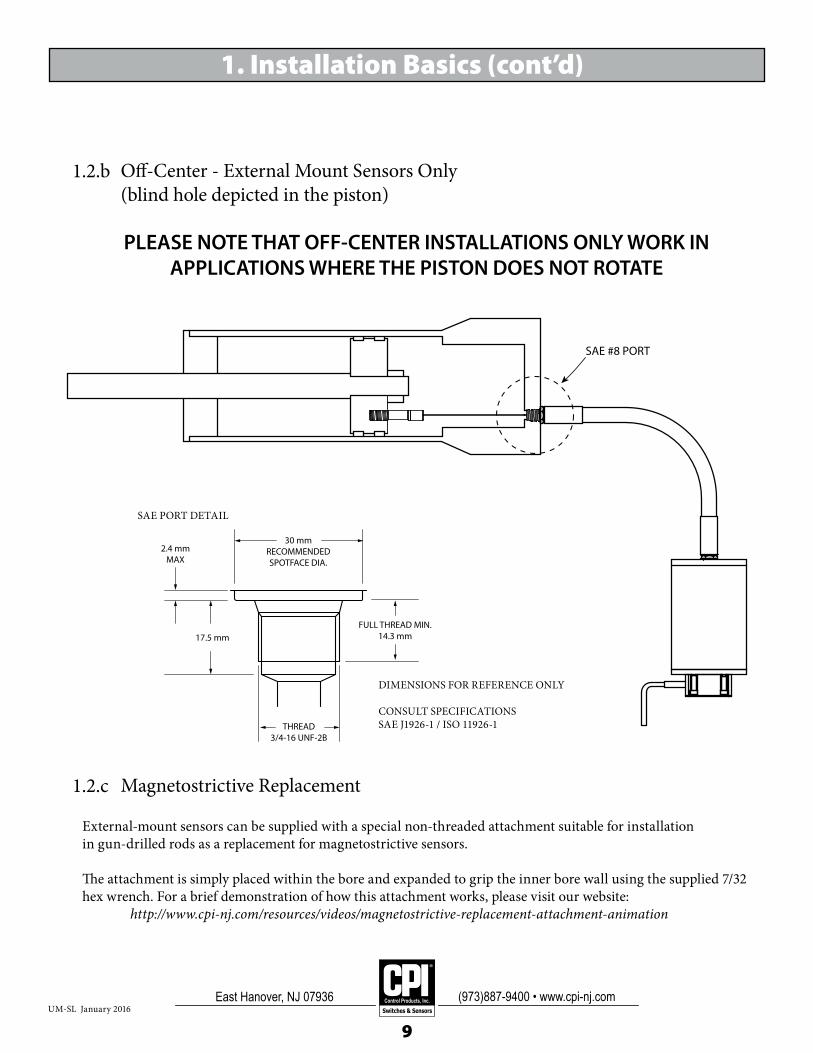
Off-Center - External Mount Sensors Only(blind hole depicted in the piston)
Magnetostrictive Replacement
1.2.b
1.2.c
PLEASE NOTE THAT OFF-CENTER INSTALLATIONS ONLY WORK IN APPLICATIONS WHERE THE PISTON DOES NOT ROTATE
SAE #8 PORT
1. Installation Basics (cont’d)
External-mount sensors can be supplied with a special non-threaded attachment suitable for installationin gun-drilled rods as a replacement for magnetostrictive sensors.
The attachment is simply placed within the bore and expanded to grip the inner bore wall using the supplied 7/32 hex wrench. For a brief demonstration of how this attachment works, please visit our website: http://www.cpi-nj.com/resources/videos/magnetostrictive-replacement-attachment-animation
THREAD3/4-16 UNF-2B
FULL THREAD MIN.14.3 mm
30 mmRECOMMENDEDSPOTFACE DIA.
17.5 mm
2.4 mmMAX
DIMENSIONS FOR REFERENCE ONLY
CONSULT SPECIFICATIONS SAE J1926-1 / ISO 11926-1
SAE PORT DETAIL
9

®
Switches & Sensors
Control Products, Inc.East Hanover, NJ 07936 (973)887-9400 • www.cpi-nj.comUM-SL January 2016
12 inchminimum diameter
(do not bend less than ø12”)
The external mount SL Series sensors afford tremendous flexibility for equipment designers, as the sensor can be located away from space constrained areas where there may be moving structures. The conduit (hydraulic hose) length can be specified by the designer, however the maximum length is subject to the demands of the application. Additionally, while there is a minimum bend radius for the flexible conduit for each sensor, again, the system operating characteristics must be accounted for. For example, in a high velocity application where the sensor is run dry, the concerns are:
1. Reduced velocity due to drag, which is increased with conduit length and bends in the conduit2. Wear in the conduit liner
The above is an extreme example. Generally, as long as the sensor is run in a pressurized hydraulic environment (i.e. lubricated), both of the above concerns are substantially reduced.
Minimum Bend Radius SL0390: 6 inches SL1200: 6 inches SL1400: 6 inches
1.3 ConduitLength/BendSL0390/SL1200/SL1490
1. Installation Basics (cont’d)
10

®
Switches & Sensors
Control Products, Inc.East Hanover, NJ 07936 (973)887-9400 • www.cpi-nj.comUM-SL January 2016
1.4Mounting(brackets,concepts)Control Products offers design support to customers to ensure successful deployment of SL Series sensors. We have found that no two applications are alike and this especially holds true for sensor mounting requirements.
Please feel free to contact the factory to discuss your sensor mounting challenges
Our SL0390 shown mounted in the field using a customer-designed bracket.
1. Installation Basics (cont’d)
11

®
Switches & Sensors
Control Products, Inc.East Hanover, NJ 07936 (973)887-9400 • www.cpi-nj.comUM-SL January 2016
2. Environmental Specifications
2.2EMI/RFIPlease contact us with your application requirements.
2.1TemperatureSLSERIESSENSORSWILLNOTOPERATEINFROZENMEDIA.
OperatingTemperaturesensor:
signal conditioner:
-40ºF (unfrozen media) to 300ºF / -40ºC (unfrozen media) to 105ºC (standard range; higher available) signal conditioner dependent
2.3SystemPressure2.3.aEnclosure:5000psi maximum working pressure
2.3.bHigh-pressureConnector:5000psi maximum working pressure
2.3.cConduit:3500psi maximum working pressure
Consult factory for higher pressure applications.
12

®
Switches & Sensors
Control Products, Inc.East Hanover, NJ 07936 (973)887-9400 • www.cpi-nj.comUM-SL January 2016
3. Electrical Connections
4. Fault IndicationAll SL Series sensors provide a proportional analog output over their entire stroke length—there is no end-of-stroke dead zone for any of these products. Fault indication is a feature inherent in the various analog outputs available from the signal conditioner (SL240, Macro Sensor LVC4000). In the case of the 0-5V output option, the full span of the sensor is typically defined by 0.5V to 4.5V. If the actual output is outside of these limits, that would indicate a fault condition. If the output drops to zero, for example, that might be an indication of a damaged or broken flexible connector. Other causes of fault conditions include broken LVDT wire(s) internal to the sensor or failed connection elsewhere between the sensor and signal conditioner.
ToconnectthesensorwirestopinsontheSC451high-pressureconnector:
1. Match the sensor wire color to the same color pin on the SC451 high-pressure connector2. Push each wire receptacle fully onto the corresponding color pin3. Carefully guide the wires into the hole while installing the plug with 4 bolts. Ensure the bolts are tight and the plug is fully seated and flat on the mounting surface.
NOTE: ALL SURFACES MUST BE CLEAN.APPLY A SMALL AMOUNT OF OIL TO THE PLUG AND O-RING.
Toconnectthecabletothesignalconditioner:
WIRECOLOR DESIGNATION SC240TERMINALNUMBER Black Secondary 1 Terminal 7 Brown Secondary 2 Terminal 8 Blue Primary 1 Terminal 4 White Primary 2 Terminal 3
13

®
Switches & Sensors
Control Products, Inc.East Hanover, NJ 07936 (973)887-9400 • www.cpi-nj.comUM-SL January 2016
5. MTBF
6. Specifications
The SL Series sensor system is comprised of three elements: The draw-wire coreAn LVDT (the core sensing technology)A signal conditioner
The draw-wire core is a highly integrated mechanical assembly with no electronic elements. As a mechanical assembly, there are many conditions specific to each application which impact its operation. Applying MTBF to the draw-wire core is not meaningful.
The LVDT is the only electronic component to any SL Series sensor. It is a non-contacting technology which will operate for an indefinite period estimated in years.
The signal conditioner converts the standard LVTD output to various proportional analog outputs. An example is CPI P/N SC240, which is manufactured by Macro Sensors, ref. P/N LVC-4000. Please contact the signal conditioner manufacturer for MTBF information
Resolution: ± .025”Repeatability: .025”Non-linearity: 2% of full scale output (FSO)Hysteresis: ± .010” MAX.InputVoltage: 9-30VDC typical*** (LVC4000) InputCurrent: 100mA typical @ 24VDC*** (LVC4000)OutputVoltage: 0-5V*** 0-10V 4-20mA Serial RS485OperatingTemperature: Sensor: -40ºC to 105ºC (-40ºF to 221ºF)** Signal Conditioner: signal conditioner dependentEMC: Emissions: Please consult factory Immunity: Please consult factory
Shock: 50g, 6ms, sawtoothVibration: 5g, 10Hz to 2kHzPressure: Operating: 5,000psi Spike: 10,000psiEndurance: 1 million full-stroke cyclesRecommendedCleanlinessLevel: ISO-19/18/15ColdOilPerformanceDelo400(MIL-PRF-46167): 1 ft. retraction: 1/2 second @ 0ºF* 3 seconds @ -25ºF* 24 seconds @ -50ºF*
* Will not operate in frozen liquid media** Standard temperature range. Greater temperatures available - please consult factory*** See MacroSensor LVC4000 User Manual
14

UM-SL January 2016
SL14907 Meters Internal
1 METER
3 METERS
7 METERS
The SL Family of Linear Position Sensors
SL03901 Meter Remote
SL13901 Meter Internal
SL12903 Meters Internal
SL14007 Meters Remote
SL12003 Meters Remote
Longer stroke sensors available. Please consult the factory for your long-stroke application requirements.
LONGER STROKES...
www.cpi-nj.com • [email protected]
®
Control Products, Inc.280 Ridgedale Ave.
East Hanover, NJ 07936Ph: (973) 887-9400 Fx: (973) 887-5083