Embed Size (px)
Citation preview

SL Paper 2
Markscheme
Examiners report
An ohmic conductor is connected to an ideal ammeter and to a power supply of output voltage V.
The following data are available for the conductor:
density of free electrons = 8.5 × 10 cm
resistivity ρ = 1.7 × 10 Ωm
dimensions w × h × l = 0.020 cm × 0.020 cm × 10 cm.
The ammeter reading is 2.0 A.
22 −3
−8
Calculate the resistance of the conductor. [2]a.
Calculate the drift speed v of the electrons in the conductor in cm s . State your answer to an appropriate number of significant figures.–1 [3]b.
1.7 × 10 ×
0.043 «Ω»
[2 marks]
–8a.
v «= » =
0.368 «cms »
0.37 «cms »
Award [2 max] if answer is not expressed to 2 sf.
[3 marks]
–1
–1
b.
[N/A]
theonlinephysicstutor.com
@TOPhysicsTutor facebook.com/TheOnlinePhysicsTutor

a. [N/A]b.
This question is in two parts. Part 1 is about simple harmonic motion (SHM) and sound. Part 2 is about electric and magnetic fields.
Part 1 Simple harmonic motion (SHM) and sound
The diagram shows a section of continuous track of a long-playing (LP) record. The stylus (needle) is placed in the track of the record.
As the LP record rotates, the stylus moves because of changes in the width and position of the track. These movements are converted into soundwaves by an electrical system and a loudspeaker.
A recording of a single-frequency musical note is played. The graph shows the variation in horizontal acceleration of the stylus with horizontaldisplacement.
Sound is emitted from a loudspeaker which is outside a building. The loudspeaker emits a sound wave that has the same frequency as the recorded
note.
A person standing at position 1 outside the building and a person standing at position 2 inside the building both hear the sound emitted by theloudspeaker.
theonlinephysicstutor.com
@TOPhysicsTutor facebook.com/TheOnlinePhysicsTutor

A, B and C are wavefronts emitted by the loudspeaker.
Part 2 Electric and magnetic fields
Electrical leads used in physics laboratories consist of a central conductor surrounded by an insulator.
Explain why the graph shows that the stylus undergoes simple harmonic motion. [4]a.
(i) Using the graph on page 14, show that the frequency of the note being played is about 200 Hz.
(ii) On the graph on page 14, identify, with the letter P, the position of the stylus at which the kinetic energy is at a maximum.
[5]b.
(i) Draw rays to show how the person at position 1 is able to hear the sound emitted by the loudspeaker.
(ii) The speed of sound in the air is . Calculate the wavelength of the note.
(iii) The walls of the room are designed to absorb sound. Explain how the person at position 2 is able to hear the sound emitted by theloudspeaker.
[4]c.
The arrangement in (c) is changed and another loudspeaker is added. Both loudspeakers emit the same recorded note in phase with each other.
Outline why there are positions between the loudspeakers where the sound can only be heard faintly.
[3]d.
Distinguish between an insulator and a conductor. [2]e.
The diagram shows a current I in a vertical wire that passes through a hole in a horizontal piece of cardboard.
On the cardboard, draw the magnetic field pattern due to the current.
[3]f.
(i) The diagram shows a length of copper wire that is horizontal in the magnetic field of the Earth. [4]g.
theonlinephysicstutor.com
@TOPhysicsTutor facebook.com/TheOnlinePhysicsTutor

Markscheme
The wire carries an electric current and the force on the wire is as shown. Identify, with an arrow, the direction of electron flow in the wire.
(ii) The horizontal component of the magnetic field of the Earth at the position of the wire is . The mass per unit length of the wire is . The net force on the wire is zero. Determine the current in the wire.
acceleration is proportional to displacement;
force/acceleration is directed towards equilibrium (point)/rest position; } (do not accept “centre” or “fixed” point)
straight line through the origin shows the proportionality;
negative gradient shows acceleration directed towards equilibrium (point) / acceleration has opposite sign to displacement;
a.
(i) gradient ;
;
;
;
or
;
;
;
;
Allow substitution for fourth mark.
(ii) at origin;
b.
(i) ray shown at 90° to wavefront A, plausible reflection and reflected ray goes in direction of position 1; } (judge by eye)
(ii) 1.65 (m); (allow ECF from (b)) (accept rounding to 1.6 or 1.7)
(iii) mention of diffraction;
diffraction means that sound spreads beyond the limit of geometrical shadow/can go around a corner / OWTTE;
Accept marking points in the form of a clearly drawn correctly labelled diagram.
c.
interference/superposition mentioned;
when sounds arrive out of phase / path difference half integer number of wavelengths / OWTTE;
cancellation occurs / destructive (interference);
some (back) reflection from walls so cancellation may not be complete (hence “faint” not “zero”);
d.
conductor has free electrons/charges that are free to move within/through it / insulator does not have free electrons/charges that are free to move
within/ through it;
electrons act as charge carriers;
when a pd acts across a conductor a current exists when charge (carriers) move;
e.
theonlinephysicstutor.com
@TOPhysicsTutor facebook.com/TheOnlinePhysicsTutor

Examiners report
Do not allow “good/bad conductor/resistor” or reference to conductivity/resistivity.
anti-clockwise arrows;
at least three circles centred on wire;
increasing in separation from centre;
f.
(i) arrow to the right;
(ii) ;
;
35 (A);
Award [3] for a bald correct answer.
Allow use of g = 10 m s which also gives an answer of 35 (A).–2
g.
It was rare to see all four marks awarded for statements of the requirements of harmonic oscillation and recognition of these in the straight-line
graph. Candidates were generally happy to state that acceleration is directly proportional to displacement and that the straight line through the
origin confirmed this. Correct statements with appropriate detail of the direction of the force/acceleration were rarer and the negative gradient was
not often mentioned. Four marks were available and therefore candidates should have recognised that four points were required.
a.
(i) This calculation was poorly done.
(ii) P – when it was marked on the graph at all – was either shown at the origin (correct) or one extreme (incorrect) of the graph in about equalnumbers.
b.
(i) Candidates are required to know the relationship between wavefronts and rays and it was surprising that many completed the diagram with
wavefronts – and even these would not have gained much credit given the very poor draughtsmanship in evidence. Few candidates bothered to
read the question. They failed to realise that all they were required to do was construct plausible incident and reflected rays that would enable the
observer at point 1 to hear the sound.
(ii) There were many examples of correct evaluation of the wavelength of the sound but far too many were unable to complete this simple task.Inversions of the equation and mistakes in powers of ten and in rounding were common.
(iii) The usual phonetic spelling of “defraction” was observed. Examiners are unlikely to give a benefit of the doubt to what might have been aphonetic spelling or might equally have been confusion with “refraction” in this particular case. Many candidates were able to spot that the soundwas being diffracted but an explanation of what diffraction is, in context, was much rarer.
c.
[N/A]d.Superficial answers were common. Candidates continue to ignore the mark allocations for questions and therefore the number of independent
points they should mention in an answer. Here, most said that conductors contain free electrons (or the reverse for insulators) but did not go on to
discuss the role of the free electrons in carrying charge or to relate the current to the existence of an electric field across the conductor. Far too
many gave answers of the “conductors conduct well” variety that do not score marks.
e.
There are three elements to a good drawing of the magnetic field around a long straight conductor: the concentric circularity of the lines, the
direction of the lines related to the direction of charge flow, and the increasing separation between lines as the distance from the conductor
increases. It was a rare candidate who was able to convince the examiner with all three points. In hindsight, the diagram could have been larger on
f.
theonlinephysicstutor.com
@TOPhysicsTutor facebook.com/TheOnlinePhysicsTutor

Markscheme
the page. However, candidates could have taken more trouble over their sketches which were usually crude.
(i) Many forgot that the sign rules involve conventional current and lost the mark.
(ii) Few correct solutions were observed. This was a straightforward problem involving one re-arrangement of a standard equation and theincorporation of the weight of the conductor.
g.
This question is about the internal resistance of a cell.
A circuit is used to determine the internal resistance and emf of a cell. It consists of the cell, a variable resistor, an ideal ammeter and an ideal
voltmeter. The diagram shows part of the circuit with the ammeter and voltmeter missing.
The variable resistor is set to . When the cell converts 7.2 mJ of energy, 5.8 mC of charge moves completely around the circuit. The potentialdifference across the variable resistor is 0.55 V.
Define electromotive force (emf ). [1]a.
Draw on the diagram the positions of the ammeter and voltmeter. [1]b.i.
Show that the emf of the cell is 1.25 V. [1]b.ii.
Determine the internal resistance of the cell. [2]b.iii.
Calculate the energy dissipated per second in the variable resistor. [2]b.iv.
energy/work per unit charge supplied (by a cell) driving the current completely around a circuit;
quantity of chemical/any form of energy, per unit charge, changed to electrical energy;
potential difference across a cell when no current flows;
Allow similar responses.
a.
ammeter in series with cell and voltmeter across cell or variable resistor; } (both needed)b.i.
(= 1.24 V or 1.25 V);
Answer is given so award the mark for showing the working.
b.ii.
;b.iii.
theonlinephysicstutor.com
@TOPhysicsTutor facebook.com/TheOnlinePhysicsTutor

Examiners report
; (accept valid alternative method)
use of or alternative;
0.20 W;
b.iv.
Very few precise answers. Most candidates almost knew what it was but were unable to define it with the necessary precision.a.
[N/A]b.i.[N/A]b.ii.[N/A]b.iii.[N/A]b.iv.
This question is in two parts. Part 1 is about kinematics and Newton’s laws of motion.
Part 2 is about electrical circuits.
Part 1 Kinematics and Newton’s laws of motion
Cars I and B are on a straight race track. I is moving at a constant speed of and B is initially at rest. As I passes B, B starts to move with anacceleration of .
At a later time B passes I. You may assume that both cars are point particles.
A third car O with mass 930 kg joins the race. O collides with I from behind, moving along the same straight line as I. Before the collision the speed of I
is and its mass is 850 kg. After the collision, I and O stick together and move in a straight line with an initial combined speed of .
This question is in two parts. Part 1 is about kinematics and Newton’s laws of motion.
Part 2 Electrical circuits
The circuit shown is used to investigate how the power developed by a cell varies when the load resistance changes.
The variable resistor is adjusted and a series of current and voltage readings are taken. The graph shows the variation with of the power dissipatedin the cell and the power dissipated in the variable resistor.
theonlinephysicstutor.com
@TOPhysicsTutor facebook.com/TheOnlinePhysicsTutor

Markscheme
The cell has an internal resistance.
Show that the time taken for B to pass I is approximately 28 s. [4]a.i.
Calculate the distance travelled by B in this time. [2]a.ii.
B slows down while I remains at a constant speed. The driver in each car wears a seat belt. Using Newton’s laws of motion, explain the
difference in the tension in the seat belts of the two cars.
[3]b.
Calculate the speed of O immediately before the collision. [2]c.i.
The duration of the collision is 0.45 s. Determine the average force acting on O. [2]c.ii.
An ammeter and a voltmeter are used to investigate the characteristics of a variable resistor of resistance . State how the resistance of the
ammeter and of the voltmeter compare to so that the readings of the instruments are reliable.
[2]d.
Show that the current in the circuit is approximately 0.70 A when . [3]e.
Outline what is meant by the internal resistance of a cell. [2]f.i.
Determine the internal resistance of the cell. [3]f.ii.
Calculate the electromotive force (emf) of the cell. [2]g.
distances itemized; (it must be clear through use of or distance I etc)
distances equated;
/ cancel and re-arrange;
substitution shown / 28.1(s) seen;
a.i.
theonlinephysicstutor.com
@TOPhysicsTutor facebook.com/TheOnlinePhysicsTutor

or
clear written statement that the average speed of B must be the same as constant speed of I;
as B starts from rest the final speed must be ;
so ;
28.1 (s) seen; (for this alternative the method must be clearly described)
or
attempts to compare distance travelled by I and B for 28 s;
I distance ;
B distance ;
deduces that overtake must occur about later;
use of appropriate equation of motion;
1.3 (km);
Award [2] for a bald correct answer.
a.ii.
driver I moves at constant speed so no net (extra) force according to Newton 1;
driver B decelerating so (extra) force (to rear of car) (according to Newton 1) / momentum/inertia change so (extra) force must be present;
(hence) greater tension in belt B than belt I;
Award [0] for stating that tension is less in the decelerating car (B).
b.
or statement that momentum is conserved;
;
Allow [2] for a bald correct answer.
c.i.
use of force (or any variant, eg: );
; } (must see matched units and value ie: 13 200 without unit gains MP2, 13.2 does not)
Award [2] for a bald correct answer.
Allow use of 58 m s from (c)(i) to give 12 400 (N).–1
c.ii.
ammeter must have very low resistance/much smaller than ;
voltmeter must have very large resistance/much larger than ;
Allow [1 max] for zero and infinite resistance for ammeter and voltmeter respectively.
Allow [1 max] if superlative (eg: very/much/OWTTE) is missing.
d.
power (loss in resistor) ; } (accept answers in the range of 0.35 to 0.37 (W) – treat value outside this range as ECF (could still lead to
0.7))
;
or ; (allow answers in the range of 0.66 to 0.68 (A).
e.
resistance of the components/chemicals/materials within the cell itself; } (not “resistance of cell”)
leading to energy/power loss in the cell;
f.i.
power (in cell with 0.7 A) ; } (allow answers in the range of 0.57 W to 0.62 W)f.ii.
theonlinephysicstutor.com
@TOPhysicsTutor facebook.com/TheOnlinePhysicsTutor

Examiners report
;
; (allow answers in the range of 1.18 to 1.27 ( ))
or
when powers are equal;
;
so which occurs at 1.2(5) ( );
Award [1 max] for bald 1.2(5) ( ).
;
1.4 (V);
Allow ECF from (e) or (f)(ii).
or
when , power loss ;
;
g.
[N/A]a.i.[N/A]a.ii.[N/A]b.[N/A]c.i.[N/A]c.ii.[N/A]d.[N/A]e.[N/A]f.i.[N/A]f.ii.[N/A]g.
This question is in two parts. Part 1 is about the motion of a car. Part 2 is about electricity.
Part 1 Motion of a car
A car is travelling along the straight horizontal road at its maximum speed of . The power output required at the wheels is 0.13 MW.
A driver moves the car in a horizontal circular path of radius 200 m. Each of the four tyres will not grip the road if the frictional force between a tyre and
the road becomes less than 1500 N.
Part 2 Electricity
A lemon can be used to make an electric cell by pushing a copper rod and a zinc rod into the lemon.
theonlinephysicstutor.com
@TOPhysicsTutor facebook.com/TheOnlinePhysicsTutor

A student constructs a lemon cell and connects it in an electrical circuit with a variable resistor. The student measures the potential difference V acrossthe lemon and the current I in the lemon.
A car accelerates uniformly along a straight horizontal road from an initial speed of to a final speed of in a distance of 250
m. The mass of the car is 1200 kg. Determine the rate at which the engine is supplying kinetic energy to the car as it accelerates.
[4]a.
A car is travelling along a straight horizontal road at its maximum speed of . The power output required at the wheels is 0.13 MW.
(i) Calculate the total resistive force acting on the car when it is travelling at a constant speed of .
(ii) The mass of the car is 1200 kg. The resistive force is related to the speed by . Using your answer to (b)(i), determine themaximum theoretical acceleration of the car at a speed of .
[5]b.
(i) Calculate the maximum speed of the car at which it can continue to move in the circular path. Assume that the radius of the path is the
same for each tyre.
(ii) While the car is travelling around the circle, the people in the car have the sensation that they are being thrown outwards. Outline howNewton’s first law of motion accounts for this sensation.
[6]c.
(i) Draw a circuit diagram of the experimental arrangement that will enable the student to collect the data for the graph.
(ii) Show that the potential difference across the lemon is given by
where is the emf of the lemon cell and is the internal resistance of the lemon cell.
(iii) The graph shows how varies with .
Using the graph, estimate the emf of the lemon cell.
(iv) Determine the internal resistance of the lemon cell.
(v) The lemon cell is used to supply energy to a digital clock that requires a current of . The clock runs for 16 hours. Calculate thecharge that flows through the clock in this time.
[10]d.
theonlinephysicstutor.com
@TOPhysicsTutor facebook.com/TheOnlinePhysicsTutor

Markschemeuse of a kinematic equation to determine motion time ;
change in kinetic energy ;
rate of change in kinetic energy ; } (allow ECF of 162 from (28 – 12) for this mark)
31 (kW);
or
use of a kinematic equation to determine motion time ;
use of a kinematic equation to determine acceleration ;
work done ;
31 (kW);
2
a.
(i) ;
2300 or 2.3k (N);
Award [2] for a bald correct answer.
(ii) resistive force or ; (allow ECF)
so accelerating force = or 1741 (N);
or ;
Award [2 max] for an answer of 0.49 (m s ) (omits 2300 N).–2
b.
(i) centripetal force must be ; (allow force = 6000 N)
;
;
Allow [3] for a bald correct answer.
Allow [2 max] if 4 is omitted, giving 15.8 (m s ).
(ii) statement of Newton’s first law;
(hence) without car wall/restraint/friction at seat, the people in the car would move in a straight line/at a tangent to circle;
(hence) seat/seat belt/door exerts centripetal force;
(in frame of reference of the people) straight ahead movement is interpreted as “outwards”;
–1
c.
(i) voltmeter in parallel with cell; (allow ammeter within voltmeter leads)
ammeter in series with variable resistor; } (must draw as variable arrangement or as potential divider)
Allow cell symbol for lemon/cell/box labelled “lemon cell”.
Award [1 max] if additional cell appears in the circuit.
(ii) and used; (must state both explicitly)
re-arrangement correct ie ; } (accept any other correct re-arrangement eg. involving energy conversion)
(iii) line correctly extrapolated to y-axis; (judge by eye)
1.6 or 1.60 (V); (allow ECF from incorrect extrapolation)
(iv) correct read-offs from large triangle greater than half line length;
gradient determined;
290 to 310 ;
d.
theonlinephysicstutor.com
@TOPhysicsTutor facebook.com/TheOnlinePhysicsTutor

Examiners report
Award [2 max] for the use of one point on line and equation.
(v) 0.35 (C);
There were at least two routes to tackle this problem. Some solutions were so confused that it was difficult to decide which method had been
used. Common errors included: forgetting that the initial speed was not zero, power of ten errors, and simple mistakes in the use of the
kinematic equations, or failure to evaluate work done = force distance correctly. However, many candidates scored partial credit. Scores of two
or three out of the maximum four were common showing that many are persevering to get as far as they can.
a.
(i) Many correct solutions were seen. Candidates are clearly comfortable with the use of the equation force = power/speed.
(ii) The method to be used here was obvious to many. What was missing was a clear appreciation of what was happening in terms of resistiveforce in the system. Many scored two out of three because they indicated a sensible method but did not use the correct value for the force.Scoring two marks does require that the explanation of the method is at least competent. Those candidates who give limited explanations of theirmethod leading to a wrong answer will generally accumulate little credit. A suggestion (never seen in answers) is that candidates should havebegun from a free-body force diagram which would have revealed the relationship of all the forces.
b.
(i) The major problem here was that most candidates did not recognise that 1500 N of force acting at each of four wheels will imply a total force
of 6 kN. Again, partial credit was available only if it was clear what the candidate was doing and what the error was.
(ii) Statements of Newton’s first law were surprisingly poor. As in previous examinations, few candidates appear to have learnt this essential ruleby heart and they produce a garbled and incomplete version under examination pressure. The first law was then only loosely connected to theparticular context of the question. Candidates have apparently not learnt to relate the physics they learn to everyday contexts.
c.
(i) Circuit diagrams continue to be a particular issue for many candidates. Neat, well-drawn diagrams are rarely seen. Some diagrams had two
cells, the lemon cell and another. Variable resistors were sometimes absent (or were drawn as fixed). Potential dividers were often attempted
usually unsuccessfully. Generally candidates gained an average one mark for what should have been a familiar task.
(ii) Those who quoted the data booklet equation and the definition of resistance were generally able to show the final expression. Some howevercould not convince the examiners that they knew what they were doing.
(iii) Candidates were expected to understand the physical point that the emf can be determined when the current in the cell is zero. For many, anextrapolation of the obvious straight line to the emf axis and a correct read-off gave an easy couple of marks. Some however did not understandthe physics of the circuit and gave poorly described solutions.
(iv) The internal resistance was best obtained from a large triangle drawn on the graph. Many however gained two of the three marks becausethey engendered power of ten errors or because they used only one point, or because their triangle was too small.
(v) Only a minority were able to use the data to calculate the charge transferred correctly.
d.
A heater in an electric shower has a power of 8.5 kW when connected to a 240 V electrical supply. It is connected to the electrical supply by a copper
cable.
The following data are available:
Length of cable = 10 mCross-sectional area of cable = 6.0 mmResistivity of copper = 1.7 × 10 Ω m
2
–8
Calculate the current in the copper cable. [1]a.i.
theonlinephysicstutor.com
@TOPhysicsTutor facebook.com/TheOnlinePhysicsTutor

Markscheme
Examiners report
Calculate the resistance of the cable. [2]a.ii.
Explain, in terms of electrons, what happens to the resistance of the cable as the temperature of the cable increases. [3]b.
The heater changes the temperature of the water by 35 K. The specific heat capacity of water is 4200 J kg K .
Determine the rate at which water flows through the shower. State an appropriate unit for your answer.
–1 –1 [4]c.
I «= » =35«A»
a.i.
R =
= 0.028 «Ω»
Allow missed powers of 10 for MP1.
a.ii.
«as temperature increases» there is greater vibration of the metal atoms/lattice/lattice ions
OR
increased collisions of electrons
drift velocity decreases «so current decreases»
«as V constant so» R increases
Award [0] for suggestions that the speed of electrons increases so resistance decreases.
b.
recognition that power = flow rate × cΔT
flow rate « »
= 0.058 «kg s »
kg s / g s / l s / ml s / m s
Allow MP4 if a bald flow rate unit is stated. Do not allow imperial units.
–1
−1 −1 −1 −1 3 −1
c.
[N/A]a.i.[N/A]a.ii.[N/A]b.[N/A]c.
This question is in two parts. Part 1 is about a lightning discharge. Part 2 is about fuel for heating.
theonlinephysicstutor.com
@TOPhysicsTutor facebook.com/TheOnlinePhysicsTutor

Part 1 Lightning discharge
The magnitude of the electric field strength between two infinite charged parallel plates is given by the expression
where is the charge per unit area on one of the plates.
A thundercloud carries a charge of magnitude 35 C spread over its base. The area of the base is .
Part 2 Fuel for heating
A room heater burns liquid fuel and the following data are available.
Define electric field strength. [2]Part1.a.
A thundercloud can be modelled as a negatively charged plate that is parallel to the ground.
The magnitude of the charge on the plate increases due to processes in the atmosphere. Eventually a current discharges from the thundercloudto the ground.
On the diagram, draw the electric field pattern between the thundercloud base and the ground.
[3]Part1.b.
(i) Determine the magnitude of the electric field between the base of the thundercloud and the ground.
(ii) State two assumptions made in (c)(i).
1.
2.
(iii) When the thundercloud discharges, the average discharge current is 1.8 kA. Estimate the discharge time.
(iv) The potential difference between the thundercloud and the ground before discharge is . Determine the energy released in thedischarge.
[12]Part1.c.
Define the energy density of a fuel. [1]Part2.a.
(i) Use the data to calculate the power output of the room heater, ignoring the power required to convert the liquid fuel into a gas.
(ii) Show why, in your calculation in (b)(i), the power required to convert the liquid fuel into a gas at its boiling point can be ignored.
[5]Part2.b.
theonlinephysicstutor.com
@TOPhysicsTutor facebook.com/TheOnlinePhysicsTutor

Markscheme
State, in terms of molecular structure and their motion, two differences between a liquid and a gas.
1.
2.
[2]Part2.c.
force acting per unit charge;
on positive test / point charge;
Part1.a.
lines connecting plate and ground equally spaced in the central region of thundercloud and touching both plates; (judge by eye)
edge effects shown; (accept either edge effect A or B shown on diagram)
field direction correct;
Part1.b.
(i) ;
;
or ;
Award [3] for bald correct answer.
(ii) edge of thundercloud parallel to ground;
thundercloud and ground effectively of infinite length;
permittivity of air same as vacuum;
(iii) ;
;
;
(iv) use of energy ;
;
;
;
Award [3 max] for 8.8 GJ if average p.d. point omitted.
Accept solution which uses average current .
Allow ecf from (c)(ii).
Part1.c.
energy (released) per unit mass;
Accept per unit volume or per kg or per m .
Do not accept per unit density.
3
Part2.a.
theonlinephysicstutor.com
@TOPhysicsTutor facebook.com/TheOnlinePhysicsTutor

Examiners report
(i) volume of fuel used per second ;
;
;
Award [3] for bald correct answer.
(ii) power required ;
small fraction/less than 1% of overall power output / OWTTE;
Part2.b.
sensible comment comparing molecular structure;
e.g. liquid molecular structure (more) ordered than that of a gas.
in gas molecules far apart/about 10 molecular spacings apart / in liquid molecules close/touching.
sensible comment comparing motion of molecules;
e.g. in liquid: molecules interchange places with neighbouring molecules / no longdistance motion.in gases: no long-range order / long distance motion.
Part2.c.
Many omitted the reference to a test charge that is positive.Part1.a.
Common errors were to draw the field lines in the wrong direction, to omit edge effects, and to fail to draw field lines that touch the plates.Part1.b.
(i) This part was well done.
(ii) Most candidates could only identify one assumption made in the calculation.
(iii) The estimation of discharge time was well done.
(iv) There was a general failure to recognise that the average pd during the discharge is half the maximum (starting) value and this lost a mark.
Part1.c.
A handful of candidates defined energy density as energy converted per unit density, but most gave energy released per unit mass with a minority
quoting energy released per unit volume.
Part2.a.
(i) Again, this was done well by the majority with the usual smattering of significant figure penalties and mistakes in handling powers of ten.
(ii) Arguments were weak and poorly supported by calculation.
Part2.b.
Candidates found great difficulty in stating the differences between liquids and gases. They often focused on either molecular structure or motion,
but not both as required in the question.
Part2.c.
An electron moves in circular motion in a uniform magnetic field.
theonlinephysicstutor.com
@TOPhysicsTutor facebook.com/TheOnlinePhysicsTutor

Markscheme
Examiners report
The velocity of the electron at point P is 6.8 × 10 m s in the direction shown.
The magnitude of the magnetic field is 8.5 T.
5 –1
State the direction of the magnetic field. [1]a.
Calculate, in N, the magnitude of the magnetic force acting on the electron. [1]b.
Explain why the electron moves at constant speed. [1]c.i.
Explain why the electron moves on a circular path. [2]c.ii.
out of the page plane / ⊙
Do not accept just “up” or “outwards”.
[1 mark]
a.
1.60 × 10 × 6.8 × 10 × 8.5 = 9.2 × 10 «N»
[1 mark]
–19 5 –13b.
the magnetic force does not do work on the electron hence does not change the electron’s kinetic energy
OR
the magnetic force/acceleration is at right angles to velocity
[1 mark]
c.i.
the velocity of the electron is at right angles to the magnetic field
(therefore) there is a centripetal acceleration / force acting on the charge
OWTTE
[2 marks]
c.ii.
[N/A]a.[N/A]b.[N/A]c.i.[N/A]c.ii.
The diagram shows a potential divider circuit used to measure the emf E of a cell X. Both cells have negligible internal resistance.
theonlinephysicstutor.com
@TOPhysicsTutor facebook.com/TheOnlinePhysicsTutor

Markscheme
Examiners report
AB is a wire of uniform cross-section and length 1.0 m. The resistance of wire AB is 80 Ω. When the length of AC is 0.35 m the current in cell X is zero.
State what is meant by the emf of a cell. [2]a.
Show that the resistance of the wire AC is 28 Ω. [2]b.i.
Determine E. [2]b.ii.
the work done per unit charge
in moving charge from one terminal of a cell to the other / all the way round the circuit
Award [1] for “energy per unit charge provided by the cell”/“power per unit current”
Award [1] for “potential difference across the terminals of the cell when no current is flowing”
Do not accept “potential difference across terminals of cell”
[2 marks]
a.
the resistance is proportional to length / see 0.35 AND 1«.00»
so it equals 0.35 × 80
«= 28 Ω»
[2 marks]
b.i.
current leaving 12 V cell is = 0.15 «A»
OR
E = × 28
E = «0.15 × 28 =» 4.2 «V»
Award [2] for a bald correct answer
Allow a 1sf answer of 4 if it comes from a calculation.
Do not allow a bald answer of 4 «V»
Allow ECF from incorrect current
[2 marks]
b.ii.
[N/A]
Markscheme
Examiners report
a. [N/A]b.i.[N/A]b.ii.
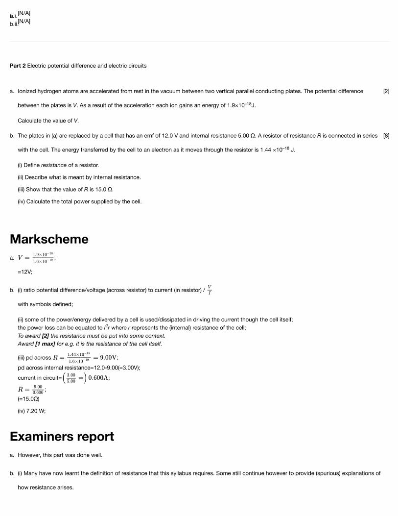
Part 2 Electric potential difference and electric circuits
Ionized hydrogen atoms are accelerated from rest in the vacuum between two vertical parallel conducting plates. The potential difference
between the plates is V. As a result of the acceleration each ion gains an energy of 1.9×10 J.
Calculate the value of V.
–18
[2]a.
The plates in (a) are replaced by a cell that has an emf of 12.0 V and internal resistance 5.00 Ω. A resistor of resistance R is connected in series
with the cell. The energy transferred by the cell to an electron as it moves through the resistor is 1.44 ×10 J.
(i) Define resistance of a resistor.
(ii) Describe what is meant by internal resistance.
(iii) Show that the value of R is 15.0 Ω.
(iv) Calculate the total power supplied by the cell.
–18
[8]b.
;
=12V;
a.
(i) ratio potential difference/voltage (across resistor) to current (in resistor) /
with symbols defined;
(ii) some of the power/energy delivered by a cell is used/dissipated in driving the current though the cell itself;the power loss can be equated to I r where r represents the (internal) resistance of the cell; To award [2] the resistance must be put into some context.Award [1 max] for e.g. it is the resistance of the cell itself.
(iii) pd across ;pd across internal resistance=12.0-9.00(=3.00V);current in circuit= ;
;(=15.0Ω)
(iv) 7.20 W;
2
b.
However, this part was done well.a.
(i) Many have now learnt the definition of resistance that this syllabus requires. Some still continue however to provide (spurious) explanations of
how resistance arises.
b.
(ii) This was a description and many candidates were able to gain one point. But the second point for an analysis of the internal power dissipationof a cell was universally absent.
This question is in two parts. Part 1 is about energy resources. Part 2 is about electric fields.
Part 1 Energy resources
A photovoltaic panel is made up of a collection (array) of photovoltaic cells. The panel has a total area of and is mounted on the roof of a
house. The maximum intensity of solar radiation at the location of the panel is . The panel produces a power output of 210 W when the
solar radiation is at its maximum intensity.
The owner of the house chooses between photovoltaic panels and solar heating panels to provide 4.2 kW of power to heat water. The solar heating
panels have an efficiency of 70%. The maximum intensity of solar radiation at the location remains at .
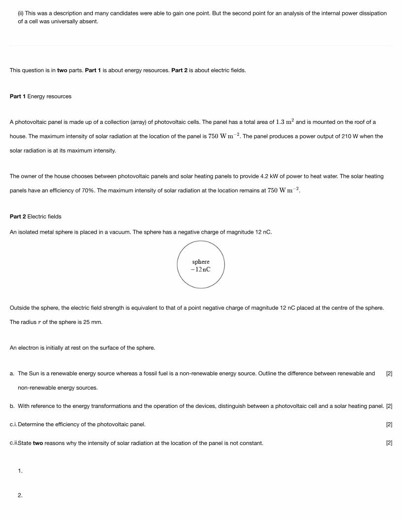
Part 2 Electric fields
An isolated metal sphere is placed in a vacuum. The sphere has a negative charge of magnitude 12 nC.
Outside the sphere, the electric field strength is equivalent to that of a point negative charge of magnitude 12 nC placed at the centre of the sphere.
The radius of the sphere is 25 mm.
An electron is initially at rest on the surface of the sphere.
The Sun is a renewable energy source whereas a fossil fuel is a non-renewable energy source. Outline the difference between renewable and
non-renewable energy sources.
[2]a.
With reference to the energy transformations and the operation of the devices, distinguish between a photovoltaic cell and a solar heating panel. [2]b.
Determine the efficiency of the photovoltaic panel. [2]c.i.
State two reasons why the intensity of solar radiation at the location of the panel is not constant.
1.
2.
[2]c.ii.

Markscheme
Calculate the minimum area of solar heating panel required to provide this power. [2]d.i.
Comment on whether it is better to use a solar heating panel rather than an array of photovoltaic panels for the house. Do not consider the
installation cost of the panels in your answer.
[2]d.ii.
Using the diagram, draw the electric field pattern due to the charged sphere. [2]f.
Show that the magnitude of the electric field strength at the surface of the sphere is about . [2]g.i.
On the axes, draw a graph to show the variation of the electric field strength with distance from the centre of the sphere. [2]g.ii.
Calculate the initial acceleration of the electron. [2]h.i.
Discuss the subsequent motion of the electron. [2]h.ii.
renewable sources:
rate of use/depletion of energy source;
is less than rate of production/regeneration of source;
Accept equivalent statement for non-renewable sources.
or
mention of rate of production / usage;
comparison of sources in terms of being used up/depleted/lasting a long time etc;
Award [1] if answer makes clear the difference but does not address the rate of production.
a.
solar heating panel converts solar/radiation/photon/light energy into thermal/heat energy and photovoltaic cell converts solar/radiation/photon/light
energy into electrical energy; } (both needed)
in solar heating hot liquid is stored/circulated and photovoltaic cell generates emf/pd; } (both needed)
b.
(power available at roof) ;
efficiency or 22%;
c.i.

Examiners report
depends on time of day;
depends of time of year;
depends on weather (eg cloud cover) at location;
power output of Sun varies;
Earth-Sun distance varies;
c.ii.
area of panel ;
;
d.i.
calculates area of photovoltaic panels needed as about / makes a quantitative comparison;
solar heating takes up less area/more efficient/faster;
further energy conversion needed, from electrical to thermal, with photovoltaic panels, involving further losses / OWTTE;
Allow ECF from (d)(i) with appropriate reverse argument.
d.ii.
radial field with arrows and direction correct towards the sphere; (both needed)
no field inside sphere;
At least four lines of force to be shown on diagram.
f.
use of ;
; (must see answer to 2+ significant figures)
g.i.
line drawn showing zero field strength inside sphere;
decreasing in inverse square-like way from a value of or at the surface, ;
g.ii.
force ; (allow use of )
acceleration ;
h.i.
radially away from sphere / away from centre of sphere;
velocity increasing but at a decreasing rate / accelerating with decreasing acceleration;
because (electric) field (strength) is decreasing;
h.ii.
[N/A]a.[N/A]b.[N/A]c.i.[N/A]c.ii.[N/A]d.i.[N/A]d.ii.It was disappointing to see some candidates sketching very imprecise lines. Most fields were radial, but often with incorrect direction.f.
Another “show that” question which often elicited a jumble of numbers. Line of reasoning needs to be clear. Although there were many
arithmetic/POT mistakes the field strength was often given correctly.
g.i.
It was extremely rare to find a zero line for the field inside of the sphere. The inverse square drop-off was often very approximate and did not
always start from the surface of the sphere. The line should not touch the -axis, but often did.
g.ii.
Markscheme
This was done correctly by a minority of candidates with many arithmetic and POT errors.h.i.
Some candidates clearly do not fully understand the difference between velocity and acceleration. It was rare to find that direction of motion was
given with precision. Some candidates said that the electron would stop as the field strength approached zero.
h.ii.
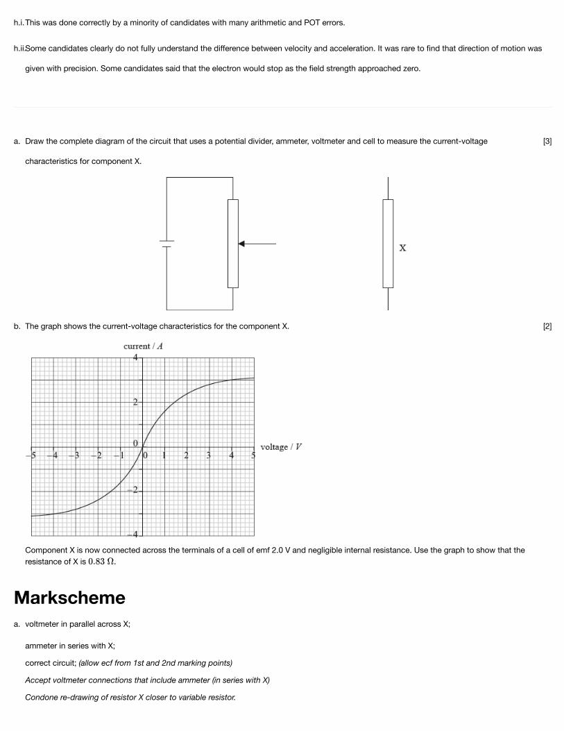
Draw the complete diagram of the circuit that uses a potential divider, ammeter, voltmeter and cell to measure the current-voltage
characteristics for component X.
[3]a.
The graph shows the current-voltage characteristics for the component X.
Component X is now connected across the terminals of a cell of emf 2.0 V and negligible internal resistance. Use the graph to show that theresistance of X is .
[2]b.
voltmeter in parallel across X;
ammeter in series with X;
correct circuit; (allow ecf from 1st and 2nd marking points)
Accept voltmeter connections that include ammeter (in series with X)
Condone re-drawing of resistor X closer to variable resistor.
a.

Examiners report
Markscheme
at 2.0 V;
;
Award [1 max] for use of gradient of graph from (2,2.4) to origin.
b.
Circuit diagrams of the potential divider were very poor although most were able to predict the correct positions for the ammeter and voltmeter.a.
Most candidates achieved full marks here.b.
Part 2 Gravitational fields and electric fields
The magnitude of gravitational field strength g is defined from the equation shown below.
The magnitude of electric field strength E is defined from the equation shown below.
For each of these defining equations, state the meaning of the symbols
(i) F .
(ii) F .
(iii) m.
(iv) q.
g
E
[4]a.
In a simple model of the hydrogen atom, the electron is regarded as being in a circular orbit about the proton. The magnitude of the electric field
strength at the electron due to the proton is E . The magnitude of the gravitational field strength at the electron due to the proton is g .
(i) Draw the electric field pattern of the proton alone.
(ii) Determine the order of magnitude of the ratio shown below.
p p
[5]b.

Examiners report
(i) the force exerted on a small/test/point mass;
Do not allow bald “gravitational force”.
(ii) the force exerted on a small/point/test positive charge; To award [1] “positive” is required.Do not allow bald “electric force”.
(iii) the size/magnitude/value of the small/point mass; Do not accept bald “mass”.
(iv) the magnitude/size/value of the small/point/test (positive) charge;Do not accept bald “charge”.
a.
(i)
pattern correct with at least 8 symmetrical lines as shown;direction correct;
(ii) and ; (both needed)
;
1028 ;
b.
In this part candidates were completely at a loss and could not state the meanings of the symbols in the definitions of gravitational or electric field
strengths. This was a disappointing failure in what was meant to be an easy opener to the whole question.
a.
(i) The diagrams presented to examiners frequently gave a clear indication of the direction and shape of the field pattern. This was well done.
(ii) Following(a) candidates failed widely on this part too. They often had little idea which data to use (mass and charge were frequently confused)and sometimes the meaning of the constants in the equations failed them too. This was compounded by arithmetic errors to make astraightforward calculation very hard for many.
b.
This question is in two parts. Part 1 is about electric charge and electric circuits. Part 2 is about momentum.
Part 1 Electric charge and electric circuits
State Coulomb’s law. [2]a.
In a simple model of the hydrogen atom, the electron can be regarded as being in a circular orbit about the proton. The radius of the orbit is
2.0×10 m.
(i) Determine the magnitude of the electric force between the proton and the electron.
(ii) Calculate the magnitude of the electric field strength E and state the direction of the electric field due to the proton at a distance of 2.0×10m from the proton.
–10
–10
[7]b.

Markscheme
(iii) The magnitude of the gravitational field due to the proton at a distance of 2.0×10 m from the proton is H.Show that the ratio is of the order 10 C kg .
(iv) The orbital electron is transferred from its orbit to a point where the potential is zero. The gain in potential energy of the electron is 5.4×10J. Calculate the value of the potential difference through which the electron is moved.
–10
–28 –1
–
19
An electric cell is a device that is used to transfer energy to electrons in a circuit. A particular circuit consists of a cell of emf ε and internal
resistance r connected in series with a resistor of resistance 5.0 Ω.
(i) Define emf of a cell.
(ii) The energy supplied by the cell to one electron in transferring it around the circuit is 5.1×10 J. Show that the emf of the cell is 3.2V.
(iii) Each electron in the circuit transfers an energy of 4.0×10 J to the 5.0 Ω resistor. Determine the value of the internal resistance r.
–19
–19
[6]c.
the force between two (point) charges;
is inversely proportional to the square of their separation and (directly) proportional to (the product of) their magnitudes;
Allow [2] for equation with F, Q and r defined.
a.
(i) ;
=5.8×10 (N);
Award [0] for use of masses in place of charges.
(ii) ( or 3.6 x 10 (NC ) or (Vm );(directed) away from the proton;Allow ECF from (b)(i).Do not penalize use of masses in both (b)(i) and (b)(ii) – allow ECF.
(iii) ;
or 7.8×10 (Ckg );(≈10 Ckg )Allow ECF from (b)(i).
(iv) 3.4(V);
-9
10 -1 -1
-29 -1
28 -1
b.
(i) power supplied per unit current / energy supplied per unit charge / work done per unit charge;
(ii) energy supplied per coulomb= or 3.19(V);
(≈3.2V)
(iii) pd across 5.0Ω resistor= ;
pd across r=(3.2-2.5=)0.70(V);
and
either
current in circuit= ;
resistance of r= ;
or
resistance of r= ;=1.4(Ω);
c.

Examiners report
or
3.2=0.5(R+r);resistance of r=1.4(Ω);Award [4] for alternative working leading to correct answer.Award [4] for a bald correct answer.
Many were able to state Coulomb’s law or to give the equation with explanations of the symbols. Some candidates however failed to define their
symbols and lost marks.
a.
(i) The electric force was calculated well by many.
(ii) The answer to (i) was well used to determine the magnitude of E. However, many candidates did not read the question and failed to state thedirection of the field or gave it in an ambiguous way.
(iii) Calculations to show the order of magnitude of H/E were generally well done. The last step was often missing with the answer simply given as afraction.
(iv) Many obtained this simple mark.
b.
(i) Many candidates gave confused or incorrect definitions of the emf of a cell. Previous comments in this report on the memorizing of definitions
apply. Too many had recourse to the next part and used this idea in their answer.
(ii) This was well done.
(iii) A large number of candidates completed this calculation stylishly, generally explaining steps (or at least writing down the algebra) in a logicalway. There were many correct and original solutions that gained full marks.
c.
Part 2 Electric motor
An electric motor is used to raise a load.
Whilst being raised, the load accelerates uniformly upwards. The weight of the cable is negligible compared to the weight of the load.
(i) Draw a labelled free-body force diagram of the forces acting on the accelerating load. The dot below represents the load.
[6]a.

Markscheme
(ii) The load has a mass of 350 kg and it takes 6.5 s to raise it from rest through a height of 8.0 m.
Determine the tension in the cable as the load is being raised.
The electric motor can be adjusted such that, after an initial acceleration, the load moves at constant speed. The motor is connected to a 450 V
supply and with the load moving at constant speed, it takes the motor 15 s to raise the load through 7.0 m.
(i) Calculate the power delivered to the load by the motor.
(ii) The current in the motor is 30 A. Estimate the efficiency of the motor.
[4]b.

Examiners report
(i) upward arrow labelled T/tension/force in cable and downward arrow labelled W/mg/weight/gravity force;{ (both needed)
tension arrow length >weight length;
(ii) ;
;
T=ma+mg or T=350(0.38+9.8);3.6 kN;Allow g=10 N kg (same answer to 2 sf).-1
a.
(i) change in gpe=350×9.81×7.0(=24kJ);
power ;
Allow g=10Nkg .
(ii) power input to motor=13.5 (kW);efficiency= or 12%;
-1
b.
[N/A]a.[N/A]b.
Electrical resistors can be made by forming a thin film of carbon on a layer of an insulating material.
A carbon film resistor is made from a film of width 8.0 mm and of thickness 2.0 μm. The diagram shows the direction of charge flow through the
resistor.
The resistance of the carbon film is 82 Ω. The resistivity of carbon is 4.1 x 10 Ω m. Calculate the length l of the film.–5 [1]a.i.
The film must dissipate a power less than 1500 W from each square metre of its surface to avoid damage. Calculate the maximum allowable
current for the resistor.
[2]a.ii.
State why knowledge of quantities such as resistivity is useful to scientists. [1]a.iii.
The current direction is now changed so that charge flows vertically through the film. [2]b.
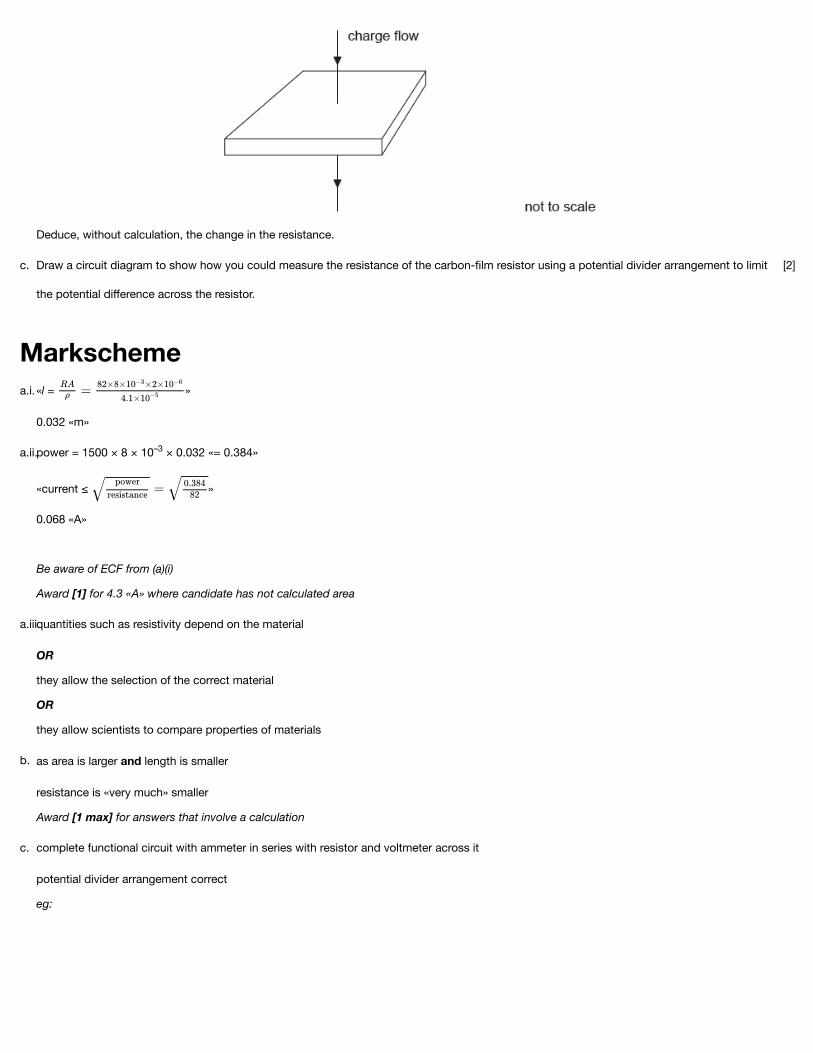
Markscheme
Deduce, without calculation, the change in the resistance.
Draw a circuit diagram to show how you could measure the resistance of the carbon-film resistor using a potential divider arrangement to limit
the potential difference across the resistor.
[2]c.
«l = »
0.032 «m»
a.i.
power = 1500 × 8 × 10 × 0.032 «= 0.384»
«current ≤ »
0.068 «A»
Be aware of ECF from (a)(i)
Award [1] for 4.3 «A» where candidate has not calculated area
–3a.ii.
quantities such as resistivity depend on the material
OR
they allow the selection of the correct material
OR
they allow scientists to compare properties of materials
a.iii.
as area is larger and length is smaller
resistance is «very much» smaller
Award [1 max] for answers that involve a calculation
b.
complete functional circuit with ammeter in series with resistor and voltmeter across it
potential divider arrangement correct
eg:
c.

Examiners report
Markscheme
[N/A]a.i.[N/A]a.ii.[N/A]a.iii.[N/A]b.[N/A]c.
This question is about electric and magnetic fields.
A proton travelling to the right with horizontal speed 1.6×10 ms enters a uniform electric field of strength E. The electric field has magnitude2.0×10 NC and is directed downwards.
4 –1
3 –1
Calculate the magnitude of the electric force acting on the proton when it is in the electric field. [2]a.
A uniform magnetic field is applied in the same region as the electric field. A second proton enters the field region with the same velocity as the
proton in (a). This second proton continues to move horizontally.
(i) Determine the magnitude and direction of the magnetic field.
(ii) An alpha particle enters the field region at the same point as the second proton, moving with the same velocity. Explain whether or not thealpha particle will move in a straight line.
[5]b.
F=qE or 1.6×10 ×2.0×10 ;=3.2×10 (N);
-19 3
-16a.

Examiners report
(i) or ;
or 0.125(T);
directed into the page / OWTTE;
(ii) both electric and magnetic forces double / both forces increase by the same factor / both forces scale with q/charges and cancel;
so straight line followed; (only award if first mark awarded)
or
straight line followed if qE = qvB ⇒E v=B; E, v and B constant (so straight line followed);
b.
This calculation was successfully done by the majority of candidates.a.
bi) The magnitude of the magnetic field was often successfully calculated, but few candidates were able to identify the direction. Most thought that it was in
the opposite direction to the electric field, presumably confusing it with magnetic force.
bii) Many thought that it would carry on in a straight line but this was often based on spurious reasoning.
b.
This question is about the properties of tungsten.
Tungsten is a conductor used as the filament of an electric lamp. The filament of the lamp is surrounded by glass which is an insulator.
Outline, in terms of their atomic structure, the difference between the electrical properties of tungsten and of glass.
[2]a.
A tungsten filament lamp is marked 6.0 V, 15 W.
(i) Show that the resistance of the lamp at its working voltage is 2.4 Ω.
(ii) The length of the filament is 0.35 m and the resistivity of tungsten is 5.6×10 Ω m at its working voltage.
Calculate the cross-sectional area of the tungsten filament.
–7
[3]b.
The diagram shows part of a potential divider circuit used to measure the current-potential difference (I–V) characteristic of the bulb. [2]c.

Markscheme
Examiners report
Draw the complete circuit showing the correct position of the bulb, ammeter and voltmeter.
conduction is due to movement of the free electrons (transferring charge around circuit);
tungsten is a good electrical conductor with large numbers of free electrons;
glass is a poor electrical conductor with few/no free electrons;
a.
(i) or and ;
(ii) ;0.082mm or 8.2×10 m2 -8 2
b.
lamp connected so that pd can be varied;
ammeter in series with lamp and voltmeter
in parallel with lamp; (both needed)
Award [0] if lamp cannot light.
c.
[N/A]a.[N/A]b.[N/A]

c.
Define electric field strength. [2]a.
The diagram shows a pair of horizontal metal plates. Electrons can be deflected vertically using an electric field between the plates.
(i) Label, on the diagram, the polarity of the metal plates which would cause an electronpositioned between the plates to accelerate upwards.
(ii) Draw the shape and direction of the electric field between the plates on the diagram.
(iii) Calculate the force on an electron between the plates when the electric field strength has a value of 2.5 × 10 NC .3 –1
[5]b.
The diagram shows two isolated electrons, X and Y, initially at rest in a vacuum. The initial separation of the electrons is 5.0 mm. The electrons
subsequently move apart in the directions shown.
(i) Show that the initial electric force acting on each electron due to the other electron is approximately 9 × 10 N.
(ii) Calculate the initial acceleration of one electron due to the force in (c)(i).
(iii) Discuss the motion of one electron after it begins to move.
(iv) The diagram shows Y as seen from X, at one instant. Y is moving into the plane of the paper. For this instant, draw on the diagram the shapeand direction of the magnetic field produced by Y.
–24
[8]c.
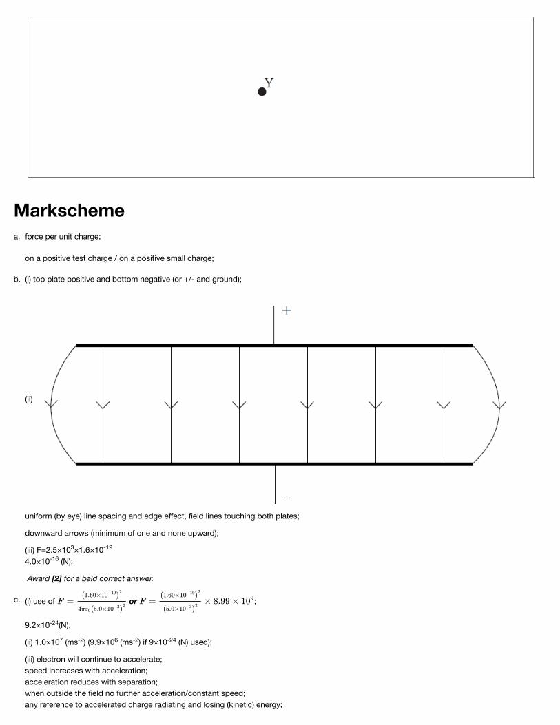
Markschemeforce per unit charge;
on a positive test charge / on a positive small charge;
a.
(i) top plate positive and bottom negative (or +/- and ground);
(ii)
uniform (by eye) line spacing and edge effect, field lines touching both plates;
downward arrows (minimum of one and none upward);
(iii) F=2.5×10 ×1.6×104.0×10 (N);
Award [2] for a bald correct answer.
3 -19
-16
b.
(i) use of or ;
9.2×10 (N);
(ii) 1.0×10 (ms ) (9.9×10 (ms ) if 9×10 (N) used);
(iii) electron will continue to accelerate;speed increases with acceleration;acceleration reduces with separation;when outside the field no further acceleration/constant speed;any reference to accelerated charge radiating and losing (kinetic) energy;
-24
7 -2 6 -2 -24
c.

Examiners report
(iv) minimum of two concentric circles centred on Y;anti-clockwise;
(i) As this is worth two marks, candidates should see the signal that force per unit charge is unlikely to gain full marks; and so it proved. Although a
mark was available for saying this there needed to be a reference to the charge being a positive test charge.
a.
(i) G2 comments that the term ‘polarity’ was confusing to candidates proved to be unfounded and nearly all candidates marked in a positive and
negative terminal – although the actual polarity was often incorrect.
(ii) With error carried forwards, the direction of the field was often correct but the drawing often was below an acceptable standard with line of forcenot bridging the plates, being very unevenly spaced and having no edge effect.
(iii) This calculation was almost invariably very well done.
b.
(i) In another ‘show that’ question it was expected that candidates would use Coulombs law and the data value for the electronic charge to give a
value of more than one digit; often this was not the case but otherwise this was generally well done
(ii) Most candidates used their value for the force (or 9 x 10-24 N) and the mass of the electron on the data sheet to calculate a correct value for the
acceleration.
(iii) This was an unusual opportunity for candidates to use Newton’s laws and many did say that the acceleration would decrease with distance. Too
often they incorrectly believed that this meant that the electron would slow down – it continues to accelerate but at an ever decreasing rate.
(iv) Clearly, this part represented a simplification of a complex situation but as set up was not beyond the skills of most of the candidates. The
electron represents an instant in which a conventional current would leave the page and the field at this instant would be that of concentric circles
with an anti-clockwise (counter-clockwise) direction. Many candidates did draw this but diagrams were too frequently hurriedly drawn and of a
poor standard.
c.
Part 2 Electrical resistance
A resistor of resistance 1.5Ω is made from copper wire of radius 0.18mm. The resistivity of copper is 1.7×10 Ωm. Determine the length of
copper wire used to make the resistor.
–8 [2]a.
The manufacturer of the resistor in (a) guarantees that the resistance is within 10% of 1.5Ω, provided that the power dissipation in the resistor
does not exceed 1.0W.
(i) Suggest why the resistance of the resistor might be greater than 1.65Ω if the power dissipation in the resistor is greater than 1.0W.
(ii) Show that, for a power dissipation of 1.0W, the current in a resistor of resistance 1.5Ω is 0.82A.
[6]b.

Markscheme
Examiners report
(iii) The 1.5Ω resistor is connected in series with a variable resistor and battery of emf 6.0V and internal resistance 1.8Ω.
Estimate the resistance R of the variable resistor that will limit the current to 0.82A.
use of ; } (allow if correct substitution seen – watch for use of circumference in place of area)
;
a.
(i) the resistance of a conductor/copper/metal increases with increasing temperature;
increased power (dissipation) leads to higher temperature in the resistor/ resistor heating up;
(ii) ;
(=0.82A)
Allow working using 0.82A to show that power is 1.0086W, in this case final answer must be to 2 sig fig or better.
(iii) total resistance = [R+3.3];
6.0=0.82[R+3.3];
to give R=4.0Ω; (allow use of 1.65Ω leading to 3.9Ω)
or
total resistance in circuit = ;
internal resistance+fixed resistance=3.3Ω;
to give R=4.0Ω;
b.
a. b.
This question is about motion in a magnetic field.
An electron, that has been accelerated from rest by a potential difference of 250 V, enters a region of magnetic field of strength 0.12 T that is directedinto the plane of the page.

Markscheme
The electron’s path while in the region of magnetic field is a quarter circle. Show that the
(i) speed of the electron after acceleration is 9.4×10 ms .
(ii) radius of the path is 4.5×10 m.
6 −1
−4
[4]a.
The diagram below shows the momentum of the electron as it enters and leaves the region of magnetic field. The magnitude of the initial
momentum and of the final momentum is 8.6×10 Ns.
(i) On the diagram above, draw an arrow to indicate the vector representing the change in the momentum of the electron.
(ii) Show that the magnitude of the change in the momentum of the electron is 1.2×10 Ns.
(iii) The time the electron spends in the region of magnetic field is 7.5 ×10 s. Estimate the magnitude of the average force on the electron.
−24
−23
−11
[3]b.
(i) ;
;
=9.4×10 ms6 −1
a.

Examiners report
(ii) evB=m ;
;
=4.5×10 m−4
(i) vector as shown;
(ii) ;=1.2×10 Ns
(iii) ;
−23
b.
[N/A]a.[N/A]b.
This question is in two parts. Part 1 is about a lighting system. Part 2 is about a satellite.
Part 1 Lighting system
State Ohm’s law. [1]a.
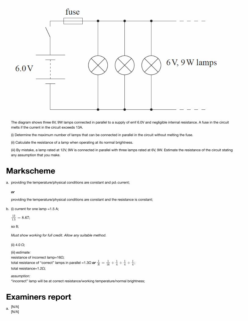
A lighting system is designed so that additional lamps can be added in parallel. [8]b.
Markscheme
Examiners report
The diagram shows three 6V, 9W lamps connected in parallel to a supply of emf 6.0V and negligible internal resistance. A fuse in the circuitmelts if the current in the circuit exceeds 13A.
(i) Determine the maximum number of lamps that can be connected in parallel in the circuit without melting the fuse.
(ii) Calculate the resistance of a lamp when operating at its normal brightness.
(iii) By mistake, a lamp rated at 12V, 9W is connected in parallel with three lamps rated at 6V, 9W. Estimate the resistance of the circuit statingany assumption that you make.
providing the temperature/physical conditions are constant and pd∝current;
or
providing the temperature/physical conditions are constant and the resistance is constant;
a.
(i) current for one lamp =1.5 A;
;
so 8;
Must show working for full credit. Allow any suitable method.
(ii) 4.0 Ω;
(iii) estimate:resistance of incorrect lamp=16Ω;total resistance of “correct” lamps in parallel =1.3Ω or ;total resistance=1.2Ω;
assumption:“incorrect” lamp will be at correct resistance/working temperature/normal brightness;
b.
[N/A]a.[N/A]

Markscheme
b.
A possible decay of a lambda particle ( ) is shown by the Feynman diagram.
State the quark structures of a meson and a baryon. [2]a.
Explain which interaction is responsible for this decay. [2]b.i.
Draw arrow heads on the lines representing and d in the . [1]b.ii.
Identify the exchange particle in this decay. [1]b.iii.
Outline one benefit of international cooperation in the construction or use of high-energy particle accelerators. [1]c.
Meson: quark-antiquark pair
Baryon: 3 quarks
a.
Alternative 1
strange quark changes «flavour» to an up quark
changes in quarks/strangeness happen only by the weak interaction
Alternative 2
Strangeness is not conserved in this decay «because the strange quark changes to an up quark»
Strangeness is not conserved during the weak interaction
b.i.

Examiners report
Do not allow a bald answer of weak interaction.
arrows drawn in the direction shown
Both needed for [1] mark.
b.ii.
W
Do not allow W or W .
−
+
b.iii.
it lowers the cost to individual nations, as the costs are shared
international co-operation leads to international understanding OR historical example of co-operation OR co-operation always allows science toproceed
large quantities of data are produced that are more than one institution/research group can handle co-operation allows effective analysis
Any one.
c.
[N/A]a.[N/A]b.i.[N/A]b.ii.[N/A]b.iii.[N/A]c.
A cable consisting of many copper wires is used to transfer electrical energy from a generator to an electrical load. The copper wires are protected by
an insulator.
The cable consists of 32 copper wires each of length 35 km. Each wire has a resistance of 64 Ω. The resistivity of copper is 1.7 x 10 Ω m.–8

Markscheme
Examiners report
The copper wires and insulator are both exposed to an electric field. Discuss, with reference to charge carriers, why there is a significant electric
current only in the copper wires.
[3]a.
Calculate the radius of each wire. [2]b.i.
There is a current of 730 A in the cable. Show that the power loss in 1 m of the cable is about 30 W. [2]b.ii.
When the current is switched on in the cable the initial rate of rise of temperature of the cable is 35 mK s . The specific heat capacity of copper
is 390 J kg K . Determine the mass of a length of one metre of the cable.
–1
–1 –1
[2]b.iii.
when an electric field is applied to any material «using a cell etc» it acts to accelerate any free electrons
electrons are the charge carriers «in copper»
Accept “free/valence/delocalised electrons”.
metals/copper have many free electrons whereas insulators have few/no free electrons/charge carriers
a.
area = «= 9.3 x 10 m »–6 2b.i.
«resistance of cable = 2Ω»
power dissipated in cable = 730 x 2 «= 1.07 MW»
power loss per meter or 30.6 «W m »
Allow [2] for a solution where the resistance per unit metre is calculated using resistivity and answer to (b)(i) (resistance per unit length of cable =5.7x 10 m)
2
–1
–5
b.ii.
30 = m x 390 x 3.5 x 10
2.2 k«g»
Correct answer only.
–2b.iii.
[N/A]a.[N/A]b.i.[N/A]b.ii.[N/A]b.iii.
This question is about magnetic fields.
A long straight vertical conductor carries an electric current. The conductor passes through a hole in a horizontal piece of paper.

Markscheme
State how a magnetic field arises. [1]a.
On the diagram below, sketch the magnetic field pattern around the long straight current-carrying conductor. The direction of the current is into
the plane of the paper.
[2]b.
The long straight conductor is formed into a coil consisting of two separate turns, X and Y. The coil hangs with its axis vertical.
Assume that the turns of the coil each behave as a long straight conductor.
(i) Explain why, when there is a current in the coil, the separation of X and Y decreases.
(ii) The current in the coil is 15 A and the circumference of one turn is 0.48m. In order to restore X and Y to their original separation, a mass of2.8×10 kg is suspended from turn Y. Estimate the magnetic field strength at X due to Y.–4
[5]c.

Examiners report
(electric current means) movement of charge;
Do not allow references to current alone – this is in the question.
Do not allow references to charges repelling.
a.
at least two concentric circles;
with clockwise direction indicated;
b.
(i) each turn subject to the magnetic field of the other / field patterns for individual turns combine;
force shown to be attractive by use of direction rule/ by consideration of field pattern / OWTTE; { (can be shown diagrammatically)
(ii) F=(0.280×10 ×9.81=)2.75×10 N; or correct substitution 2.75×10 =B×(15)×0.48;
;
–3 –3
–3
c.
[N/A]a.[N/A]b.[N/A]c.
The graph shows how current I varies with potential difference V for a resistor R and a non-ohmic component T.
(i) State how the resistance of T varies with the current going through T.
(ii) Deduce, without a numerical calculation, whether R or T has the greater resistance at I=0.40 A.
[3]a.
Components R and T are placed in a circuit. Both meters are ideal. [3]b.

Markscheme
Slider Z of the potentiometer is moved from Y to X.
(i) State what happens to the magnitude of the current in the ammeter.
(ii) Estimate, with an explanation, the voltmeter reading when the ammeter reads 0.20 A.
i
R decreases with increasing I
OR
R and I are negatively correlated
Must see reference to direction of change of current in first alternative.Do not allow “inverse proportionality”. May be worth noting any marks on graph relating to 7bii
ii
at 0.4 A: V > V or V = 5.6 V and V = 5.3 V
Award [0] for a bald correct answer without deduction or with incorrect reasoning.
Ignore any references to graph gradients.
so R >R because V = IR / V∝ R «and I same for both»
Both elements must be present for MP2 to be awarded.
T
T
R T R T
R T
a.
i
decreasesOR
becomes zero at X
ii
realization that V is the same for R and TOR
identifies that currents are 0.14 A and 0.06 A
Award [0] if pds 2.8 V and 3.7 V or 1.4 V and 2.6V are used in any way. Otherwise award [1 max] for a bald correct answer. Explanation expected.
2 V = 2 V OR 2.0 V
b.

Examiners report[N/A]a.[N/A]b.
In an experiment a student constructs the circuit shown in the diagram. The ammeter and the voltmeter are assumed to be ideal.
State what is meant by an ideal voltmeter. [1]a.
The student adjusts the variable resistor and takes readings from the ammeter and voltmeter. The graph shows the variation of the voltmeter
reading V with the ammeter reading I.
[3]b.

Use the graph to determine
(i) the electromotive force (emf) of the cell.
(ii) the internal resistance of the cell.
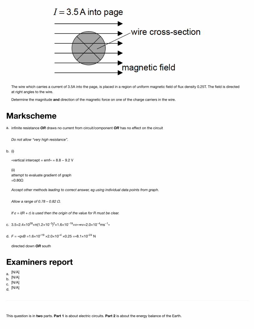
A connecting wire in the circuit has a radius of 1.2mm and the current in it is 3.5A. The number of electrons per unit volume of the wire is
2.4×10 m . Show that the drift speed of the electrons in the wire is 2.0×10 ms .28 −3 −4 −1
[1]c.
The diagram shows a cross-sectional view of the connecting wire in (c). [2]d.
Markscheme
Examiners report
The wire which carries a current of 3.5A into the page, is placed in a region of uniform magnetic field of flux density 0.25T. The field is directedat right angles to the wire.
Determine the magnitude and direction of the magnetic force on one of the charge carriers in the wire.
infinite resistance OR draws no current from circuit/component OR has no effect on the circuit
Do not allow “very high resistance”.
a.
(i)
«vertical intercept = emf» = 8.8 − 9.2 V
(ii)attempt to evaluate gradient of graph=0.80Ω
Accept other methods leading to correct answer, eg using individual data points from graph.
Allow a range of 0.78 – 0.82 Ω.
If ε = I(R + r) is used then the origin of the value for R must be clear.
b.
3.5=2.4×10 ×π(1.2×10 ) ×1.6×10 ×v« v=2.0×10 ms »28 −3 2 −19 −4 −1c.
F = «qvB =1.6×10 ×2.0×10 ×0.25 =»8.1×10 N
directed down OR south
–19 –4 –24d.
[N/A]a.[N/A]b.[N/A]c.[N/A]d.
This question is in two parts. Part 1 is about electric circuits. Part 2 is about the energy balance of the Earth.

Part 1 Electric circuits
Define
(i) electromotive force (emf ) of a battery.
(ii) electrical resistance of a conductor.
[2]a.
A battery of emf ε and negligible internal resistance is connected in series to two resistors. The current in the circuit is I.
(i) State an equation giving the total power delivered by the battery.
(ii) The potential difference across resistor R is V and that across resistor R is V . Using the law of the conservation of energy, deduce theequation below.
ε =V +V
1 1 2 2
1 2
[3]b.
The graph shows the I-V characteristics of two conductors, X and Y.
On the axes below, sketch graphs to show the variation with potential difference V of the resistance of conductor X (label this graph X) andconductor Y (label this graph Y). You do not need to put any numbers on the vertical axis.
[3]c.

Markscheme
The conductors in (c) are connected in series to a battery of emf ε and negligible internal resistance.
The power dissipated in each of the two resistors is the same.
Using the graph given in (c),
(i) determine the emf of the battery.
(ii) calculate the total power dissipated in the circuit.
[4]d.
(i) the work done per unit charge in moving a quantity of charge completely around a circuit / the power delivered per unit current / work done per
unit charge made available by a source;
(ii) the ratio of the voltage (across) to the current in the conductor;
a.
(i) emf × current;
(ii) total power is V I +V I;equating with EI to get result;or
total energy delivered by battery is EQ;equate with energy in each resistor V Q +V Q;
1 2
1 2
b.
graph X: horizontal straight line;
graph Y: starts lower than graph X;
rises (as straight line or curve) and intersects at 4.0 V;
c.

Examiners report
Do not pay attention to numbers on the vertical axis.
(i) realization that the voltage must be 4.0 V across each resistor;
and so emf is 8.0 V;
(ii) power in each resistor = 3.2W;and so total power is 6.4 W;or
current is 0.80 A;so total power is 8.0×0.80 = 6.4W;
d.
[N/A]a.[N/A]b.[N/A]c.[N/A]d.
Part 2 Electric current and resistance
The graph below shows how the current I in a tungsten filament lamp varies with potential difference V across the lamp.

Markscheme
(i) Define the electrical resistance of a component.
(ii) Explain whether or not the filament obeys Ohm’s law.
[3]a.
(i) Calculate the resistance of the filament lamp when the potential difference across it is 2.8 V.
(ii) The length of the filament in a lamp is 0.40 m. The resistivity of tungsten when the potential difference across it is 2.8 V is 5.8×10 Ω m.Calculate the radius of the filament.
–7
[5]b.
Two identical filament lamps are connected in series with a cell of emf 6.0 V and negligible internal resistance. Using the graph on page 26,
calculate the total power dissipated in the circuit.
[2]c.

Examiners report
(i) ;
Award [0] for simple statement of voltage divided by current
(ii) Ohm’s law states that voltage is (directly) proportional to current or /resistance is a constant;
graph not linear/gradient not constant so Ohm’s law not obeyed / calculation of at two points showing that they are different;Award [0] for bald statement of Ohm’s law not obeyed.
a.
(i) (from graph, when V = 2.8 V,) I = 0.33 A; (accept answers in range 0.32 to 0.34 A)
; (accept answers in range 8.2 to 8.8 Ω)
(ii) ;
(accept answers in range 2.6 to 2.8×10 )
seen/used;=9.3×10 m; (accept answers in range 9.2 to 9.5×10 )
–8
-5 –5
b.
each lamp has a potential difference of 3.0 V so current equals 0.35 A;
(accept answers in range 0.34 to 0.35 A)
2.1 W; (accept answers in range 2.0 to 2.1 W)
Award [1] for answers that use voltage 6.0 V with current 0.52 A to get P=3.1W.
c.
[N/A]a.[N/A]b.[N/A]c.
This question is in two parts. Part 1 is about electric fields and radioactive decay. Part 2 is about change of phase.
Part 1 Electric fields and radioactive decay
Part 2 Change of phase
Define electric field strength. [2]a.
A simple model of the proton is that of a sphere of radius 1.0×10 m with charge concentrated at the centre of the sphere. Estimate the
magnitude of the field strength at the surface of the proton.
–15 [2]b.
Protons travelling with a speed of 3.9×10 ms enter the region between two charged parallel plates X and Y. Plate X is positively charged and
plate Y is connected to earth.
6 –1 [4]c.

A uniform magnetic field also exists in the region between the plates. The direction of the field is such that the protons pass between the plateswithout deflection.
(i) State the direction of the magnetic field.
(ii) The magnitude of the magnetic field strength is 2.3×10 T. Determine the magnitude of the electric field strength between the plates, statingan appropriate unit for your answer.
–4
Protons can be produced by the bombardment of nitrogen-14 nuclei with alpha particles. The nuclear reaction equation for this process is given
below.
Identify the proton number and nucleon number for the nucleus X.
[1]d.
The following data are available for the reaction in (d).
Rest mass of nitrogen-14 nucleus =14.0031 uRest mass of alpha particle =4.0026 uRest mass of X nucleus =16.9991 uRest mass of proton =1.0073 u
Show that the minimum kinetic energy that the alpha particle must have in order for the reaction to take place is about 0.7 Me V.
[3]e.
A nucleus of another isotope of the element X in (d) decays with a half-life to a nucleus of an isotope of fluorine-19 (F-19).
(i) Define the terms isotope and half-life.
(ii) Using the axes below, sketch a graph to show how the number of atoms N in a sample of X varies with time t, from t=0 to . There are
N atoms in the sample at t=0.0
[5]f.

Markscheme
Water at constant pressure boils at constant temperature. Outline, in terms of the energy of the molecules, the reason for this. [2]g.
In an experiment to measure the specific latent heat of vaporization of water, steam at 100°C was passed into water in an insulated container.
The following data are available.
Initial mass of water in container = 0.300kgFinal mass of water in container = 0.312kgInitial temperature of water in container = 15.2°CFinal temperature of water in container = 34.6°CSpecific heat capacity of water = 4.18×10 Jkg K
Show that the data give a value of about 1.8×10 Jkg for the specific latent heat of vaporization L of water.
3 –1 –1
6 –1
[4]h.
Explain why, other than measurement or calculation error, the accepted value of L is greater than that given in (h). [2]i.
the force exerted per unit charge;
on a positive small/test charge;
a.
;
or Vm ;-1
b.
(i) into the (plane of the) paper;
(ii) Ee=Bev or E=Bv;
=(2.3×10 ×3.9×10 =)900/897;
NC or Vm ;
-4 6
-1 -1
c.
proton number: 8
nucleon number: 17
(both needed)
d.
16.9991u+1.0073u-[14.0031u+4.0026u];
=-7.00×10 ;
7.000×10 ×931.5=0.6521MeV;
(∼0.7MeV)
-4
-4
e.
(i) isotope:
same proton number/element/number of protons and different number of neutrons/nucleon number/neutron number; } (both needed)
half-life:time for the activity (of a radioactive sample) to fall by half its original value / time for half the radioactive/unstable nuclei/atoms (in a sample) todecay;
f.

(ii)
(approximately) exponential shape;minimum of three half lives shown;graph correct at ;
temperature is a measure of the (average) kinetic energy of the molecules;
at the boiling point, energy supplied (does not increase the kinetic energy) but (only) increases the potential energy of the molecules/goes into
increasing the separation of the molecules/breaking one molecule from another / OWTTE;
g.
(energy gained by cold water is) 0.300×4180×[34.6-15.2] / 24327;
(energy lost by cooling water is) 0.012×4180×[100-34.6] / 3280;
(energy lost by condensing steam is) 0.012L;
1.75×10 (Jkg )/
;
Award [4] for 1.75×10 (Jkg ).Award [2 max] for an answer that ignores cooling of condensed steam.
6 -1
6 -1
h.
some of the energy (of the condensing steam) is lost to the surroundings;
so less energy available to be absorbed by water / rise in temperature of the water would be greater if no energy lost;
i.

Examiners report[N/A]a.[N/A]b.[N/A]c.[N/A]d.[N/A]e.[N/A]f.[N/A]g.[N/A]h.[N/A]i.
A company designs a spring system for loading ice blocks onto a truck. The ice block is placed in a holder H in front of the spring and an electric
motor compresses the spring by pushing H to the left. When the spring is released the ice block is accelerated towards a
ramp ABC. When the spring is fully decompressed, the ice block loses contact with the spring at A. The mass of the ice block is 55 kg.
Assume that the surface of the ramp is frictionless and that the masses of the spring and the holder are negligible compared to the mass of the iceblock.
(i) The block arrives at C with a speed of 0.90ms . Show that the elastic energy stored in the spring is 670J.
(ii) Calculate the speed of the block at A.
−1 [4]a.
Describe the motion of the block
(i) from A to B with reference to Newton's first law.
(ii) from B to C with reference to Newton's second law.
[3]b.
On the axes, sketch a graph to show how the displacement of the block varies with time from A to C. (You do not have to put numbers on the
axes.)
[2]c.

Markscheme
The spring decompression takes 0.42s. Determine the average force that the spring exerts on the block. [2]d.
The electric motor is connected to a source of potential difference 120V and draws a current of 6.8A. The motor takes 1.5s to compress the
spring.
Estimate the efficiency of the motor.
[2]e.
(i)
OR
«E =»E +E
OR
669 J «E = 669 ≈ 670J»
Award [1 max] for use of g=10Nkg , gives 682 J.
(ii)
If 682J used, answer is 5.0ms .
el P K
el
–1
–1
a.
(i)
no force/friction on the block, hence constant motion/velocity/speed
(ii)
force acts on block OR gravity/component of weight pulls down slope
velocity/speed decreases OR it is slowing down OR it decelerates
b.

Examiners report
Do not allow a bald statement of “N2” or “F = ma” for MP1.
Treat references to energy as neutral.
straight line through origin for at least one-third of the total length of time axis covered by candidate line
followed by curve with decreasing positive gradient
Ignore any attempt to include motion before A.
Gradient of curve must always be less than that of straight line.
c.
F=642≈640N
Allow ECF from (a)(ii).
d.
«energy supplied by motor =» 120 × 6.8 × 1.5 or 1224 J
OR
«power supplied by motor =» 120 × 6.8 or 816 W
e = 0.55 or 0.547 or 55% or 54.7%
Allow ECF from earlier results.
e.
[N/A]a.[N/A]b.[N/A]c.[N/A]d.[N/A]e.
This question is in two parts. Part 1 is about simple harmonic motion (SHM) and waves. Part 2 is about voltage–current (V–I) characteristics.
Part 1 Simple harmonic motion (SHM) and waves
Part 2 Voltage–current (V–I) characteristics

The graph shows the voltage–current (V–I) characteristics, at constant temperature, of two electrical components X and Y.
A particle P moves with simple harmonic motion. State, with reference to the motion of P, what is meant by simple harmonic motion. [2]a.
Use the graph opposite to determine for the motion of P the
(i) period.
(ii) amplitude.
(iii) displacement of P from equilibrium at t=0.2s.
[7]b.
The particle P in (b) is a particle in medium M through which a transverse wave is travelling.
(i) Describe, in terms of energy propagation, what is meant by a transverse wave.
(ii) The speed of the wave through the medium is 0.40ms . Calculate, using your answer to (b)(i), the wavelength of the wave.
(iii) The wave travels into another medium M . The refractive index of M relative to M is 1.8. Calculate the wavelength of the wave in M .
1
–1
2 2 1 2
[5]c.
Outline, with reference to the graph and to Ohm’s law, whether or not each component is ohmic. [3]d.
Components X and Y are connected in parallel. The parallel combination is then connected in series with a variable resistor R and a cell of emf
8.0V and negligible internal resistance.
[8]e.

Markscheme
The resistance of R is adjusted until the currents in X and Y are equal.
(i) Using the graph, calculate the resistance of the parallel combination of X and Y.
(ii) Using your answer to (e)(i), determine the resistance of R.
(iii) Determine the power delivered by the cell to the circuit.
the acceleration (of a particle/P) is (directly) proportional to displacement;
and is directed towards equilibrium/in the opposite direction to displacement;
Do not accept “directed towards the centre”.
a.
(i) 0.30 s;
(ii) max velocity=0.74(±0.02)ms ;recognize max velocity=ωx ;
;
;
or
identifies displacement with area;uses one quarter of a cycle;answer in the range of 30 to 40 mm;answer in the range of 33 to 37 mm;
(iii) ;use to get x=1.7(±0.2)×10 m
or
recognition that x=x cosωt;
;
−1
0
-2
0
b.
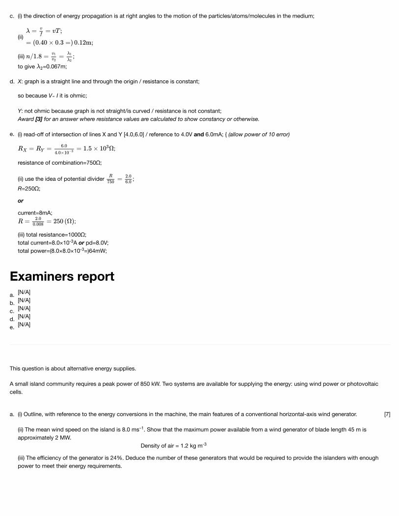
Examiners report
(i) the direction of energy propagation is at right angles to the motion of the particles/atoms/molecules in the medium;
(ii)
(iii) ;to give =0.067m;
c.
X: graph is a straight line and through the origin / resistance is constant;
so because V∝ I it is ohmic;
Y: not ohmic because graph is not straight/is curved / resistance is not constant;Award [3] for an answer where resistance values are calculated to show constancy or otherwise.
d.
(i) read-off of intersection of lines X and Y [4.0,6.0] / reference to 4.0V and 6.0mA; { (allow power of 10 error)
;
resistance of combination=750Ω;
(ii) use the idea of potential divider ;R=250Ω;
or
current=8mA;;
(iii) total resistance=1000Ω;total current=8.0×10 A or pd=8.0V;total power=(8.0×8.0×10 =)64mW;
-3
-3
e.
[N/A]a.[N/A]b.[N/A]c.[N/A]d.[N/A]e.
This question is about alternative energy supplies.
A small island community requires a peak power of 850 kW. Two systems are available for supplying the energy: using wind power or photovoltaiccells.
(i) Outline, with reference to the energy conversions in the machine, the main features of a conventional horizontal-axis wind generator.
(ii) The mean wind speed on the island is 8.0 ms . Show that the maximum power available from a wind generator of blade length 45 m isapproximately 2 MW. Density of air = 1.2 kg m
(iii) The efficiency of the generator is 24%. Deduce the number of these generators that would be required to provide the islanders with enoughpower to meet their energy requirements.
–1
-3
[7]a.

The graph below shows how the wind speed varies with height above the land and above the sea.
(i) Suggest why, for any given height, the mean wind speed above the sea is greater than the mean wind speed above the land.
(ii) There is a choice of mounting the wind generators either 60m above the land or 60m above the sea.
Calculate the ratio
at a height of 60m.
[3]b.
Distinguish between photovoltaic cells and solar heating panels. [2]c.
The diagram shows 12 photovoltaic cells connected in series and in parallel to form a module to provide electrical power.
[8]d.

Markscheme
Each cell in the module has an emf of 0.75V and an internal resistance of 1.8Ω.
(i) Calculate the emf of the module.
(ii) Determine the internal resistance of the module.
(iii) The diagram below shows the module connected to a load resistor of resistance 2.2Ω.
Calculate the power dissipated in the load resistor.
(iv) Discuss the benefits of having cells combined in series and parallel within the module.
The intensity of the Sun’s radiation at the position of the Earth’s orbit (the solar constant) is approximately 1.4×10 Wm .
(i) Explain why the average solar power per square metre arriving at the Earth is 3.5×10 W.
(ii) State why the solar constant is an approximate value.
(iii) Photovoltaic cells are approximately 20% efficient. Estimate the minimum area needed to supply an average power of 850kW over a 24 hourperiod.
3 –2
2
[5]e.
(i) mention of blades/propeller and turbine/generator/dynamo;
kinetic energy of wind → kinetic energy of turbine;
(rotational) kinetic energy → electricity/electrical energy;
Award [1 max] for statement of (unqualified) kinetic energy to electrical energy
(ii) A(=πr )=6.4×10 (m );(P=)1.95 MW;
(iii) 0.24×1.95MW (=0.47 MW/0.48 MW); (0.47 MW = 470 kW thus) two generators would meet the maximum demand;Allow only two generators for the second mark. Do not accept fractional generators.
2 3 2
a.

Examiners report
(i) sea is smoother (does not interrupt wind flow) / no obstacles on sea / less friction / less turbulence (vice versa for land) / OWTTE; Allow named
obstacles, eg trees/buildings/hills, etc.
(ii) ;
;
Award [1 max] for 1.9 due to inverted ratio.
b.
photovoltaic cells generate emf/electricity;
solar panels generate thermal energy/heat / OWTTE;
c.
(i) emf=3.0 (V);
(ii) series combination of resistance=7.2(Ω);use of parallel resistance formula; 2.4(Ω);Award [3] for a bald correct answer
(iii) attempted use of IV, I R or ;0.94 (W);Allow ECF from (d)(i) and (d)(ii).Must see values substituted to gain first mark as compensation.
(iv) (series) increases the total emf/voltage;(parallel) increases the current/decreases internal resistance/ensures some power if single cell fails / OWTTE;
2
d.
(i) the solar radiation is captured by a disc of area πR where R is the radius of the Earth;
but is distributed (when averaged) over the entire Earth’s surface which has an area four times as large;
or
rays make an angle θ with area of Earth’s half-sphere and so average intensity is proportional to average of cos θ i.e. ;there is an additional factor of due to the other half of the sphere;
(ii) variation of solar emission / Earth’s orbit is elliptical/not quite circular;
(iii) input power needed =(5×850(kW)=) 4.25×10 (W);
;
Award [2] for a bald correct answer.
2
2
6
e.
(i) Many did not mention the kinetic energy of the wind (often referring to ‘wind energy’). All types of kinetic energy were referred to as ‘mechanical’
energy by many candidates. The general structure of this type of wind generator was generally well-known.
(ii) This part was generally well answered with those candidates completing the area calculation usually going on to gain both marks.
(iii) Again, this was well answered with nearly all candidates recognising that is not possible to have fractional generators and, therefore, rounding
up their answers to 2 from the 1.7 calculation.
a.

(i) Most candidates were able to suggest why the winds above the sea are higher than those above the land for the same height. A minority
incorrectly answered this in terms of convection currents and sea versus land temperatures.
(ii) Nearly all candidates were able to correctly read the two values from the graph and a slight majority of these went on to correctly cube the ratio.
b.
Most candidates knew the difference between photovoltaic cells and solar heating panels. A minority believed that both would normally produce
electricity.
c.
(i) This was not well known and many candidates simply added the emfs to give a value of 9.0 V rather than the correct 3.0 V.
(ii) Nearly all candidates correctly calculated the resistance of the series portions of the modules but there were frequent errors in combining these
to find the total resistance – with the parallel formula often being incorrectly written in shorthand
(iii) Although many candidates recognised how they should use the power formula, very few were able to used the correct resistance and the
correct voltage.
(iv) Many candidates knew that a failing cell would still allow current in other parallel branches, but few explained that the series combination
increased the emf and the parallel combination increased the current in a module.
d.
(i) A significant minority of candidates insisted that the reduction in the Sun’s intensity was due to radiation reflected from atmosphere. Few went
on to do the calculation to support their answer but there were a small number of very good answers to this part.
(ii) Here again, many mentioned radiation reflected by atmosphere rather than variations in solar emissions or the non-circularity of Earth’s orbit.
(iii) This part was generally poorly done. The ‘24-hour period’ confused many candidates and few were able to follow the argument through to a
logical conclusion.
e.
This question is in two parts. Part 1 is about momentum. Part 2 is about electric point charges.
Part 1 Momentum
Part 2 Electric point charges
State the law of conservation of linear momentum. [2]a.
A toy car crashes into a wall and rebounds at right angles to the wall, as shown in the plan view. [9]b.

The graph shows the variation with time of the force acting on the car due to the wall during the collision.
The kinetic energy of the car is unchanged after the collision. The mass of the car is 0.80 kg.
(i) Determine the initial momentum of the car.
(ii) Estimate the average acceleration of the car before it rebounds.
(iii) On the axes, draw a graph to show how the momentum of the car varies during the impact. You are not required to give values on the y-axis.

Two identical toy cars, A and B are dropped from the same height onto a solid floor without rebounding. Car A is unprotected whilst car B is in a
box with protective packaging around the toy. Explain why car B is less likely to be damaged when dropped.
[4]c.
Define electric field strength at a point in an electric field. [2]d.
Six point charges of equal magnitude Q are held at the corners of a hexagon with the signs of the charges as shown. Each side of the hexagon
has a length a.
[8]e.

Markscheme
P is at the centre of the hexagon.
(i) Show, using Coulomb’s law, that the magnitude of the electric field strength at point P due to one of the point charges is
(ii) On the diagram, draw arrows to represent the direction of the field at P due to point charge A (label this direction A) and point charge B (labelthis direction B).
(iii) The magnitude of Q is 3.2 μC and length a is 0.15 m. Determine the magnitude and the direction of the electric field strength at point P dueto all six charges.
total momentum does not change/is constant; } (do not allow “momentum is conserved”)
provided external force is zero / no external forces / isolated system;
a.
(i) clear attempt to calculate area under graph;
initial momentum is half change in momentum;
Award [2 max] for calculation of total change (1.92kg ms )
(ii) initial speed ;
or ;–15(ms ); (must see negative sign or a comment that this is a deceleration)
or
average force =12 N;uses F=0.8×a ;
–1
–2
b.

–15(ms ); (must see negative sign or a comment that this is a deceleration)Award [3] for a bald correct answer.Other solution methods involving different kinematic equations are possible.
(iii) goes through t=0.08s and from negative momentum to positive / positive momentum to negative;constant sign of gradient throughout;curve as shown;Award marks for diagram as shown.
–2
impulse is the same/similar in both cases / momentum change is same;
impulse is force × time / force is rate of change of momentum;
time to come to rest is longer for car B;
force experienced by car B is less (so less likely to be damaged);
c.
electric force per unit charge;
acting on a small/point positive (test) charge;
d.
(i) states Coulomb’s law as or
states explicitly q=1;
states r=a;
e.

Examiners report
(ii)
arrow labelled A pointing to lower right charge;arrow labelled B point to lower left charge;Arrows can be anywhere on diagram.
(iii) overall force is due to +Q top left and -Q bottom right / top right and bottom left and centre charges all cancel; } (can be seen on diagram)force is therefore ;
2.6×10⁶ (N C ) ;towards bottom right charge; (allow clear arrow on diagram showing direction)
-1
[N/A]a.[N/A]b.[N/A]c.[N/A]d.[N/A]e.
This question is in two parts. Part 1 is about simple harmonic motion (SHM). Part 2 is about current electricity.
Part 1 Simple harmonic motion (SHM)
An object is placed on a frictionless surface. The object is attached by a spring fixed at one end and oscillates at the end of the spring with simpleharmonic motion (SHM).

The tension F in the spring is given by F = k x where x is the extension of the spring and k is a constant.
Part 2 Current electricity
Show that . [2]a.
One cycle of the variation of displacement with time is shown for two separate mass–spring systems, A and B.
(i) Calculate the frequency of the oscillation of A.
(ii) The springs used in A and B are identical. Show that the mass in A is equal to the mass in B.
[3]b.
The graph shows the variation of the potential energy of A with displacement. [5]c.
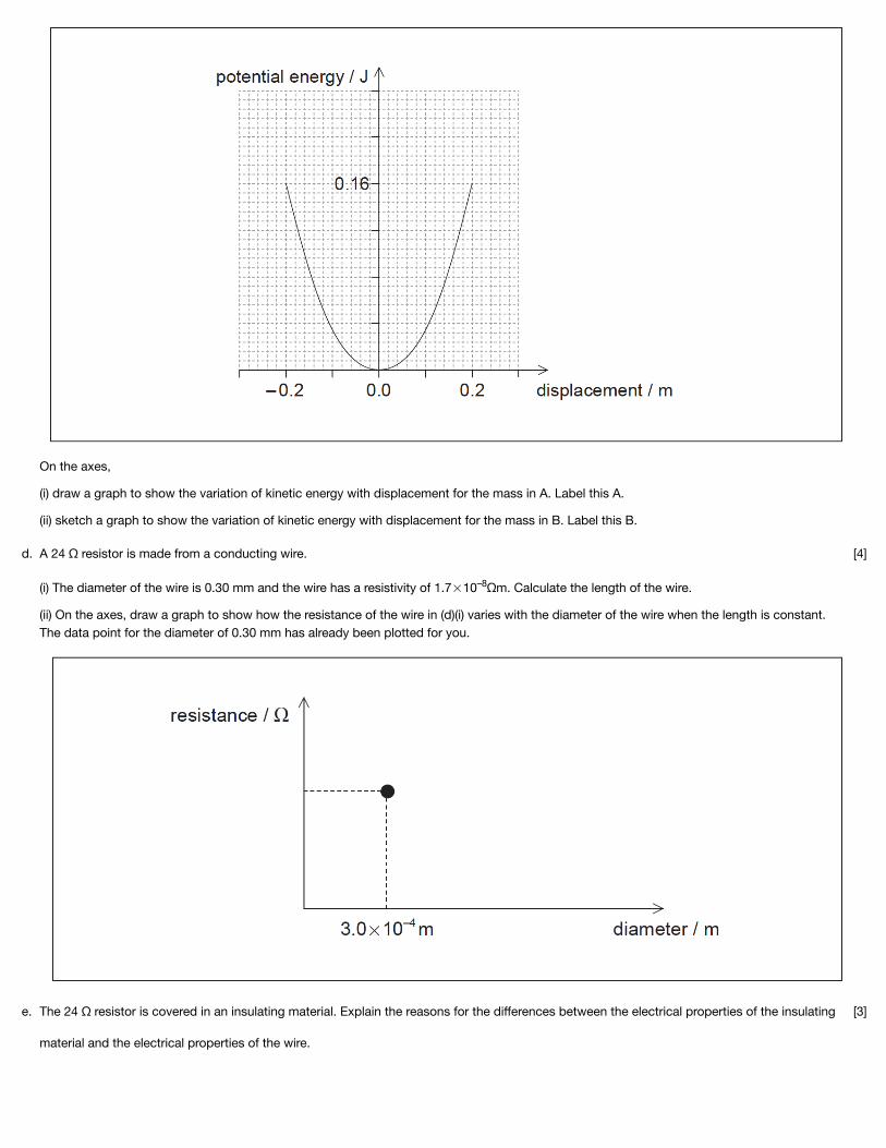
On the axes,
(i) draw a graph to show the variation of kinetic energy with displacement for the mass in A. Label this A.
(ii) sketch a graph to show the variation of kinetic energy with displacement for the mass in B. Label this B.
A 24 Ω resistor is made from a conducting wire.
(i) The diameter of the wire is 0.30 mm and the wire has a resistivity of 1.7 10 Ωm. Calculate the length of the wire.
(ii) On the axes, draw a graph to show how the resistance of the wire in (d)(i) varies with the diameter of the wire when the length is constant.The data point for the diameter of 0.30 mm has already been plotted for you.
–8
[4]d.
The 24 Ω resistor is covered in an insulating material. Explain the reasons for the differences between the electrical properties of the insulating
material and the electrical properties of the wire.
[3]e.

Markscheme
An electric circuit consists of a supply connected to a 24Ω resistor in parallel with a variable resistor of resistance R. The supply has an emf of
12V and an internal resistance of 11Ω.
Power supplies deliver maximum power to an external circuit when the resistance of the external circuit equals the internal resistance of thepower supply.
(i) Determine the value of R for this circuit at which maximum power is delivered to the external circuit.
(ii) Calculate the reading on the voltmeter for the value of R you determined in (f)(i).
(iii) Calculate the total power dissipated in the circuit when the maximum power is being delivered to the external circuit.
[8]f.
ma kx;
; (condone lack of negative sign)
or
implied use of defining equation for simple harmonic motion ;
so ;
a.
(i) 0.833 (Hz);
(ii) frequency/period is the same so ω is the same;k is the same (as springs are identical);(so m is the same)
b.

(ii) end displacements correct 0.01m;maximum lower than 0.16J;maximum equal to 0.04J half square;
c.
(i) seen / correct substitution
into equation: ; } (condone use of r for in first alternative)
99.7 (m); Award [2] for bald correct answer.Award [1 max] if area is incorrectly calculated, answer is 399 m if conversion to radius ignored, ie: allow ECF for second marking point if area isincorrect provided working clear.
(ii) any line showing resistance decreasing with increasing diameter and touchingpoint;correct curved shape showing asymptotic behavior on at least one axis;
d.
current/conduction is (related to) flow of charge;
conductors have many electrons free/unbound / electrons are the charge carriers / insulators have few free electrons;
pd/electric field accelerates/exerts force on electrons;
smaller current in insulators as fewer electrons available / larger current in conductors as more electrons available;
e.

Examiners report
(i) use of total resistance = 11Ω; (can be seen in second marking point)
;
20.3(Ω) ;
(ii) as current is same in resistor network and cell and resistance is same, half of emf must appear across resistor network;6.0 (V);
or
;
V=(0.545×11=) 6.0 (V);
Other calculations are acceptable.Award [2] for a bald correct answer.
(iii) use of 22 (ohm) or 11+11 (ohm) seen;use of or equivalent;6.54 (W);Award [3] for bald correct answer.Award [2 max] if cell internal resistance ignored, yields 3.27 V.
f.
[N/A]a.[N/A]b.[N/A]c.[N/A]d.[N/A]e.[N/A]f.
This question is in two parts. Part 1 is about a thermistor circuit. Part 2 is about vibrations and waves.
Part 1 Thermistor circuitThe circuit shows a negative temperature coefficient (NTC) thermistor X and a 100 kΩ fixed resistor R connected across a battery.
The battery has an electromotive force (emf) of 12.0 V and negligible internal resistance.

Part 2 Vibrations and waves
The cone and dust cap D of a loudspeaker L vibrates with a frequency of 1.25 kHz with simple harmonic motion (SHM).
(i) Define electromotive force (emf).
(ii) State how the emf of the battery can be measured.
[2]a.
The graph below shows the variation with temperature T of the resistance R of the thermistor.X [7]b.

(i) Determine the temperature of X when the potential difference across R is 4.5V.
(ii) State the range of temperatures for which the change in the resistance of the thermistor is most sensitive to changes in temperature.
(iii) State and explain the effect of a decrease in temperature on the ratio
.
Define simple harmonic motion (SHM). [2]c.
D has mass 6.5 10 kg and vibrates with amplitude 0.85 mm.
(i) Calculate the maximum acceleration of D.
(ii) Determine the total energy of D.
−3 [4]d.
The sound waves from the loudspeaker travel in air with speed 330 ms .
(i) Calculate the wavelength of the sound waves.
(ii) Describe the characteristics of sound waves in air.
−1 [2]e.
A second loudspeaker S emits the same frequency as L but vibrates out of phase with L. The graph below shows the variation with time t of the
displacement x of the waves emitted by S and L.
[6]f.

Markscheme
(i) Deduce the relationship between the phase of L and the phase of S.
(ii) On the graph, sketch the variation with t of x for the wave formed by the superposition of the two waves.
(i) the work done per unit charge in moving a quantity of charge completely around a circuit / the power delivered per unit current / work done per
unit charge made available by a source;
(ii) place voltmeter across battery;
a.
(i) VX = 7.5 V;
or ;
or ;
T= −37 or −38ºC
(ii) −50 to (up to) −30 °C / at low temperatures;
(iii) as the temperature decreases Rx increases;
same current through R and X so the ratio increases or VX increases and VR decreases so the ratio increases;
b.
(periodic) motion in which acceleration/restoring force is proportional to the displacement from a fixed point;
directed towards the fixed point / in the opposite direction to the displacement;
c.

Examiners report
(i) ω=(2πf = 2π×1250)7854 rad s–1;
a0 =(−ω2x0 = −78542 ×0.85×10–3 =) (−)5.2×10⁴ ms−2 ;
(ii) correct substitution into irrespective of powers of 10;
0.14 to 0.15 J;
d.
(i) 0.264 m;
(ii) longitudinal;
progressive / propagate (through the air) / travels with constant speed (through the air);
series of compressions and rarefactions / high and low (air) pressure;
e.
(i) S leads L / idea that the phase of L is the phase of S minus an angle;
period / 1×10⁻⁴ s / 0.1 ms;
/ 0.79 rad / 45 degrees;
(ii) agreement at all zero displacements;
maxima and minimum at correct times;
constant amplitude of 1.60 mm;
f.

[N/A]a.[N/A]b.[N/A]c.[N/A]d.[N/A]e.[N/A]f.