Embed Size (px)
Citation preview

1
Mercedes-Benz
SL Owners Manual300 SL500 SL

2
Product informationKindly observe the following in your own best interest:We recommend using Mercedes-Benz original parts as well as conversion parts and accessories explicitly approved by us foryour vehicle model. We have tested these parts to determine their reliability, safety and their special suitability for Mercedes-Benz vehicles.We are unable to make an assessment for other products and therefore cannot be held responsible for them, even if in individual casesan official approval or authorization by governmental or other agencies should exist. Use of such parts and accessories couldadversely affect the safety, performance or reliability of your vehicle. Please do not use them. Mercedes-Benz original parts as well asconversion parts and accessories approved by us are available at your authorized Mercedes-Benz Center where you will receivecomprehensive information, also on permissible technical modifications, and where proper installation will be performed.
Our company and staff congratulate you on the purchase of your new Mercedes-Benz.Your selection of our product is a demonstration of your trust in our company name. Further, it exemplifies your desire to own anautomobile that will be as easy as possible to operate and provide years of service.Your Mercedes-Benz represents the efforts of many skilled engineers and craftsmen. To ensure your pleasure of ownership, andfor your safety and that of your passengers, we ask you to make a small investment of your time:
• Please read this manual carefully before putting it aside. Then return it to your vehicle where it will be handy foryour reference.
• Please abide by the recommendations contained in this manual. They are designed to acquaint you with theoperation of your Mercedes-Benz.
• Please abide by the warnings and cautions contained in this manual. They are designed to help improve the safetyof the vehicle operator and occupants.
We extend our best wishes for many miles of safe, pleasurable driving.DaimlerChrysler AG

3
Owners ManualThis Owner Manual contains a great deal of useful information. We urge you to read it carefully and familiarize yourself with thevehicle before driving.For your own safety and longer service life of the vehicle, we urge you to follow the instructions and warnings contained in thismanual. Ignoring them could result in damage to the vehicle or personal injury to you or others. Vehicle damage caused by failure tofollow instructions is not covered by the Mercedes-Benz Limited Warranty.Your vehicle may have some or all of the equipment described in this manual. Therefore, you may find explanations for optionalequipment not installed in your vehicle. If you have any questions about the operation of any equipment, your authorized Mercedes-Benz Center will be glad to demonstrate the proper procedures.
Service and warranty information
The Service and Warranty Information Booklet contains detailed information about the warranties covering your Mercedes-Benz,including:• New Car Limited Warranty,
• Emission System Warranty,
• Emission Performance Warranty,
• California, Massachusetts, and Vermont Emission Control System Warranty(California, Massachusetts, and Vermont only),
• State Warranty Enforcement Laws (Lemon Laws).
4
Important notice for California retail buyers of Mercedes-Benz automobilesUnder California law you may be entitled to a replacement of your vehicle or a refund of the purchase price, if Mercedes-Benz USA,LLCor its authorized Mercedes-Benz Center fails to conform the vehicle to its express warranties after a reasonable number of repair attemptsduring the period of one year or 12 000 miles from original delivery of the vehicle. A reasonable number of repair attempts is presumed fora retail buyer (1) if the vehicle is out of service by reason of repair of substantial nonconformities for a cumulative total of more than 30calendar days or (2) the same substantial non-conformity has been subject to repair four or more times and you have at least oncedirectly notified us in writing of the need to repair the non-conformity and have given us an opportunity to perform the repairourselves. Notifications should be sent to the nearest Mercedes-Benz Regional Office listed in the Service and WarrantyInformation Booklet.
MaintenanceThe Service Booklet describes all the necessary maintenance work which should be performed at regular intervals.Always have the Service Booklet with you when you take the vehicle to your authorized Mercedes-Benz Center for service.The service advisor will record each service in the booklet for you.
Roadside assistanceThe Mercedes-Benz Roadside Assistance Program provides factory trained technical help in the event of a breakdown. Calls to thetoll-free Roadside Assistance number:1-800-FOR-MERCedes (in the USA)1-800-387-0100 (in Canada)will be answered by Mercedes-Benz Client Assistance Representatives 24 hours a day, 365 days a year.For additional information refer to the Mercedes-Benz Roadside Assistance Program brochure in your glove box.
5
Change of address or ownershipIf you change your address, be sure to send in the "Change of Address Notice" found in the Service and Warranty InformationBooklet, or simply call the Mercedes-Benz Client Assistance Center (in the USA) at 1-800-FOR-MERCedes, or Customer Service (inCanada) at 1-800-387-0100. It is in your own interest that we can contact you should the need arise.If you sell your Mercedes, please leave all literature with the vehicle to make it available to the next operator.If you bought this vehicle used, be sure to send in the "Notice of Purchase of Used Car" found in the Service and WarrantyInformation Booklet, or call the Mercedes-Benz Client Assistance Center (in the USA)at 1-800-FOR-MERCedes, or Customer Service (in Canada) at 1-800-387-0100.
Operating your vehicle outside the USA or CanadaIf you plan to operate your vehicle in foreign countries, please be aware that:
• Service facilities or replacement parts may not be readily available,
• unleaded gasoline for vehicles with catalytic converters may not be available; the use of leaded fuels will damage the catalysts,• gasoline may have a considerably lower octane rating, and improper fuel can cause engine damage.
Certain Mercedes-Benz models are available for delivery in Europe under our European Delivery Program.For details, consult your authorized Mercedes-Benz Center or write to:
In the USA: In Canada:Mercedes-Benz USA, Mercedes-Benz Canada, Inc.LLC European Delivery Department European Delivery DepartmentOne Mercedes Drive 849 Eglinton Avenue EastMontvale, NI 07645-0350 Toronto, Ontario M4G 2L5

6
We continuously strive to improve our product, and ask for your understanding that we reserve the right to make changes in design andequipment. Therefore, information, illustrations and descriptions in this Operator's Manual might differ from your vehicle.Optional equipment is also described in this manual, including operating instructions wherever necessary. Since they are special-orderitems, the descriptions and illustrations herein may vary slightly from the actual equipment of your vehicle.If there are any equipment details that are not shown or described in this Operator's Manual, your authorized Mercedes-Benz Center will be glad to inform you of correct care and operating procedures.The Operator's Manual and Service Booklet are important documents and should be kept with the vehicle.
7
Check Regularly and Before a Long Trip
See page 144
The First 1000 Miles (1500 km)
The more cautiously you treat your vehicle during the break-in period, the more satisfied you will be with its performance later on.Therefore, drive your vehicle during the first 1500 km (1000 miles) at moderate vehicle and engine-speeds.During this period, avoid heavy loads (full throttle driving) and high RPM (no more than 2/3 of maximum permissible speed in eachgear as indicated on the speedometer).
Downshift at proper engine speed!
On vehicles with automatic transmission avoid accelerating by kickdown. It is not recommended to brake the vehicle by manuallyshifting to a lower gear. We recommend to select positions "4" (for model 300 SL), "3" or "2" only at moderate speeds (for hilldriving).After 1500 km (1000 miles) speeds may be gradually increased to the permissible maximum.

8
Introduction Power Seats 33 Power Windows 60Product information 2 Orthopedic Seat Backrest 36 Roll Bar 60Operator's manual 4 Heated Seats 37 Hardtop 62At the Gas Station 145 Arm Rest 38 Soft top 66Check Regularly 144 Adjusting steering Column 38 Wind Screen 69Service LiteratureIndex
143140
Seat belts and Supplemental restraintsystem (SRS) 39
Automatic Antenna 71
Seat belts 39 Driving
Instruments and controls Emergency tensioning retractor (ETR) 42 Parking Brake 74Airbag 43 Starting and Shifting Gears 74
Instruments and controls 10 Steering Lock 48 Manual Transmission 75Instrument Cluster 12 Combination Switch 50 Automatic Transmission 76Indicator Lamp Symbols 13 Exterior Lamp Switch 52 Cruise Control 81Catalytic Converter 14 Exterior Rear View Mirrors 53 Charge Indicator Lamp 83Starting and Turning Offthe Engine
15 Inside Rear View Mirror 54 Oil Pressure Gauge with OilPressure Warning Lamp 83
Driving Instructions 16 Sun Visors 55 Low Engine Oil LevelWarning Lamp
84
MERCEDES-BENZMaintenance System
20 Setting Clock 55 Engine Oil Consumption 84
Interior Lighting 56 Fuel Consumption Gauge 84Operation
Automatic Climate Control22
Storage Compartment (EyeglassesCompartment) in the DashboardLighter
5757
Fuel Reserve Warning LampOutside Temperature Indicator
8585
Car keys 26 Console Storage Compartments 58 Coolant Temperature Gauge 85Infrared Remote Control 27 Door Pockets 58 Low Engine Coolant Level
Warning Lamp86
Central Locking system 29 Rear Storage Compartments 58 Roll Bar Warning Lamp 86Anti-Theft Alarm System 32 Rear Window Defroster 59

9
Low Windshield and Head LampWasher Fluid Level Warning Lamp 86
Vehicle Jack 99 Layout of Poly-V-Belt Drive 123
Seat Belt and Backrest LockWarning Lamp 87
Vehicle Tools 99 MERCEDES-BENZSpare Parts Service
123
Exterior Lamp Failure Indicator Lamp 87 Wheels 99Brake Pad Wear Indicator Lamp 88 Changing Wheels 101Brake Warning Lamp 88 Tire Pressure 104 Technical Data. Fuels,
Coolants, Lubricants etc.Consumer Information
ABS (Antilock Brake System)Warning Lamp 89
Battery 105
Emission Control 90 Spark Plugs 106 Identification Plates 126On-Board Diagnostic System(California models only) 90
Fuses 106 Theft Prevention 127
Traveling Abroad 91 Adjusting Headlamps 107 Vehicle Data Card 128Winter Driving 91 Replacing Bulbs 107 Warranty Coverage 128Snow Chains 91 Jump Starting 109 Technical Data
300SL 129Practical Hints Towing the Vehicle 111 500SL 131
Hood 94 Cleaning and Care of the Vehicle 112 Fuels, Coolants, Lubricants etc. 133Checking Coolant Level 95 Testing Infrared Remote Control 116 Capacities 133Adding Coolant 95 Locking Soft Top Manually 117 Engine Oils 136Checking Engine Oil Level 96 Locking Hardtop Manually 120 Brake Fluid 136Checking Automatic Trans. Fluid Level 97 Ashtray 121 Premium Unleaded Gasoline 136Trunk Lamp 98 Manual Release of Fuel Filler Flap 121 Fuel Requirements 136Spare Wheel 98 Ski Rack 121 Coolants 137First Aid Kit 98 Replacing Wiper Blades 122 Consumer Information 138

10
Instruments and Controls
For more detailed descriptions see specified pages
1 Adjustable air outlet (page 22) 16 Air volume control for center air outlet (page 22)2 Exterior lamp switch (page 52) 17 Air volume control for right air outlet (page 22)3 Parking brake release (page 74) 18 Automatic climate control (page 22)4 Hood lock release (page 94) 19 Radio5 Parking brake pedal (page 74) 20 Rear window defroster switch (page 59)6 Combination switch (page 50) 21 Hazard warning flasher switch7 Cruise control (page 81) 22 Automatic antenna switch (page 71)8 Horn, airbag (page 43) 23 Roll bar operation switch (page 60)9 Instrument cluster (page 12) 24 Compartment (to open press bottom of cover)10 Steering lock with ignition/starter switch (page 48) 25 Mirror adjustment switch (pages 53, 54)11 Adjustable air outlet (page 22) 26 Soft/hardtop operation switch (pages 62, 66)12 Heated air supply button - center air outlet (page 22) 27 Power window switch (page 60)13 Non-heated/cooled air supply button - center air outlet
(page 22)28 Seat heater switch (page 37)
14 Storage/eyeglasses compartment (page 57) 29 Ashtray with lighter (page 57)15 Air volume control for left air outlet (page 22)

11

12
Instrument Cluster
1 Fuel gauge with reserve warning lamp (yellow). p 85 9 Main odometer2 Coolant temperature gauge. See page 85. 10 Outside temperature indicator. See page 85.3 Fuel consumption gauge. See page 84. 11 Right turn signal indicator lamp (green)4 Oil pressure gauge (bar) with warning lamp (red). p 83. 12 Knob for setting clock (to adjust pull knob out
and rotate). See page 55.5 Left turn signal indicator lamp (green) 13 Tachometer6 Knob for instrument lamps and trip odometer.
Rotate knob: To vary intensity of instrument lamps.Depress knob: To reset trip odometer.
14 Red marking on tachometer: Excessive engine speed.
7 Speedometer 15 Electric clock8 Trip odometer

13
Indicator Lamp SymbolsFunction Indicator Lamp
High beam
Warning Lamp(should go out with the engine running unless)
Battery not being charged properly. See page 83. Front brake pads worn down. See page 88.
Fluid level for windshield and headlamp washersystem low. See page 86.
Brake fluid low (except Canada). Parking brakeengaged. See pages 74, 88.
Coolant level low. See page 86. Brake fluid low (Canada only). Parking brakeengaged. See pages 74, 88.
Engine oil level low. See page 84. SRS malfunction. See page 43.
Exterior lamp failure. See page 87. Fasten seat belts. Backrest not locked.See pages 39,87.
Roll bar malfunction. See page 86.
ABS malfunction. See page 89
Engine malfunction.If the lamp comes on when the engine is running, itindicates a malfunction of the 02-sensor on Federalversion vehicles, and fuel injection system oremission control system on the California versionvehicles. In either case, we recommend that youhave the malfunction checked as soon as possible.See page 90.
14
Catalytic Converter
Your MERCEDES-BENZ is equippedwith monolithic type catalytic converters,an important element in conjunction withthe O2 sensor to achieve substantialcontrol of the pollutants in the exhaustemissions. Keep your vehicle in properoperating condition by following our re-commended maintenance instructions asoutlined in your Maintenance Booklet.
Caution!
To prevent damage to the catalyticconverters, use only premium unleadedgasoline in this vehicle.
Any noticeable irregularities in engineoperation should be repaired promptly.Otherwise, excessive unburned fuelmay reach the catalytic convertercausing it to overheat.
Warning!
As with any vehicle, do not idle, parkor operate this vehicle in areas wherecombustible materials such as grass,hay or leaves can come into contactwith the hot exhaust system, as thesematerials could be ignited.

15
Starting and Turning off the Engine
Before Starting
• Engage parking brake.Move gearshift lever to neutral(selector lever position "P" onautomatic transmissions).
• Turn key in steering lock to position2. The charge indicator lamp shouldcome on.
Cold Engine
Turn key in steering lock clockwise tothe stop. Do not depress accelerator.Release key only when the engine isfiring regularly.
Hot EngineTurn key in steering lock clockwise tothe stop. Do not depress accelerator. Ifthe engine has not fired after approx. 4seconds, depress accelerator andcontinue cranking until the engine isfiring regularly. Release key and backoff accelerator.At very high coolant temperatures theengine starting time can be shortened ifthe accelerator is depressed slowly atthe beginning of the starting process.
Turning OffTurn the key in the steering lock toposition 0 only when the vehicle hasstopped moving.Note:Vehicles with automatic transmission:the key can only be removed with theselector lever in position "P".If the coolant temperature is very high(e.g. after hard driving on mountainroads), do not shut off the engineimmediately, but allow it to run for 1 -2 minutes at increased idle speed withselector lever in neutral or position "P".
Note:Due to the installed starter non-repeatfeature, the key must be turnedcompletely to the left before attemptingto start the engine again.
Observe the oil pressure gaugeimmediately after starting the engine.In a very cold engine the oil pressurewill rise slowly after the engine hasstarted. Do not speed up the enginebefore pressure is registered on thepressure gauge.
The charge indicator lamp should goout as soon as the engine has started.
In areas where temperaturesfrequently drop below -25°C (-13°F)we recommend that an engine blockheater be installed.Your authorized MERCEDES-BENZdealer will advise you on this subject.
16
Driving InstructionsPower AssistanceWhen the engine is not running, thebrake and steering systems are withoutpower assistance. Under thesecircumstances, a much greater effort isnecessary to stop or steer the vehicle.
BrakesCaution!When driving down long and steepgrades, relieve the load on the brakesby shifting into a lower gear (selectorlever position "4" [for model 300 SL],"3", "2" or "B" [for model 500 SL] inthe case of automatic transmission).This helps prevent overheating of thebrakes and reduces brake pad wear. Donot exceed engine speed limits (seepages 78 or 80).After hard braking, it is advisable todrive on for some time, rather thanimmediately parking, so the air streamwill cool down the brakes faster.
Warning!After driving in heavy rain for sometime without applying the brakes orthrough water deep enough to wetbrake components, the first brakingaction may be somewhat reducedand increased pedal pressure maybe necessary. Be sure to maintain asafe distance from vehicles in front.
The condition of the parking brakesystem is checked each time the car isin the shop for the requiredmaintenance.Between maintenance checks, it is agood practice to apply the parkingbrake once or twice while driving atapproximately 50 km/h (30 mph) on adry straight road. Apply parking brakelightly until a slight drag on the wheelsis felt. Keep applying the brake forabout 10 seconds while pulling the re-lease handle out before releasing theparking brake completely. This practicewill keep the parking brake atmaximum efficiency.
Warning!The stop lamps will not come onwhen applying the parking brakeonly. Perform the procedure in theprevious paragraph only when theroad is clear of other traffic.Resting your foot on the brake pedalwill cause excessive and prematurewear of the brake pads.It can also result in the brakesoverheating thereby significantlyreducing their effectiveness. It maynot be possible to stop the car insufficient time to avoid an accident.
All checks and maintenance work onthe brake system should be carried outby an authorized MERCEDES-BENZdealer.
17
If the parking brake is released and thebrake warning lamp in the instrumentcluster stays on, the brake fluid level inthe reservoir is too low.Brake pad wear or a leak in the systemmay be the reason for low brake fluidin the reservoir.Have the brake system inspected at anauthorized MERCEDES-BENZ dealerimmediately.Install only brake pads and brake fluidrecommended by MERCEDES-BENZ.
Warning!If other than recommended brakepads are installed, the brakingproperties of the vehicle can beaffected to an extent that the safety issubstantially impaired.
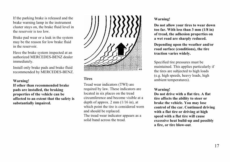
TiresTread wear indicators (TWI) arerequired by law. These indicators arelocated in six places on the treadcircumference and become visible at adepth of approx. 2 mm (1/16 in), atwhich point the tire is considered wornand should be replaced.The tread wear indicator appears as asolid band across the tread.
Warning!Do not allow your tires to wear downtoo far. With less than 3 mm (1/8 in)of tread, the adhesion properties ona wet road are sharply reduced.Depending upon the weather and/orroad surface (conditions), the tiretraction varies widely.
Specified tire pressures must bemaintained. This applies particularly ifthe tires are subjected to high loads(e.g. high speeds, heavy loads, highambient temperatures).
Warning!Do not drive with a flat tire. A flattire affects the ability to steer orbrake the vehicle. You may losecontrol of the car. Continued drivingwith a flat tire or driving at highspeed with a flat tire will causeexcessive heat build-up and possiblya fire, or tire blow-out.
18
AquaplaningDepending on the depth of the waterlayer on the road, aquaplaning mayoccur, even at low speeds and with newtires. Avoid track grooves in the roadarid apply brakes cautiously in the rain.
Tire TractionThe safe speed on a wet, snow coveredor icy road is always lower than on adry road.You should pay particular attention tothe condition of the road as soon as theprevailing temperatures fall close to thefreezing point.
Warning!If ice has formed on the road, tiretraction will be substantiallyreduced. Under such weatherconditions, drive, steer and brakewith extreme caution.
We recommend M + S radial-ply tiresfor the winter season for all four wheelsto insure normal balanced handlingcharacteristics.
On packed snow, they can reduce yourstopping distance as compared withsummer tires. Stopping distance,however, is still considerably greaterthan when the road is wet or dry.Parking
Warning!To reduce the risk of personal injuryas a result of vehicle movement,before turning off the engine andleaving the vehicle always:1. Keep foot on brake pedal.2. Firmly depress parking
brake pedal.3. Engage first or reverse
gear (selector leverposition "P" in the case ofautomatic transmissions).
4. Slowly release brake pedal.5. Turn front wheels towards
the road curb.6. Turn the key to steering
lock position 0 and remove.
Important!It is advisable to set the parking brakewhenever parking or leaving thevehicle. In addition, engage first orreverse gear (selector lever position"P"). When parking on hills, always setthe parking brake.
ClutchCaution!Resting your foot on the clutchpedal will cause excessive andpremature wear of the clutchcomponents.
19
Winter Driving InstructionsThe most important rule for slippery oricy roads is to drive sensibly and toavoid abrupt acceleration, braking andsteering action. Do not use the cruisecontrol system under such conditions.When the vehicle is in danger ofskidding, declutch, or in case ofautomatic transmission move selectorlever to position "N". Try to keep thevehicle under control by correctivesteering action.Road salts and chemicals can adverselyaffect braking efficiency. Increasedpedal force may become necessary toproduce the normal brake effect.
We therefore recommend depressingthe brake pedal repeatedly whentraveling on salt-strewn roads at length.This can bring road salt impairedbraking efficiency back to normal. Aprerequisite is, however, that this ispossible without endangering otherdrivers on the road.If the vehicle is parked after beingdriven on salt treated roads, the brakingefficiency should be tested as soon aspossible after driving is resumed whileobserving the safety rules in theprevious paragraph.
Warning!If the vehicle becomes stuck in snow,make sure that snow is kept clear ofthe exhaust pipe and from aroundthe vehicle with engine running.Otherwise, deadly carbon monoxide(CO) gases may enter vehicleinterior resulting in unconsciousnessand death.To assure sufficient fresh airventilation, open a window slightlyon the side of the car that is out ofthe wind.
20
MERCEDES-BENZMaintenance System
A maintenance booklet is included withyour car, listing all the maintenancejobs that must be carried out after thefollowing mileages:
Routine MaintenanceInspection at 1 300 – 1 600 km(800 - 1000 miles)Lubrication Service every 12 000 km(7 500 miles)Maintenance Service every 24 000 km(15 000 miles)Additional Work every 48 000 km(30 000 miles)For additional details refer to theMaintenance Booklet.In the case of low mileage operation,the Maintenance Service must becarried out at least once every 2 years.
Engine Oil and Filter Change
Required every 12 000 km (7500miles), or at least once a year.For engine oil recommendations, seepage 133.
Severe Operating ConditionsUnder severe operating conditions orheavy use, it may be necessary to carryout prescribed maintenance jobs atshorter intervals, for example:
Engine: Oil change with filter changeevery 6000 km (3750 miles)
Automatic transmission: Fluid changewithout filter change every 24 000 km(15 000 miles)
Tires: Inspect every 12 000 km (7500miles)
Air filter: Clean or replace elementevery 24 000 km (15 000 miles)
Note:Severe operating conditions or heavyuse include: predominant city or shortdistance driving, frequent mountaindriving, poor roads, dusty or muddyconditions, etc..
Special Maintenance MeasuresBrake fluid should be replaced every 2years, preferably in the spring.It is recommended to use only brakefluid approved by MERCEDES-BENZ.Do not mix different types of brakefluids.Have the engine coolant(water/anticorrosion/antifreezemixture) replaced every three years(see "Fuels, Coolants, Lubricants,etc.").
Maintenance VouchersYour authorized MERCEDES-BENZdealer will certify in the maintenancebooklet that all lubrication andmaintenance services have been carriedout at the correct intervals.

21
Operation
22
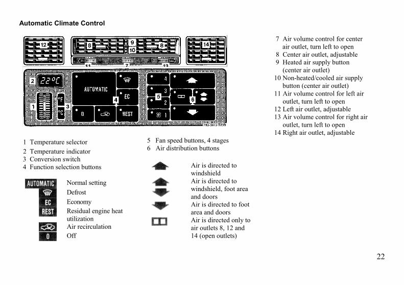
Automatic Climate Control
7 Air volume control for centerair outlet, turn left to open
8 Center air outlet, adjustable9 Heated air supply button
(center air outlet)10 Non-heated/cooled air supply
button (center air outlet)11 Air volume control for left air
outlet, turn left to open12 Left air outlet, adjustable13 Air volume control for right air
outlet, turn left to open14 Right air outlet, adjustable
1 Temperature selector2 Temperature indicator3 Conversion switch4 Function selection buttons
Normal settingDefrostEconomyResidual engine heatutilizationAir recirculationOff
5 Fan speed buttons, 4 stages6 Air distribution buttons
Air is directed towindshieldAir is directed towindshield, foot areaand doorsAir is directed to footarea and doorsAir is directed only toair outlets 8, 12 and14 (open outlets)
23
The temperature selected with thetemperature selector is reached asquickly as possible.The temperature selector should beleft at the desired temperature setting.The system will not heat or cool anyquicker by setting a higher or lowertemperature.The automatic climate control onlyoperates with the engine running.
Higher engine rpm results in highercoolant compressor rpm, therebyincreasing cooling capacity
If a higher heating or cooling capacityis required due to extreme outsidetemperatures, select a higher blowersetting.The automatic climate control removesconsiderable moisture from the airduring operation in the cooling mode.It is normal for water to drip on theground through ducts in the underbody.
Note:Outside air is drawn in through a filter.Dust particles (up to a certain size) andpollen are filtered out
1 Temperature SelectorSelect the desired temperature with thetemperature selector.A basic setting in the white field of theselector is recommended.The selected temperature is shown inthe indicator window 2. Withconversion switch 3, the selectedtemperature can be displayed in either°C or °F.
Note:If the temperature regulation becomesdefective, move the selector to eitherthe "10°C" ("50°F") or "40°C"("104°F") setting.10°C (50°F) = Heater turned off40°C (104°F) = Heater turned onIn these cases, we recommend that youhave the system checked at yourauthorized MERCEDES-BENZ dealer.
24
4 Function Selection Buttons
Normal SettingAir volume and distribution arecontrolled automatically.
To select:Press button(indicator lamp lights up)
To change selection:• Press , or button
(indicator lamp of selected buttonlights up). The indicator lamp for
button goes out.• Press either button 5 or 6 (indicator
lamp of selected button lights up).The indicator lamp forbutton goes out.
Defrost
Maximum heated and automaticallycontrolled amount of air is directed tothe windshield and side windows.As the engine coolant temperatureincreases, a higher blower stage isautomatically engaged, therebydefrosting as quickly as possible.Direct air outlets 12 and 14 towards theside windows. The outlets openautomatically.The center air outlets and the foot areaducts are closed.
To select:Press button (indicator lamplights up).
EconomyThe function of this setting correspondsto the normal setting. However, becausethe air conditioning compressor willnot engage (fuel savings), it is notpossible to air condition in this setting.
25
Residual Engine HeatUtilization
With the engine switched off, it ispossible to continue heating theinterior for a short while.Air volume and distribution arecontrolled automatically.
To select:Turn key in steering lock to position 1or 0 or remove key. Press button(indicator lamp lights up). Thisfunction selection will not activate ifthe engine coolant temperature isbelow 40°C (105°F) or if the batterycharge is insufficient.
To cancel:• Press button
(indicator lamp goes out).• Turn key in steering lock to
position 2.• Automatically shuts off after
approx. 30 minutes.
• Automatically shuts off if theengine coolant temperature dropsbelow 40°C (105°F).
• Automatically shuts off if thebattery voltage drops.
Air Recirculation
Outside air is not supplied to the car'sinterior.This mode can be selected to preventannoying odors or dust from enteringthe car's interior.
To select:Press button (indicator lamplights up).
To cancel: Press button(indicator lamp goes out).The system will automaticallyswitch from recirculated air to freshair if button is pressed:• after approx. 5 minutes at
outside temperatures belowapprox. 5°C (40°F),
• after approx. 30 minutes, atoutside temperatures aboveapprox. 5°C (40°F).
If button is pressed:• after approx. 5 minutes.Note:If the windows should fog up from theinside, switch from recirculated airback to fresh air.At high outside temperatures, thesystem automatically engages therecirculated air mode therebyincreasing the cooling capacityperformance.
OffThe fresh air supply to the car interioris shut off. While driving, use thissetting only temporarily, otherwise thewindows could fog up.
26
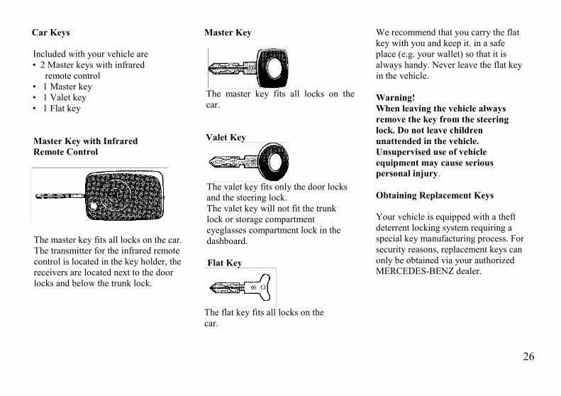
Car Keys
Included with your vehicle are• 2 Master keys with infrared
remote control• 1 Master key• 1 Valet key• 1 Flat key
Master Key with InfraredRemote Control
The master key fits all locks on the car.The transmitter for the infrared remotecontrol is located in the key holder, thereceivers are located next to the doorlocks and below the trunk lock.
Master Key
The master key fits all locks on thecar.
Valet Key
The valet key fits only the door locksand the steering lock.The valet key will not fit the trunklock or storage compartmenteyeglasses compartment lock in thedashboard.
Flat Key
The flat key fits all locks on thecar.
We recommend that you carry the flatkey with you and keep it. in a safeplace (e.g. your wallet) so that it isalways handy. Never leave the flat keyin the vehicle.
Warning!When leaving the vehicle alwaysremove the key from the steeringlock. Do not leave childrenunattended in the vehicle.Unsupervised use of vehicleequipment may cause seriouspersonal injury.
Obtaining Replacement Keys
Your vehicle is equipped with a theftdeterrent locking system requiring aspecial key manufacturing process. Forsecurity reasons, replacement keys canonly be obtained via your authorizedMERCEDES-BENZ dealer.
27
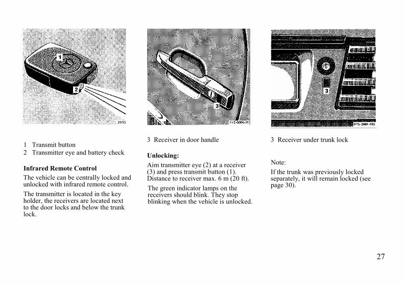
1 Transmit button2 Transmitter eye and battery check
Infrared Remote ControlThe vehicle can be centrally locked andunlocked with infrared remote control.The transmitter is located in the keyholder, the receivers are located nextto the door locks and below the trunklock.
3 Receiver in door handle
Unlocking:Aim transmitter eye (2) at a receiver(3) and press transmit button (1).Distance to receiver max. 6 m (20 ft).The green indicator lamps on thereceivers should blink. They stopblinking when the vehicle is unlocked.
3 Receiver under trunk lock
Note:If the trunk was previously lockedseparately, it will remain locked (seepage 30).

28
Locking:Aim transmitter eye (2) at a receiver(3) and press transmit button (1).Distance to receiver max. 6 m (20 ft).The red indicator lamps on thereceivers should blink. They stopblinking when the vehicle is locked.
Note:If a door or the trunk is not properlyclosed, the red indicator lamps willcontinue to blink (max. 10 seconds).
Open the door or trunk lid, close itproperly, and lock the car again.
4 Release button for master key
Master Key in Key HolderReleasing: press release button (4). Thekey unfolds from the holder by itself.Storing: press release button (4) andfold key back into holder.
Closing Windows from OutsideContinue to press transmit button (1)after locking car. The windows beginto close after approx. 1 second.
Warning!Never close the windows if there isdanger of anyone being harmed bythe raising window.In case of obstruction, the closingprocedure can be immediatelyinterrupted by releasing the transmitbutton. However, the windows canonly be lowered using the powerwindow buttons inside the car.
Note:If the vehicle cannot be locked orunlocked by pressing the transmitbutton (1), then it may be necessary tochange the batteries in the transmitter(If ok, battery indicator lamp intransmitter will light whentransmitting) or to synchronize thesystem, see "Practical Hints", page116.
29
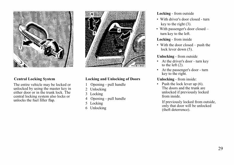
Central Locking SystemThe entire vehicle may be locked orunlocked by using the master key ineither door or in the trunk lock. Thecentral locking system also locks orunlocks the fuel filler flap.
Locking and Unlocking of Doors1 Opening - pull handle2 Unlocking3 Locking4 Opening - pull handle5 Locking6 Unlocking
Locking - from outside• With driver's door closed - turn
key to the right (3).• With passenger's door closed –
turn key to the left.Locking - from inside• With the door closed – push the
lock lever down (5).
Unlocking - from outside• At the driver's door - turn key
to the left (2).• At the passenger's door - turn
key to the right.Unlocking - from inside:• Push the lock lever up (6).
The doors and the trunk areunlocked if previously lockedfrom inside.If previously locked from outside,only that door will be unlocked(theft deterrence).

30
Note:The central locking system can only beengaged at the passenger door if thekey is removed from the steering lockor is inserted in the steering lockwithout having been turned.
If a door is not properly closed, unlockthe car, open and reclose the door, andlock the car again.
Locking and Unlocking atTrunk Lock1 Neutral position2 Unlocking3 Locking (detent)4 Separate locking of trunk
LockingTurn master key to position 3, turnback to position 1 and remove.
UnlockingTurn master key to position 2, turnback to position 1 and remove.
Separate Locking and Unlockingof TrunkIf the trunk is to remain locked (e.g.when leaving the car at a parkinggarage or workshop), lock the trunkseparately. Turn master key to position4 and remove in this position. Leaveonly the valet key with the vehicle.The trunk (and fuel filler flap) remainlocked - even if the central lockingsystem is engaged at a door fromoutside or inside the car (theftdeterrence).To unlock turn master key to position2, then back to position 1 and remove.

31
If the trunk is unlocked, the doors andfuel filler flap will also be unlocked.After closing the trunk, the centrallocking system must again be engagedto re lock the doors and fuel filler flap.If the fuel filler flap cannot be opened,refer to "Manual Release of Fuel FillerFlap" (page 121).
Closing Windows from OutsideTurn key in door lock or trunk lock tothe locking position and hold.The windows begin to close afterapprox. 1 second.
Warning!Never close the windows if there isdanger of anyone being harmed bythe raising window.In case of obstruction, the closingprocedure can be immediatelyinterrupted by turning the key backto the vertical position. However, thewindows can only be lowered usingthe power window buttons inside thecar.
Emergency Unlocking in Case ofAccidentThe doors unlock automatically a shorttime after the roll bar is deployed in anaccident (this is intended to aid rescueand exit). However, the key in thesteering lock must be in steering lockpositions 1, 2 or returned to position 0,but not removed.
32
Anti-Theft Alarm SystemThe anti-theft alarm can bearmed/disarmed with any of yourvehicle's keys or infrared remotecontrol by locking/unlocking eitherdoor or the trunk.
Operation:Once the alarm system has beenarmed, the exterior vehicle lamps willflash and the horn will soundintermittently when someone:• opens a door,• opens the trunk,• opens the hood,• removes the radio,• switches on or bridges the
ignition circuit,• steps on the brake pedal,• opens the storage compartment
between the front seats,
The alarm will last approximately 150seconds in the form of blinkingexterior lamps. At the same time analarm horn will sound intermittentlyfor 60 seconds, pause for 30 seconds,and repeat for another 60 seconds.The alarm will stay on even if theactivating element (a door, forexample) is immediately closed.Note:
If the radio is removed from itsmounting when the anti-theft alarm isarmed, the radio will automatically berendered inoperative! (This is indicatedby a dashed line across the display.)

33
Power SeatsThe switches are located in each frontdoor.Turn key in steering lock to position 1or 2 (with either door open, the powerseats can also be operated with the keyremoved or in steering lock position 0).
Warning!Do not adjust the driver's seatwhile driving. Adjusting the seatwhile driving could cause thedriver to lose control of the vehicle.
Adjusting
A Seat cushionB BackrestC Head restraint
(with shoulder belt heightadjustment)
Adjust the head restraint so that theupper portion of the shoulder belt islocated as close as possible to themiddle of the shoulder. The headrestraint can be tilted forward by hand.Note:When seat cushion is moved back inorder to prevent the backrest fromtouching the soft top storagecompartment cover when the seatcushion is moved back, the backrestwill automatically move to a moreupright position. When reclining thebackrest, the seat cushion willautomatically move forward to preventthe backrest from touching the soft topstorage compartment cover.
Warning!Never ride in a moving vehicle withthe seat back reclined. Sitting in anexcessively reclined position can bedangerous. You could slide under theseat belt in a collision, if you slideunder it, the belt would apply forceat the abdomen or neck. That couldcause serious or even fatal injuries.In a normal seated position the beltsprovide the best restraint for thewearer, as they are only thenproperly located on the body.
The rear storage area should neverbe occupied by passengers since thevehicle is a 2 seater.
Furthermore, there is a risk ofinjury in the rear by adjusting thepower assisted frontseats.
34
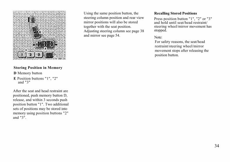
Storing Position in MemoryD Memory buttonE Position buttons "1", "2"
and "3"
After the seat and head restraint arepositioned, push memory button D,release, and within 3 seconds pushposition button "1". Two additionalsets of positions may be stored intomemory using position buttons "2"and "3".
Using the same position button, thesteering column position and rear viewmirror positions will also be storedtogether with the seat position.Adjusting steering column see page 38and mirror see page 54.
Recalling Stored PositionsPress position button "1", "2" or "3"and hold until seat/head restraint/steering wheel/mirror movement hasstopped.
Note:For safety reasons, the seat/headrestraint/steering wheel/mirrormovement stops after releasing theposition button.

35
BackrestFolding forward:Lift lever and fold forwards.
Folding back:Fold backrest back until it audiblylocks in place.
Warning!The seat belts provide protectiononly with the backrest locked inplace and, therefore, must be lockedin place with the vehicle in motion.Do not drive the car when the seat-back is not locked in place.
Note:If the backrest and seat belt warninglamp does not go out, but is instead litcontinuously, then a backrest is notengaged in its lock. Additionally, anaudible warning will sound for approx.20 seconds.Always provide sufficient room behindthe backrest and fold the backrest allthe way back until it can be heardlocking in place.The warning lamp goes out as soon asboth backrests are locked in place.
If both backrests are locked in placeand the warning lamp does not go out,have the system checked at yourauthorized MERCEDES-BENZ dealerimmediately.

36
1 Pressure regulator2 Height regulator
Orthopedic Seat Backrest
Some models may be equipped withorthopedic seats. These seats have aninflatable air cushion built into thebackrest to provide additional lumbarsupport.The pressure and height regulatorsare located on the driver's seat on theleft, on the passenger's seat on theright.
The amount of cushion height andcurvature may be adjusted afterturning the key to steering lockposition 1 or 2.
The inflation pressure of the aircushion can be varied betweenposition "0" = without pressure,and position "4" = maximumpressure, by changing the pressureregulator (1) setting. In addition, thecushion height may be changed tofive different settings betweenposition "a" = lowest setting, and"e" = highest setting, by varying theheight regulator (2) adjustment.
If the engine is turned off, the lastcushion setting is retained inmemory, and automatically adjuststhe cushion to this setting when theengine is restarted.

37
Heated SeatsThe seat heaters can be switched onwith the key in steering lock turned toposition 1 or 2.Turning on heater: Press upper half ofswitch = normal heating mode. Oneindicator lamp in the switch lights up.Press lower half of switch = rapidheating mode. Both indicator lamps "inthe switch light up.
After approximately 5 minutes in therapid heating mode, the heaterautomatically switches to normaloperation and only one indicator lampwill stay on.
Turning off heater:If one indicator lamp is on, pressupper half of switch.If both indicator lamps are on, presslower half of switch.If left on, the heater automatically turnsoff after approximately 30 minutes ofoperation.
Note:When in operation, the seat heaterconsumes a large amount of power. Itis advisable not to use the seat heaterlonger than necessary.
The seat heaters may automaticallyswitch off if too many powerconsumers are switched on at the sametime, or if the battery charge is low.When this occurs, the indicator lampin the switch will blink (both indicatorlamps blink during rapid seat heating).The seat heaters will switch on againautomatically as soon as sufficientvoltage is available.
If the blinking of the indicator lamps isdistracting to you, the seat heaters canbe switched off.

38
Arm Rest
To adjust: Press button (1) and slidearm rest forward or backward.
Adjusting Steering Column
Turn key in steering lock to position 1or 2 (with either door open, the steeringcolumn can be operated with the keyremoved or in steering lock position 0).To extend or retract: Move switch (1)in desired direction.To raise or lower: Move switch (1) indesired direction.
Storing Steering ColumnPosition in Memory
The steering column position is storedin memory together with the seat/headrestraint/mirror position and can berecalled when necessary, see page 34.
39
Seat Belts and SupplementalRestraint System (SRS)
Your vehicle is equipped with lap-shoulder seat belts, emergencytensioning retractors for the seat belts,driver airbag and knee bolster andpassenger airbag and knee bolster.
Seat Belts
Important!Laws in most states and all Canadianprovinces require seat belt use.All states and provinces require use ofchild restraints that comply with U.S.Federal Motor Vehicle Safety Standard213 and Canadian Motor VehicleSafety Standard 213.1. We stronglyrecommend their use.A statement by the child restraintmanufacturer of compliance with thisstandard can be found on theinstruction label on the restraint and inthe instruction manual provided withthe restraint.
Warning!If you are ever in an accident, yourinjuries can be considerably moresevere without your seat belt properlybuckled. Without your seat belt buck-led, you can hit the interior of thevehicle or be ejected from it. You canbe seriously injured or killed.In the same crash, the possibility forinjury or death is lessened with yourseat belt buckled.The seat belts provide protection onlywith the backrest locked in place. If theseat belt warning lamp does not go out,but is instead lit continuously, then abackrest is not engaged in its lock.
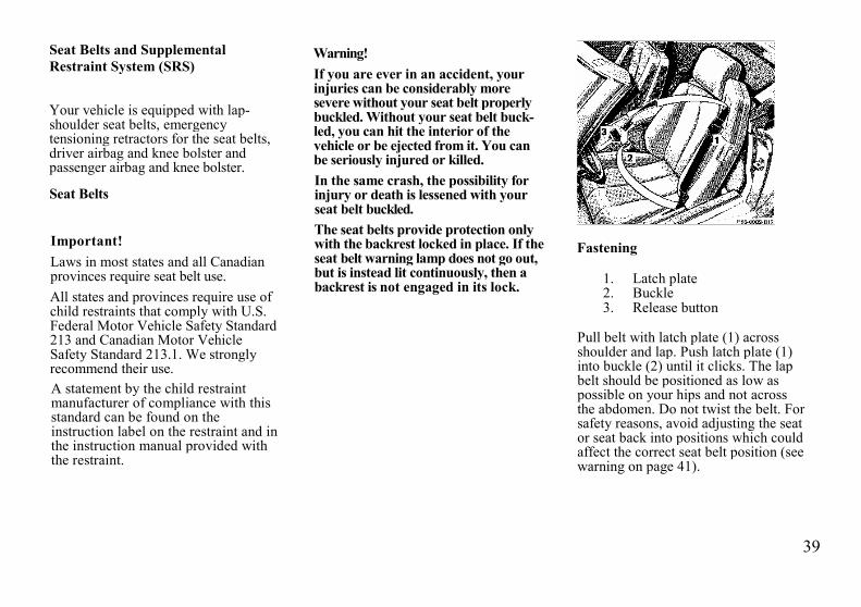
Fastening
1. Latch plate2. Buckle3. Release button
Pull belt with latch plate (1) acrossshoulder and lap. Push latch plate (1)into buckle (2) until it clicks. The lapbelt should be positioned as low aspossible on your hips and not acrossthe abdomen. Do not twist the belt. Forsafety reasons, avoid adjusting the seator seat back into positions which couldaffect the correct seat belt position (seewarning on page 41).

40
Press switch (4) to adjust seat belt sothat the top strap is running across themiddle of your shoulder.The belt must be pulled snug andchecked for snugness immediately afterengaging it and during driving. Ifnecessary, tighten the lap portion to asnug fit by pulling shoulder portion up.
UnfasteningPush in the red button (3) in the beltbuckle (2).Allow the retractor to completelyrewind the seat belt by guiding thelatch plate (1).
Operation:The inertia reel stops the belt fromunwinding during sudden vehicle stopsor when quickly pulling on the belt.The locking function of the reel may bechecked by quickly pulling out the belt.The emergency tensioning retractor(ETR) tightens the seat belt upon majorfrontal impacts within the shaded areashown on page 42.
41
Warning!• Each occupant should wear their
seat belt at all times. Together withthe "SRS", the seat belt offers thebest conditions for protection ofthe body in case of major frontalimpact
• Never wear the shoulder belt underyour arm, against your neck or offyour shoulder, in a crash, yourbody would move too far forward.That would increase the chance ofhead and neck injuries. The beltwould also apply too much force tothe ribs, this could severely injureinternal organs such as your liveror spleen. Position the lap belt aslow as possible on your hips and notacross the abdomen. If the belt ispositioned across your abdomen, itcould cause serious injuries in acrash.
• Improperly positioned belts do notprovide maximum protection andmay cause serious or fatal injuriesin case of an accident.
• Infants and small children must beseated in an infant or child restraintsystem, which is properly securedby the lap belt portion of the lap-shoulder belt Children could be en-dangered in an accident if theirchild restraints are not properlysecured in the vehicle.
• Children too big for child restraintsystems should use regular belts.Position shoulder belt across thechest and shoulder, not the face orneck, A booster seat may benecessary to achieve proper beltpositioning.
• Each seat belt should never be usedfor more than one person at a time.
• Belts should not be worn twisted.In a crash, you wouldn't have thefull width of the belt to takeimpact forces. The twisted beltagainst your body could causeinjuries.
• Pregnant women should also usethe lap-shoulder belt. The lap beltportion should be positioned aslow as possible on the hips to avoidany pressure on the abdomen.
For cleaning and care of the seat belts, seepage 113.
42
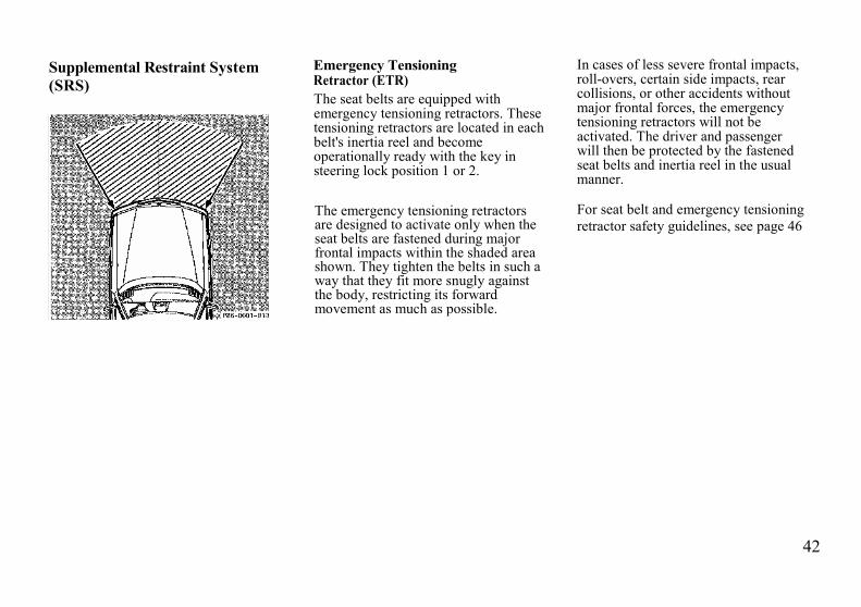
Supplemental Restraint System(SRS)
Emergency TensioningRetractor (ETR)The seat belts are equipped withemergency tensioning retractors. Thesetensioning retractors are located in eachbelt's inertia reel and becomeoperationally ready with the key insteering lock position 1 or 2.
The emergency tensioning retractorsare designed to activate only when theseat belts are fastened during majorfrontal impacts within the shaded areashown. They tighten the belts in such away that they fit more snugly againstthe body, restricting its forwardmovement as much as possible.
In cases of less severe frontal impacts,roll-overs, certain side impacts, rearcollisions, or other accidents withoutmajor frontal forces, the emergencytensioning retractors will not beactivated. The driver and passengerwill then be protected by the fastenedseat belts and inertia reel in the usualmanner.
For seat belt and emergency tensioningretractor safety guidelines, see page 46

43
AirbagsThe most effective occupant restraintsystem yet developed for use inproduction vehicles is the three pointseat belt. In some cases, however, theprotective effect of a seat belt can befurther enhanced by an airbag.
The driver airbag (1) is located in thesteering wheel hub. The passengerairbag (2) is located in the dashboardahead of the passenger. In conjunctionwith wearing the seat belts withemergency tensioning retractors (4),they provide increased protection forthe driver and passenger.
The operational readiness of the airbagsystem is verified by the indicatorlamp "SRS" (3) in the instrumentcluster. If no fault is detected, the lampwill go out after approximately 4seconds; after the lamp goes out, thesystem continues to monitor thecomponents and circuitry of the airbagsystem and will indicate a malfunctionby coming on again.

44
The following system components aremonitored or undergo a self-check:crash-sensor, airbag ignition circuits,driver and passenger seat belt buckles.Initially, when the key is turned fromsteering lock position 0 to positions 1 or2, malfunctions in the crash-sensor aredetected and indicated (the "SRS"indicator lamp stays on longer than 4seconds).In the operational mode, after theindicator lamp has gone out followingthe initial check, interruptions and shortcircuits in the airbag ignition circuit andin the driver and passenger seat beltbuckle harnesses, and low voltage in theentire system are detected andindicated.In the event a malfunction of the "SRS"is indicated as outlined above, the"SRS" may not be operational. Westrongly recommend that you visit anauthorized MERCEDES-BENZ dealerimmediately to have the systemchecked; otherwise the "SRS" may notbe activated in a major frontal accident.
Important!The airbags are designed to activateonly in certain frontal and front-angled impacts (within the shadedarea shown in the illustration onpage 44). Only during these types ofimpacts will they provide theirsupplemental protection. The driverand passenger should always wearthe seat belts, otherwise it is notpossible for the airbags to providetheir intended supplementalprotection.
In cases of other frontal impacts, roll-overs, certain side impacts, rearcollisions, or other accidents withoutfrontal forces, the airbag will not beactivated. The driver and passengerswill then be protected by the fastenedseat belts.
Important!The "SRS" is designed to reduce thepotential of injury in certain frontaland front-angled impacts which maycause injuries, however, no systemavailable today can totally eliminateinjuries and fatalities.The activation of the "SRS"temporarily releases a small amountof dust from the air-bags. This dust,however, is neither injurious to yourhealth, nor does it indicate a fire inthe vehicle.The service life of the airbagsextends to the date indicated on thelabel located on the driver-side doorlatch post To provide continuedreliability after that date, theyshould be inspected by an authorizedMERCEDES-BENZ dealer at thattime and replaced when necessary.
45
Warning!It is very important for your safety toalways be in a properly seatedposition.For maximum protection in the eventof a collision always be in normalseated position with your backagainst the seat back. Fasten yourseat belt and ensure that it isproperly positioned on the body.Since the airbag inflates withconsiderable speed and force, aproper seating position will keep youin a safe distance from the airbag:
• Sit properly belted in an uprightposition with your back against theseat back.
• Do not lean with your head or chestclose to the steering wheel ordashboard.
• Adjust the passenger as far aspossible rearward from thedashboard, especially when a childrestraint is installed.
• Fasten children weighing less than40 lbs. in child restraints.
• Infants and small children shouldonly be seated in an infant or childrestraint which is properly securedby the seat belt.
Failure to follow these instructionscan result in severe injuries to you orother occupants.

46
Safety Guidelines for the Seat Belt,Emergency TensioningRetractor and Airbag
Warning!• Damaged belts or belts that were
highly stressed in an accident mustbe replaced and their anchoringpoints must also be checked. Useonly belts installed or supplied byan authorized MERCEDES-BENZdealer.
• Do not pass belts over sharp edges.• Do not make any modification that
could change the effectiveness ofthe belts.
• The "SRS" is designed to functionon a one-time-only basis. An airbagor emergency tensioning retractor(ETR) that was activated must bereplaced.
• No modifications of anykind may be made to anycomponents or wiring of the"SRS". This includes theinstallation of additional trimmaterial, badges, etc. overthe steering wheel hub orfront passenger airbagcover and installation ofadditional electrical/electronicequipment on or neat "SRS"components and wiring.
• Improper work on the system,including incorrect installation andremoval, can lead to possibleinjury through an uncontrolledactivation of the "SRS".
• In addition, through improper workthere is the risk of rendering the"SRS" inoperative. Work on the"SRS" must therefore only beperformed by an authorizedMERCEDES-BENZ dealer.
• When scrapping the airbag unit oremergency tensioning retractor, it ismandatory to follow our safetyinstructions. These instructions areavailable at your authorizedMERCEDES-BENZ dealer.
When you sell the vehicle we stronglyurge you to give notice to the subsequentowner that it is equipped with an "SRS"by alerting him to the applicable sectionin the Owner's Manual.
47
Infants and Child Restraint SystemsWe recommend that all infants andchildren be restrained at all times whilethe vehicle is in motion.Important!The use of infant or child restraints isrequired by law in all 50 states and allCanadian provinces.Infants and small children should beseated in an infant or child restraintsystem, which is properly secured bythe lap belt portion of the lap-shoulderbelt, and that complies with U.S.Federal Motor Safety Standard 213 andCanadian Motor Vehicle SafetyStandard 213.1.A statement by the child restraintmanufacturer of compliance with thisstandard can be found on theinstruction label on the restraint and inthe instruction manual provided withthe restraint.
When using any infant or childrestraint system, be sure to carefullyread and follow all manufacturer'sinstructions for installation and use.
Warning!When the child restraint is not in use,remove it from the car or secure itwith the seat belt to prevent the loosechild restraint from becoming aprojectile in the event of an accident.Infants and small children shouldnever be held on the lap while thevehicle is in motion. During anaccident they would be almost impos-sible to hold, and could be crushedbetween the adult and the dashboard.Infants and small children shouldnever share a seat belt with anotheroccupant During an accident, theycould be crushed between the occu-pant and seat belt.
Children too big for child restraintsystems should use regular seat belts.Position shoulder belt across the chestand shoulder, not the face or neck. Abooster seat may be necessary toachieve proper belt positioning.
This vehicle is equipped with a tetheranchorage for use with child restraintsthat have a top tether strap. Consultyour authorized MERCEDES-BENZdealer for the exact location of thisanchorage.

48
Steering Lock0 Steering is locked when the key
is withdrawn and the steering lockis engaged.
The key can be withdrawn only inposition 0.
In models equipped with automatictransmission, the key can beremoved only with the selector leverin position "P".
With the key removed, the selectorlever is locked in position "P".
Warning!Models with manual transmission: Donot remove key from the steering lockwhile the vehicle is in motion as thiswill cause the engagement of thesteering lock, thus rendering thevehicle impossible to steer.
1 Steering is unlocked. (If necessary,move steering wheel slightly and turnkey clockwise to position 1.)
2 Driving position.3 Starting position.Note:For starting and turning off the engine,refer to page 15.
Warning!When leaving the vehicle alwaysremove the key from the steering lock.Do not leave children unattended inthe vehicle. Unsupervised use of vehicleequipment may cause serious personalinjury.

49
The following items can be operatedwith the key in steering lock position 1:
Wiper, windshield washer system,headlamp cleaning system(only in exterior lamp switch positions
or ),headlamp flasher,radio (also in position 0),lighter,rear window defroster,power windows,power seats,orthopedic seat backrest,heated seats,steering column adjustment.
An audible warning sounds when thedriver's door is opened with the key insteering lock positions 1 or 0.With the engine at idle speed, thecharging rate of the alternator (output)is limited.It is therefore recommended to turn offunnecessary electrical consumers whiledriving in stop-and-go traffic.This precaution helps to avoid drainingof the battery.
Unnecessary drain on the battery andcharging system may be minimized byturning off the following powerconsumers, for example: heated seats,rear window defroster. In addition, theautomatic climate control blower speedshould be set to stage "1".

50
Combination Switch
1 Low beam (exterior lampswitch position )
2 High beam (exterior lampswitch position )
3 High beam flasher (high beamavailable independent ofexterior lamp switch position)
4 Turn signals, right5 Turn signals, left
To signal minor directional changes,such as changing lanes on a highway,move combination switch to the pointof resistance only and hold it there.To operate the turn signalscontinuously, move the combinationswitch past the point of resistance (upor down). The switch is automaticallycanceled when the steering wheel isturned to a large enough degree.
6 Press switch briefly:One wipe without washer water
(select only if window is wet)
Press switch past resistance point:Windshield washer, windshieldwiper; headlamp cleaning system(only in exterior lamp switchpositions or Canada only:also in position when the engineis running)
7 Windshield wiper0 Wiper offI Intermittent wipingII Normal wiper speedIII Fast wiper speedWhen coming to a stop or drivingslower than approx. 20 km/h (13mph), the wiper speed automaticallyswitches to the next lower setting.In setting "I", the interval betweenwipes is lengthened.Upon accelerating again, the wiperspeed returns to the previous setting.
Note:The windshield washer reservoir,hoses and nozzles are automaticallyheated.

51
Windshield Washer Fluid MixingRatioFor temperatures above freezing:MB Windshield Washer Concentrate"S" and water 1 part "S" to 100 partswater (40 ml "S" to 1 gallon water).For temperature below freezing:MB Windshield Washer Concentrate"S" and commercially availablepremixed windshield washersolvent/antifreeze 1 part "S" to 100parts solvent (40 ml "S" to 1 gallonsolvent),Windshield Wiper SmearsIf the windshield wiper smears thewindshield, even during rain, activatethe washer system as often asnecessary. The fluid in the washerreservoir should be mixed in the correctratio.
Blocked Windshield WiperIf the windshield wiper becomesblocked (for example, due to snow),switch off the wiper motor.For safety reasons before removing iceor snow, remove key from steeringlock. Remove blockage.Activate combination switch again(key in steering lock position 1).
Emergency Operation ofWindshield WiperIn case of windshield wipermalfunction, turn combination switchto wiper setting II.Have the system checked at yourauthorized MERCEDES-BENZ dealeras soon as possible.
Signaling Turns with HazardFlasher in Use
For example, when the vehicle isbeing towed:With hazard flasher on, activatecombination switch for left or rightturn signal - only the selected turnsignal will blink.Upon canceling the turn signal, all fourturn signals will operate again.
Turn Signal FailureIf one of the turn signals fails, the turnsignal indicator system flashes andsounds at a faster than normal rate. Inaddition, the exterior lamp failureindicator will come on.

52
Exterior Lamp SwitchCanada only:When the engine is running, the lowbeam (includes parking lamps, sidemarker lamps, taillamps, license platelamps and instrument panel lamps) areautomatically switched on.
Off
Parking lamps (includesside marker lamps, tail-lamps, license plate lamps,instrument panel lamps)Canada only: When theengine is running, the lowbeam is additionallyswitched on.Parking lamps plus lowbeam or high beamheadlamps (combinationswitch pushed forward)Standing lamps, right (turnleft one stop).Standing lamps, left (turn
left two stops)Fog lamps (pull out onestop) with parking and/orheadlamps onRear fog lamp (pull out to2nd detent) In addition tofog lamps. Indicator lamp inlamp switch comes on
Standing LampsWhen the vehicle is parked on thestreet the standing lamps (right or leftside parking lamps) can be turned on,making the vehicle more visible topassing vehicles.The standing lamps can only beoperated with the key in steeringlock position 0 or 1.Note:With the key removed and a dooropen, an audible warning will sound ifthe vehicle's exterior lamps (exceptstanding lamps) are not switched off.Fog lamps will operate with theparking lamps and the low or highbeam headlamps. Fog lamps shouldonly be used in conjunction with lowbeam headlamps. Consult your stateMotor Vehicle Regulations regardingallowable lamp operation.Fog lamps are automatically switchedoff when the exterior lamp switch isturned to position
53
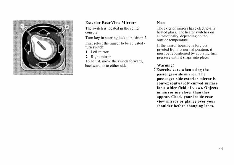
Exterior RearView MirrorsThe switch is located in the centerconsole.Turn key in steering lock to position 2.First select the mirror to be adjusted -turn switch:1 Left mirror2 Right mirrorTo adjust, move the switch forward,backward or to either side.
Note:The exterior mirrors have electric-allyheated glass. The heater switches onautomatically, depending on theoutside temperature.If the mirror housing is forciblypivoted from its normal position, itmust be repositioned by applying firmpressure until it snaps into place.
Warning!E Exercise care when using the
passenger-side mirror. Thepassenger-side exterior mirror isconvex (outwardly curved surfacefor a wider field of view). Objectsin mirror are closer than theyappear. Check your inside rearview mirror or glance over yourshoulder before changing lanes.

54
Inside Rear View Mirror,Electrically Adjustable
The switch is located in the centerconsole.Turn key in steering lock to position 2.Turn the switch for the exterior rearview mirror adjustment to its centerposition and adjust by moving theswitch forward, backward or to eitherside.Antiglare night position: Tilt the mirrorto the antiglare night position using thelever at its lower edge.
Storing Mirror Positions inMemory
The exterior and interior rear viewmirror positions are stored in memorywith the seat/head restraint/steeringcolumn position and can be recalledwhen necessary, see page 34.
Note:If the inside rear view mirror wasadjusted manually, the originallystored position remains in memory.To recall position, press the desiredposition button.

55
Sun VisorsSwing sun visors down to protectagainst sun glare.
If sunlight enters through a sidewindow, disengage visor from innermounting and pivot to the side. Fromthis position, the visor can slideforward and backward on its shaft.
Vanity mirror:With the visor engaged in its innermounting, the lamp can be switched onby opening the cover.
Setting ClockLocation of knob, see page 12.Adjusting clock ahead:Pull out adjustment knob, turn tothe right and hold.
Adjusting clock back:Pull out adjustment knob, turn tothe left and hold.
Adjusting clock one minute aheador back:Pull out adjustment knob, brieflyturn to the left or right and releaseknob.
Adjusting clock more than one minuteahead or back:
Pull out adjustment knob, turn to theleft or right and hold until the desiredtime is set.Adjusting speed: Within the first 2seconds, the minute hand advances 8minutes and advances another 8minutes every additional secondthereafter.

56
Entrance Lamps, Exit LampsEntrance lamps are located in thefootwells under the dashboard.Exit lamps are located in the doorpockets.These lamps are switched on and off bythe door contact switches.
Interior LightingThe switch is located above the insiderear view mirror.
Interior Lamps1 Interior lamps are switched on
and off delayed (no delay with keyin steering lock turned to position 2)by the door contact switches
2 Interior lamps switched off.3 Interior lamps switched on
Interior lamps switched on
Reading Lamps4 Left reading lamp switched on,5 Reading lamps switched off.6 Right reading lamp switched on.
57
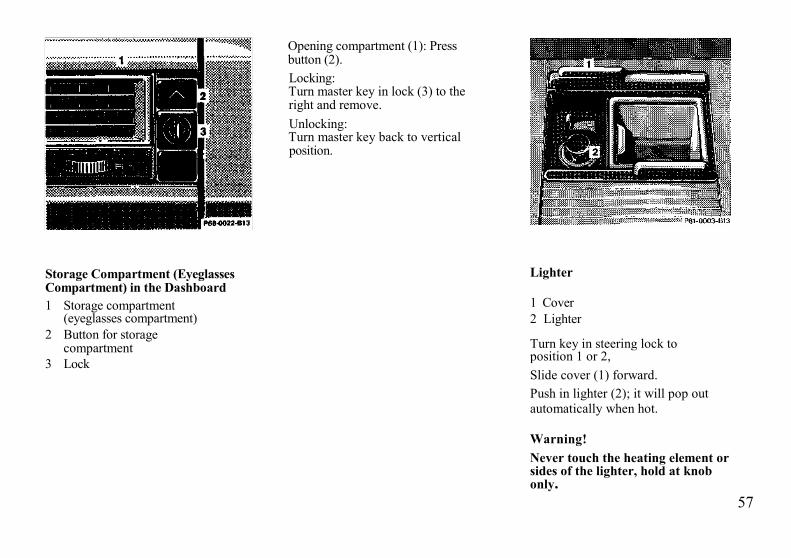
Opening compartment (1): Pressbutton (2).Locking:Turn master key in lock (3) to theright and remove.Unlocking:Turn master key back to verticalposition.
Storage Compartment (EyeglassesCompartment) in the Dashboard1 Storage compartment
(eyeglasses compartment)2 Button for storage
compartment3 Lock
Lighter
1 Cover2 Lighter
Turn key in steering lock toposition 1 or 2,Slide cover (1) forward.Push in lighter (2); it will pop outautomatically when hot.
Warning!Never touch the heating element orsides of the lighter, hold at knobonly.

58
Console Storage CompartmentsTo open front compartment (cassettestorage): Slide cover (1) back.Opening rear compartment: Pressbutton (2) and lift arm rest.
Door PocketsTo open: Lift cover,
Rear Storage CompartmentsTo open compartment: Press button (1)and lift cover.

59
Rear Window DefrosterThe switch is located in the centerconsole.Turn key in steering lock toposition 1 or 2.
When activating the rear windowdefroster, the indicator lamp in theswitch will come on.
Note:The rear window defroster uses a largeamount of power. To keep the batterydrain to a minimum, turn off thedefroster as soon as the window isclear. The defroster is automaticallyturned off after a maximum of 20minutes of operation. Heavyaccumulation of snow and ice shouldbe removed before activating thedefroster.
If several power consumers are turnedon simultaneously, or the battery isonly partially charged, it is possiblethat the defroster will automaticallyturn itself off. When this happens, theindicator lamp inside the switch startsblinking. As soon as the battery hassufficient voltage, the defrosterautomatically turns itself back on.
60
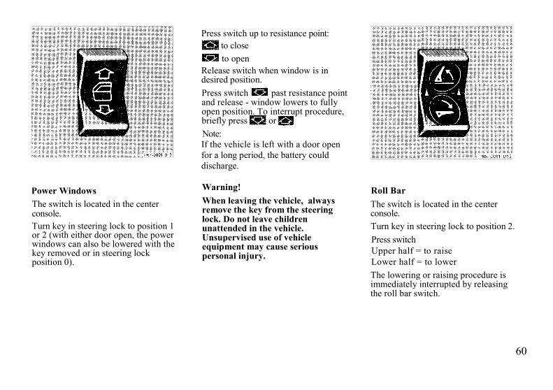
Press switch up to resistance point:to closeto open
Release switch when window is indesired position.Press switch past resistance pointand release - window lowers to fullyopen position. To interrupt procedure,briefly press orNote:If the vehicle is left with a door openfor a long period, the battery coulddischarge.
Power WindowsThe switch is located in the centerconsole.Turn key in steering lock to position 1or 2 (with either door open, the powerwindows can also be lowered with thekey removed or in steering lockposition 0).
Warning!When leaving the vehicle, alwaysremove the key from the steeringlock. Do not leave childrenunattended in the vehicle.Unsupervised use of vehicleequipment may cause seriouspersonal injury.
Roll BarThe switch is located in the centerconsole.Turn key in steering lock to position 2.Press switchUpper half = to raiseLower half = to lowerThe lowering or raising procedure isimmediately interrupted by releasingthe roll bar switch.

61
If the roll bar was raised using theswitch, it will be automatically loweredwhen activating the soft top switch.
The roll bar will be automaticallyraised in an accident or in a potentiallydangerous driving situation. A ratchetnoise can be heard when the roll bar isautomatically raised.
The roll bar can be lowered again afteran automatic deployment by pressingthe upper half of the roll bar switch (forat least 5 seconds) until the roll bardrive mechanism audibly engages.Then press the lower half of the switchto lower the roll bar.
Warning!This vehicle is a two occupantvehicle. The rear storage area shouldnever be used by any persons.Raising or lowering of the roll barcould injure rear seated occupants.
Before operating the roll bar switchmake sure that the roll bar's path isclear and no persons due toinattention are injured by themoving roll bar.For your own safety we recommendto drive with the roll bar raised, if
• the outside temperature is below -15°C (5°F)
• the soft top is closed and pets areplaced in the rear storage area.
Items being transported in the areabehind the seats should be placed insuch a manner as not to affect themovement of the roll bar when beingraised.
Note:
If the indicator lamps in the switch areblinking or if the warning lamp in theinstrument cluster comes on, then amalfunction has been detected.
In this case, drive only with the roll barraised until the defect has beenrepaired. Raise the roll bar by pressingthe upper half of the roll bar switch.The indicator lamps in the switch willgo out, however, the warning lamp inthe instrument cluster will stay on.
Have the system checked at yourauthorized MERCEDES-BENZ dealeras soon as possible.
Important!The roll bar is intended to be a safetyenhancement to the other featuresdesigned into the vehicle. No system inany vehicle can eliminate thepossibility of serious injury or fatalityin an accident. Properly fastened seatbelts and child restraints must be used!

62
HardtopThe removal or attachmentof the hardtop can be carried outby 2 persons.
Warning!Do not place your hands between thehardtop and the car body while thehardtop is being locked or unlocked.Serious personal injury may occur.
Removing HardtopEngage parking brake.Open doors or windows.Disconnect plug for rear windowdefroster. Fold cover (1) away andremove plug.
Turn key in steering lock to position 2(engine not running).Slide soft top switch (2) back within 10seconds of turning key and hold.The unlocking procedure begins afterapprox. 2 seconds:• The roll bar lowers.• The indicator lamp in the soft
top switch lights up.• The hardtop unlocks.

63
5. After the hardtop has unlockedremove the key from the steeringlock and turn radio off to lowerantenna. The indicator lamp in thesoft top switch should go out.
Important!Removal of the key from the steeringlock is a safety measure ensuring thatthe key cannot be turned to position 2and the soft top switch is withoutfunction should anybody push theswitch forward causing the rooflocking mechanism to work. If handsare at that moment between roof andcar body they can be badly injured.
6. Lift the hardtop vertically from itsattachment points (3) and locatingpoints (4) and carefully remove tothe rear. Exercise caution whenmaneuvering the top. To avoidpaint damage, the top's mountingpins must not be allowed to contactthe body.

64
Attaching Hardtop1. Engage parking brake and turn
key in steering lock to position 2,2. Lower roll bar,3. Open doors or windows.4 Turn radio off to lower power
antenna, turn key in steeringlock to position 0 and remove.
5 From the rear of the vehicle, lift thehardtop carefully over theattachment points (1) and locatingpoints (2). First guide the rear pins ofthe top vertically into the rearattachment points, then lower theroof onto the vehicle and locate thefront locking pins. Exercise cautionwhen maneuvering the top. To avoidpaint damage, the top's mountingpins must not be allowed to contactthe body.
6 Turn key in steering lock toposition 2. The indicator lampin the soft top switch lights up.
7 Slide soft top switch (3)forward - the hardtop should lockand the indicator lamp in theswitch should go out.
65
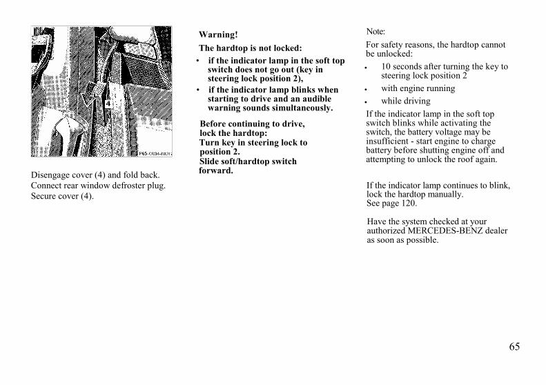
Disengage cover (4) and fold back.Connect rear window defroster plug.Secure cover (4).
Warning!The hardtop is not locked:
• if the indicator lamp in the soft topswitch does not go out (key insteering lock position 2),
• if the indicator lamp blinks whenstarting to drive and an audiblewarning sounds simultaneously.
Before continuing to drive,lock the hardtop:Turn key in steering lock toposition 2.Slide soft/hardtop switchforward.
Note:For safety reasons, the hardtop cannotbe unlocked:• 10 seconds after turning the key to
steering lock position 2• with engine running• while drivingIf the indicator lamp in the soft topswitch blinks while activating theswitch, the battery voltage may beinsufficient - start engine to chargebattery before shutting engine off andattempting to unlock the roof again.
If the indicator lamp continues to blink,lock the hardtop manually.See page 120.
Have the system checked at yourauthorized MERCEDES-BENZ dealeras soon as possible.
66
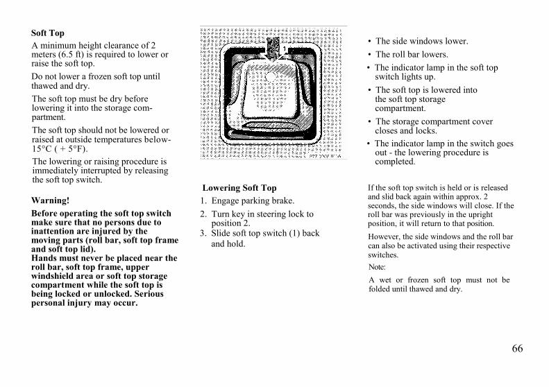
Soft TopA minimum height clearance of 2meters (6.5 ft) is required to lower orraise the soft top.Do not lower a frozen soft top untilthawed and dry.The soft top must be dry beforelowering it into the storage com-partment.The soft top should not be lowered orraised at outside temperatures below-15°C ( + 5°F).The lowering or raising procedure isimmediately interrupted by releasingthe soft top switch.
Warning!Before operating the soft top switchmake sure that no persons due toinattention are injured by themoving parts (roll bar, soft top frameand soft top lid).Hands must never be placed near theroll bar, soft top frame, upperwindshield area or soft top storagecompartment while the soft top isbeing locked or unlocked. Seriouspersonal injury may occur.
Lowering Soft Top1. Engage parking brake.2. Turn key in steering lock to
position 2.3. Slide soft top switch (1) back
and hold.
• The side windows lower.• The roll bar lowers.• The indicator lamp in the soft top
switch lights up.• The soft top is lowered into
the soft top storagecompartment.
• The storage compartment covercloses and locks.
• The indicator lamp in the switch goesout - the lowering procedure iscompleted.
If the soft top switch is held or is releasedand slid back again within approx. 2seconds, the side windows will close. If theroll bar was previously in the uprightposition, it will return to that position.However, the side windows and the roll barcan also be activated using their respectiveswitches.Note:A wet or frozen soft top must not befolded until thawed and dry.

67
Raising Soft Top1. Engage parking brake.Turn key in steering lock toposition 2.
3. Slide soft top switch (2) forward andhold:
• The side windows lower.• The roll bar lowers.• The indicator lamp in the soft top
switch lights up.• The soft top closes and locks.• The indicator lamp in the soft top
switch goes out -the closingprocedure is completed.
If the soft top switch is held or isreleased and slid forward again withinapprox. 2 seconds, the side windowswill close. If the roll bar waspreviously in the upright position, itwill return to that position.However, the side windows and theroll bar can also be activated usingtheir respective switches.
Note:If the soft top does not engage in thewindshield header attachment points,then release the soft top switch. Reachinto the grip (3) and guide the pinsinto their respective locks whilepulling down, slide soft top switch (2)forward again.

68
Warning!The soft top is not locked;• if the indicator lamp in the soft
top switch does not go out (key insteering lock position 2),
• if the indicator lamp blinks whenstarting to drive and an audiblewarning sounds simultaneously.
Stop the vehicle and beforecontinuing to drive, lock the softtop:The key should be in steering lockposition 2.Slide soft top switch forward, if thesoft top is not locked, it may foldback or forward when driving.During soft top operation, do notplace your hands near the soft topframe, upper windshield area or softtop storage compartment. Seriouspersonal injury may occur.
For safety reasons, the soft top cannotbe unlocked while driving,However, if the soft top is notcompletely locked, it can be lockedwhile driving by pushing thesoft/hardtop switch forward.If the indicator lamp in the soft topswitch blinks while activating theswitch,• the battery voltage may be
insufficient - start engine and letrun while activating switch,
• the system may be overloaded (forexample after lowering or raisingthe soft top approx. 5 consecutivetimes) - after approx. 2 minutes thesoft top switch may be activatedagain.
If the indicator lamp continues to blink,lock the soft top manually.See page 117.Have the system checked at yourauthorized MERCEDES-BENZ dealeras soon as possible.
Note:If the roll bar was raised automatically,the process of raising or lowering thesoft top will take somewhat longer, asthe roll bar must first be lowered.Whenever possible, park vehicle in theshade as continuous exposure to sunrays can prematurely deteriorate thesoft top material.The soft top may become moldy if it iskept in the storage compartment for anextended period.Therefore, we recommend raising andairing it thoroughly with the sidewindows open (do not expose it to thesun) at regular intervals during the wetand cold seasons.

69
Wind ScreenInstallation:1. Raise roll bar partially using
switch on center console.
2. Insert screen into roll bar bypositioning hook at bottom ofroll bar, on one side, then pushthe opposite side in place.
3. Slide wind screen up into roll bar(1), using care not to get theattachment straps (2) caught.
4 Raise roll bar completely.
5 Wrap attachment straps aroundroll bar and insert tabs intolatches (3).
6. Tighten straps (4).
7. Lower roll bar.

70
Removal1. Fold down top of wind screen.2. Raise roll bar using switch on
center console.3. Disconnect attachment strap
latches by squeezing latch.4. Lower roll bar partially.
Setting up
Push top of wind screen fully forwardagainst internal stop
Warning!The rear storage area should neverbe occupied by passengers since thevehicle is a 2 seater. Furthermore,with the wind screen in place there isa risk of injury, should the roll bar bedeployed.
5. Pull wind screen down out of rollbar (5) and lift wind screen out onone side and remove.
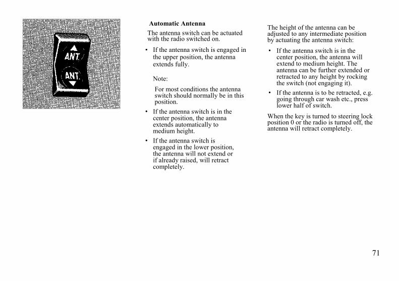
71
Automatic AntennaThe antenna switch can be actuatedwith the radio switched on.
• If the antenna switch is engaged inthe upper position, the antennaextends fully.
Note:For most conditions the antennaswitch should normally be in thisposition.
• If the antenna switch is in thecenter position, the antennaextends automatically tomedium height.
• If the antenna switch isengaged in the lower position,the antenna will not extend orif already raised, will retractcompletely.
The height of the antenna can beadjusted to any intermediate positionby actuating the antenna switch:• If the antenna switch is in the
center position, the antenna willextend to medium height. Theantenna can be further extended orretracted to any height by rockingthe switch (not engaging it).
• If the antenna is to be retracted, e.g.going through car wash etc., presslower half of switch.
When the key is turned to steering lockposition 0 or the radio is turned off, theantenna will retract completely.

72

73
Driving
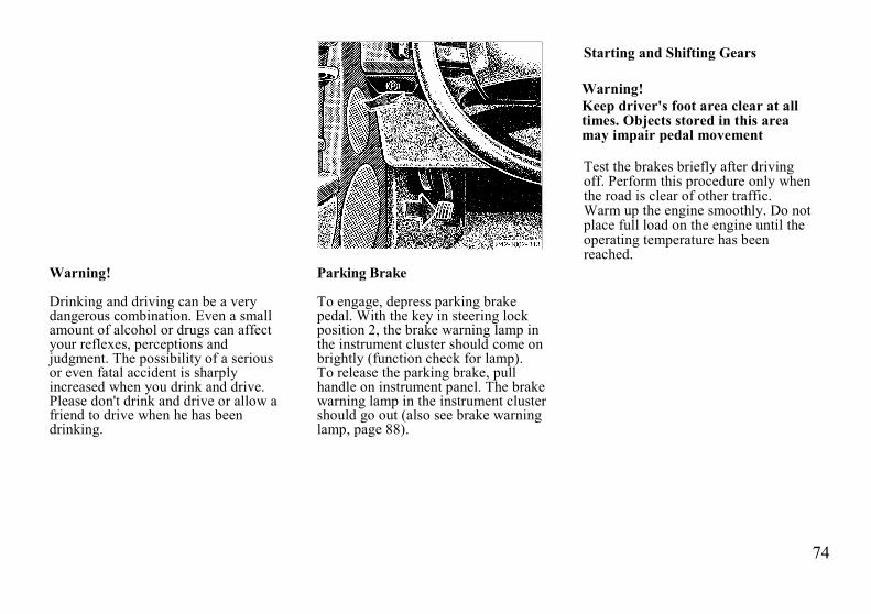
74
Starting and Shifting Gears
Warning!Keep driver's foot area clear at alltimes. Objects stored in this areamay impair pedal movement
Test the brakes briefly after drivingoff. Perform this procedure only whenthe road is clear of other traffic.Warm up the engine smoothly. Do notplace full load on the engine until theoperating temperature has beenreached.
Warning!
Drinking and driving can be a verydangerous combination. Even a smallamount of alcohol or drugs can affectyour reflexes, perceptions andjudgment. The possibility of a seriousor even fatal accident is sharplyincreased when you drink and drive.Please don't drink and drive or allow afriend to drive when he has beendrinking.
Parking Brake
To engage, depress parking brakepedal. With the key in steering lockposition 2, the brake warning lamp inthe instrument cluster should come onbrightly (function check for lamp).To release the parking brake, pullhandle on instrument panel. The brakewarning lamp in the instrument clustershould go out (also see brake warninglamp, page 88).
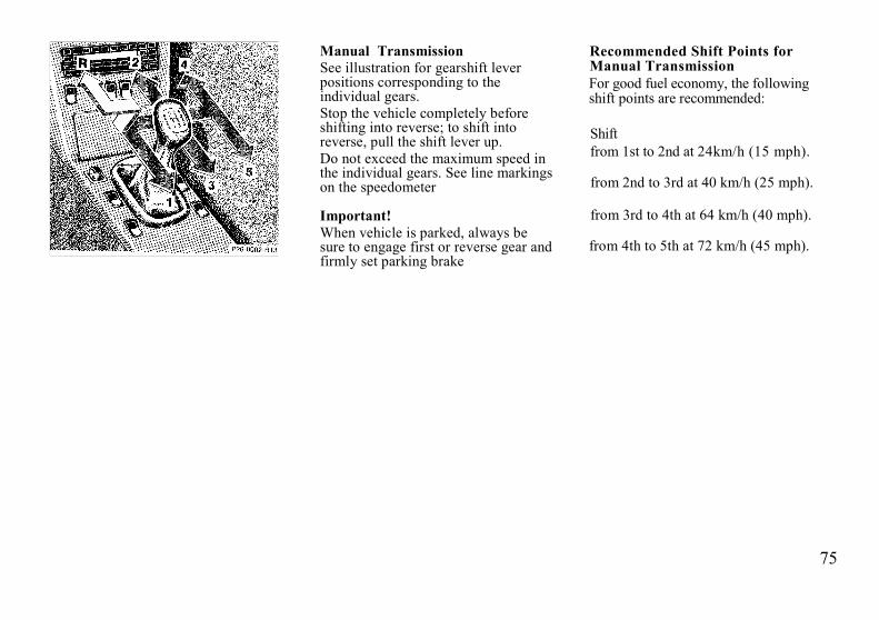
75
Manual TransmissionSee illustration for gearshift leverpositions corresponding to theindividual gears.Stop the vehicle completely beforeshifting into reverse; to shift intoreverse, pull the shift lever up.Do not exceed the maximum speed inthe individual gears. See line markingson the speedometer
Important!When vehicle is parked, always besure to engage first or reverse gear andfirmly set parking brake
Recommended Shift Points forManual TransmissionFor good fuel economy, the followingshift points are recommended:
Shiftfrom 1st to 2nd at 24km/h (15 mph).
from 2nd to 3rd at 40 km/h (25 mph).
from 3rd to 4th at 64 km/h (40 mph).
from 4th to 5th at 72 km/h (45 mph).
76
Automatic Transmission
The automatic transmissionselects individual gears auto-matically, dependent upon• Selector lever position• Accelerator position• Vehicle speed
Important!When parking the car and beforeworking on the vehicle with the enginerunning, firmly depress the parkingbrake pedal and shift the selector leverinto "P".
Driving
The selector lever is automaticallylocked while in position "P". To movethe selector lever out of position "P",the service brake pedal must be firmlydepressed before the shift lock willrelease.Shift selector lever to the desiredposition only when the engine is idlingnormally and the service brake isapplied. Do not release the brake untilready to drive. The vehicle mayotherwise start creeping when theselector lever is in drive or reverseposition.
Warning!It is dangerous to shift theselector lever out of "P" or"N" if the engine speed is higherthan idle speed. If your foot is not onthe brake pedal, the car couldaccelerate quickly forward or inreverse. You could lose control ofthe car and hit someone or some-thing. Only shift into gear when theengine is idling normally.
Accelerator position
Partial throttle = early upshifting =normal acceleration
Full throttle = later upshifting = rapidacceleration
Kickdown (depressing the acceleratorbeyond full throttle) = downshifting tonext lowest gear = maximumacceleration. Once the desired speed isattained, ease up on the accelerator -the transmission shifts up again.

77
Selector Lever Positions300 SLThe automatic gear shifting process canbe adapted to specific operatingconditions using the selector lever.
P Parking lock.The parking lock is an additionalsafeguard to the parking brake whenparking the vehicle. Engage onlywith the car stopped.
Note:The key can be removed from thesteering lock only with the selectorlever in position "P". With the keyremoved, the selector lever islocked in position "P".
R Reverse gear.Shift to reverse gear only with thecar stopped.
N Neutral.No power is transmitted from theengine to the rear axle. When thebrakes are released, the vehicle canbe moved freely (pushed or towed).Do not engage "N" while drivingexcept to coast when the vehicle isin danger of skidding (e.g. on icyroads, see page 19).
D The transmission automaticallyupshifts to 5th gear. Position "D"provides optimum drivingcharacteristics under all normaloperating conditions.
4 Upshift to 4th gear only.Suitable for performancedriving.
3 Upshift to 3rd gear only. Suitablefor moderately steep hills. Since thetransmission does not shift higherthan 3rd gear, this gear selectionwill allow use of the engine's brak-ing power downhill.
2 Upshift to 2nd gear only.For driving in mountainous regionsor under extreme operatingconditions. This gear selection willallow use of the engine's brakingpower when descending steepgrades.

78
Important!Do not exceed the vehicle speed limitsfor individual gear selections, whichare indicated by marks (I, II, III, etc.)on the circumference of thespeedometer.To avoid overrevving the engine, theselector lever cannot be moved to alower gear if the vehicle speed exceedsthe speed limit of that gear.Warning!On slippery road surfaces, neverdownshift in order to obtain brakingaction. This could result in rearwheel slip and reduced vehiclecontrol. Your vehicle's ABS will notprevent this type of loss of control.
To prevent the engine from laboringat low RPMs, do not allow the enginespeed to drop too low on uphillgradients.
Depending on the degree of the incline,shift selector lever to a lower gearearly enough to maintain engine RPMwithin the best torque range.StoppingFor brief stops, e.g. at traffic lights,leave the transmission in gear and holdvehicle with the service brake.For longer stops with the engine idling,shift into "N" or "P".When stopping the car on an uphillincline, do not hold it with theaccelerator, use the brake. This avoidsunnecessary transmission heat build up.
Warning!Getting out of your car with theselector lever not fully engaged inposition "P" is dangerous. Whenparked on a steep incline, position"P" alone may not prevent yourvehicle from rolling, possibly hittingpeople or objects. Always set theparking brake in addition to shiftingto position "P".
ManeuveringTo maneuver in tight areas, e.g. whenpulling into parking space, control thecar speed by gradually releasing thebrakes. Accelerate gently and neverabruptly step on the accelerator.To rock a car out of soft ground (mudor snow), alternately shift fromforward to reverse, while applyingslight partial throttle.Rocking a car free in this manner maycause the ABS warning lamp to comeon. Turn off and restart the engine toclear the malfunction indication.
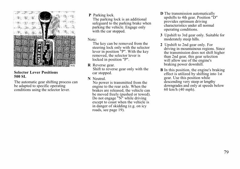
79
Selector Lever Positions500 SLThe automatic gear shifting process canbe adapted to specific operatingconditions using the selector lever.
P Parking lock.The parking lock is an additionalsafeguard to the parking brake whenparking the vehicle. Engage onlywith the car stopped.
Note:The key can be removed from thesteering lock only with the selectorlever in position "P". With the keyremoved, the selector lever islocked in position "P".
R Reverse gear.Shift to reverse gear only with thecar stopped.
N Neutral.No power is transmitted from theengine to the rear axle. When thebrakes are released, the vehicle canbe moved freely (pushed or towed).Do not engage "N" while drivingexcept to coast when the vehicle isin danger of skidding (e.g. on icyroads, see page 19).
D The transmission automaticallyupshifts to 4th gear. Position "D"provides optimum drivingcharacteristics under all normaloperating conditions.
3 Upshift to 3rd gear only. Suitable formoderately steep hills.
2 Upshift to 2nd gear only. Fordriving in mountainous regions. Sincethe transmission does not shift higherthan 2nd gear, this gear selectionwill allow use of the engine'sbraking power downhill.
B In this position, the engine's brakingeffect is utilized by shifting into 1stgear. Use this position whiledescending very steep or lengthydowngrades and only at speeds below60 km/h (40 mph).

80
Important!Do not exceed the vehicle speed limitsfor individual gear selections, whichare indicated by marks (I, II, III, etc.)on the circumference of thespeedometer.
Do not brake the vehicle bydownshifting to a lower gear (forexample from "D" to "3") unless thespeedometer needle is below the speedlimit mark of that particular gear range.Over-revving could result in seriousdamage to the engine.
Warning!On slippery road surfaces, neverdownshift in order to obtain brakingaction. This could result in rearwheel slip and reduced vehiclecontrol. Your vehicle's ABS will notprevent this type of loss of control.This applies particularly for position"B".
To prevent the engine from laboring atlow RPMs, do not allow the enginespeed to drop too low on uphillgradients.
Depending on the degree of the incline,shift selector lever to a lower gear earlyenough to maintain engine RPM withinthe best torque range.
StoppingFor brief stops, e.g. at traffic lights,leave the transmission in gear and holdvehicle with the service brake.For longer stops with the engine idling,shift into "N" or "P".When stopping the car on an uphillincline, do not hold it with theaccelerator, use the brake. This avoidsunnecessary transmission heat buildup.
Warning!Getting out of your car with theselector lever not fully engaged inposition "P" is dangerous. Whenparked on a steep incline, position"P" alone may not prevent yourvehicle from rolling, possibly hittingpeople or objects. Always set theparking brake in addition to shiftingto position "P".
ManeuveringTo maneuver in tight areas, e.g. whenpulling into parking space, control thecar speed by gradually releasing thebrakes. Accelerate gently and neverabruptly step on the accelerator.To rock a car out of soft ground (mudor snow), alternately shift fromforward to reverse, while applyingslight partial throttle.
Rocking a car free in this manner maycause the ABS warning lamp to comeon. Turn off and restart the engine toclear the malfunction indication.
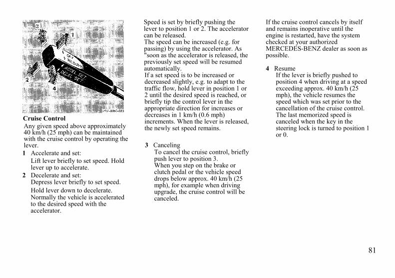
81
Cruise ControlAny given speed above approximately40 km/h (25 mph) can be maintainedwith the cruise control by operating thelever.1 Accelerate and set:
Lift lever briefly to set speed. Holdlever up to accelerate.
2 Decelerate and set:Depress lever briefly to set speed.Hold lever down to decelerate.Normally the vehicle is acceleratedto the desired speed with theaccelerator.
Speed is set by briefly pushing thelever to position 1 or 2. The acceleratorcan be released.The speed can be increased (e.g. forpassing) by using the accelerator. As"soon as the accelerator is released, thepreviously set speed will be resumedautomatically.If a set speed is to be increased ordecreased slightly, e.g. to adapt to thetraffic flow, hold lever in position 1 or2 until the desired speed is reached, orbriefly tip the control lever in theappropriate direction for increases ordecreases in 1 km/h (0.6 mph)increments. When the lever is released,the newly set speed remains.
3 CancelingTo cancel the cruise control, brieflypush lever to position 3.When you step on the brake orclutch pedal or the vehicle speeddrops below approx. 40 km/h (25mph), for example when drivingupgrade, the cruise control will becanceled.
If the cruise control cancels by itselfand remains inoperative until theengine is restarted, have the systemchecked at your authorizedMERCEDES-BENZ dealer as soon aspossible.
4 ResumeIf the lever is briefly pushed toposition 4 when driving at a speedexceeding approx. 40 km/h (25mph), the vehicle resumes thespeed which was set prior to thecancellation of the cruise control.The last memorized speed iscanceled when the key in thesteering lock is turned to position 1or 0.

82
Note:If the engine does not brake the vehiclesufficiently while driving on adowngrade, the speed you set on thecruise control may be exceeded andyou may have to step on the brakepedal to slow down. As soon as thegrade eases, the cruise controlled speedwill again be maintained as long as thebrakes were not previously applied, orthe lever may be used to resume thepreviously set speed if the brakes wereapplied.
Warning!Only use the cruise control if thetraffic and weather conditions makeit advisable to travel at a steadyspeed.
• The use of cruise controlcan be dangerous on windingroads or in heavy traffic becauseconditions do not allow safedriving at a steady speed.
• The use of cruise controlcan be dangerous on slipperyroads. Rapid changes in tireadhesion can result in wheel spinand loss of control.
The "Resume" function should onlybe operated if the driver is fullyaware of the previously set speed andwishes to resume this particularpreset speed.
Caution!In the case of manual transmissions,the vehicle maximum speed in theindividual gears should not beexceeded. See line markings on thespeedometer. In the case of automatictransmissions, the selector lever mustnot be shifted to position "N" whendriving with cruise control engaged asotherwise the engine will overrev,possibly causing serious enginedamage.

83
Charge Indicator Lamp
Should the charge indicator lamp fail tocome on prior to starting when the keyis in steering lock position 2 or shouldit fail to go out after starting or duringoperation, this indicates a fault whichmust be repaired at an authorizedMERCEDES-BENZ dealerimmediately.
If the charge indicator lamp comes onwhile the engine is running, this mayindicate that the poly-V-belt hasbroken. Should this condition occur,the poly-V-belt must be replaced beforecontinuing to operate the vehicle.Otherwise, the engine will overheat dueto an inoperative water pump whichmay result in damage to the engine.
Oil Pressure Gauge withOil Pressure Warning Lamp
With the key in steering lock position2, the oil pressure warning lamp comeson and goes out with the enginerunning.
The oil pressure at idle speed may dropif the engine is at operatingtemperature. This will not jeopardizethe engine's operational reliability.Pressure must, however, riseimmediately upon acceleration.
Note:If the oil pressure warning lamp doesnot go out after starting the engine orcomes on while driving and the oilpressure gauge needle drops to "0",then damage to the engine may occurwith continued operation. Turn offengine immediately and contact anauthorized MERCEDES-BENZ dealer.Do not operate the car until thecondition is repaired.
There is no need for concern should theoil pressure warning lamp light upbriefly, (for example, in sharp turns orhard braking) provided the lamp goesout immediately. We recommend youto drive to the nearest service stationwhere the engine oil should be toppedto the "full" mark on the dipstick withan approved oil.
84
Low Engine Oil Level WarningLampWith the key in steering lock position2, the oil pressure warning lamp comeson and goes out with the enginerunning.
If the warning lamp comes on with theengine running and at operatingtemperature, the engine oil level hasdropped to approximately theminimum mark on the dipstick.
When this occurs, the warning lampwill first come on intermittently andthen stay on if the oil level dropsfurther.
If no oil leaks are noted and there isindicated engine oil pressure, continueto drive to the nearest service stationwhere the engine oil should be toppedto the "full" mark on the dipstick withan approved oil.
In addition to the warning lamp, theengine oil level should be periodicallychecked with the dipstick, for exampleduring a fuel stop, or before a long trip.See page 98.
Engine Oil ConsumptionEngine oil consumption checks shouldonly be made after the break-in period.During the break-in period, higher oilconsumption may be noticed and isnormal. Frequent driving at highengine speeds results in increasedconsumption.
Fuel Consumption GaugeWhile driving, instantaneous fuelconsumption is indicated in miles pergallon (mpg), or in Canada liters per100 kilometers (I/100 km).
With the engine switched off, theneedle reads "0".
At idle speed, maximum consumptionis indicated.

85
Fuel Reserve Warning LampWith the key in steering lock position2, the fuel reserve warning lamp comeson and goes out with the enginerunning.
If the warning lamp does not go outafter starting the engine or if it comeson while driving, it indicates that thefuel level is down to the reservequantity of approx. 10 liters (2.6 gal).
Outside Temperature IndicatorThe temperature sensor is located in thefront bumper area. Due to its location,the sensor can be affected by road orengine heat during idling or slowdriving. This means that the accuracyof the displayed temperature can onlybe verified by comparison to athermometer placed next to the sensor,not by comparison to external displays(e.g. bank signs, etc.).
Adaptation to ambient temperaturetakes place in steps and depends on theprevailing driving conditions (stop-and-go or moderate, constant driving) andamount of temperature change.
Warning!The outside temperature indicator isnot designed to serve as an Ice-Warning Device and is therefore un-suitable for that purpose. Indicatedtemperatures just above the freezingpoint do not guarantee that the roadsurface is free of ice.
Coolant Temperature GaugeIf the antifreeze mixture is effective to- 30°C (- 22°F), the boiling point ofthe coolant in the pressurized coolingsystem of your vehicle is approx.130°C (266 °F).
During severe operating conditions andstop-and-go city traffic, the coolanttemperature may rise close to the redmarking.
The engine should not be operated withthe coolant temperature in the red zone.
Warning!• Driving when your engine is badly
overheated can cause some fluidswhich may have leaked into theengine compartment to catch fire.You could be seriously burned.Turn off the engine and get out ofthe car until it cools down.
• Steam from an overheated enginecan cause serious burns and canoccur just by opening the enginehood. Stay away from the engine ifyou see or hear steam comingfrom it. Turn off the engine and donot stand near the car until itcools down.
86
Low Engine Coolant LevelWarning LampWith the key in steering lock position2, the warning lamp comes on and goesout with the engine running.If the warning lamp does not go outafter starting the engine, or if it comeson while driving, then the coolant levelhas dropped below the required level.If no leaks are noticeable and theengine temperature does not increase,continue to drive to the nearest servicestation and have coolant added to thecoolant system. See page 95.
In cases of major or frequent minorcoolant loss, have the cooling systemchecked at your authorizedMERCEDES-BENZ dealer as soon aspossible.
Note:Do not drive without coolant in thecooling system. The engine canoverheat causing major engine damage.Monitor the coolant temperature gaugewhile driving.
Warning!Do not spill antifreeze on hot engineparts. Antifreeze contains ethyleneglycol which may burn if it comesinto contact with hot engine parts.You can be seriously burned.
Low Windshield and HeadlampWasher Fluid Level Warning LampWith the key in steering lock position2, the warning lamp comes on and goesout with the engine running. If thewarning lamp comes on with theengine running, the level of thereservoir has dropped to approx. 1/4 ofthe total volume. The reservoir shouldbe refilled with MB WindshieldWasher Concentrate "S" and water (orcommercially available premixedwindshield washer solvent/antifreeze,depending on ambient temperature -see page 51) at the next opportunity.The reservoir for the windshield andheadlamp washer system is located inthe engine compartment. See page 144.
Roll Bar Warning LampWith the key in steering lock position2, the warning lamp comes on and goesout with the engine running.
Warning!If the warning lamp does not go outafter starting the engine, or if itcomes on while driving, and theindicator lamps in the roll bar switchblink simultaneously, then the rollbar system is defective and may notactivate in an accident. In this case,raise the roll bar manually (see page62) before continuing to drive.
Have the roll bar system checked atyour authorized MERCEDES-BENZdealer as soon as possible.

87
Seat Belt and Backrest LockWarning LampWith the key in steering lock position2, the warning lamp comes on.
After starting the engine, the warninglamp blinks for a brief period toremind the driver and passenger tofasten seat belts before driving off.
If the warning lamp does not go putafter blinking briefly, but is instead litcontinuously, then a backrest is notengaged in its lock. In this case anaudible warning will sound for approx.20 seconds when starting to drive.
The warning lamp goes out as soon asthe backrest is engaged in its lock.
If the backrest is locked and thewarning lamp does not go out, have thesystem checked at your authorizedMERCEDES-BENZ dealer as soon aspossible.
Exterior Lamp Failure IndicatorLampWith the key in steering lock position2, a dim indicator lamp comes on andgoes out with the engine running.
With the key in steering lock position 2or with the engine running, a brightillumination of this lamp indicates anexterior lamp failure.
Note:The indicator lamp will also come on ifan incorrect bulb is installed.
If additional lighting equipment isinstalled (e.g. auxiliary headlamps etc.)be certain to connect into the fusebefore the failure indicator monitoringunit in order to avoid damaging thesystem.
If an exterior lamp fails, the in-dicator lamp will come on onlywhen that lamp is switched on.
If a brake or turn signal lamp fails, thelamp failure indicator will come onwhen applying the brake or actuatingthe turn signal and stay on until theengine is turned off.
88
Brake Pad Wear Indicator LampThe brake pad wear indicator lamp inthe instrument cluster comes on whenthe key in the steering lock is turned toposition 2 and goes out when theengine is running.
If the indicator lamp lights up duringbraking, this indicates that the frontwheel brake pads are worn down.
Have the brake system checked at yourauthorized MERCEDES-BENZ dealeras soon as possible.
Brake Warning LampThe brake warning lamp will come on:
• when there is insufficient brakefluid in the reservoir (enginerunning and parking brake released)
• when the parking brake is set(engine running)
• as a lamp function check (key insteering lock position 2).
When the minimum mark on thereservoir is reached, have the brakesystem checked for brake pad thicknessand leaks.
Warning!Driving with the brake warninglamp on can result in an accident.Have your brake system checkedimmediately if the brake warninglamp stays on. Don't add brake fluidbefore checking the brake system.Overfilling the brake fluid reservoircan result in spilling brake fluid onhot engine parts and the brake fluidcatching fire. You can be seriouslyburned.
89
ABS (Antilock Brake System)The ABS prevents the wheels fromlocking up above a vehicle speed ofapproximately 3 km/h (2 mph)independent of road surface conditions.It is necessary, however, that thevehicle speed reaches at least 8 km/h(5 mph) before commencing to brake.
At the instant one of the wheels isabout to lock up, a slight pulsation canbe felt in the brake pedal, indicatingthat the ABS is in the regulating mode.
On slippery road surfaces, the ABS willrespond even with only slight brakepedal pressure. The pulsating brakepedal can be an indication of hazardousroad conditions and functions as areminder to take extra care whiledriving.
The ABS warning lamp in theinstrument cluster comes on with thekey in steering lock position 2 andshould go out with the engine running.
If the charging voltage falls below 10volts, the warning lamp comes on andthe ABS is switched off. When thevoltage is above this value again, thewarning lamp should go out and theABS will be operational.
If the ABS warning lamp does not goout or comes on while driving, itindicates that the ABS has detected amalfunction and has switched off. Inthis case, the brake system functions inthe usual manner, but without antilockassistance.
Have the system checked at yourauthorized MERCEDES-BENZ dealeras soon as possible.
Warning!Even the ABS cannot prevent thenatural laws of physics from actingon the vehicle. The ABS cannotprevent accidents, including thoseresulting from excessive speed inturns, following another vehicle tooclosely, or aquaplaning. Only a safe,attentive, and skillful driver canprevent accidents. The capabilities ofan ABS equipped car must never beexploited in a reckless or dangerousmanner which could jeopardize theuser's safety or the safety of others.
90
Emission Control
Certain systems of the engine serve tokeep the toxic components of theexhaust gases within permissible limitsrequired by law.
These systems, of course, will functionproperly only when maintained strictlyaccording to factory specifications.Any adjustments on the engine should,therefore, be carried out only byqualified MERCEDES-BENZtechnicians. Engine adjustments shouldnot be altered in any way. Moreover,the specified service and maintenancejobs must be carried out regularlyaccording to MERCEDES-BENZservicing requirements. For detailsrefer to the Maintenance Booklet.
Warning!Inhalation of exhaust gas ishazardous to your health. Allexhaust gas contains carbonmonoxide, and inhaling it can causeunconsciousness and lead to death.
Do not run the engine in confinedareas (such as a garage) which arenot properly ventilated. If you thinkthat exhaust gas fumes are enteringthe vehicle while driving, have thecause determined and corrected im-mediately. If you must drive underthese conditions, drive only with atleast one window fully open.
On-Board Diagnostic System(California models only)
The CIS-E control unit monitorsemission control components thateither provide input signals to orreceive output signals from the controlunit. Malfunctions resulting frominterruptions or failure of any of thesecomponents are indicated by the"CHECK ENGINE" indicator lamp inthe instrument cluster and aresimultaneously stored in the CIS-Econtrol unit.
If the "CHECK ENGINE" indicatorlamp comes on, have the systemchecked at your authorizedMERCEDES-BENZ dealer as soon aspossible.
An on-board test connection withpushbutton and light emitting diode(LED) is located on the enginecompartment firewall, allowing theaccurate detection of systemmalfunctions.

91
Traveling AbroadAbroad, there is a widely-spreadMERCEDES-BENZ service network atyour disposal. If you plan to travel intoareas which are not listed in the index ofyour dealer directory, you shouldrequest pertinent information fromyour authorized MERCEDES-BENZdealer.Winter DrivingHave your car winterized at yourauthorized MERCEDES-BENZ dealerbefore the onset of winter.• Change the engine oil if the engine
contains an oil which is notapproved for winter operation. Forviscosity (SAE class) and fillingquantity, see "Fuels, Coolants,Lubricants, etc." page 133.
• Check engine coolantanticorrosion/antifreezeconcentration.
• Additive for the windshield washerand headlamp cleaning system: AddMB Concentrate "S" to a premixedwindshield washer solvent/antifreeze which is formulated forbelow freezing temperatures (seepage 51).
• Test battery: Battery capacity dropswith decreasing ambienttemperature. A well charged batteryensures that the engine can alwaysbe started, even at low ambienttemperatures.
• Tires: We recommend M + S radialtires on all four wheels for thewinter season. Observe permissiblemaximum speed for M + S radialtires and the legal speed limit.
Note:In winter operation, the maximumefficiency of the acceleration slipcontrol or of the automatic lockingdifferential is only achieved with M + Sradial tires.
Snow ChainsUse only snow chains that are testedand recommended by MERCEDES-BENZ. Your authorized MERCEDES-BENZ dealer will be glad to advise youon this subject.Chains should only be used on the rearwheels. Follow the manufacturer'smounting instructions.After driving a short distance, retightenthe mounted chains.Snow chains should only be driven onsnow covered roads at speeds not toexceed 50 km/h (30 mph). Removechains as soon as possible whendriving on roads without snow.For tips on driving on slippery winterroads, refer to page 19.

92

93
Practical Hints

94
HoodTo open:To unlock the hood, pull release lever(1) under the driver's side of theinstrument panel.
Pull handle (2) out of radiator grill tostop and open hood. Do not lift hood atlouvers of grill! Make certain thewindshield wiper arm is not foldedforward.
To close:Lower hood and let it drop into lockfrom a height of approx. 30 cm (1 ft).Do not press down on hood with hands.
Warning!To help prevent personal injury,stay clear of moving parts when thehood is open and the engine isrunning. Be sure the hood isproperly closed before driving.The engine is equipped with atransistorized ignition system.Because of the high voltage it isdangerous to touch any components(ignition coil, distributor, spark plugsockets, ignition cables, diagnosticsocket) of the ignition system:• with the engine running,• while starting the engine,• if the ignition is "on" and the
engine is turned manually.

95
Checking Coolant LevelThe coolant level can be checkedvisually at the transparent coolantreservoir.To check the coolant level, the vehiclemust be parked on level ground.Check coolant level only when coolantis cold:The coolant should reach the rib in thefiller neck. Also see marking (1) onreservoir.
Warning!• Use extreme caution when opening
the hood if there are any signs ofsteam or coolant leaking from thecooling system.
• Do not remove pressure cap oncoolant reservoir if enginetemperature is above 90°C(194°F). Allow engine to cool downbefore removing cap. The coolantreservoir contains hot fluid and isunder pressure.
• Using a rag, turn cap to first notchto relieve excess pressure. Ifopened immediately, hot scaldingfluid and steam will be blown outunder pressure, possibly causingpersonal injury,
• Do not spill antifreeze on hotengine parts. Antifreeze containsethylene glycol which may burn ifit comes into contact with hotengine parts. You can be seriouslyburned.
Adding Coolant.If coolant has to be added, a 50/50mixture of water and MBanticorrosion / antifreeze should beadded.
300 SL:The drain plugs for the cooling systemare located on the right side of theengine block and" at the bottom of theradiator.
500 SL:The drain plugs for the cooling systemare located on the right and left sidesof the engine block and at the bottomof the radiator.Anticorrosion/antifreeze, see"Fuels, Coolants, Lubricants,etc.", page 137.

96
300 SL
Checking Engine Oil Level1 Oil dipstick2 Oil filler cap
500 SL
The best time to check the engineoil level is when the oil is warm, suchas during a fuel stop.
With the vehicle on level ground, stopthe engine and wait a few minutes forthe oil to drain back to the oil pan.
Wipe the dipstick clean beforechecking.
Add oil, if needed, only tothe upper mark (max). Donot overfill engine.
For viscosity and capacity, see"Fuels, Coolants , Lubricants,etc. page 133.For low engine oil level warning lamp,see page 84.
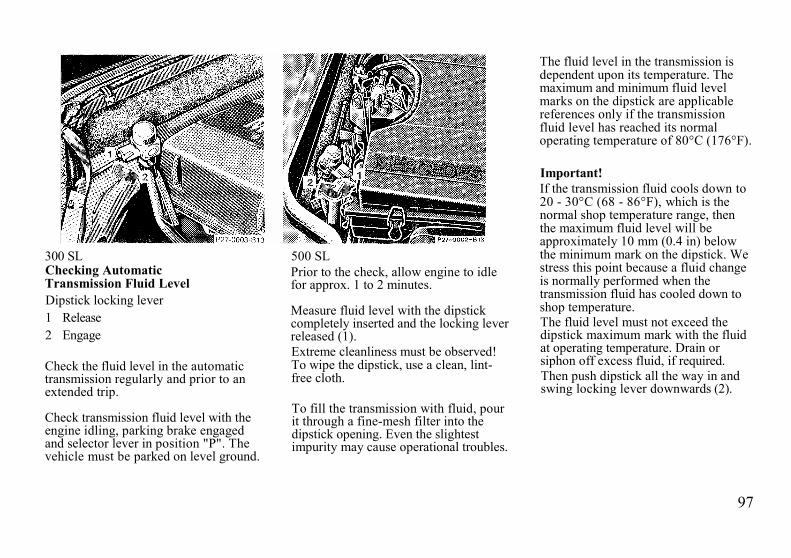
97
300 SLChecking AutomaticTransmission Fluid LevelDipstick locking lever1 Release2 Engage
Check the fluid level in the automatictransmission regularly and prior to anextended trip.
Check transmission fluid level with theengine idling, parking brake engagedand selector lever in position "P". Thevehicle must be parked on level ground.
500 SLPrior to the check, allow engine to idlefor approx. 1 to 2 minutes.
Measure fluid level with the dipstickcompletely inserted and the locking leverreleased (1).Extreme cleanliness must be observed!To wipe the dipstick, use a clean, lint-free cloth.
To fill the transmission with fluid, pourit through a fine-mesh filter into thedipstick opening. Even the slightestimpurity may cause operational troubles.
The fluid level in the transmission isdependent upon its temperature. Themaximum and minimum fluid levelmarks on the dipstick are applicablereferences only if the transmissionfluid level has reached its normaloperating temperature of 80°C (176°F).
Important!If the transmission fluid cools down to20 - 30°C (68 - 86°F), which is thenormal shop temperature range, thenthe maximum fluid level will beapproximately 10 mm (0.4 in) belowthe minimum mark on the dipstick. Westress this point because a fluid changeis normally performed when thetransmission fluid has cooled down toshop temperature.The fluid level must not exceed thedipstick maximum mark with the fluidat operating temperature. Drain orsiphon off excess fluid, if required.Then push dipstick all the way in andswing locking lever downwards (2).
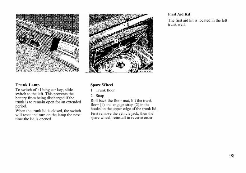
98
Trunk LampTo switch off: Using car key, slideswitch to the left. This prevents thebattery from being discharged if thetrunk is to remain open for an extendedperiod.When the trunk lid is closed, the switchwill reset and turn on the lamp the nexttime the lid is opened.
Spare Wheel1 Trunk floor2 StrapRoll back the floor mat, lift the trunkfloor (1) and engage strap (2) in thehooks on the upper edge of the trunk lid.First remove the vehicle jack, then thespare wheel; reinstall in reverse order.
First Aid KitThe first aid kit is located in the lefttrunk well.

99
1 Jack arm2 Jack base3 Tool kit
Vehicle JackSee illustration for proper storage ofjack.Before storing the jack, the jack arm(1) must be lowered almost to the base(2) of the jack.
Note:First remove the vehicle jack, then thespare wheel; reinstall in reverse order.
Warning!The jack is designed exclusively forjacking up the vehicle at the jacktubes built into either side of thevehicle. Use the jack only to lift thevehicle during a wheel change.Never get beneath the vehicle whileit is supported by the jack. Keephands and feet away from the areaunder the lifted vehicle. Alwaysfirmly set parking brake and blockwheels before raising vehicle withjack.
Do not disengage parking brakewhile the vehicle is raised. Be certainthat the jack is always vertical whenin use, especially on hills. Lower thevehicle onto sufficient capacityjackstands before working under thevehicle.
Vehicle ToolsThe vehicle tools (3) are located belowthe jack.
WheelsReplace rims or tires with the samedesignation, manufacturer and type asshown on the original part. See yourauthorized MERCEDES-BENZ dealerfor further information.
Warning!Do not mix different tire con-struction types (i.e. radial, bias, andbias-belted) on your car becausehandling may be adversely affectedand may result in loss of control.
See your authorized MERCEDES-BENZ dealer for information on testedand recommended rims and tires forsummer and winter operation. They canalso offer advice concerning tire serviceand purchase.

100
Tire ReplacementFront tires should be replaced in sets.Furthermore - in the event of tirereplacement - the spare wheel, ifpossible, should be used on the rearaxle. Rims and tires must be of thesame size. For dimensions, see"Technical Data".We recommend that you break in newtires for approx. 100 km (60 miles) atmoderate speed. It is imperative that thewheel mounting bolts be retightenedafter approx. 100 to 500 km (60 -300miles).On new vehicles retightening is carriedout during the 1st inspection.Retightening is also necessarywhenever wheels are fitted, e.g. whenthe spare wheel is used for the firsttime or when a set of wheels with M +8 tires is installed.Tightening torque: 110 Nm(80 ft. lb.)".For rim and tire specifications, refer to"Technical Data".
Warning!Worn, old tires can cause accidents.If the tire tread is badly worn, or ifthe tires have sustained damage,replace them.
When replacing rims, use onlygenuine MERCEDES-BENZ wheelbolts (identified by Mercedes star)specified for the rim type.Failure to do so can result in thebolts loosening and possibly anaccident
Rotating WheelsThe wheels can be rotated according tothe degree of tire wear while retainingthe same direction of travel.Rotating, however, should be carriedout at a mileage of 5000-10000 km(3000-6000 miles), before the charac-teristic tire wear pattern (shoulder wearon front wheels and tread center wearon rear wheels) becomes visible, asotherwise the driving propertiesdeteriorate.
Note:Thoroughly clean the inner side of thewheels any time you rotate the wheelsor wash the vehicle underside.The use of retread tires is notrecommended. Retread tires mayadversely affect the handlingcharacteristics and safety of thevehicle.Dented or bent rims cause tire pressureloss and damage to the tire beads. Forthis reason, check rims for damage atregular intervals.The rim flanges must be checked forwear before a tire is mounted. Removeburrs, if any.

101
Warning!The jack is designed exclusively forjacking up the vehicle at the jacktubes built into either side of thevehicle. Use the jack only to lift thevehicle during a wheel change. Neverget beneath the vehicle while it issupported by the jack. Keep handsand feet away from the area underthe lifted vehicle. Always firmly setparking brake and block wheelsbefore raising vehicle with jack.Do not disengage parking brakewhile the vehicle is raised. Be certainthat the jack is always vertical whenin use, especially on hills. Lower thevehicle onto sufficient capacityjackstands before working under thevehicle.
Changing WheelsMove vehicle to a level area which is asafe distance from the roadway.1. Set parking brake and turn on
hazard warning flasher.2. Select 1st or reverse gear in vehicles
with manual transmission orposition "P" in vehicles equippedwith automatic transmission.
3. Prevent vehicle from rolling away byblocking wheels with wheel chocksor sizable wood block or stone (notsupplied with, vehicle). Whenchanging a wheel on a hill, placechocks on the downhill sideblocking both wheels of the otheraxle. On a level road, place onechock in front of and one behind thewheel that is diagonally opposite tothe wheel being changed.
4. Unfold wrench, loosen but do notremove the wheel bolts yet.

102
5. Remove the protective cover fromthe jack support tube opening byinserting a screwdriver in theopening and prying it out.The tube openings are locateddirectly behind the front wheelhousings and in front of the rearwheel housings.
6. Insert jack arm fully into thetube hole up to the stop.Position the jack so that it isalways vertical (plumb-line) asseen from the side (see arrow),even if the vehicle is parked onan incline.
7. Jack up the vehicle until thewheel is clear of the ground.
8. Unscrew wheel bolts completely.Keep bolt threads protected fromdirt and sand.While removing the last bolt, holdwheel against hub to avoid paintdamage on rim.
9. Remove wheel.10. Screw the alignment bolt (1)
supplied in the tool kit into theupper-most threaded hole.

103
11. Install spare wheel on wheelhub. Insert wheel bolts andtighten them slightly.To avoid paint damage, placewheel flat against hub and hold itthere while installing first wheelbolt.Unscrew the alignment bolt toinstall the last wheel bolt.
12. Lower car. Remove jack andinsert jack tube cover.
13. Fold wrench together andtighten the five bolts evenly,following the sequenceillustrated above, until all boltsare tight.Observe a tightening torque of 110Nm (80 ft. lb.).
14. Correct tire pressure.Important!When installing new wheels themounting bolts must be retightenedafter approx. 100 to 500 km (60 - 300miles).
Before storing the jack, the jack armmust be lowered almost to the base ofthe jack. Store the spare wheel first andthen the vehicle jack.
Warning!Incorrect mounting bolts orimproperly tightened mounting boltscan cause the wheel to come off. Thiscould cause an accident Be sure touse the correct mounting bolts.

104
Tire Inflation PressureA table (see fuel filler flap) lists the tireinflation pressures specified forsummer and winter tires as well as forthe varying operating conditions.
Important!Tire pressure differs by approx.0.1 bar (1.5 psi) per 10°C (18°F)of air temperature change. Keepthis in mind when checking tirepressure inside a garage especially inthe winter.
Example:If garage temperature = approx. + 20°C( + 68°F) and ambient temperature =approx. 0°C ( + 32°F) then the adjustedair pressure = specified air pressure +0.2 bar (+ 3 psi).Tire pressures listed for light loads areminimum values offering high drivingcomfort.Increased inflation pressures for heavyloads produce favorable handlingcharacteristics with lighter loads andare perfectly permissible. The ride ofthe vehicle, however, will becomesomewhat harder.
Tire temperature and pressure increasewith the vehicle speed.Tire pressure should therefore only becorrected on cold tires.
Correct tire pressure in warm tires onlyif pressure has dropped below thepressure listed in the table and therespective operating conditions aretaken into consideration.
An underinflated tire due to a slowleak (e.g. due to a nail in the tire) maycause damage such as tread separation,bulging, etc.. Regular tire pressurechecks (including the spare tire) atintervals of no more than 14 days aretherefore essential.If a tire constantly loses air, it shouldbe inspected for damage.
Warning!Do not overinflate tires,Overinflating tires can result insudden deflation (blow-out) becausethey are more likely to becomepunctured or damaged by roaddebris, potholes, etc. Follow recom-mended inflation pressures.Do not overload the tires byexceeding the specified vehiclecapacity weight (as indicated by thelabel on the driver's door latch post).Overloading the tires can overheatthem, possibly causing a blow-out.

105
BatteryThe maintenance-free battery is locatedin the trunk behind the right-handcover panel.
The service life of the battery isdependent on its condition of charge.The battery must always be sufficientlycharged for it to last an optimum lengthof time.
Therefore, we recommend that youhave the battery charge checkedfrequently if you use the vehicle mostlyfor short distance trips, or if it is notused for long periods of time.
Only charge a battery with a batterycharger after it has been disconnectedfrom the vehicle electrical circuit.
When removing and connecting thebattery, always make sure that allelectrical consumers are off and thekey is in steering lock position O.While the engine is running the batteryterminal clamps must not be loosenedor detached as otherwise the alternatorand other electronic components wouldbe damaged.
Warning!Never lean over batteries whileconnecting or jump starting, youmight get injured.
Battery fluid contains sulfuric acid.Do not allow this fluid to come incontact with eyes, skin or clothing.In case it does, immediately flushaffected area with water and seekmedical help.
A battery will also producehydrogen gas, which is flammableand explosive. Keep flames or sparksaway from battery, avoid improperconnection of jumper cables,smoking, etc..
Batteries contain enoughelectricity to burn you. Never touchuninsulated battery connections.

106
Spark PlugsRemove and install spark plugs onlywith socket wrench from the vehicletool kit.Tightening torque: 25 - 30 Nm (18 -22ft.lb.).For approved spark plugs see"Technical Data".
FusesIn engine compartment:1 Main fuse box2 Auxiliary fuse box
In trunk on rear wall:3 Auxiliary fuse box
Before replacing a blown fuse,determine the cause of the short circuit
Spare fuses are supplied insidethe fuse box. Observe amperage andcolor of fuse.
Always use a new fuse forreplacement. Never attempt torepair or bridge a blown fuse.
After replacing a blown fuse, closefuse box cover.

107
Headlamp AdjustmentCorrect headlamp adjustment isextremely important. Check andreadjust headlamps at regular intervalsand when a bulb has been replaced.
Replacing BulbsDo not touch glass portion of bulb withbare hands. Use plain paper or a cleancloth.Install only 12 volt bulbs with thespecified watt rating.
Headlamp Assembly1 Headlamp horizontal adjustment
screw2 Headlamp vertical adjustment
screw3 High and low beam headlamp
cover4 Squeeze latches for high and
low beam headlamp cover5 Turn signal, parking, side
marker and standing lamp bulb
6 Electrical connector for highand low beam headlamp bulb
7 Clamping ring for high and lowbeam headlamp bulb
Warning!Halogen lamps contain pressurizedgas. A bulb can explode if you:• Touch or move it when hot• Drop the bulb.• Scratch the bulb

108
Replacing bulbs:Bulb for turn signal, parking, sidemarker and standing lamp' (21/5W/32/3cp):
Turn bulb socket (5) with bulbcounterclockwise and pull out. Pushbulb into socket, turn counterclockwiseand remove.Bulb for high and low beam(Halogen type 9004):
Squeeze latches (4) and remove cover(3) upwards. Pull off electricalconnector (6). Turn clamping ring (7)counterclockwise and pull out bulbtogether with clamping ring. Removebulb.
Insert new bulb (flat side facing up),mount clamping ring (7) (with tabfacing down) and turn clock-wise. Pushelectrical connector on securely.
Taillamp Assemblies1 Side marker lamp
(10 W/6 cp bulb)2 Turn signal lamp3 Tail, parking and standing lamp
(21 W/32 cp bulb)4 Driver's side:
Tail, parking, standing and rear foglamp (21/4W/35/1.2cp bulb)Backup lamp(21 W/32 cp bulb)
5 Stop lamp(21 W/32 cp bulb)
To replace bulbs:Push the locking button (1) on the rearof the lamp support inward and swingopen lamp support. Push down the bulbto be changed, turn to the left andremove.
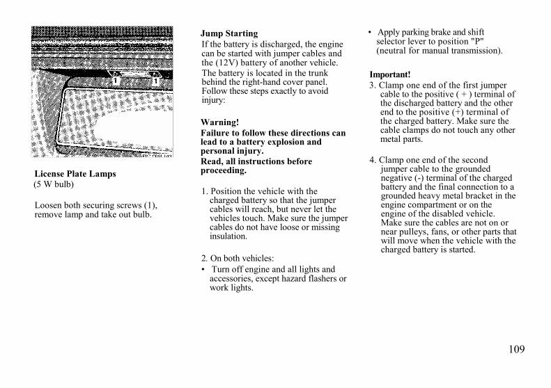
109
License Plate Lamps(5 W bulb)
Loosen both securing screws (1),remove lamp and take out bulb.
Jump StartingIf the battery is discharged, the enginecan be started with jumper cables andthe (12V) battery of another vehicle.The battery is located in the trunkbehind the right-hand cover panel.Follow these steps exactly to avoidinjury:
Warning!Failure to follow these directions canlead to a battery explosion andpersonal injury.Read, all instructions beforeproceeding.
1. Position the vehicle with thecharged battery so that the jumpercables will reach, but never let thevehicles touch. Make sure the jumpercables do not have loose or missinginsulation.
2. On both vehicles:• Turn off engine and all lights and
accessories, except hazard flashers orwork lights.
• Apply parking brake and shiftselector lever to position "P"(neutral for manual transmission).
Important!3. Clamp one end of the first jumper
cable to the positive ( + ) terminal ofthe discharged battery and the otherend to the positive (+) terminal ofthe charged battery. Make sure thecable clamps do not touch any othermetal parts.
4. Clamp one end of the secondjumper cable to the groundednegative (-) terminal of the chargedbattery and the final connection to agrounded heavy metal bracket in theengine compartment or on theengine of the disabled vehicle.Make sure the cables are not on ornear pulleys, fans, or other parts thatwill move when the vehicle with thecharged battery is started.

110
5. Start engine of the vehicle withthe charged battery and run athigh idle. Then start engine ofthe disabled vehicle in the usualmanner
6. After the engine has started,remove jumper cables byreversing the above installationsequence exactly, starting withthe jumper cable connected toa heavy metal bracket in thedisabled vehicle's enginecompartment. When removing eachclamp, make sure that it does nottouch any other metal while theother end is still attached.
Important!A discharged battery can freeze atapprox. -10°C (+ 14°F). In that case,it must be thawed out before jumpercables are used.Jumper cable specifications:• Minimum cable cross-section of 25
mm2 or approx. 2 AWG• Maximum length of 3500 mm
(11.5ft).
Warning!Never lean over batteries whileconnecting or jump starting, youmight get injured.
Battery fluid contains sulfuric acid.Do not allow this fluid to come incontact with eyes, skin or clothing.In case it does, immediately flushaffected area with water, and seekmedical help.
A battery will also producehydrogen gas, which is flammableand very explosive. Keep flames orsparks away from battery, avoidimproper connection of jumpercables, smoking, etc..
Batteries contain enough electricityto burn you. Never touchuninsulated battery connections.
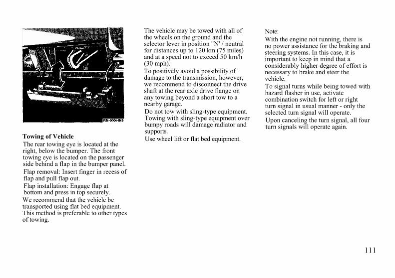
111
Towing of VehicleThe rear towing eye is located at theright, below the bumper. The fronttowing eye is located on the passengerside behind a flap in the bumper panel.Flap removal: Insert finger in recess offlap and pull flap out.Flap installation: Engage flap atbottom and press in top securely.We recommend that the vehicle betransported using flat bed equipment.This method is preferable to other typesof towing.
The vehicle may be towed with all ofthe wheels on the ground and theselector lever in position "N' / neutralfor distances up to 120 km (75 miles)and at a speed not to exceed 50 km/h(30 mph).To positively avoid a possibility ofdamage to the transmission, however,we recommend to disconnect the driveshaft at the rear axle drive flange onany towing beyond a short tow to anearby garage.Do not tow with sling-type equipment.Towing with sling-type equipment overbumpy roads will damage radiator andsupports.Use wheel lift or flat bed equipment.
Note:With the engine not running, there isno power assistance for the braking andsteering systems. In this case, it isimportant to keep in mind that aconsiderably higher degree of effort isnecessary to brake and steer thevehicle.To signal turns while being towed withhazard flasher in use, activatecombination switch for left or rightturn signal in usual manner - only theselected turn signal will operate.Upon canceling the turn signal, all fourturn signals will operate again.
112
Cleaning and Care of the Vehicle
Warning!Many cleaning products can behazardous. Some are poisonous,others are flammable. Always followthe instructions on the particularcontainer. Always open your car'sdoors or windows when cleaning theinside.
Never use fluids or solvents that arenot designed for cleaning your car.
In operation, your vehicle is subjectedto varying external influences which, ifgone unchecked, can attack the paint-work as well as the underbody andcause lasting damage.
Such damage is caused not only byextreme and varying climaticconditions, but also by air pollution,road salt, tar, gravel and stonechipping. Grease and oil, fuel, coolant,brake fluid, bird droppings, tree resins,etc. should be removed immediately toavoid paint damage.
Frequent washing, however, reducesand/or eliminates the aggressivenessand potency of the above adverse in-fluences.
More frequent washings are necessaryto deal with unfavorable conditions; forexample, near the ocean, in industrialareas (smoke, exhaust emissions), orduring winter operation.
You should check your vehicle fromtime to time for stone chipping or otherdamage. Any damage should berepaired as soon as possible to preventthe start of corrosion.
In doing so, do not neglect theunderside of the car. A prerequisite fora thorough check is a washing of theunderbody followed by a thoroughinspection. Damaged areas need to bereundercoated.
Your vehicle has been treated at thefactory with a wax-base rustproofing inthe body cavities which will fast forthe lifetime of the vehicle. Post-production treatment is neithernecessary nor
recommended by MERCEDES-BENZbecause of the possibility ofincompatibility between materials usedin the production process and othersapplied later.
We have selected car-care products andcompiled recommendations which arespecially matched to our vehicles andwhich always reflect the latest techno-logy. You can obtain MB car-careproducts at your authorizedMERCEDES-BENZ dealer.
Scratches, corrosive deposits, corrosionor damage due to negligent orincorrect care cannot always beremoved or repaired with the car-careproducts recommended here. In suchcases it is best to seek aid at your au-thorized MERCEDES-BENZ dealer.
The following topics deal with thecleaning and care of your vehicle andgive important "how-to" informationas well as references to recommendedMB car-care products.

113
Engine CleaningCorrosion protection, such as MBAnticorrosion Wax should be appliedto the engine compartment after everyengine cleaning. Before applying, allcontrol linkage bushing should belubricated. The V-belt and all pulleysshould be protected from any wax.
Car WashingBefore washing your vehicle, removeinsect residues, MB Insect Remover isrecommended. Do not use hot water orwash your car in direct sunlight. Useonly a mild car wash detergent, such asMB Autoshampoo. Thoroughly spraythe car with a diffused jet of water.Direct only a very weak spray towardsthe ventilation intake. Use plenty ofwater and rinse the sponge andchamois frequently. Rinse with clearwater and thoroughly wipe dry with achamois. Do not allow cleaning agentsto dry on the finish. If the vehicle hasbeen runthrough an automatic car wash -in particular one of the olderinstallations - rewipe the recessedsections in the taillamps
(designed to prevent soiling) ifnecessary. No solvents (fuels,thinners etc.) must be used.In the winter, thoroughly removeSeat Belts all traces of road salt as soonas possible.When washing the underbody, donot forget to clean the inner sidesof the wheels.
Tar StainsQuickly remove tar stains before theydry and become more difficult toremove. MB Tar Remover isrecommended.Window Cleaning, Wiper BladeUse a window cleaning solution onvery dirty or oil-stained windows.Clean the wiper blade rubber with aclean cloth and detergent solution.Replace blade twice a year; oncebefore and once after winter.Headlamp Cleaning SystemThe condition of the wiper blades isimportant for satisfactory cleaning ofthe headlamp lenses. We thereforerecommend that the blades beinspected regularly.Replace damaged wiper blades.
Plastic Parts, Headliner andRubber PartsDo not use oil or wax on these parts.
Seat Belts
The webbing must not be treated withchemical cleaning agents. Use onlyclear, lukewarm water and soap. Do notdry the webbing at temperatures above80°C (176°F) or in direct sunlight.
Warning!Do not bleach or dye belts as thismay severely weaken them. In acrash they may not be able toprovide adequate protection.
Instrument ClusterUse a gentle dish-washing detergent ormild detergent for delicate fabrics as awashing solution. Wipe with a clothmoistened in lukewarm solution. Donot use scouring agents.

114
Steering Wheel and Gear ShiftLeverWipe with a damp cloth and drythrougly or clean with MB LeatherCleaner.
UpholsteryUsing aftermarket seat covers orwearing clothing that have thetendency to give off coloring (e.g.when wet, etc.) may cause theupholstery (velour for example) tobecome permanently discolored. Bylining the seats with a properintermediate cover, contact-dis-coloration will be prevented.Leather Upholstery Wipe leatherupholstery with a damp cloth and drythoroughly or clean with MB LeatherCleaner. Exercise particular care whencleaning perforated leather as itsunderside should not become wet.
Paintwork, Painted BodyComponentsMB-Paint Protector and Sealer shouldbe applied when water drops on thepaint surface do not "bead up";normally in 3 -5 months depending onclimate and washing detergent used.MB-Paint-Polish should be applied ifpaint surface shows signs of dirtembedding (i.e. loss of gloss).MB-Fine Polishing Paste must be usedwhen the paint surface shows signs ofexcessive fading/ chalking due to lackof care, etc..Do not apply any of these products orwax if your car is parked in the sun orif the hood is still hot.Use the appropriate MB-Touch-UpStick for quick and provisional repairsof minor paint damage (i.e. chips fromstones, car doors, etc.).
Automatic AntennaFor trouble-free operation of theautomatic antenna, we recommend toclean the antenna mast periodically.
Light Alloy WheelsMB-Autoshampoo should be used forregular cleaning of the light alloywheels.If possible, clean wheels once a weekwith MB-Autoshampoo, using a softsponge and an ample supply oflukewarm water.If the MB-Autoshampoo does notsatisfactorily clean the wheels, useMB-Protective Agent for Light AlloyWheels for normal cleaning and MB-Cleaner for Light Alloy Wheels forheavier dirt accumulation.Follow instructions on container.
Ornamental MoldingsFor regular cleaning and care of verydirty chrome-plated parts, use achrome cleaner.
115
Soft TopClean soft top with soft top raised andlocked. Lower the soft top into thestorage compartment only if the top iscompletely dry. If the top is kept in thestorage compartment for a lengthyperiod, raise it and air it out with thewindows down about every 4 months.
Dry cleaning:Brush top (always from front to rear)with a soft-bristled brush.
Wet cleaning:Brush the dry top. Wash with a milddetergent and an ample supply oflukewarm water by wiping with a soft-bristled brush or sponge from front torear. Then rinse thoroughly with clearwater.
If only parts of the top have beenwashed, wet the entire top and allow itto air-dry before lowering it into thestorage compartment.Wipe the rear window with a clothsoaked with a mild, non-abrasivedetergent, rinse and rub dry.Do not use sharp-edged instruments forthe removal of ice and snow.
Note:Never run the vehicle through anautomatic car wash with the soft top inplace as you may damage the soft topmaterial.
Remove bird droppings immediately.The organic acid damages the materialand causes the soft top to leak.
In general, regular spraying orcleansing with clear water is sufficientto keep the top clean.
Wash the top only when heavily soiled,not every time the car is washed.
Caution!Never use any gasoline, thinner, tarand stain removers or similar organicsolvents to clean the soft top or plasticwindows.

116
Testing Infrared Remote ControlChecking Batteries:If the transmit button (1) is pressedlonger than 1 second, the batteryindicator lamp in the transmitter eye(2) briefly illuminates -indicating thatthe batteries are in order.
Change batteries if the indicator lampdoes not come on.
Changing Batteries:Slide release (3) laterally and pull offbattery cover (4).Change batteriesWhen inserting new batteries, makesure they are correctly installed.
Slide battery cover onto housing untillocked in place.
Synchronizing System:The system may have to be re-synchronized, if the transmitter iswithout voltage for several minutes.
To synchronize system, aim transmitter(2) at a receiver (5) and briefly presstransmit button (1). Within approx. 30seconds, lock or unlock the car at adoor or the trunk using the master key.
The infrared remote control shouldonce again be operational.
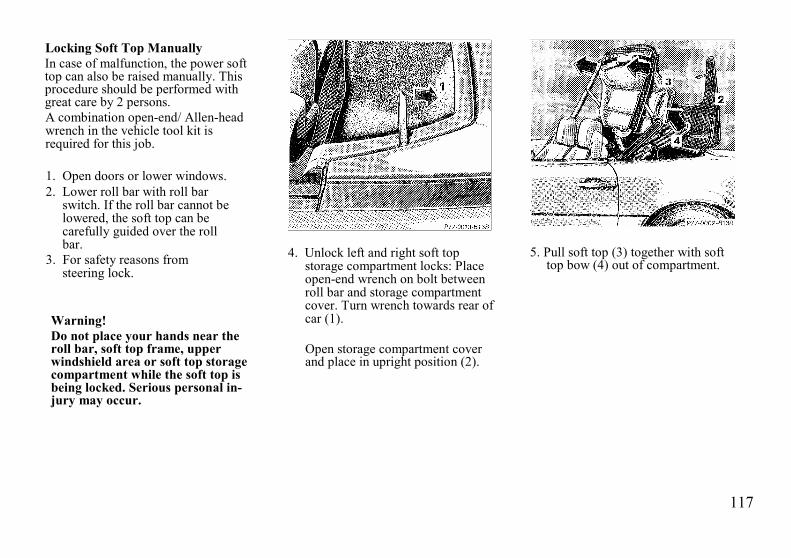
117
Locking Soft Top ManuallyIn case of malfunction, the power softtop can also be raised manually. Thisprocedure should be performed withgreat care by 2 persons.A combination open-end/ Allen-headwrench in the vehicle tool kit isrequired for this job.
1. Open doors or lower windows.2. Lower roll bar with roll bar
switch. If the roll bar cannot belowered, the soft top can becarefully guided over the rollbar.
3. For safety reasons fromsteering lock.
Warning!Do not place your hands near theroll bar, soft top frame, upperwindshield area or soft top storagecompartment while the soft top isbeing locked. Serious personal in-jury may occur.
4. Unlock left and right soft topstorage compartment locks: Placeopen-end wrench on bolt betweenroll bar and storage compartmentcover. Turn wrench towards rear ofcar (1).
Open storage compartment coverand place in upright position (2).
5. Pull soft top (3) together with softtop bow (4) out of compartment.
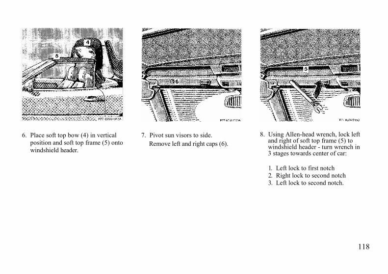
118
6. Place soft top bow (4) in verticalposition and soft top frame (5) ontowindshield header.
7. Pivot sun visors to side.Remove left and right caps (6).
8. Using Allen-head wrench, lock leftand right of soft top frame (5) towindshield header - turn wrench in3 stages towards center of car:
1. Left lock to first notch2. Right lock to second notch3. Left lock to second notch.

119
9. Close storage compartment cover(2).Lock left and right storagecompartment locks: Place open-end wrench on bolt between rollbar and storage compartmentcover. Turn wrench towards frontof car (7).
10. Fold soft top bow (4) down andguide lock pins into locks.
11. Open left and right access covers(8) in trunk by pushing up andremoving.
12. Place open-end wrench on levermarked in red.Press soft top bow (4) down andlock with open-end wrench in 3stages.1. Left lock to first notch2. Flight lock to second notch3. Left lock to second notch.Press the open-end wrenchdown (9) only until the lockaudibly engages.
Have the power soft top chocked atyour authorized MERCEDES-BENZdealer as soon as possible.

120
Locking Hardtop ManuallyIn case of malfunction, the hardtopcan also be locked manually.A combination open-end/Allen-headwrench in the vehicle tool kit isrequired for this job.
1. Open left and right accesscovers (1) in the trunk bypushing up and removing.
2. Place open-end wrench on levermarked in red.
Push the hard top down (2) andusing the open end wrench, lock thehard top in the following sequence:
1. Left lock to first notch2. Right lock to second notch3. Left lock to second notch
Press the open-end wrench down(3) only until the lock audiblyengages.
3. Pivot sun visors to side.Remove left and right caps (4).
Warning!Do not place your hands betweenthe hardtop and the body while thehardtop is being locked. Seriouspersonal injury may occur.

121
4. Using Allen-head wrench, lock leftfront and right front of hardtop towindshield header -turn wrench in 3stages towards center of car:1. Left lock to first notch2. Right lock to second notch3. Left lock to second notch.
Have the hardtop checked at yourauthorized MERCEDES-BENZ dealeras soon as possible.
AshtrayRemoval:Slide open cover, push the sliding knob(1) to the left to eject the insert (2).Installation:Install insert into ashtray frame andpush down to engage.
Manual Release of Fuel Filler Flap
In case of malfunction, the fuel fillerflap can be opened manually. Pull themanual release knob (1) behind theright trunk panel while simultaneouslyopening the fuel filler flap.
Ski Rack
Use only our approved ski rack to avoiddamage to the vehicle. Followmanufacturer's installation instructions.
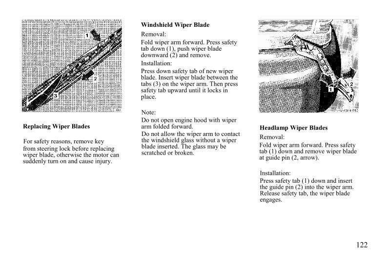
122
Replacing Wiper Blades
For safety reasons, remove keyfrom steering lock before replacingwiper blade, otherwise the motor cansuddenly turn on and cause injury.
Windshield Wiper BladeRemoval:Fold wiper arm forward. Press safetytab down (1), push wiper bladedownward (2) and remove.Installation:Press down safety tab of new wiperblade. Insert wiper blade between thetabs (3) on the wiper arm. Then presssafety tab upward until it locks inplace.
Note:Do not open engine hood with wiperarm folded forward.Do not allow the wiper arm to contactthe windshield glass without a wiperblade inserted. The glass may bescratched or broken.
Headlamp Wiper BladesRemoval:Fold wiper arm forward. Press safetytab (1) down and remove wiper bladeat guide pin (2, arrow).
Installation:Press safety tab (1) down and insertthe guide pin (2) into the wiper arm.Release safety tab, the wiper bladeengages.
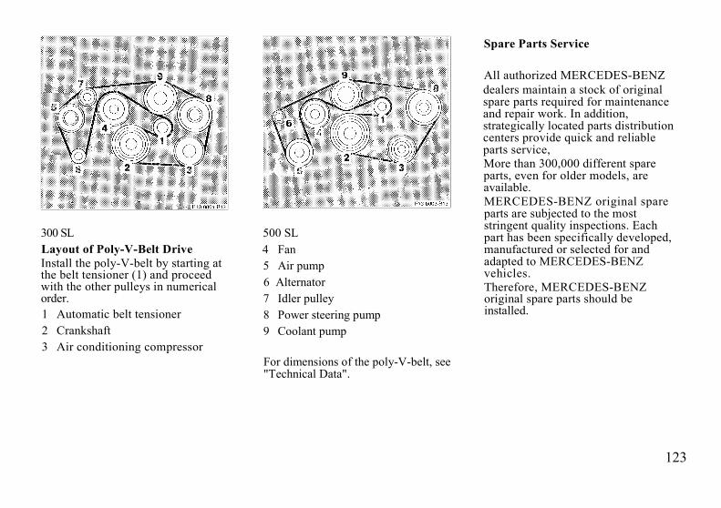
123
300 SLLayout of Poly-V-Belt DriveInstall the poly-V-belt by starting atthe belt tensioner (1) and proceedwith the other pulleys in numericalorder.1 Automatic belt tensioner2 Crankshaft3 Air conditioning compressor
500 SL4 Fan5 Air pump6 Alternator7 Idler pulley8 Power steering pump9 Coolant pump
For dimensions of the poly-V-belt, see"Technical Data".
Spare Parts Service
All authorized MERCEDES-BENZdealers maintain a stock of originalspare parts required for maintenanceand repair work. In addition,strategically located parts distributioncenters provide quick and reliableparts service,More than 300,000 different spareparts, even for older models, areavailable.MERCEDES-BENZ original spareparts are subjected to the moststringent quality inspections. Eachpart has been specifically developed,manufactured or selected for andadapted to MERCEDES-BENZvehicles.Therefore, MERCEDES-BENZoriginal spare parts should beinstalled.

124

125
Technical Data

126
Identification Plates
When ordering spare parts,please specify vehicle identification and engine numbers.
1 Certification Tag(left door pillar)
2 Identification Tag(left window post)
3 Vehicle Identification No.4 Engine No.
(300 SI. right front)5 Body No. and Paint No.6 Emission Control Tag7 Information Tag California version
Vacuum line routing for emissioncontrol system

127
Location of labels1 Bumper front/rear2 Engine hood3 Trunk lid4 All fenders5 All doorsEngine*:on engine block:300 SL, rear500 SL, left rearTransmission*:on transmission, left front* not shown in illustration
Theft PreventionThis vehicle complies with the FederalMotor Vehicle Theft Prevention Standard(49 CFR Part 541). Engine, transmissionand certain body parts (see illustration) arelabeled at factory, the labels show theVIN-number of this vehicle.
Spare parts are similarly labeled atfactory in a different location. Thelabels show the letter R (forreplacement) instead of the VIN-number.
Note:Do not remove these labels. These labelsare intended for parts identification incase of theft. When replacing partssubject to labeling, please make sure thatthe parts you receive are labeled properly.This is especially important when work isperformed outside of the United States.
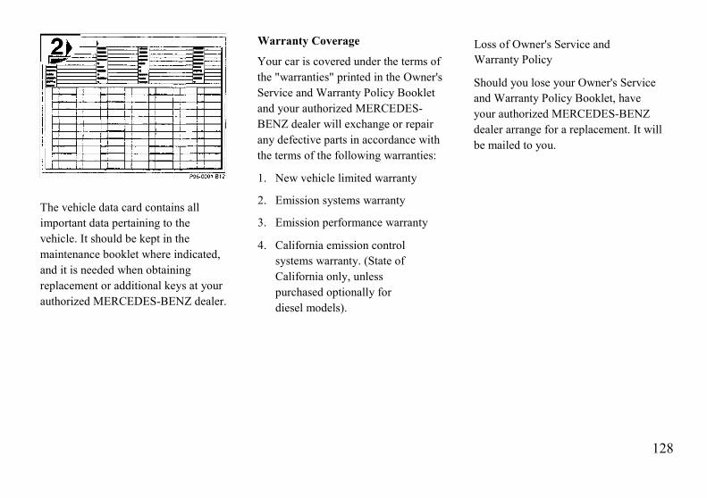
128
Loss of Owner's Service andWarranty Policy
Should you lose your Owner's Serviceand Warranty Policy Booklet, haveyour authorized MERCEDES-BENZdealer arrange for a replacement. It willbe mailed to you.
The vehicle data card contains allimportant data pertaining to thevehicle. It should be kept in themaintenance booklet where indicated,and it is needed when obtainingreplacement or additional keys at yourauthorized MERCEDES-BENZ dealer.
Warranty Coverage
Your car is covered under the terms ofthe "warranties" printed in the Owner'sService and Warranty Policy Bookletand your authorized MERCEDES-BENZ dealer will exchange or repairany defective parts in accordance withthe terms of the following warranties:
1. New vehicle limited warranty
2. Emission systems warranty
3. Emission performance warranty
4. California emission controlsystems warranty. (State ofCalifornia only, unlesspurchased optionally fordiesel models).
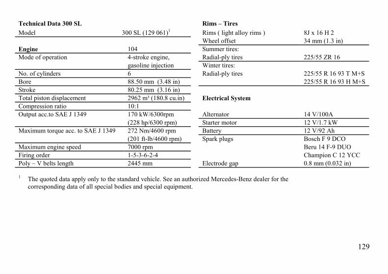
129
Technical Data 300 SL Rims – TiresModel 300 SL (129 061)1 Rims ( light alloy rims ) 8J x 16 H 2
Wheel offset 34 mm (1.3 in)Engine 104 Summer tires:Mode of operation 4-stroke engine, Radial-ply tires 225/55 ZR 16
gasoline injection Winter tires:No. of cylinders 6 Radial-ply tires 225/55 R 16 93 T M+SBore 88.50 mm (3.48 in) 225/55 R 16 93 H M+SStroke 80.25 mm (3.16 in)Total piston displacement 2962 m³ (180.8 cu.in) Electrical SystemCompression ratio 10:1Output acc.to SAE J 1349 170 kW/6300rpm Alternator 14 V/100A
(228 hp/6300 rpm) Starter motor 12 V/1.7 kWMaximum torque acc. to SAE J 1349 272 Nm/4600 rpm Battery 12 V/92 Ah
(201 ft-lb/4600 rpm) Spark plugs Bosch F 9 DCOMaximum engine speed 7000 rpm Beru 14 F-9 DUOFiring order 1-5-3-6-2-4 Champion C 12 YCCPoly – V belts length 2445 mm Electrode gap 0.8 mm (0.032 in)
1 The quoted data apply only to the standard vehicle. See an authorized Mercedes-Benz dealer for thecorresponding data of all special bodies and special equipment.

130
Technical Data 300 SL
Weights See certification tag Main DimensionsHardtop load max. 30 kg ( 66 lb) Overall vehicle length 4470 mm (176.0 in)Trunk load max. 100 kg (220 lb) Overall vehicle width 1812 mm ( 71.3 in)
Overall height:Soft top 1298 mm ( 51.1 in)Hardtop 1288 mm ( 50.7 in)
Wheel base 2515 mm ( 99.0 in)Track, front 1532 mm ( 60.3 in)Track, rear 1521 mm ( 59.9 in)

131
Technical Data 500 SL Rims – TiresModel 500 SL (129 066)1 Rims ( light alloy rims ) 8J x 16 H 2
Wheel offset 34 mm (1.3 in)Engine 119 Summer tires:Mode of operation 4-stroke engine, Radial-ply tires 225/55 ZR 16
gasoline injection Winter tires:No. of cylinders 8 Radial-ply tires 225/55 R 16 93 T M+SBore 96.50 mm (3.80 in) 225/55 R 16 93 H M+SStroke 85.00 mm (3.35 in)Total piston displacement 4973 m³ (305.5 cu.in) Electrical SystemCompression ratio 10:1Output acc.to SAE J 1349 240 kW/5500rpm Alternator 14 V/100A
(322 hp/5500 rpm) Starter motor 12 V/1.7 kWMaximum torque acc. to SAE J 1349 450 Nm/4000 rpm Battery 12 V/92 Ah
(332 ft-lb/4000 rpm) Spark plugs Bosch F 8 DCOMaximum engine speed 6000 rpm Beru 14 F-8 DUOFiring order 1-5-4-8-6-3-7-2 Champion C 10 YCCPoly – V - belts length 2523mm Electrode gap 0.8 mm (0.032 in)
1 The quoted data apply only to the standard vehicle. See an authorized Mercedes-Benz dealer for thecorresponding data of all special bodies and special equipment.

132
Technical Data 500 SL
Weights See certification tag Main DimensionsHardtop load max. 30 kg ( 66 lb) Overall vehicle length 4470 mm (176.0 in)Trunk load max. 100 kg (220 lb) Overall vehicle width 1812 mm ( 71.3 in)
Overall height:Soft top 1298 mm ( 51.1 in)Hardtop 1288 mm ( 50.7 in)
Wheel base 2515 mm ( 99.0 in)Track, front 1532 mm ( 60.3 in)Track, rear 1521 mm ( 59.9 in)
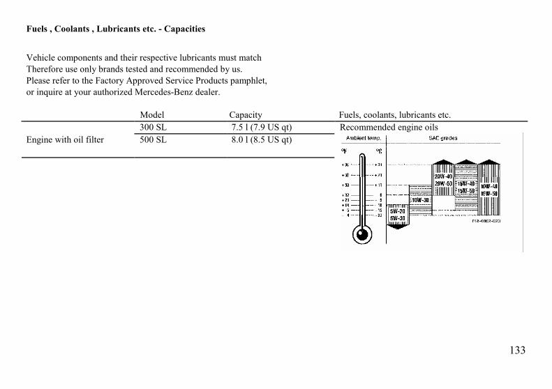
133
Fuels , Coolants , Lubricants etc. - Capacities
Vehicle components and their respective lubricants must matchTherefore use only brands tested and recommended by us.Please refer to the Factory Approved Service Products pamphlet,or inquire at your authorized Mercedes-Benz dealer.
Model Capacity Fuels, coolants, lubricants etc.300 SL 7.5 l (7.9 US qt)
Engine with oil filter 500 SL 8.0 l (8.5 US qt)Recommended engine oils

134
Model Capacity Fuels, coolants, lubricants etc.5-SpeedManual transmission
300 SL 1.6 l (1.7 US qt) MB Manual transmission fluid 1
Automatic transmission300 SL Initial fill: 7.1 l (7.5 US qt)
Fluid change: 6.0 l (6.3 US qt)500 SL Initial fill: 8.6 l (9.1 US qt)
Fluid change: 7.7 l (8.1 US qt)MB Automatic transmission fluid 1
Rear axle 1.3 l (1.4 US qt) Hypoid gear oil SAE 90, SAE 85 W 901
Power steering approx. 1.0 l (1.1 US qt) MB Power steering fluid 1
Level control approx. 2.0 l (2.1 US qt) Hydraulic oil1
Front wheel hubs approx. 60g (2.1 oz) each High temperature roller bearing greaseBattery terminals Bosch special grease (acid proof)Accelerator control linkage Hydraulic fluid 1
Brake system approx. 05 l (0.5 US qt) MB Brake fluid (DOT 4)Brake system Clutch
1 Your authorized MERCEDES-BENZDealer will advise you onrecommended brands.

135
Model Capacity Fuels, coolants, lubricants etc.Windshield washer approx. 5l (5.3 US qt) MB Windshield washerand headlamp concentrate “S” 1
cleaning systemCooling system 300 SL approx. 11.5 l (12.2 US qt) MB Anticorrosion/antifreeze
500 SL approx. 15 l (15.9 US qt)Fuel tank approx. 80 l (21.1 US gal) Premium unleaded gasoline: Postedincluding a reserve of approx. 10 l (2.6 US gal) Octane 91 (Average of 96 RON/86 MON)
1 Use MB Windshield Washer Concentrate “S” and water for temperatures above freezing or MB Windshield WasherConcentrate “S” and commercially available premixed windshield washer solvent/antifreeze for temperatures belowfreezing. Follow suggested mixing ratios, see page 51
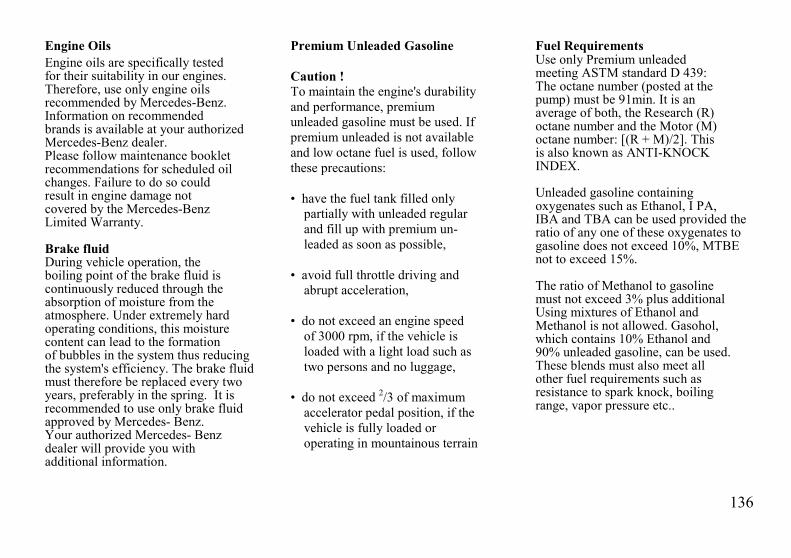
136
Engine OilsEngine oils are specifically testedfor their suitability in our engines.Therefore, use only engine oilsrecommended by Mercedes-Benz.Information on recommendedbrands is available at your authorizedMercedes-Benz dealer.Please follow maintenance bookletrecommendations for scheduled oilchanges. Failure to do so couldresult in engine damage notcovered by the Mercedes-BenzLimited Warranty.
Brake fluidDuring vehicle operation, theboiling point of the brake fluid iscontinuously reduced through theabsorption of moisture from theatmosphere. Under extremely hardoperating conditions, this moisturecontent can lead to the formationof bubbles in the system thus reducingthe system's efficiency. The brake fluidmust therefore be replaced every twoyears, preferably in the spring. It isrecommended to use only brake fluidapproved by Mercedes- Benz.Your authorized Mercedes- Benzdealer will provide you withadditional information.
Premium Unleaded Gasoline
Caution !To maintain the engine's durabilityand performance, premiumunleaded gasoline must be used. Ifpremium unleaded is not availableand low octane fuel is used, followthese precautions:
• have the fuel tank filled onlypartially with unleaded regularand fill up with premium un-leaded as soon as possible,
• avoid full throttle driving andabrupt acceleration,
• do not exceed an engine speedof 3000 rpm, if the vehicle isloaded with a light load such astwo persons and no luggage,
• do not exceed 2/3 of maximumaccelerator pedal position, if thevehicle is fully loaded oroperating in mountainous terrain
Fuel RequirementsUse only Premium unleadedmeeting ASTM standard D 439:The octane number (posted at thepump) must be 91min. It is anaverage of both, the Research (R)octane number and the Motor (M)octane number: [(R + M)/2]. Thisis also known as ANTI-KNOCKINDEX.
Unleaded gasoline containingoxygenates such as Ethanol, I PA,IBA and TBA can be used provided theratio of any one of these oxygenates togasoline does not exceed 10%, MTBEnot to exceed 15%.
The ratio of Methanol to gasolinemust not exceed 3% plus additionalUsing mixtures of Ethanol andMethanol is not allowed. Gasohol,which contains 10% Ethanol and90% unleaded gasoline, can be used.These blends must also meet allother fuel requirements such asresistance to spark knock, boilingrange, vapor pressure etc..
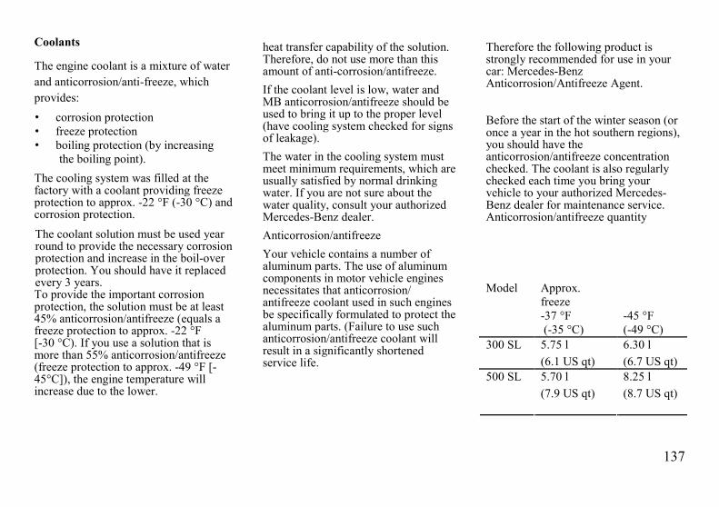
137
Coolants Therefore the following product isstrongly recommended for use in yourcar: Mercedes-BenzAnticorrosion/Antifreeze Agent.
Before the start of the winter season (oronce a year in the hot southern regions),you should have theanticorrosion/antifreeze concentrationchecked. The coolant is also regularlychecked each time you bring yourvehicle to your authorized Mercedes-Benz dealer for maintenance service.Anticorrosion/antifreeze quantity
Model Approx.freeze-37 °F(-35 °C)
-45 °F(-49 °C)
300 SL 5.75 l 6.30 l(6.1 US qt) (6.7 US qt)
500 SL 5.70 l 8.25 l
The engine coolant is a mixture of waterand anticorrosion/anti-freeze, whichprovides:• corrosion protection• freeze protection• boiling protection (by increasing
the boiling point).The cooling system was filled at thefactory with a coolant providing freezeprotection to approx. -22 °F (-30 °C) andcorrosion protection.
The coolant solution must be used yearround to provide the necessary corrosionprotection and increase in the boil-overprotection. You should have it replacedevery 3 years.To provide the important corrosionprotection, the solution must be at least45% anticorrosion/antifreeze (equals afreeze protection to approx. -22 °F[-30 °C). If you use a solution that ismore than 55% anticorrosion/antifreeze(freeze protection to approx. -49 °F [-45°C]), the engine temperature willincrease due to the lower.
heat transfer capability of the solution.Therefore, do not use more than thisamount of anti-corrosion/antifreeze.If the coolant level is low, water andMB anticorrosion/antifreeze should beused to bring it up to the proper level(have cooling system checked for signsof leakage).The water in the cooling system mustmeet minimum requirements, which areusually satisfied by normal drinkingwater. If you are not sure about thewater quality, consult your authorizedMercedes-Benz dealer.Anticorrosion/antifreezeYour vehicle contains a number ofaluminum parts. The use of aluminumcomponents in motor vehicle enginesnecessitates that anticorrosion/antifreeze coolant used in such enginesbe specifically formulated to protect thealuminum parts. (Failure to use suchanticorrosion/antifreeze coolant willresult in a significantly shortenedservice life.
(7.9 US qt) (8.7 US qt)
138
Consumer InformationThis has been prepared as required of allmanufacturers of passenger cars underTitle 49, Code of U.S. FederalRegulations, Part 575 pursuant to the"National Traffic and Motor VehicleSafety Act of 1966".
Uniform Tire Quality GradingRefer to the tire sidewall for the specifictire grades for the tires with which thisvehicle is equipped.All passenger car tires must conform tofederal safety requirements in addition tothese grades.TreadwearThe treadwear grade is a comparativerating based on the wear rate of the tirewhen tested under controlled conditionson a specified government test course.For example, a tire graded 150 wouldwear one and one-half (11/2) times aswell on the government course as a tiregraded 100. The relative performance oftires "depends upon the actual conditionsof their use, however, and may depart
significantly from the norm due tovariations in driving habits, servicepractices and differences in roadcharacteristics and climate.
Traction "A", "B", "C"The traction grades, from highest tolowest, are "A", "B" and "C" and theyrepresent the tire's ability to stop on wetpavement as measured under controlledconditions on specified government testsurfaces of asphalt and concrete. A tiremarked "C" may have poor tractionperformance.
Warning!
The traction grade assigned to thistire is based on braking (straightahead) traction tests and does notinclude cornering (turning) traction.
Temperature "A", "B", "C"The temperature grades are "A" (thehighest). "B" and "C", representing thetire's resistance to the generation of heatand its ability .to dissipate heat when
tested under controlled conditions on aspecified indoor laboratory test wheel.Sustained high temperature can causethe material of the tire to degenerateand reduce tire life, and excessivetemperature can lead to sudden tire fail-ure. The grade "C" corresponds to alevel of performance which allpassenger car tires must meet under theFederal Motor Vehicle Safety StandardNo. 109 Grades "B" and "A" representhigher levels of performance on thelaboratory test wheel than the minimumrequired by law.
Warning!
The temperature grade for this tireis established for a tire that isproperly inflated and notoverloaded. Excessive speed,underinflation, or excessive loading,either separately or in combination,can cause excessive heat build upand possible tire failure.

139
Index
140
Airbag 43Alarm system 32Alloy wheels 114Antenna 71, 114Anticorrosion/antifreeze 137Arm rest 38Ashtray 121Automatic climate control 22Automatic transmission 76Fluid level check 97
Battery 105Body no. 126Brake fluid 136Brake pad wear indicator lamp 88Brake, parking 74Brakes 16Brakes, ABS 89Brake warning lamp 88Break-in period 8
Capacities 133Catalytic converter 14Central locking system 29Certification tag 126Charge indicator lamp 83Cleaning and care of the vehicle 112Clock, setting 55Combination switch 50Compartments 57, 58
Console storage 58Door pockets 58Eyeglasses 57Storage 57Rear storage 58
Consumer information 138Coolant level check 95Coolants 135, 137Coolant temperature gauge 85Cruise control 81
Door pockets 58Doors 29Driver checks 144Driving instructions 16
Emergency tensioningretractors (ETR) 42Emission control 90Emission control tag 126Engine no. 126Engine oil and filter change 20Engine oil consumption 84Engine oil level check 96Engine oils 136Engine starting and turning off 15Eyeglasses compartment 57Exterior lamp switch 52Exterior light failure indicator lamp 87
First aid kit 98Fuel filler flap 121Fuel consumption gauge 84Fuel requirements 136Fuel reserve warning lamp 85Fuels, coolants, lubricants, etc. 133Fuses 106
Gauges 12, 83, 84, 85Coolant temperature 85Fuel 85Fuel consumption 84Oil pressure 83

141
Hardtop 62, 120Locking manually 120Headlamps 50, 107Headlamp washer 50Head restraint 33Heated seats 37Hood 94
Identification plates 126Indicator lamps 12, 13, 83, 84,
85, 86, 87, 88, 90Backrest lock 87Brake pad wear 88Brake warning 88Charging system 83Check engine 90Exterior lamp failure 87Fuel reserve 85Low coolant 86Low engine oil 84Low washer fluid 86Roll bar 86Symbols 13
Infrared remote control 27, 116Testing 116Changing batteries 116
Instruments and controls 10Instrument cluster 12
Jack 99Jump starting 109
Keys 26
Lamps, exterior 52, 107, 108, 109Headlamps 107License plate lamps 109Switch 52Taillamps 108
Lamps, interior56Reading 56Entrance 56Exit 56
Lighter 57Literature 143Lubricants 133
Maintenance 4, 20Manual transmission 75
Oil pressure gauge 83On-board diagnostic system(California models only) 90Orthopedic seat 36Outside temperature indicator 85
Paintwork no. 126Parking 18Parking brake 74Premium unleaded gasoline135, 136
Rear view mirrors 53, 54Rear window defroster 59Restraint systems,
infants and children 47Roadside assistance 4Roll bar 60
142
Seat belts 39, 113Warning system 39
Seats 33, 34, 35, 36Service literature 143Shifting 75, 76
Automatic transmission 76Manual transmission 75Recommended shift points for manualtransmission 75
Ski rack 121Snow chains 91Soft top 66, 115, 117
Locking manually 117Spare parts 123Spare wheel 98Spark plugs 106Starting and shifting gears 74Starting and turning off engine 15Steering column, adjusting 38Steering lock 48Storage compartment 57Sun visors 55Supplemental restraint system (SRS) 39, 42
Technical data 129, 131Theft prevention 127Tire pressure 104Tires 17,99, 138Towing 111Traveling abroad 91Trunk lamp 98Trunk jock 30Turn signals 50
Upholstery, cleaning 114
Vanity mirror 55V-belt 123, 129, 131Vehicle data card 128Vehicle identification no. 126Vehicle tools 99
Warranty 4, 128Wheels 99Wheels, changing 101Windscreen 69Windows 60Windshield/headlamp washer
system 51, 86, 135Windshield wiper 51, 122Winter driving 19, 91Wiper blades 113, 122
Replacing 122
143
Service LiteratureYour authorized MERCEDES-BENZ dealer has trainedtechnicians and original MERCEDES-BENZ parts to service yourvehicle properly. For expert advice and quality service, see yourauthorized MERCEDES-BENZ dealer.Customers who are interested in ordering service literature fortheir vehicles are advised to contact MERCEDES-BENZdistributors in the U.S. or Canada at the following addresses,respectivelyfor U.S.A.: Mercedes-Benz of North America Inc.
One Mercedes Drive P. O. Box 350Montvale, New Jersey 07645Att: Service and Parts LiteratureTel: (201) 573-0600
for Canada: Mercedes-Benz Canada Inc. 849 EglintonAve., East Toronto, Ont., Canada M4G 2L5Att: Technical PublicationsTel: 416-425-3550 Telex: 065-24232
The above companies will be happy to handle any such requestsfrom customers.We consider this to be the best way to obtain accurate informationfor your vehicle
Warning!To help avoid personal injury, be extremely carefulwhen performing any maintenance work or repairs.Improper or incomplete service may damage the vehicleor its equipment, which may in turn result in personalinjury.If you have any question about carrying out someservice, turn to the advice of an authorizedMERCEDES-BENZ dealer.
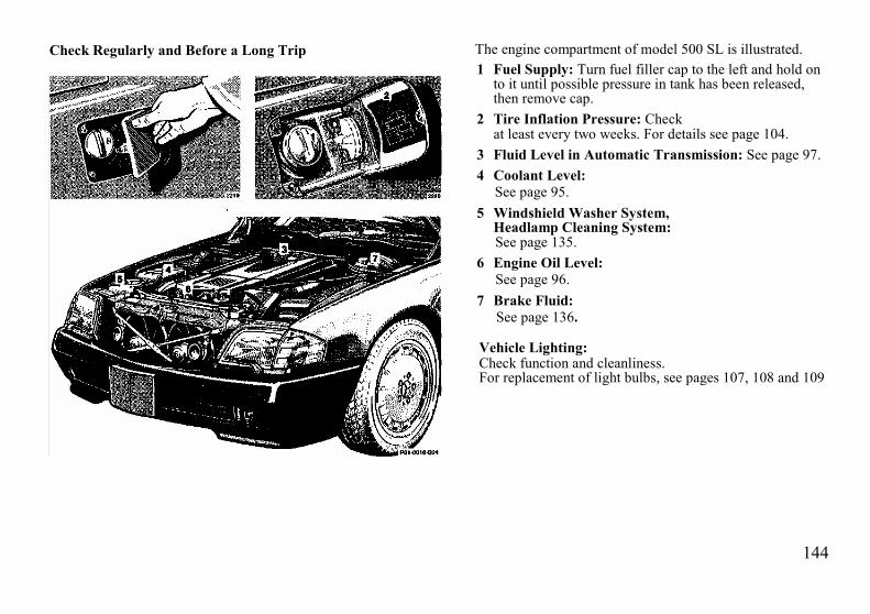
144
Check Regularly and Before a Long Trip The engine compartment of model 500 SL is illustrated.1 Fuel Supply: Turn fuel filler cap to the left and hold on
to it until possible pressure in tank has been released,then remove cap.
2 Tire Inflation Pressure: Checkat least every two weeks. For details see page 104.
3 Fluid Level in Automatic Transmission: See page 97.4 Coolant Level:
See page 95.5 Windshield Washer System,
Headlamp Cleaning System:See page 135.
6 Engine Oil Level:See page 96.
7 Brake Fluid:See page 136.
Vehicle Lighting:Check function and cleanliness.For replacement of light bulbs, see pages 107, 108 and 109
145
What You Should Know at the Gas Station
• Fuel:Use premium unleaded gasoline: Posted Octane Index 91(Average of 96 RON/86 MON).Fuel tank capacity approx. 80 l (21.1 US gal). This includesapprox. 10 l (2.6 US gal) reserve.Only fill fuel tank until the filler nozzle unit cuts out - do notoverfill.
Warning!Gasoline vapor is highly flammable. It burns violently andcan cause serious injury. Whenever you are aroundgasoline, extinguish all smoking materials. Never getsparks, flame or smoking materials near gasoline!
• Engine Oil:Engine oil level check, see page 96.Quantity differential between upper and lower dipstickmarking level: 2.0 l (2.1 US qt).Recommended engine oils, see page 133.
• Automatic Transmission:MB Automatic transmission fluid.For level checks and replenishment, refer to page 97.
• Coolant:For normal replenishing, use water (potable waterquality).For further information (e.g. anticorrosion/antifreeze), refer to page 137.
• Spark Plugs:Approved spark plugs, refer to "Technical Data".
• Bulbs:High and low beams: Halogen type 9004,fog lamps: Halogen type H1 (55 W),tail, parking and standing lamps21/4 W/35/1.2 cp,driver's side:tail, parking, standing and rear foglamp 21/4 W/35/1.2 cp,turn signal, standing, side marker and parkinglamps, front 21/5 W/32/3 cp,turn signal lamps, rear 21 W/32 cp,stop lamps 21 W/32 cp,license plate lamps 5 W.
• Tire Pressure:For tire pressure, refer to tire pressure inside thefuel filler flap.