Embed Size (px)
Citation preview
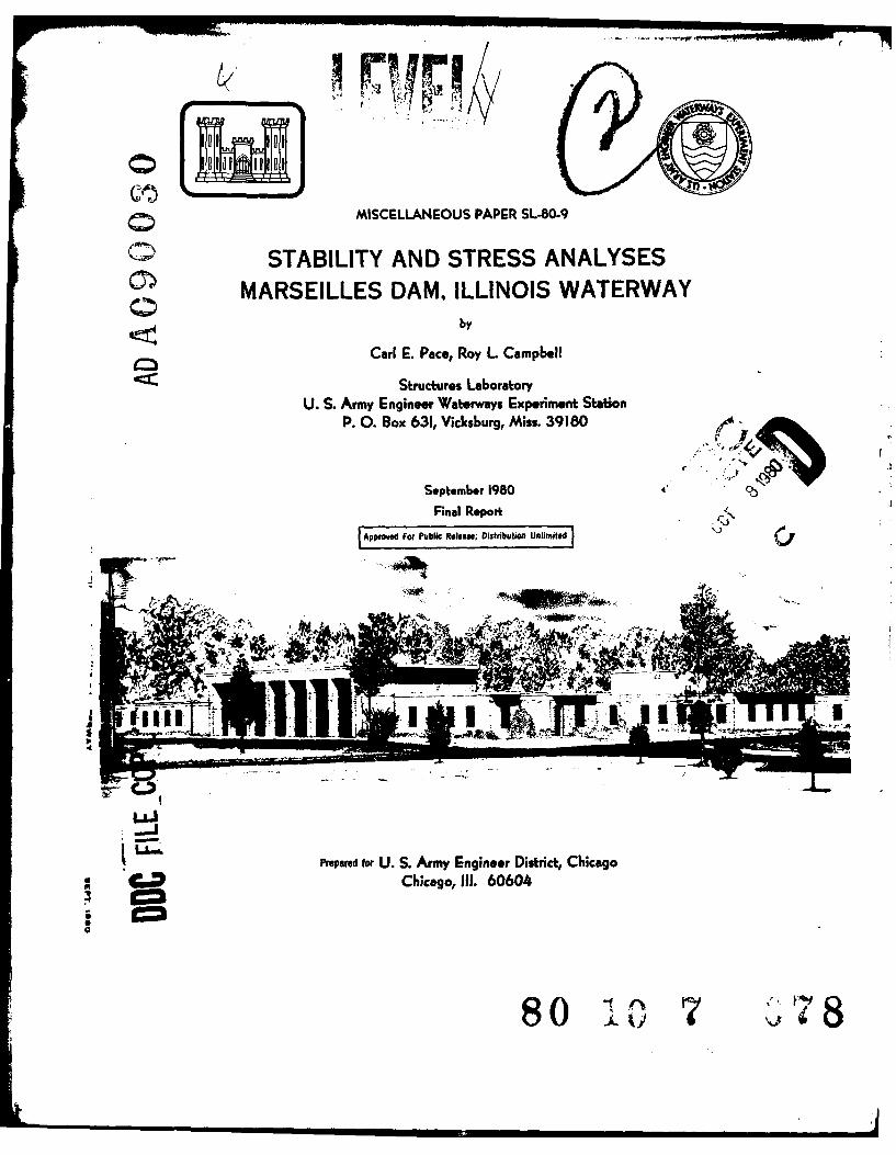
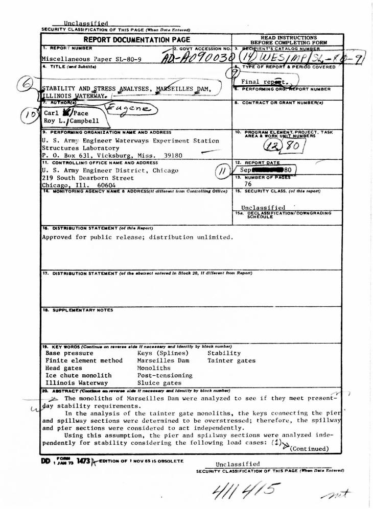
MISCELLANEOUS PAPER SL-80-9
STABILITY AND STRESS ANALYSESMARSEILLES DAM, ILLINOIS WATERWAY
by
Carl E. Pace, Roy L. Campbell
Structures LaboratoryU. S. Army Engineer Waterways Experiment Station
P. 0. Box 631, Vicksburg, Miss. 39180
Septembelr 1980 *C
Final Re9port
Approved For Public Release; Distribution Unlimited
.-4
Prepared for U. S. Army Engineer District, ChicagoChicago, Ill. 60604
so
0
H
Destroy this report when no longer needed. Do not returnit to the originator.
The findings in this report are not to be construed as an official
Department of the Army position unless so designatedby other authorized documents.
Ii4
Unclassified SECURITY CLASSII'ICATION OF THIS PAGE (When D11t• Entered)
REPORT DOCUMENTATION PAGE READ INSTRUCTIONS BEFORE COMPLETING FORM
I'· AEPOR T NUMBER
A1J~#~A9-tl~3°~ 3. ~lENT'S CAT~LOG IWWBEA -
~iscellaneous Paper SL-80-9 D (If) LUE5; IJJf/St... - K_~. t;_z 4. TITLE (_,d S..l>lll/e)
( ~ TYP£ o• R<P:f. P£mOo OOV<..O
~ ~TABILITY AND.J_TRESS JN~S, -~ES~~, Final rep•t. ) '1. PERFORMING OA~PORT NUMBER
[ILLINOIS JiATERWAY .. 1 . -I'· "UTHO"f•L ~ ~ .. CONTRACT OR GRANT NUMBER(•)
(!~ Carl W/Pace '\ "'-i "-"e.. Roy L · /Campbell ~
t. PERFOIWING ORGANIZATION NAME AND ADDRESS 10. :=~~~A=OERLE~~·~U~oi:~i · TASK
u. s. Army Engi neer Wa t en.,ays Exper i ment St a tion """ 7o I Structures Laboratory
~ -
P. 0. Box 631, Vicksburg, Miss . 39180 11. CONTROLLING OFFICE NAME AND ADDRESS
® 12. REPORT OAT&._ r
u. s. Army Engineer Dist r ict , Chicago I Sep 80 ) 219 South Dearborn Street 13. NUMBER OF PIO~O:.:> -
Chicago , Ill. 60604 76 14. MONITORING AGENCY NAME a AOORESS(/1 dltter""t from Conttolllnl Oltl ce) 15. SECURITY CLASS. (ollhle r_,.,rt)
Unclas s ified 15• . ~~~fC~~ItiCATION/DOWNGRADING
II. OISTAIBUTION STATEMENT (of IIIIa Report)
Approved for public r e l ease; distribut ion unlimited.
1'7. DISTRIBUTION STATEMENT (of lila Nallac t ontered In Blocl< 20, II dlllerent from Report)
11. SUPPLEMENTARY NOTES
lt. KEY WOROS (Continue on ,...., •• aide II neceaaary .,d Identity l>y l>locl< number)
Base pressure Keys (Splines ) Stability Finite element method Marseilles Dam Tainter gates Head gates Monoliths Ice chute monolith Post-tensioni ng Illinois Waterway Sluice ga t es
10. A-Tl'IAC:T (C'__,.-,._ • l tlt II ..--eery - ldenJity,. block n-1>«) ,...-y )
-- - ..,;b. The monoliths of Ma r seilles Dam we re analyzed t o sec if t hey meet present-
<A.. )ay s tabi lity r equi r ements . the keys connecting the pier
. ln the analysis of t he tain ter gate monoli t hs ,
and spillway sections were de t ermined to be overs tressed; t herefo re, t he spillway and pier sections were consi dered to act i ndependen tly.
Using this assumption, the pie r and spi~lway sections wer e ana lyzed inde-pendently for stability considering the followi ng load cases: ( 1)~
(Continued)
DD I ~=-71 1473 ~TIOM OF I NOV 8S IS OltSOl.E TE Unclassified SECURITY CLASSIFICATION 0,. T HIS PAG£ ( ..,._,Date Entered}

UnclassifiedSECURITY CLASSIFICATION OF THIS PAGE( -IMP DMta Bnt..4)
20. ABSTRACT (Continued)
Normal operation;Normal operation with ice,
Normal operation with earthquake, -
Flood condition.
The results showed that the spillway sections were adequate in stability,
and the pier sections were inadequate against overturning. To correct the in-
adequacy of the pier sections, it was recommended that each pier section be
posttensioned using a 602-kip force. The pier sections were reanalyzed to in-
clude the recommended posttensioning and were determined to be adequate in
stability. The resulting stresses in the structure, foundation, and grouted
anchors were computed and determined to be within allowables.
A previous stability investigation by the U. S. Army Engineer District,
Chicago, concluded that the stability of the ice chute monoliths was adequate.
This paper concurs with that conclusion.
I.Unclassified
SECURITY CLASSIFICATION OF THIS PAOE(ft.., Dof KnjereJ)
J III
PREFACE
The stability analysis of Marseilles Dam was performed in 1979
for the U. S. Army Engineer District, Chicago, by the Structures Labora-
tory (SL) of the U. S. Army Engineer Waterways Experiment Station (WES).
The contract was monitored by Messrs. Ignas Juzenas and
George Sanborn. Their interest and help was greatly appreciated.
The study was performed under the direction of Messrs. B. Mather,
W. J. Flathau, and J. M. Scanlon, SL. The structural analysis was per-
formed by Dr. C. E. Pace, Messrs. R. L. Campbell and E. F. O'Neil, and
SP5 John Z. Oak. The material properties were obtained by Mr. R. L. Stowe
and WES Soils and Pavements Laboratory. The report was prepared by
Dr. Pace and Mr. Campbell.
The Commanders and Directors of WES during the conduct of this
test program and the preparation and publication of this report were
COL John L. Cannon, CE, and COL Nelson P. Conover, CE. Mr. F. R. Brown
was Technical Director.
Al
&
I- ___
CONTENTS
Page
PREFACE......................... .. .. ......
CONVERSION FACTORS, INCH-POUND TO METRIC (SI) UNITS OFMEASUREMENT. .. ........................... 3
PART 1: INTRODUCTION. .. ...................... 4
Background......................................................4Stability Analysis*.. ....................... 4Stress Analysis. .. ........................ 6Objective. .. ........................... 7
PART II: STABILITY ANALYSIS .. .. ................. 8
Tainter Gate Monolith. .. ..................... 8Ice Chute Monolith. .. .................. .... 12
PART III: STRESS ANALYSIS. .. .................... 13
Pier. .. ................. ............ 13Pier Foundation .. .................. ...... 14
REFERENCES. .. ................. .......... 17
APPENDIX A: STABILITY AND STRESS ANALYSIS DATA
2
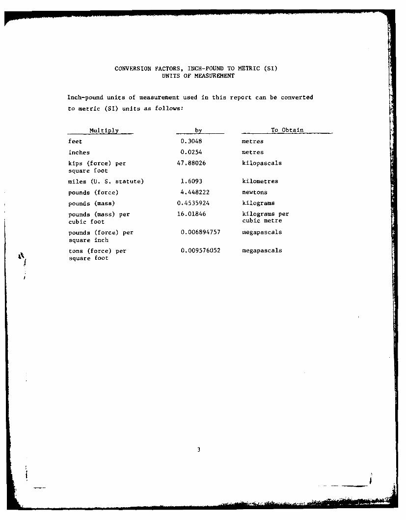
CONVERSION FACTORS, INCH-POUND TO METRIC (SI)UNITS OF MEASUREMENT
Inch-pound units of measurement used in this report can be converted
to metric (SI) units as follows:
Multiply by To Obtain
feet 0.3048 metres
inches 0.0254 metres
kips (force) per 47.88026 kilopascals
square foot
miles (U. S. statute) 1.6093 kilometres
pounds (force) 4.448222 newtons
pounds (mass) 0.4535924 kilograms
pounds (mass) per 16.01846 kilograms per
cubic foot cubic metre
pounds (force) per 0.006894757 megapascalssquare inch
tons (force) per 0.009576052 megapascalssquare foot
3
.,'l
STABILITY AND STRESS ANALYSES, MARSEILLES DAM,
ILLINOIS WATERWAY
PART I: INTRODUCTION
Background
1. The Marseilles Dam is on the Illinois Waterway near Marseilles,
Ill., which is about 60 miles* southeast of Chicago. Previously
published reports by the U. S. Army Engineer District, Chicago (1973a,
b, and c), present the overall view and sections of the dam. The mate-
rial properties of the concrete and foundation are described by Stowe
(1979).
2. Even though the Marseilles structures have been in service
for a long time, it is important that they be examined to view their
present condition in relation to present-day criteria to assure contin-
ued structural adequacy. If the design of the structure is judged to be Vinadequate or if the deterioration of the structure causes inadequacies,
feasible modifications must be made.
Stability Analysis
3. One of the main considerations for structural adequacy of a
dam is the stability of its various monoliths when subjected to possible
loading conditions. Stability studies involve the analyses of selected
monoliths to determine if they have adequate resistance against overturn-
ing, sliding, and base pressures.
Overturning
4. The adequacy of the structure to resist overturning can be
judged by the location of the resultant with respect to the base of the
A table of factors for converting inch-pound units of measurement tometric (SI) units is presented on page 3.
4
section where stability is being considered within the dam, at the base-
foundation interface, or at a plane or combination of planes below the
base. In general, the gravity sections where stability against -verturn-
ing is being considered are required to have the resultant of applied
loads fall within the kern of the base of the section being analyzed.
However, for operating conditions with earthquake, the resultant may
fall outside of the kern, but within the base, as long as allowable
foundation stresses are not exceeded.
5. The percent effective base (percent of the base which is in
compression) is a good way of representing where the resultant falls in
a rectangular based section. It is a good guide for representing over-
turning resistance for any shape base. An example for a rectangular
base follc-s:
Percent Effective Base Resultant Location Within Base
100 Within middle third or in kern area75 At a quarter point of base50 At a sixth point of base
Sliding
6. Sliding resistance of a monolith is calculated by choosing a
trial failure plane or combination of planes and calculating the resis-
tance along that path. The resistance may be composed of several types.
The sliding resistance due to friction and cohesion of the surface be-
tween the monolith and its foundation is calculated by the shear-friction
formula given in ETL 1110-2-184 (Department of the Army, Office, Chief
of Engineers, 1974). However, the formula in this ETL is inadequate for
evaluating structural sliding on inclined planes. The sliding resistance
due to all or any part of the failure plane extending through either the
concrete monolith or the foundation is calculated from the shearing
strength of the material acting over the length in which shearing occurs.
7. In general, a shear-friction safety factor of 4 is required
for all conditions of loading where earthquake is not considered and is
2-2/3 for loading conditions considering earthquake. In discussions
5
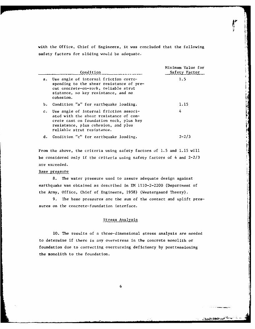
with the Office, Chief of Engineers, it was concluded that the following
safety factors for sliding would be adequate.
Minimum Value forCondition Safety Factor
a. Use angle of internal friction corre- 1.5sponding to the shear resistance of pre-cut concrete-on-rock, reliable strutsistance, no key resistance, and nocohesion.
b. Condition "a" for earthquake loading. 1.15
c. Use angle of internal friction associ- 4ated with the shear resistance of con-crete cast on foundation rock, plus keyresistance, plus cohesion, and plusreliable strut resistance.
d. Condition "c" for earthquake loading. 2-2/3
From the above, the criteria using safety factors of 1.5 and 1.15 will
be considered only if the criteria using safety factors of 4 and 2-2/3
are exceeded.
Base pressure
8. The water pressure used to assure adequate design against
earthquake was obtained as described in EM 1110-2-2200 (Department of
the Army, Office, Chief of Engineers, 1958) (Westergaard Theory).
9. The base pressures are the sum of the contact and uplift pres-
sures on the concrete-foundation interface.
Stress Analysis
10. The results of a three-dimensional stress analysis are needed
to determine if there is any overstress in the concrete monolith or
foundation due to correcting overturning deficiency by posttensioning
the monolith to the foundation.
6

Objective
11. The objective of this study was to analyze the monoliths of
the Marseilles Dam to see if they meet present-day stability require-
ments. If present-day criteria were not met, corrective measures were
to be recommended.
i7
1 !°7
-.
PART III: STABII.ITY ANALYSIS
Tainter Gate Monolith
Stress in keys betweenpier and spillway
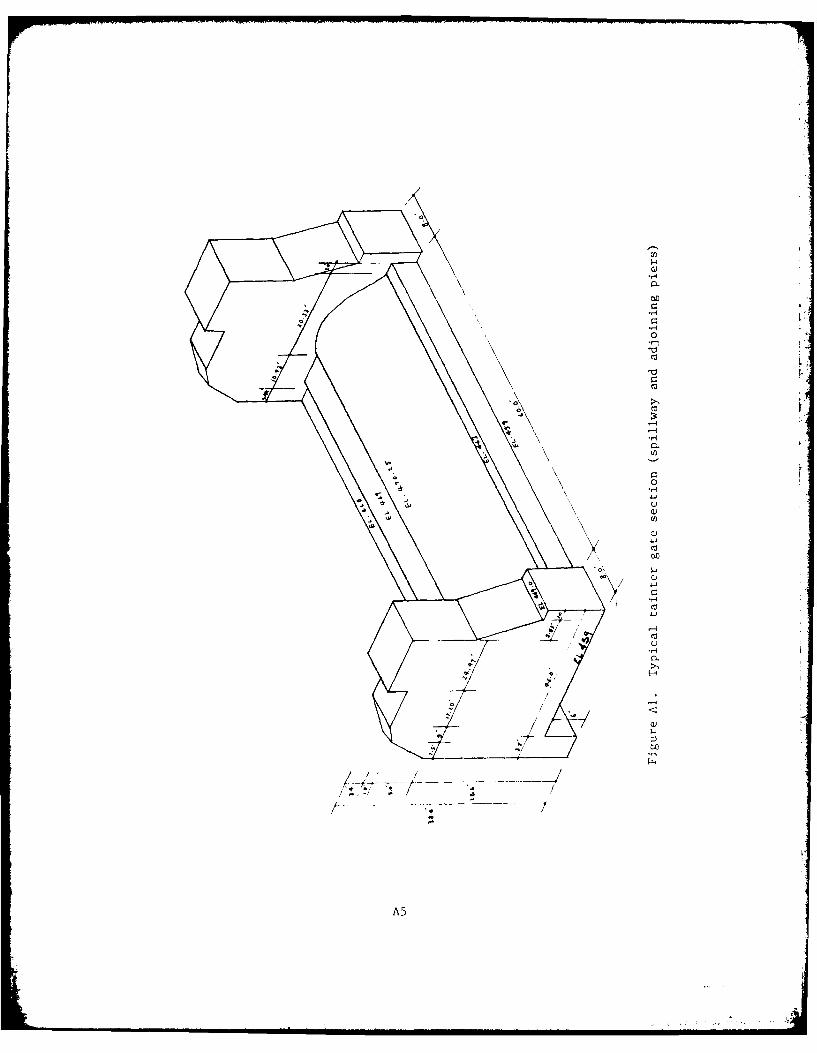
12. The typical geometry of the tainter gate monolith of Marseilles
Dam is shown in Figure Al. The construction of the tainter gate mono-
lith is such that the pier extends down to the foundation and is only
connected to the overflow section by concrete keys.
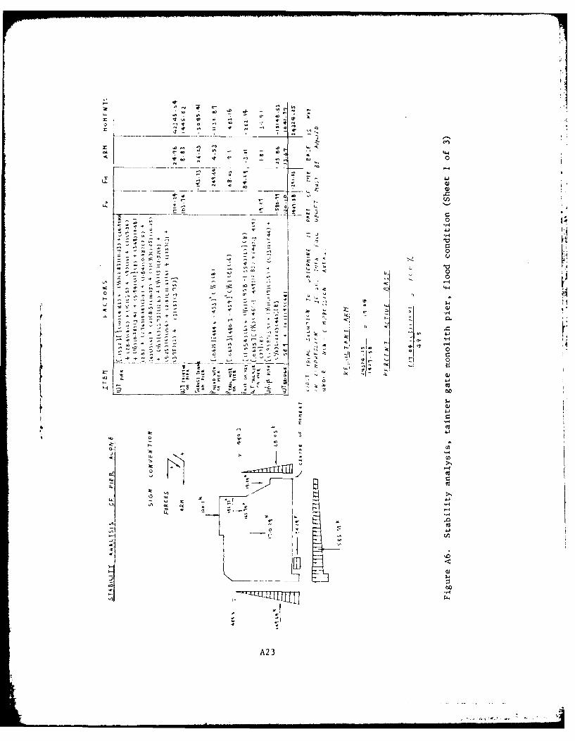
13. The tainter gate monolith pier and spillway were analyzed for
stability for the following loadings:
a. Normal operation.
b. Normal operation with ice.
c. Normal operation with earthquake.
d. Flood condition.
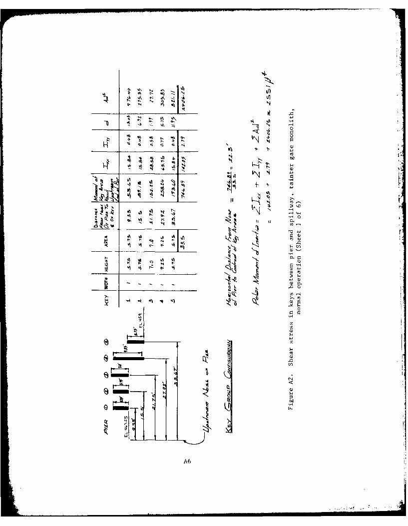
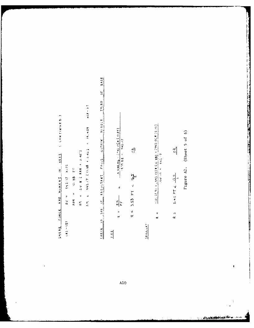
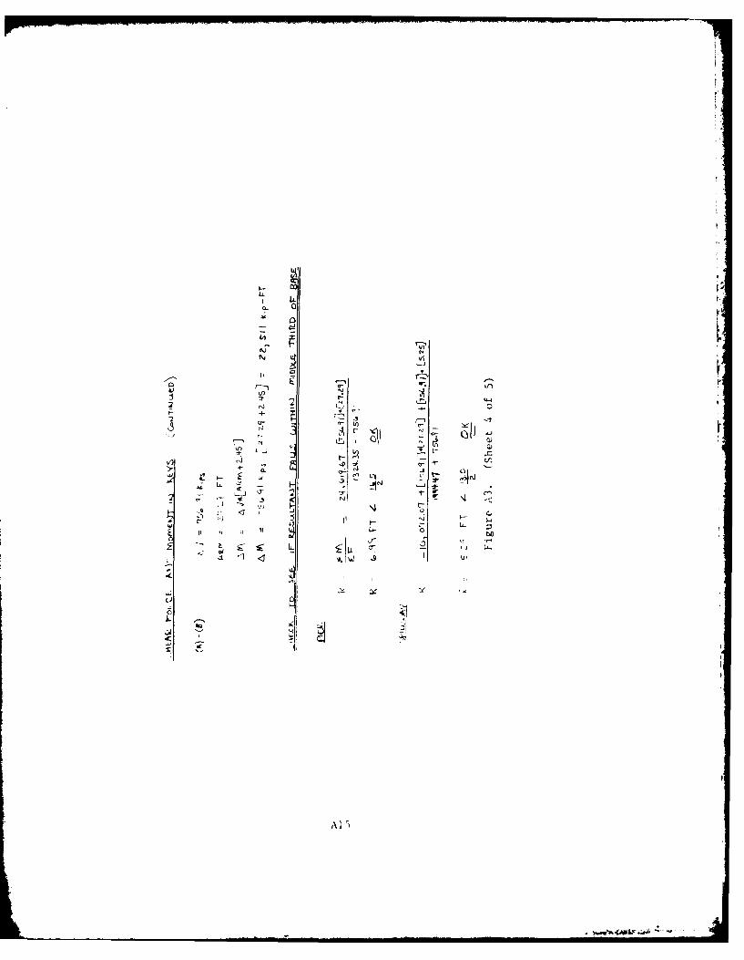
14. The first consideration concerning the stability of the tainter
gate monolith is whether or not the concrete keys allow a significant
transfer of shears and moments between the pier and overflow section in
order that they can be considered monolithic. If the keys are stressed
above the allowable limits, they will have to be considered ineffective
and the pier and overflow sections analyzed independently for adequacy
in stability. The calculations for approximate shear stress in the keys
are given in Figures A2 and A3.
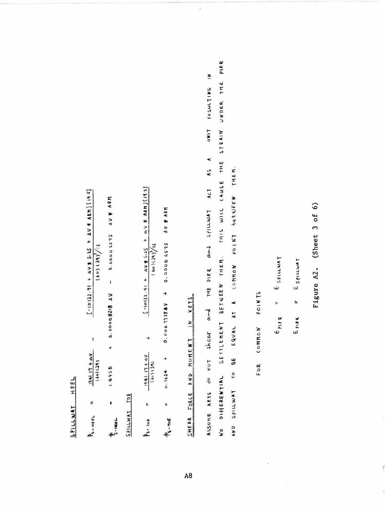
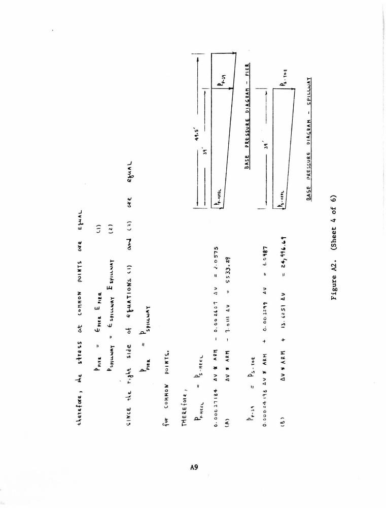
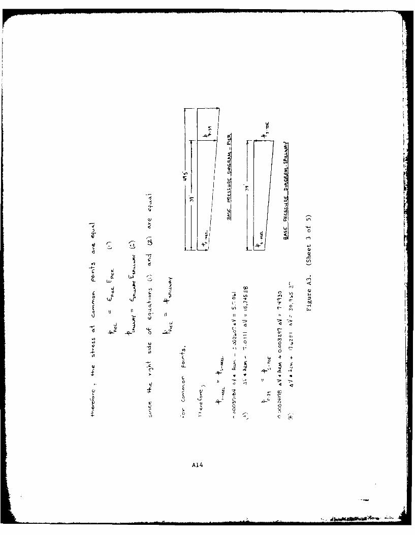
15. To determine the shear stress in the keys, the following as-
sumptions were made:
a. Keys are not sheared.
b. The pier and spillway act as a unit resulting in no dif-ferential settlement between them.
C. The strains under the pier and spillway are equal at acommon point.
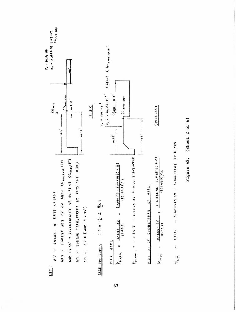
Using these assumptions, the shear force (AV) and its moment arm about
the center of gravity of the base were determined by setting the base
pressures equal for common points between the pier and spillway. The
shear force (AV) and its associated torque (AM) were transferred to the
8
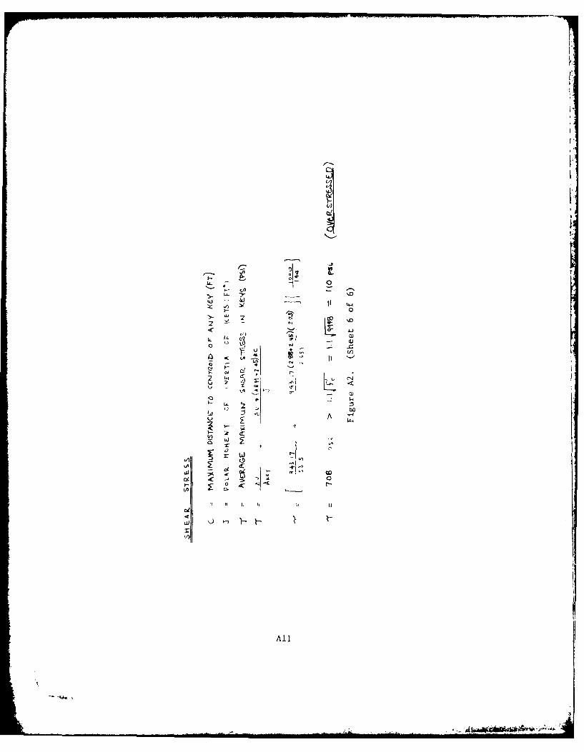
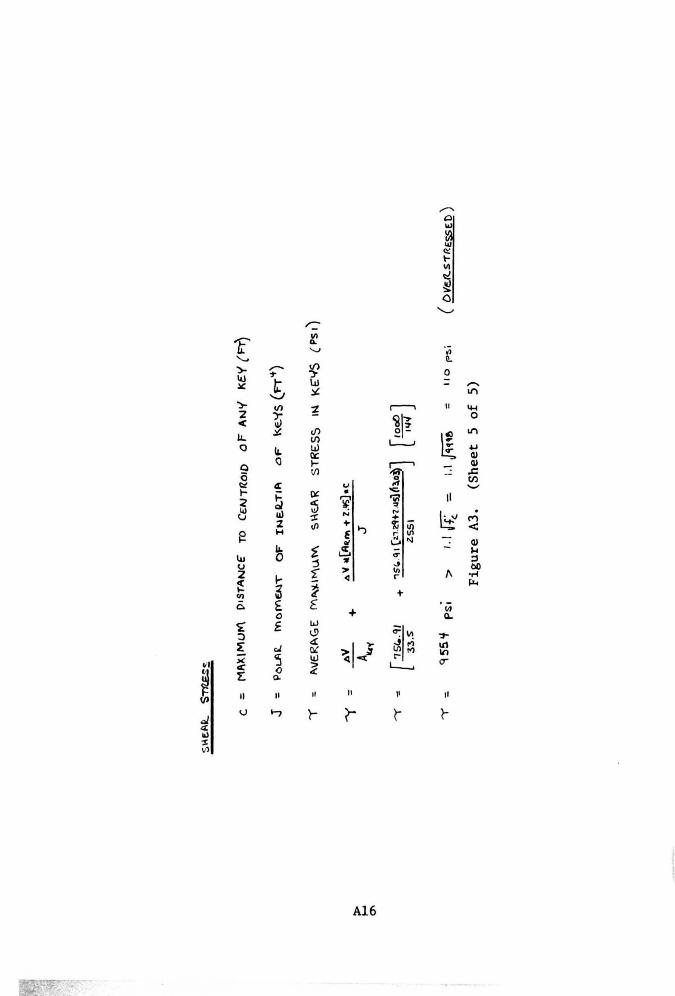
centroid of the keys, and the average maximum shear stress in the out-
side key was calculated as that produced by direct shear, plus the shear
created by the torsion.
16. The maximum average shear stress on the downstream key was
calculated to be 708 psi for the normal operation and 955 psi for normal
operation with ice.
17. The shear stress produced in the keys is also increased by
the applied horizontal forces. The contribution of the shear stress
due to the horizontal forces is not calculated because that contributed
by the vertical forces is already excessive. An allowable shear stress
of 1.1 Vr' = 1.1 v9998 = 110 psi is used. At this point it is seenC
that the keys cannot be depended upon to cause the pier and spillway
sections to act monolithic. The stability analysis must then be per-
formed for the pier and spillway as if they act independently.
Stability analysis of pier
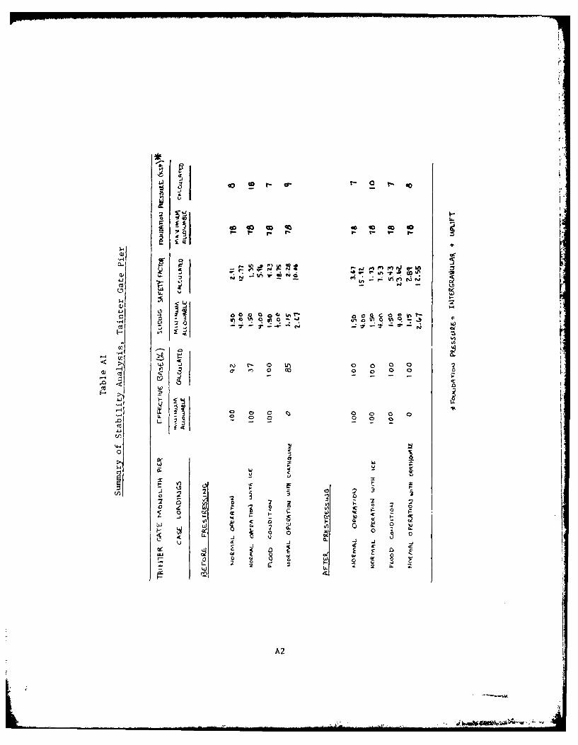
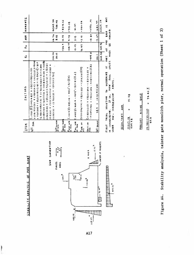
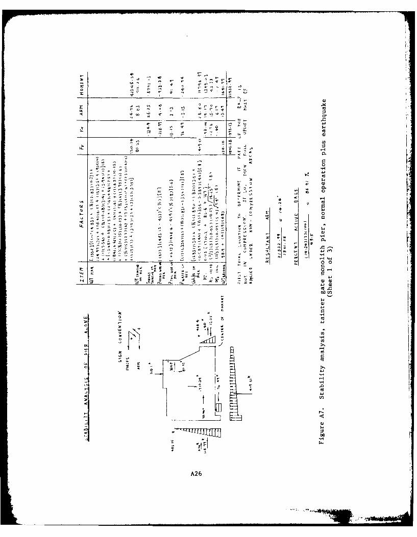
18. A summary of the stability analysis results of the pier is
presented in Table Al.
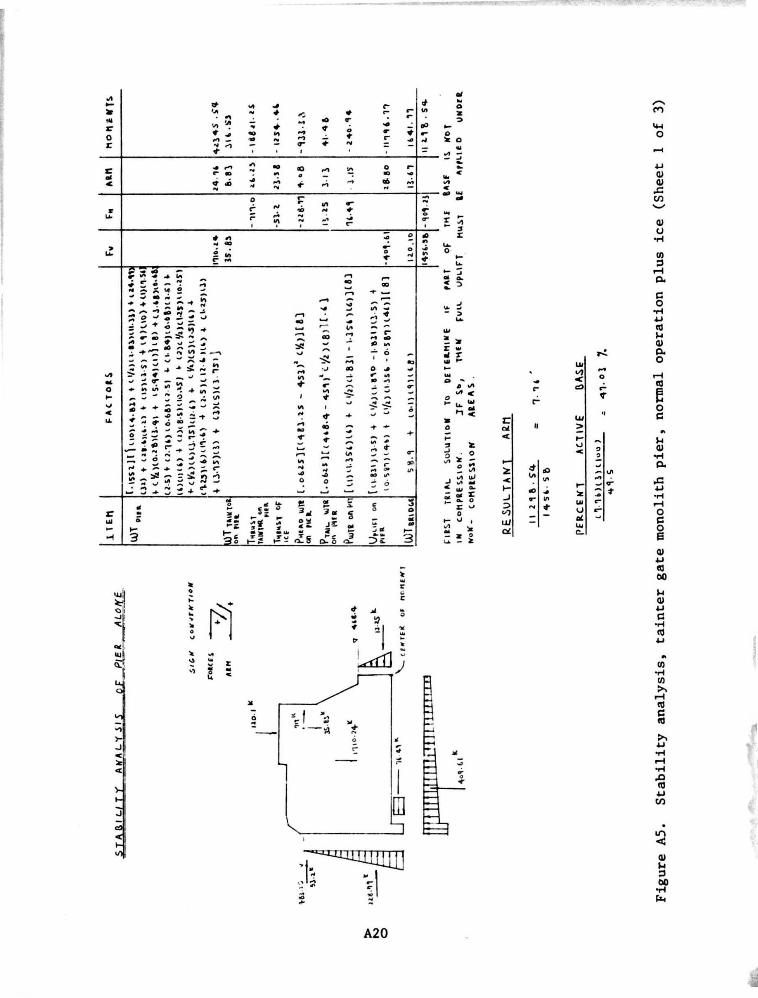
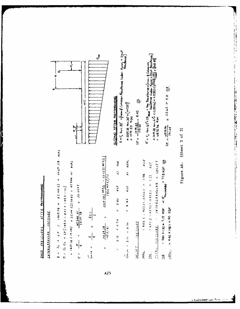
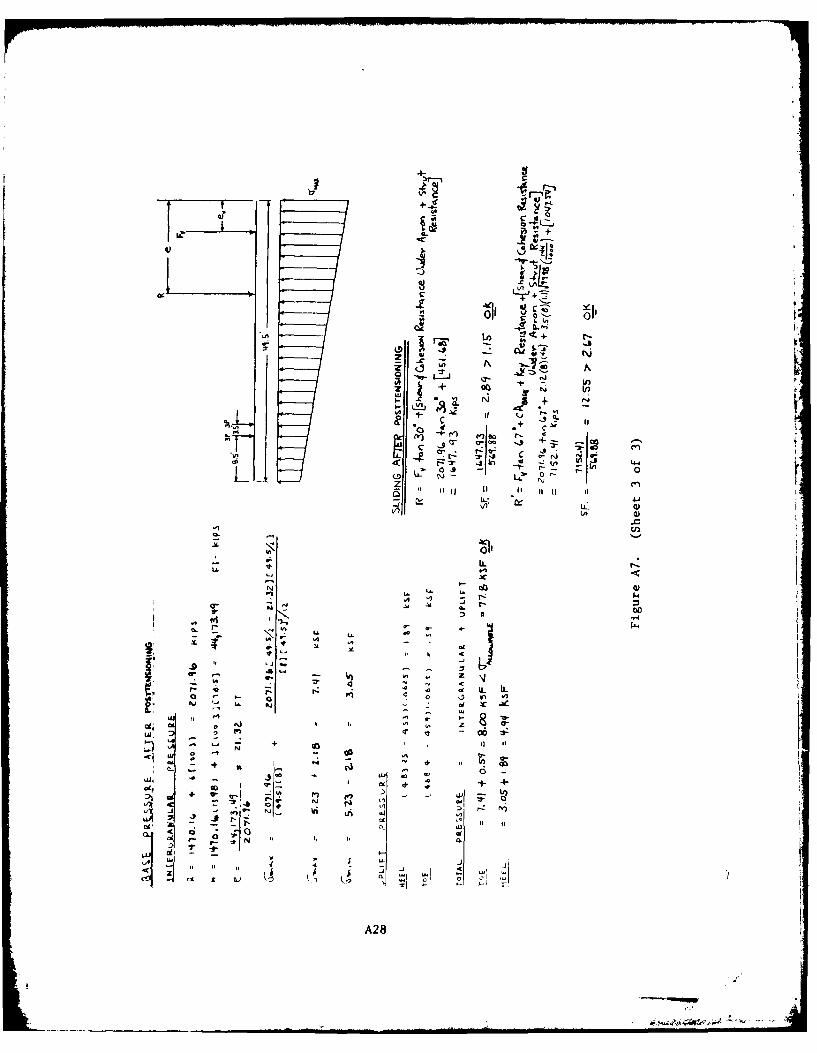
19. The analysis of the rtability of the pier alone is presented
in Figures A4-A7. The adequacy of the stability of the pier alone will
be determined by its sufficiency in resistance to overturning, sliding,
and base pressures.
20. The first trial solution for overturning of the pier was to
determine whether the total base is in compression under the given
operating condition. These calculations are necessary to determine if
some area of the base is not in compression, thereby causing full uplift
to exist under the noncompressive area. The pier is inadequate in its
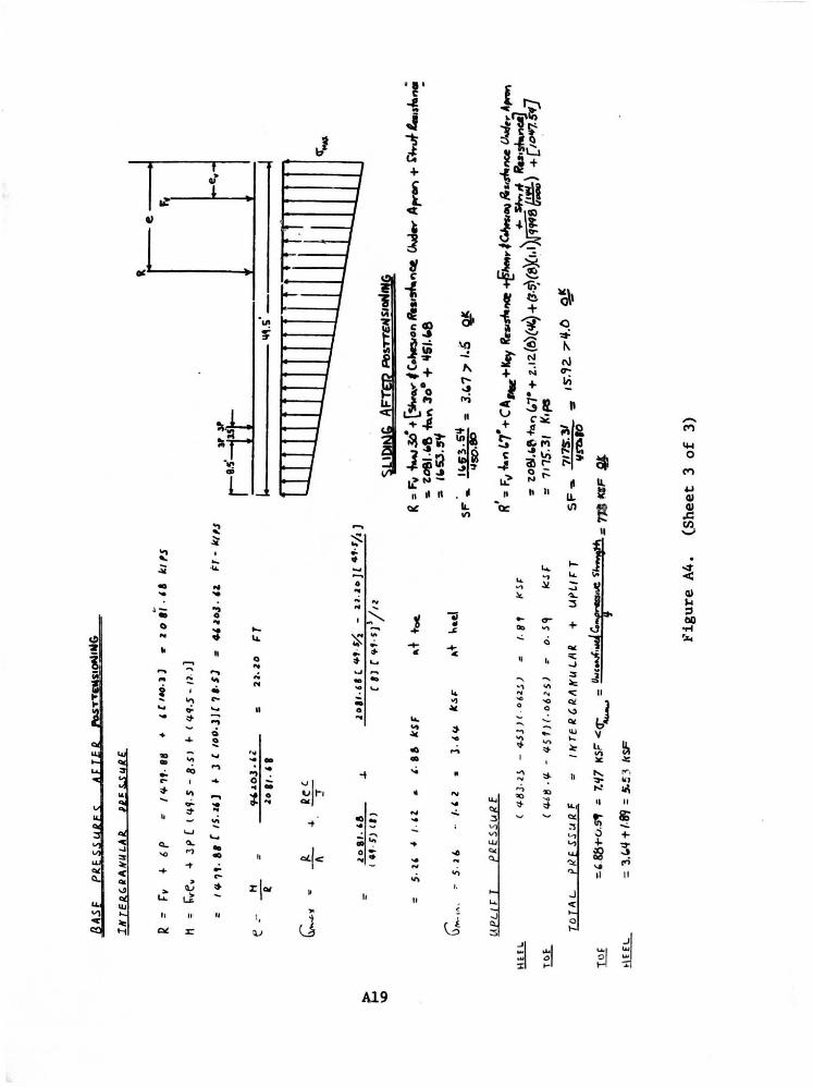
resistance to overturning. The tainter gate piers have to be postten-
sioned to the foundations to meet present-day criteria against overturn-
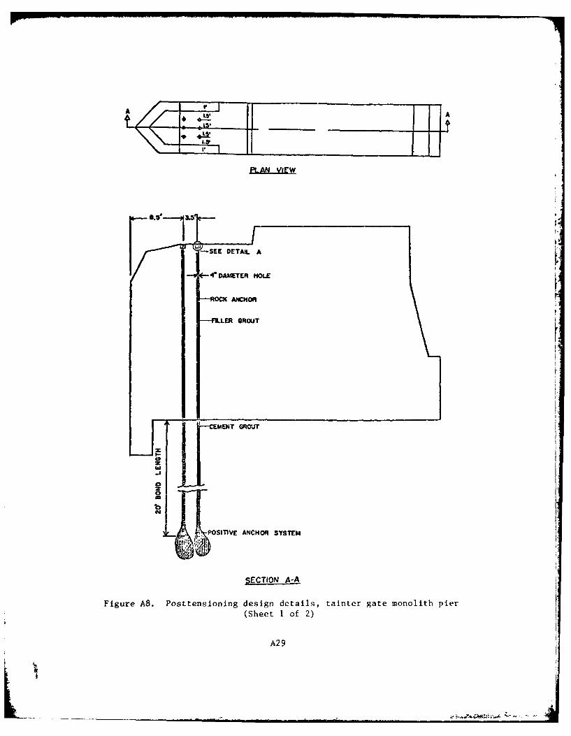
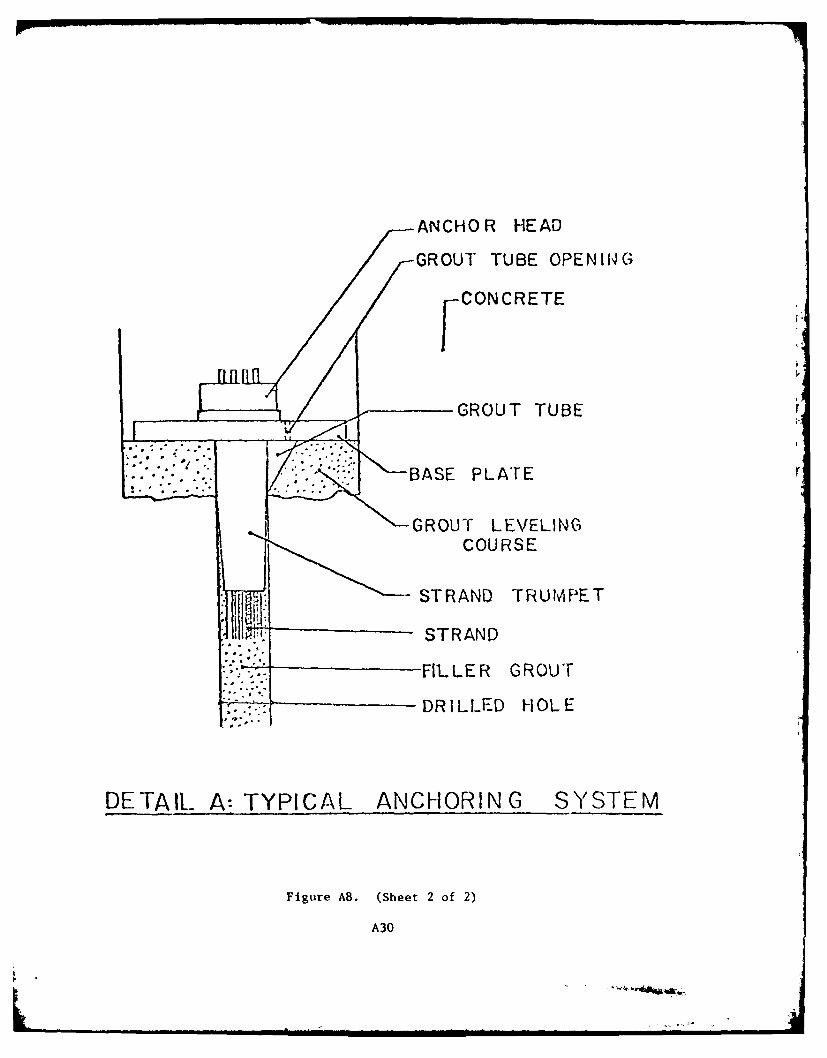
ing. The general details of the posttensioning are presented in Figure
A8. The posttensioning force needed is 602 kips per pier and is pro-
posed to be accomplished by six posttensioning holes per pier located
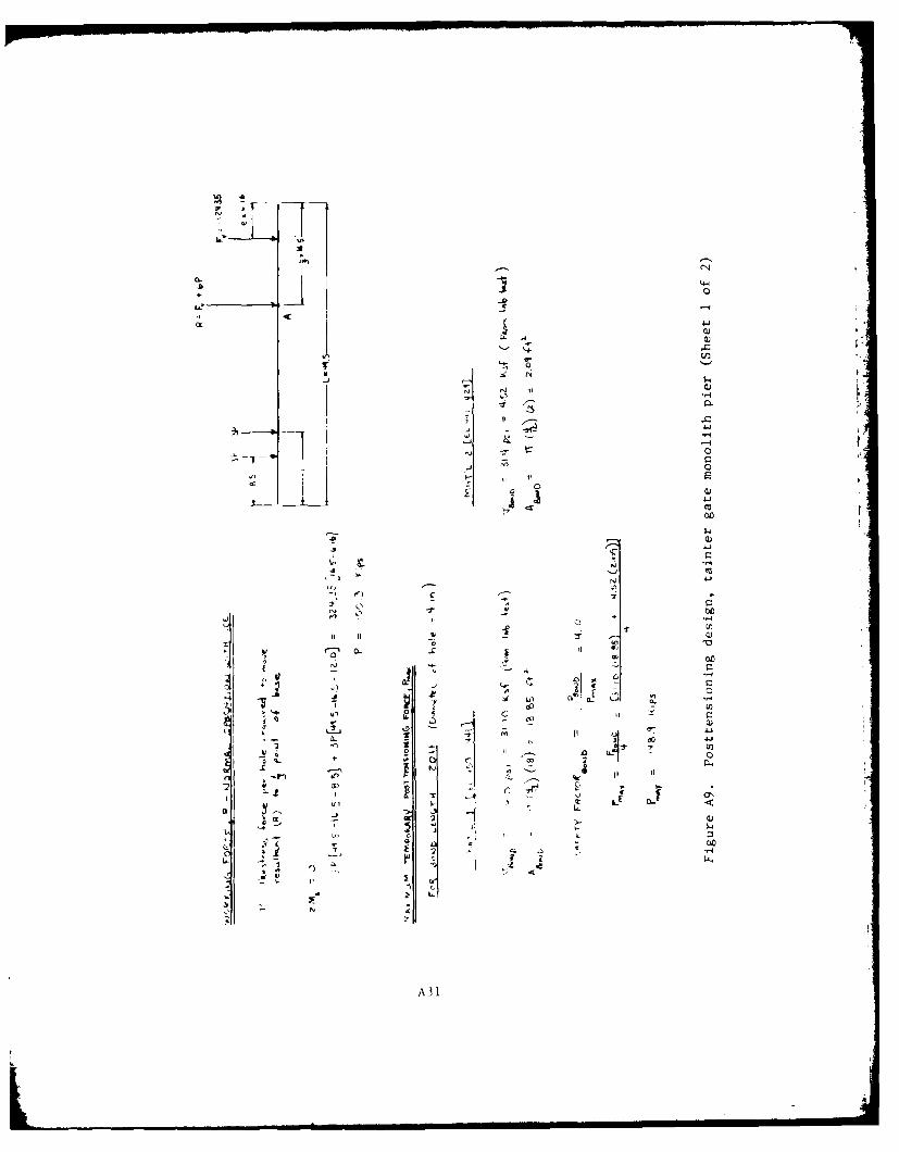
as shown in Figure A8. The design calculations for posttensioning are
given in Figure A9. After the piers are posttensioned to the founda-
tion, they will have adequate resistance against overturning.
9
. . . .. . . . . ,. . . . . . . . . . . . .. ' .. , . . t

21. For anchoring the posttensioning tendons, it is recommended
that a grout having a three-day compressive strength of 5000 psi be used.
To surround the tendons inside the concrete pier, a cement-based grout
should be used to bond the tendon and protect it against corrosion.
This grouting should be done only after there is negligible additional
loss of prestress with time.
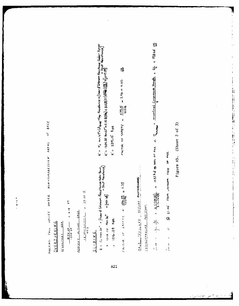
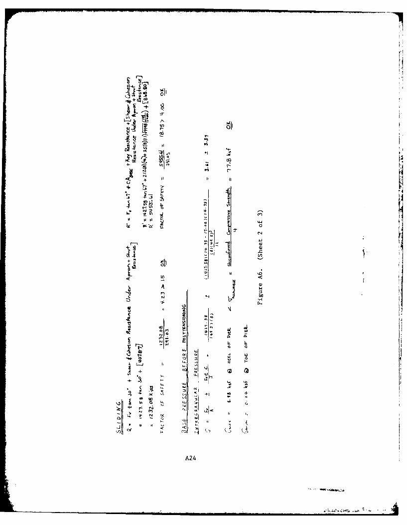
22. The resistance to sliding was evaluated in relation to the
criteria presented in paragraph 7. There were several possible failure
planes and conditions considered for adequacy of the structure against
sliding.
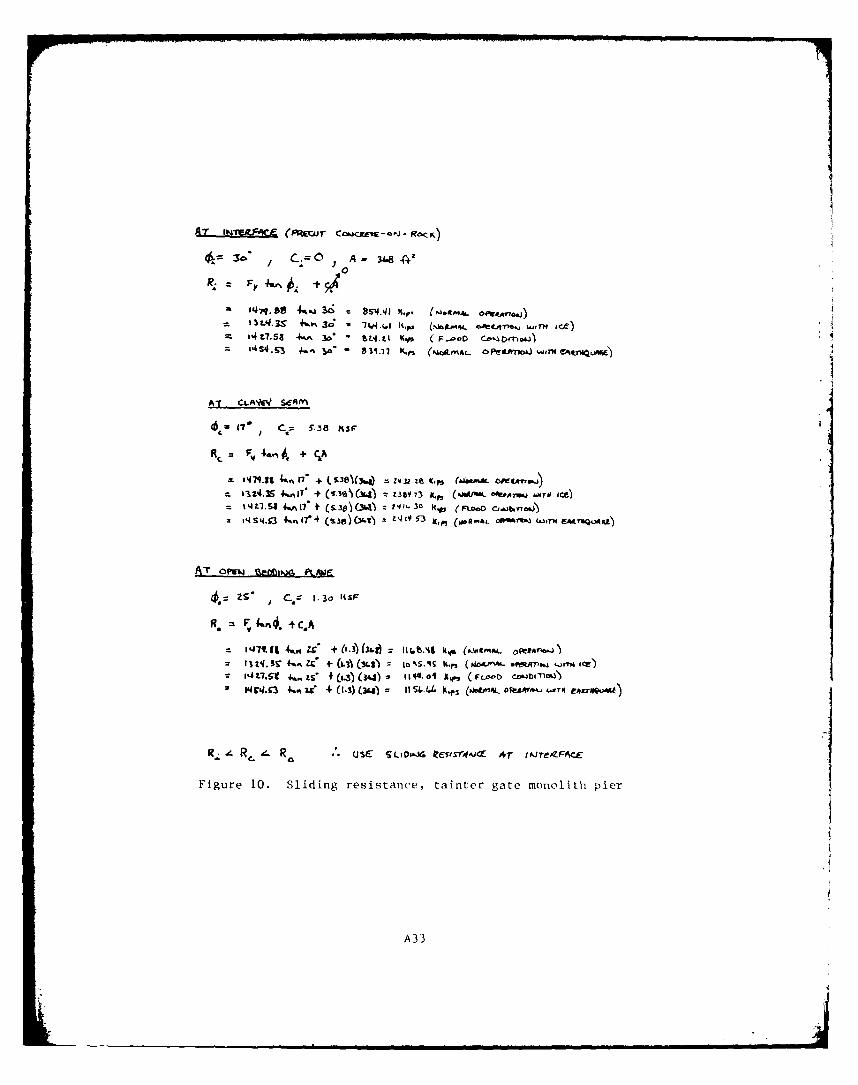
23. The shear resistance was calculated for (a) a clayey seam,
(b) an open bedding plane, and (c) precut, concrete-on-rock to determine
which governed for sliding at or just below the concrete foundation inter-
face. For all cases, the precut, concrete-on-rock governed the sliding
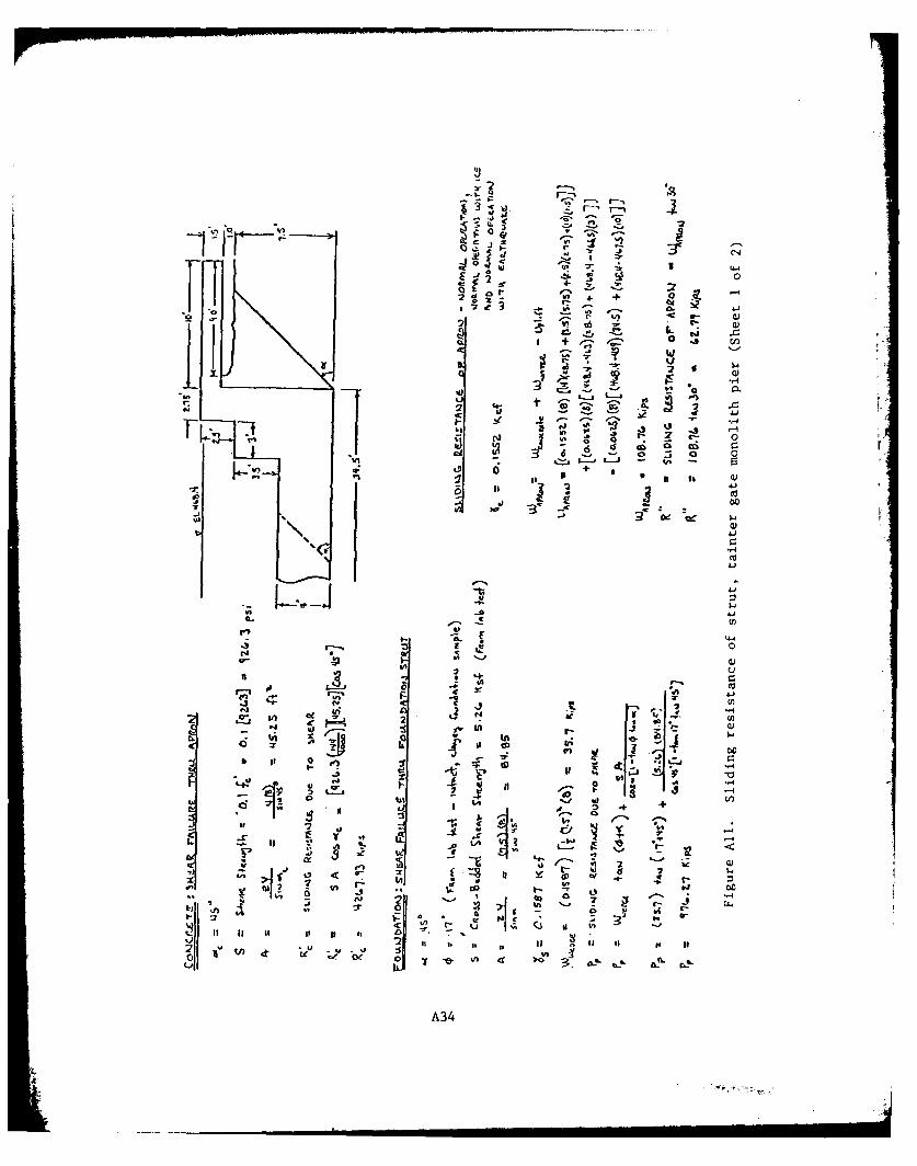
resistance of the pier, as presented in Figure A10.
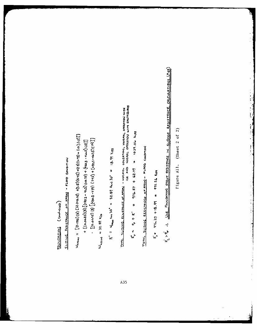
24. The strut resistance against sliding for both the concrete
and the foundation was computed and compared to determine which offered
the least resistance. For all loadings the foundation strut governed
(see Figure All).
25. Two approaches were used to evaluate sliding factors of
safety for the pier. The first (lower bound value) used the sliding
resistance as the precut, concrete-on-rock under the pier and apron plus
the shear resistance of the foundation strut along an open bedding plane.
In this case the shear resistance of the key was neglected. This ap-
proach required a factor of safety of 1.15 for normal operation with
earthquake and 1.5 for the other load cases.
26. The second approach used the sliding resistance as concrete
cast on foundation rock under the pier and apron, plus the shear resis-
tance of the foundation strut along an open bedding plane, plus the shear
resistance of the key. This required a factor of safety of 2-2/3 for
normal operation plus earthquake and 4.0 for the other load cases.
27. The factor of safety against sliding for all loadings was
adequate. There is significant scour at various locations along the
toe of the stilling basin, therefore, maintenance needs to be performed
10
on this scour to eliminate it and assure that it does not continue to
cause problems in the future. Using shear strengths of precut, concrete-
on-rock, and strut action assuming an open bedding plane and no key re-
sistance, the safety factors against sliding are 2.91 for normal opera-
tion, 2.28 for normal operation with earthquake, and 1.35 for normal
operation with ice. The only condition of concern is when the strut
action is ineffective for normal operation with ice, which produces a
safety factor of 0.85. For this and to eliminate future maintenance
problems, it is desirable to perform corrective maintenance to eliminate
the scour at the downstream end of the stilling basin.
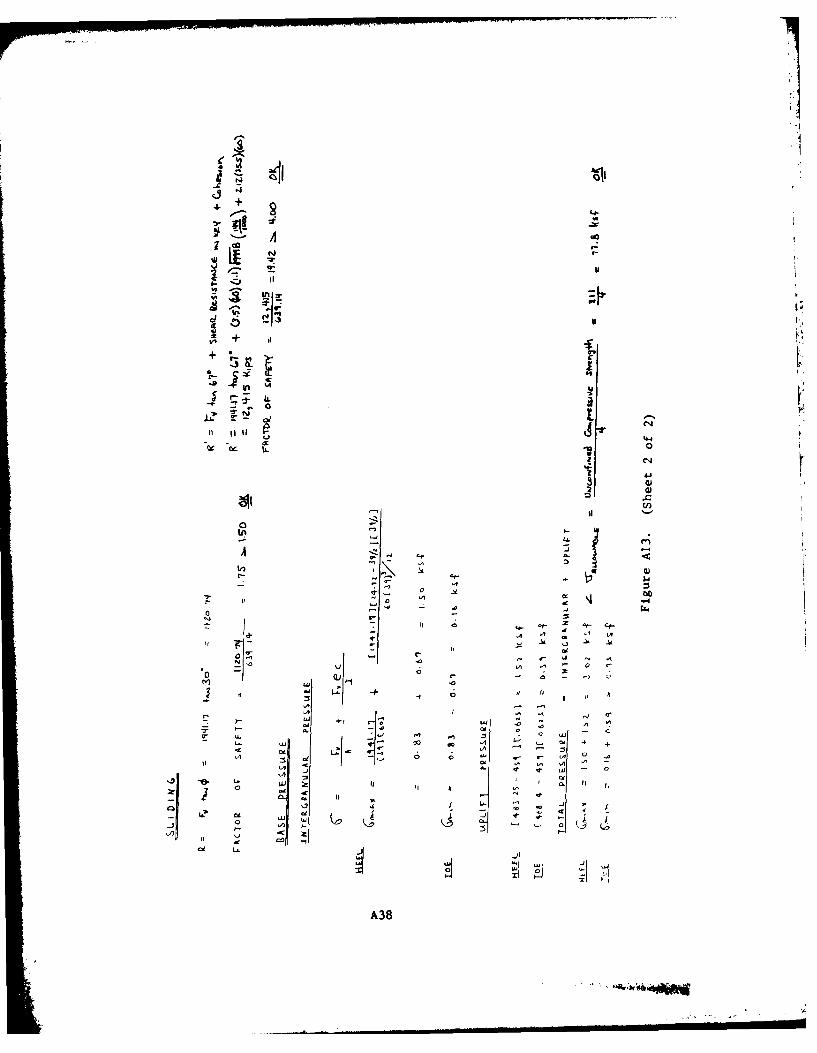
28. The bearing pressures were within allowable values
(unconfined compressive strength . 77.8 ksf)
at the structure and foundation interface. There is a weaker stratum
in the foundation at approximately 18 ft below the structure-foundation
interface. The allowable foundation pressure
uc-ti = 15.48 kst)
is exceeded before the piers are prestressed to the foundation but is
not exceeded for this weaker stratum after posttensioning. The calcula-
tions of foundation stresses at 18 ft below structure are presented in
Figure A12.
Stability analysis ofpil 1lwy
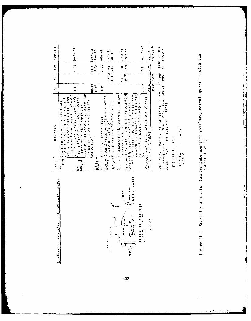
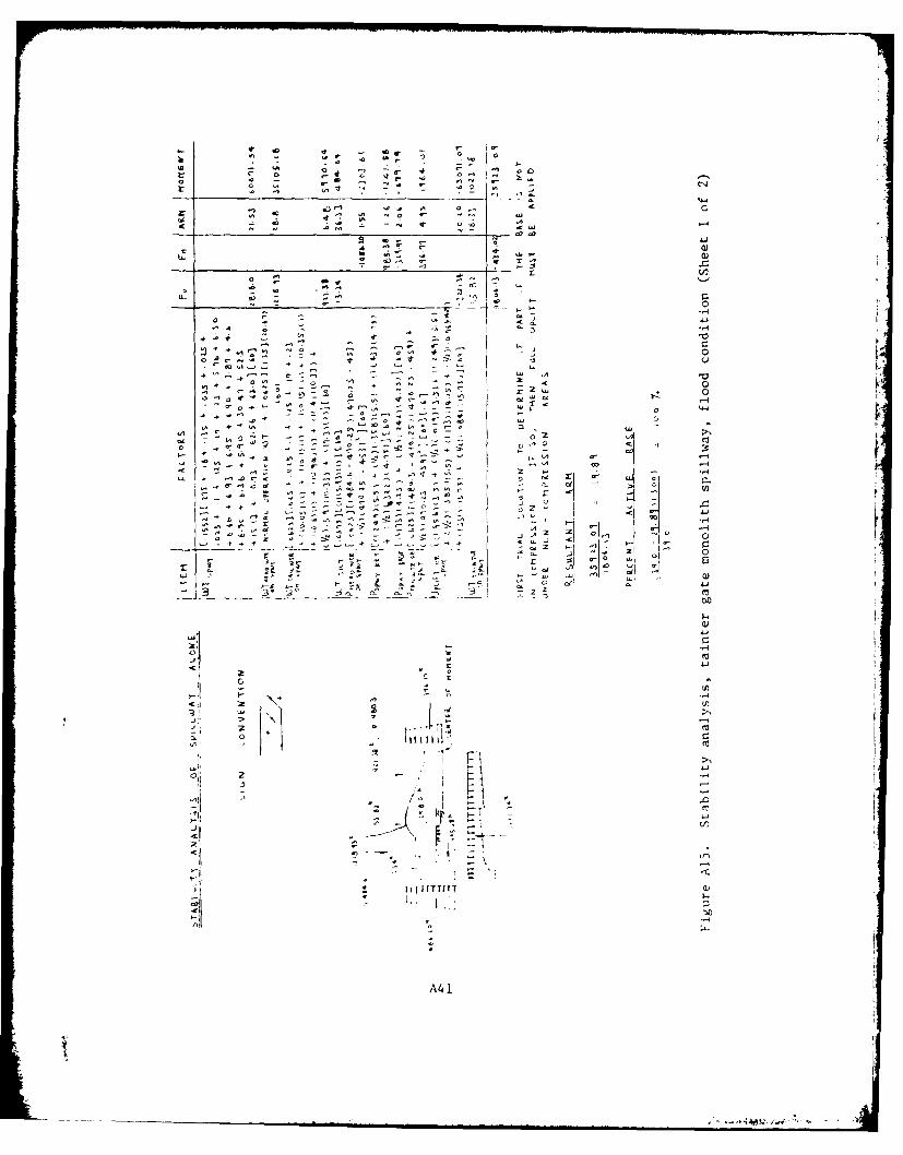
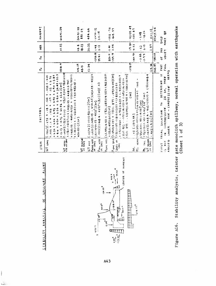
29. A summary of the stability analysis of the spillway is pre-
sented in Table A2. The detailed calculations of this analysis are pre-
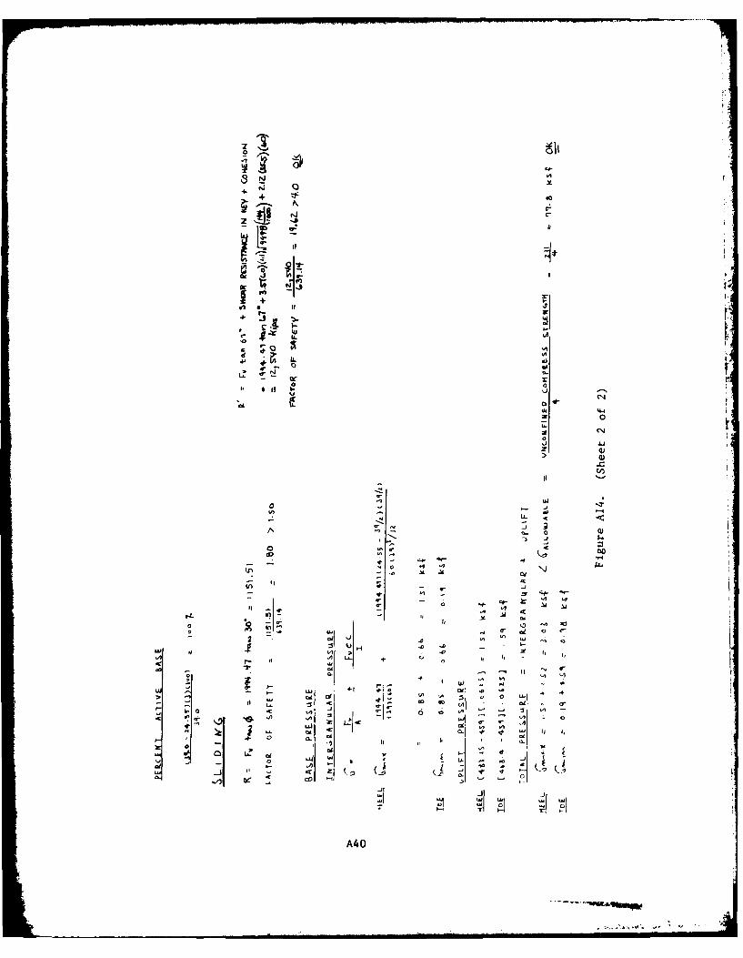
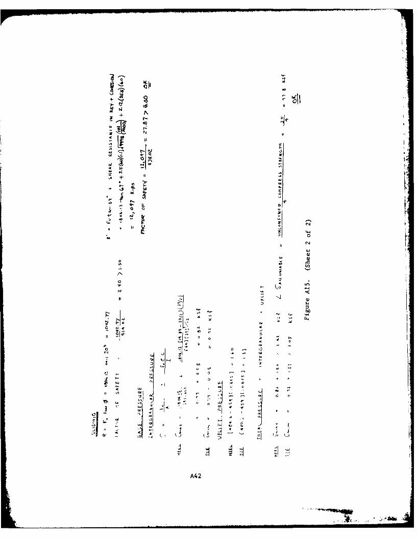
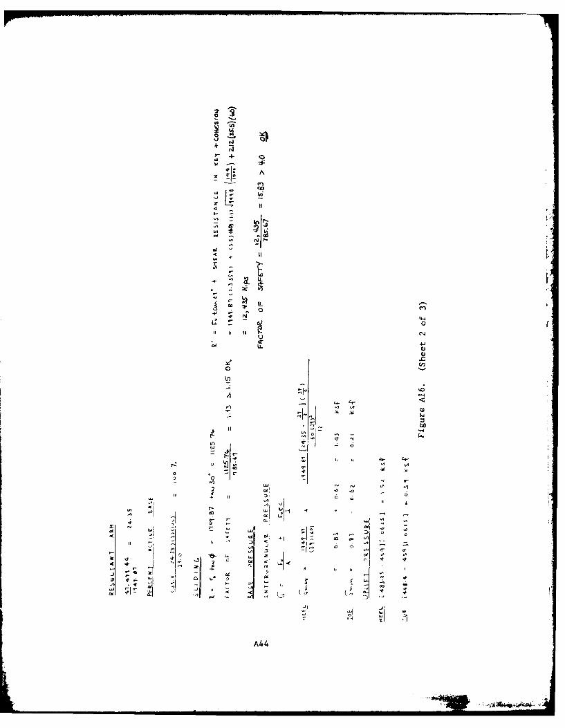
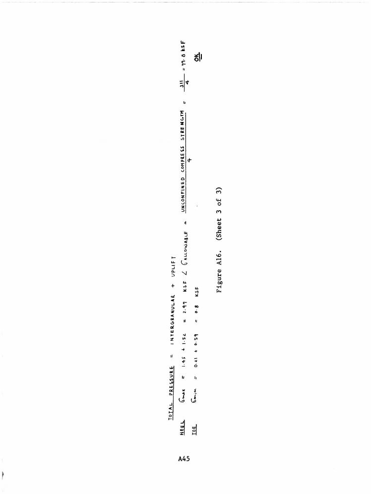
sented in Figures A13-A16.
30. The resistance against overturning of the spillway is con-
sidered adequate, as the resul tant for each loading falls within the
kern area of the base resulting in 100 percent of the base being in
compression.
111
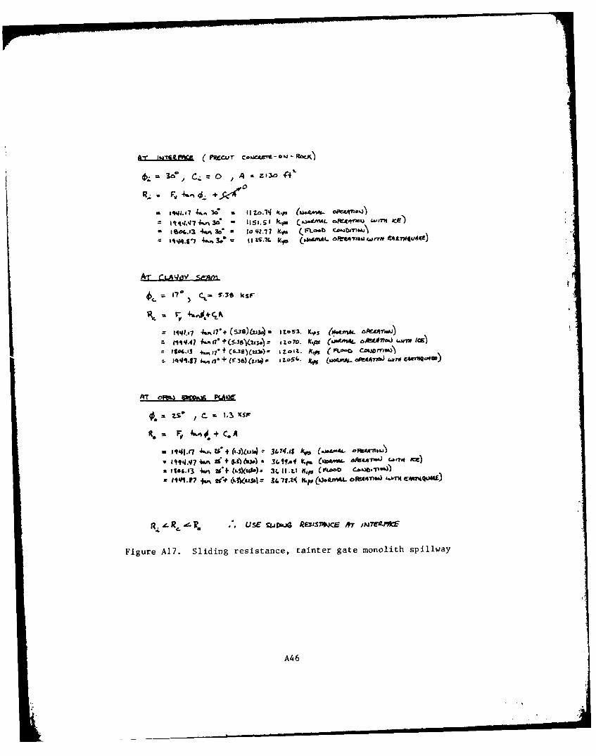
31. The sliding resistance along a clayey seam and open bedding
plane of the foundation was computed and compared to the residual-shear
resistance of the concrete on rock. For all loadings the residual re-
sistance governed. This comparison is presented in Figure A17. The
sliding factor of safety was computed for both residual-shear resistance
of concrete on rock and shear resistance of the natural joint between
the concrete and the foundation rock. The resistance for each was com-
pared with the allowables presented in paragraph 7 and thereby deter-
mined to be adequate. The shear resistance of the key and strut was
not needed to determine adequacy against sliding and therefore was ne-
glected in these calculations.
32. The bearing pressures at the spillway and foundation inter-
face were well within the allowable. The allowable bearing pressure at
the interface was determined to be 77.8 ksf using the unconfined com-
pressive strength of 311 ksf from laboratory tests and a safety factor
of 4. It was not necessary to check the bearing pressure at interface
between the two different foundation materials as the bearing of the
pier was reater than that of the spillway and it governed.
Ice Chute Monolith
33. Calculations and a discussion concluding that the ice chute
stability was adequate were published by the Chicago District (1973b).
These conclusions were verified; therefore, the stability of the ice
chute is adequate.
12
PART III: STRESS ANALYSIS
Pier
Stress in pier at*el 480.33 and 469
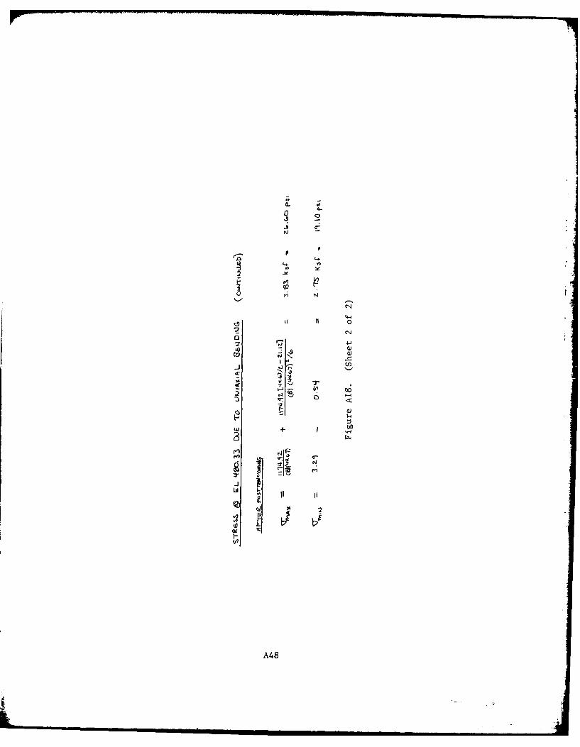
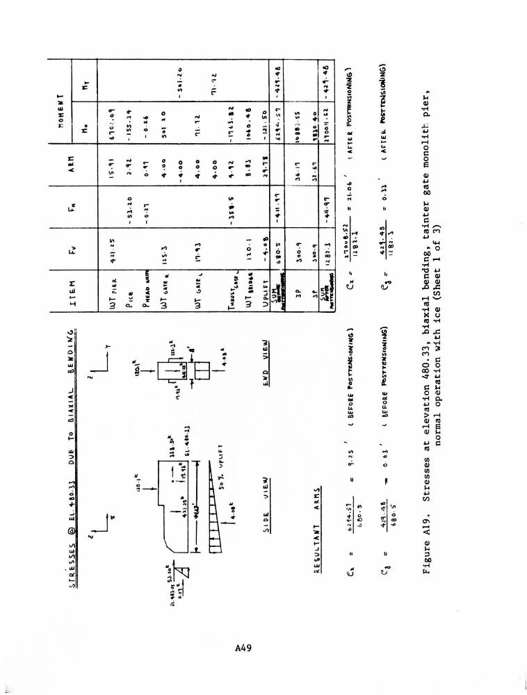
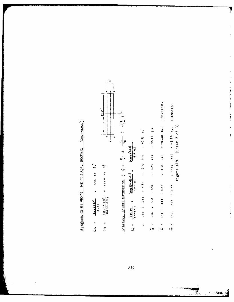
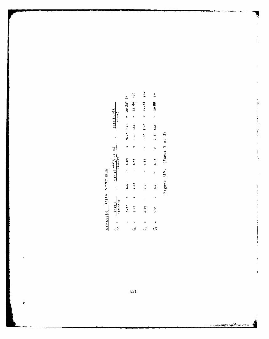
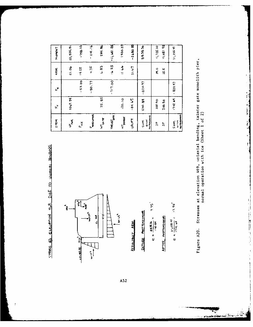
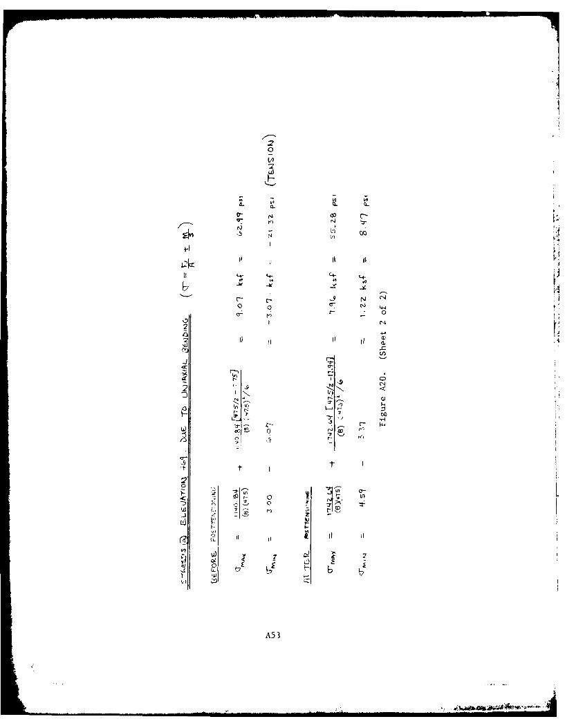
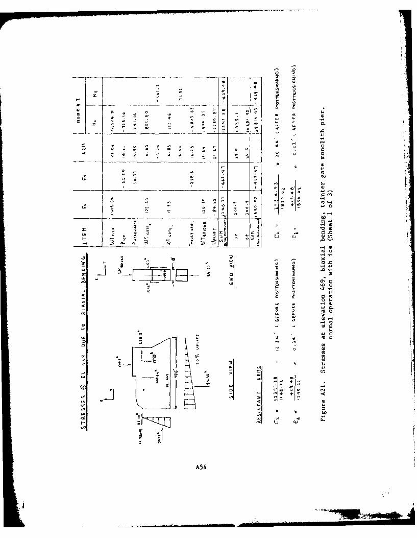
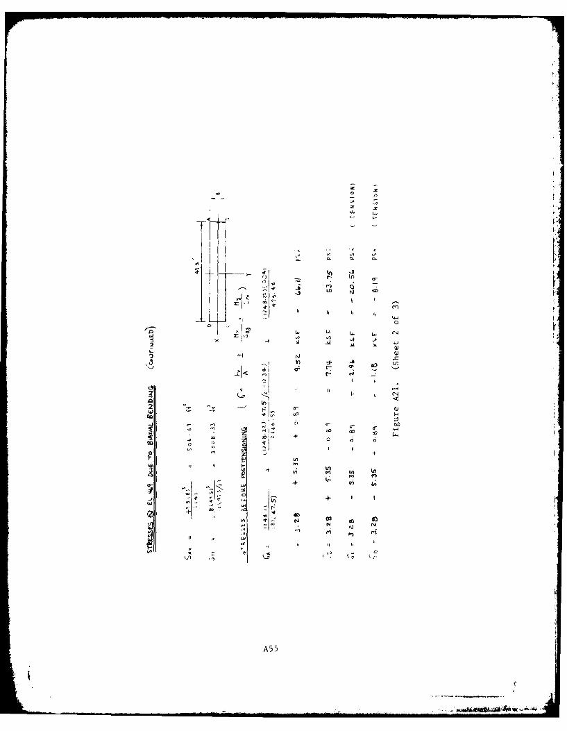
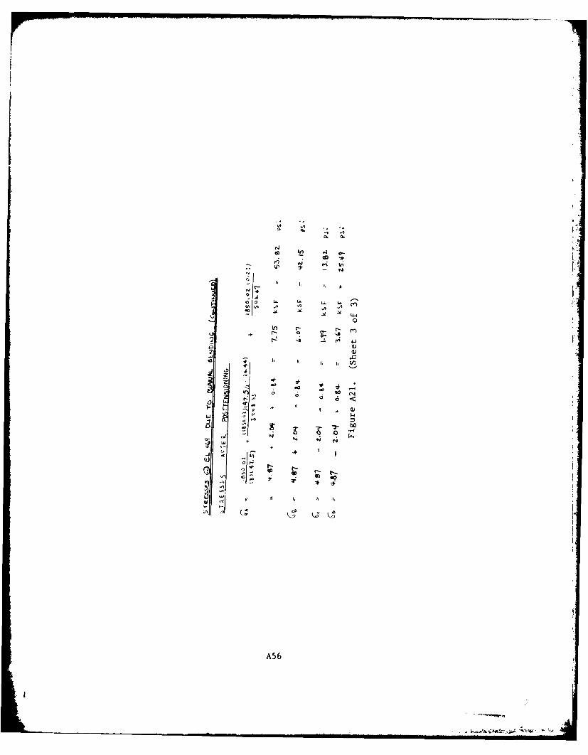
34. Conventional stress analysis was used to determine the stresses
in the concrete due to uniaxial and biaxial bending for normal operation
with ice, before and after prestressing. Details of the stress analysis
for sections at el 480.33 and 469 are presented in Figures A18-A21. In
the biaxial analysis, bending is caused by one gate being out of the
water while the other is still loaded.
35. The maximum stress values at these elevations are presented
below. Before posttensioning, the piers are inadequate because of ten-
sile stresses. After posttensioning, the piers do not have any tensile
stress and are therefore adequate.
Post- Maximum Tensile Maximum Compressive
Elevation Bending tension Stress, psi Stress, psi
480.33 Uniaxial Before -11.60 33.82
After None 26.60
480.33 Biaxial Before -16.32 42.71After None 35.35
469.00 Uniaxial Before -21.32 62.99After None 55.28
469.00 Biaxial Before -20.56 66.11After None 53.82
Bearing stresses in pier directlybeneath applied posttensioned force
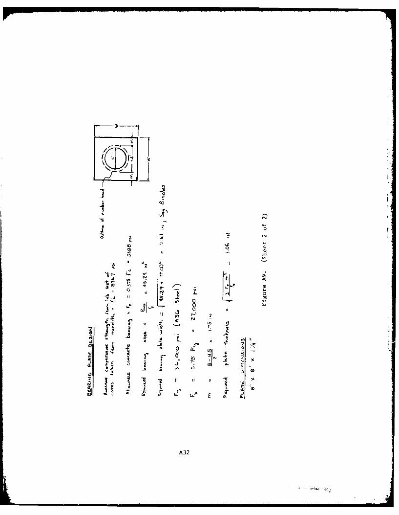
36. Bearing stresses in the pier directly beneath the applied
posttensioning force were limited to the allowable of 0.375f' throughc
the posttensioned bearing plate design. Therefore, no overstress in
All elevations (el) cited herein are in feet referred to mean sealevel (msl).
13
bearing exists in the pier due to the applied posttensioning. For this
location in the pier, the compressive strength of the concrete (fW) isc
8767 psi with an allowable bearing stress of 3288 psi. This design is
presented in Figure A9. t
Pier Foundation
Finite-element stress program [37. Introduction. A finite-element structural analysis program
(SAP V) was used to compute the stresses in the foundation due to post-
tensioned loading. This program was designed and programmed to be an
effective and efficient computer program for analyzing very large, com-
plex three-dimensional structural systems with no loss of efficiency in
the solution of small problems. Twelve structural element types were
included to increase the usability and flexibility of the program.
38. The capacity of the program is controlled by an "A" array
containing 10,000 double precision words of storage. The size of this
array can be changed to increase the capacity of the program by increas-
ing the value of "MTOT1" in a routine labeled SAP V of the program.
39. Input. Each node in the system is described by a location
and a set of boundary conditions. The location is input as either
cartesian (x, y, z) or cylindrical (r, z, 0) coordinates. Tho boundary
conditions are defined by three translations and three rotations.
40. Each element in the system is described by a set of nodes
and a material type. Other element input includes material properties
such as Young's modulus of elasticity, weight density, coefficient of
thermal expansion, Poisson's ratio, and shear modulus.
41. Undeformed or deformed finite-element grids can be obtained
directly from SAP V; at present, capabilities do not exist to directly
plot stress by SAP V. If stress plots are desired, a way to plot them
must be devised and the maximum and minimum stresses will have to be
calculated as well as plotted.
14
42. Structural loadings are input as nodal and element loads.
The nodal loads are applied as forces and moments. The element loads
include thermal, gravity, and hydrostatic loadings. r"
43. Output. The solution output includes displacements and rota-
tions for each unrestrained node and normal and shearing stresses at se- Vlected points for each element. The output units are the same as the
input units.
Finite-element grid
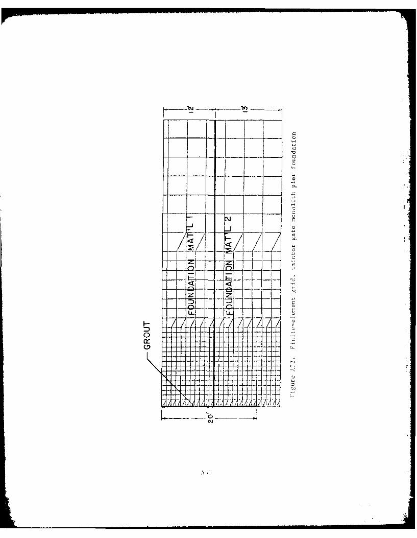
44. A two-dimensional axisymmetric finite-element analysis was
used to compute the stresses in the foundation. In this analysis a
25-ft depth of foundation was used with the prestress force being ap-
plied at the key foundation interface. The foundation was subdivided
into two foundation materials and a hole was added for a posttensioned
grouted anchor. The depth of the hole was limited to 20 ft due to the
poor bond strength of the lower foundation material. The finite-element
grid for this analysis is presented in Figure A22.
45. It was later determined that the posttensioning would not be
placed through the key. Therefore, it was assumed that the 6 ft of
foundation between the base of the structure and the bottom of key was
the same as material 1 directly beneath the key. This resulted in the
depth of material 1 being increased from 12 ft to 18 ft. The 18-ft
depth was used in computing the required bond length for anchoring the
structure to the foundation. It was not necessary to perform the finite-
element analysis again as the increase in depth of material 1 would in-
crease the volume and thereby increase the overall strength of the
foundation and reduce stresses.
46. The bond strength for lower foundation material is 31.4 psi
and is approximately one-seventh of that for the top material. As the
maximum capacity of the 20-ft hole in bond is 150 kips, the required
bond strength for the 100.3-kip working force is adequate. The maximum
posttensioned force calculations are presented in Figure A9.
15
I.
Stresses in the groutsurrounding posttensioning cable
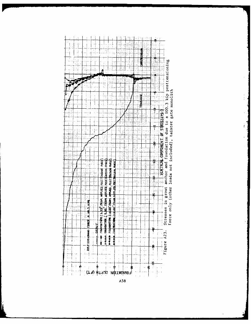
47. The posttensioned load for a single location was the only
loading applied to the foundation for the finite-element analysis. The
plotted stress results for an applied working force of 100.3 kips are
presented in Figure A23. These data show the stresses in the grout to
be 56-psi tension at the foundation surface and 23-psi tension at a
depth of 5 ft.
48. After applying the overburden stresses due to bearing pres-
sures and the overlap stresses from adjacent posttensioning, the net
stresses in the grout were 46-psi tension at the foundation surface and
8-psi tension at a depth of 5 ft. At a depth of 10 ft the net stress
in the grout was 4-psi compression. Even with a conservative compres-
sive strength of 5000 psi and the allowable tensile stress of 0.01 f'c
50 psi, the allowable exceeds the above tensile values for the grout.
Therefore, it can be concluded that no overstress in tension exists in
the grout due to the applied posttensioning.
Stresses in the foundation
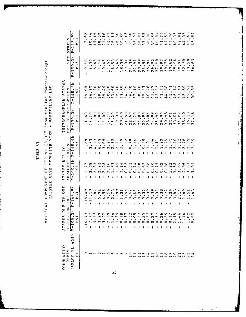
49. The stresses in the foundation due to the applied working
force were also presented in Figure A23. For posttensioning loads of
a 100.3-kip working force and a 148.9-kip maximum temporary force, over-
burden and overlap stresses were included in the calculations for the
net stresses at 3.33 in. from the applied loading. This is presented
in Table A3 and Figure A24.
50. The 100.3-kip working force resulted in the only tensile
stress in the foundation. This net tensile stress is only 0.1 psi and
is located at the foundation surface 3.33 in. from the applied load.
As this stress is negligible, no overstress in tension exists in the
foundation due to the applied posttensioning.
16LA
REFERENCES
Department of the Army, Office, Chief of Engineers. 1958. "Engineeringand Design, Gravity Dam Design," Engineering Manual 1110-2-2200, Washing- .
ton, D. C.
1974. "Gravity Dam Design Stability," Engineering Tech-
nical Letter 1110-2-184, Washington, D. C.
Stowe, Richard L. 1979. "Concrete and Rock Tests, Rehabilitation Work,
Marseilles Dam, Illinois Waterway, Chicago District," Final Report,Miscellaneous Paper SL-79-21, U. S. Army Engineer Waterways ExperimentStation, CE, Vicksburg, Miss.
U. S. Army Engineer District, Chicago. 1973a(Jul). "Stability Analysis -
Locks and Dams, Illinois Waterway, Marseilles Lock and Dam, StabilityInvestigation of Existing Marseilles Lock and Dam, Illinois Waterway,"
Chicago, Ill.
. 1973b(Jul). "Stability Analysis - Locks and Dams,
Illinois Waterway, Marseilles Lock and Dam - Appendix E - StabilityAnalysis of Dam Masonry," Chicago, Ill.
1973c(Oct). "Illinois Waterway, Illinois, Marseilles
Lock and Dam, Periodic Inspection Report No. 2," Chicago, Ill.
17
t.i
APPENDIX A: STABILITY AND
STRESS ANALYSIS DATA
Al
a. aca4I
2 -6o Ii
CD~~ - I- in a 0
7- 0 .. K
-o~f
C131
_ CD
0
J-))
0 L
Li -
A2U

u *
V.4 "Z~
04 w
JJ o
L. .
JCI
4-4 4-0N -
al
4 0.
Ooo
I.. ~ 0 3
F4 0
cr tr . . . .
C'-4-4C CccC C C C Cl.CCl.( C4rN Ci-4 Mr-C MM
C-
C- I Icr
C1 - . Ul~C %'C r- M aC -- C ,CNC. MMC c -II n I'
04 P,. oo .U-
CW C C- C14 4 (NCN w -C 'CCC -C. --,T TT- r
V- r--
E C~ C CtCC C. .C C. .C . . . . C . .-. . . . .
C- W C
I L C'C -. ( C-"C,C -4C C CC C -1 14 4 CiCU (f. " I - -
L C C :7-CZ
Z-I r- C nC CI C 7 r , M, L NC CV,esC 17'
rf C C r- L O :
od~
wA
ILI.
4"J
4
4-
"-4
A5
~' 'A ~ if
'44A l_ _ _ _ _ _
,
~-- 4-4
4 --9
Q )
II
I.))
'fIdd
A6
>
......,
!:..
U_:
6
\)
:::
!>tH.A~
II(
I<E
TS
. tKIP~)
All
t1
Ho
t1E
ll1
AR
.M
o~
bV
A
lloV
T
(C
.PIU
aA
!.f
lO:T
l
Alt
\ t
2·4
5'
= E
t.U
I(T
iliC
.iT
Y
OF=
AV
A&
<>U
T C
(,lt
ET
!.tfl)
t.M
:
ToR
.QU
E
Ti.
Ati
!.F
E!t
ll.E
O
~T
kET
S
C.F
T-
1<-!P~J
AI'
\=-
AV
I[A
IU1
-+
2-4
S'
)
H<i
.E
PII.E
S.SV
R.f
s lP=_f_t~)
p.
-I
PIE
2.
~P->tHL
t:>P
-H
UL
.
Hf:
EL
=
14-1
,·8
& -
AV
8< 4
-9·5
)
(1'
\ 104
4-
Ot,
-
l!V
f A
lt\ ]
(14
.,S
J
tt)t
'\-~·Sl1
/l~
-O·
SE-1
7
-o
.o
o2
S
AV
+
o.ooo
~of>
o,A\
111l
tll
Pt.E
il.
AT
lf
O
ou
.lN
'ST
ilfA
M
OF
HH
L
PH
, 14
1,.
&&
•
All
8<
41
-S)
+
t 14
.04
+.0
'-
4\l
f. t.
tll)li~
·ZS)
t8
) l4~
·Sl1jn.
(G.k
tf~
~ -----
ll·~ ---
-:
14
.'1
51
-~~
.za'_
1-1~
-S
( <>,
n t•
H
-11-H
S
~
r.
• ,,4
,.,,k
j H•
: k
-1
0, Ill
., I
CG..,~~
11.-
1'
x-
C.C.
'-P
•T l~
t
SP
tLL
I.V
A'f
fP-
"!.9
& . 2
I Z
. I
-o
.oo
zS
2S
llV
-o
.ou
ol1
1.2
l o
v
i!
AR
M
Fig
ure
A2.
(S
heet
2 o
f 6
)
r,:
••n ·••
11
. ~
14,0
44.
06
(
A6
oiiT
C:E
. l'ltt
IIl
li)
I. .w
--1
l ~~OUT
(. (,
. S
ful
I4S
f )
~
~PI L
Lil
iAT
~~-l
lffo
..
~-I~L
.
S~li
..LW
~'\'
~s-
tot
..P ...
~£
I"\ E
EL
= .. TO
E
IHI
-1'1
+.t
.IJ
lhll
3'1
l
1-4-~se
1~11
-l'
ltr:.IJ
l~o
) ll
"'l
o.
lb
34
. 4
(-to
i:H
·'II
t
AII
·S·l
..S
+
AV
t Alt1
)[1~
·~)
l6 0
) ll~) /
• ~
+
o.
oo
oo
8Z
I8
AV
0
· 0
o o
0 4
S 1
5
A V
tl
II
~ 1'\
( ·1~>1~1. -~I
+
6
V t
S-l
S +
c.
V 1
C 11
Rtlj[
l1-5
]
l b
o ll
l~ )f
ll. +
0.
Oo
o 1
11
5'6
V
+
O.
DO
DO
E.
S1
S
bV
f
1121
1
$~fAR.
F'o
lC.E
A
I(O
h
O.t\
_E I
( l
IW
lcE
\'S
AS
SU
t1E
kfH
d
o
lfi.)
T
~hcc.
r o.
-J
Ttl
f P
lf ~
O.""
.l I>
Y I L
L.I.
tJ~ 1
AO
AS
. II
V
lfiT
r e
S,U
L 1
I I
f(,
Ill
t(o
O
i+fE
itE
h'T
IAL
S.
E T
TL
E.t
iE.h
'T
SE
TIU
E.E
N'
Tt1
Ht
. TMI~
WIL
L
tii
iAS
.f
Tt-1
1:
S.T
R.
flll
'( lJ
iii'O
Eil
Tr1
f.
PI£~
fl II'
0
S p
I Ll W
II '1
' TO
~E
EQ
VII
L
A1
A
(ON
I1o
t.'
~o I
WT
l>e
t IV
FE
W
Tt1
E.t1
.
FD
R.
(o
t1tt
o W
P
Oi
t( T
!>
~ P
lf R
. ~
SP
IU.I
UA
'f
E. PI
H.
=
~ S
fiL
LIU
AT
Fig
ure
A2.
(S
heet
3 o
f 6
)
-t~~u.fon 1
~t.
s.-\
u ~s
c.
.t to
1"11
'1 o
N
P<.)IIH~
Cf.¥4
1. E.
\-14 ~
L
P,.u
. .,
t
Pil
l.
E. P
itA
. l
l)
~~PI
~Io!
AT
., E:
$p
iLL
\oiA
l E
Sl'l
LL
IUA
T
lll
<;I
tHE
. t~ t.
r,a
L.t.
std
e
o\
42
fUA
Tio
Ws.
U
) M
..J
( l.
) vH
. ~~AI_
p ~
\> P
lea.
s.ptu.~o~Ay
{<>r
co
11M
o w
p
ot 1n
~.
ltiE
Hfo
u 1
~
l'l
41
.5'
I I
~ ==
I>
P·1
1H
L
S -
IIE
EL
o.o
oo
l11
l14
A
V
-II
111!
11
-o
.o
ol-
40
1
/lv
=
l.o
5"7
5
[!.,.~
I P, • .,
l (I\
)
/;I}
,
Alt
1
-1-
0 Il
l A
.V
.,
55
33
. <t'1
~P-1
' =
~~
-T
o£
~~SE
PR
.E:S
SV
I.E
D
IA
,lA
M
-P
IH
o.ooo~41'li,
AV
t(
AU
\ ~
o.
oo H~
1
t.v
6. 0
'18'
1 .lq
l e. )
~V
t1AII.t1
+
1!..
'zsl
A.v
"'
a
41
Cl H
.. c.
1 b "
"' l P, ,.
,
BA
Sf
PRE~SU
II.E
01
A4
RII
H
-~PILLIUAl
Fig
ure
A2.
(S
hee
t 4
of
6)
LuI
Inn
w cn
AL Li
w -~ -00
A10
'IICY 13
I-
LL -~ -All
- (AAL

T-
0
r- -
N
£ C 4 4~o
.4-
tj:3
0
- 2
ZI I
0 Q) 0)
:ozo
100
Itw cr c
> o 0 ' 0 idIt -J~
c-L,j a: ;J44
Ic . i 0b-
L~ + LA12

9L
U?-
4 (n
t .9
jI 3 L L*> r--
L6 'X -6
-a: aO.
-. 0
10 ,-i , 13'. i .- . - £ ~.+-
+ +7m :.'4 ~
-. 1- i -
cr a,1ii LO -cd~
6J c
dl ~ 0~p-10
- 0 4A13
fit
4-r
Q)
-~44
Lii4 I-r~
A1
Q- 0
vlN)
- -
SAI, 5
>
1-'
a
-
S~EA~ S~s.
c =
M
I\X
IMU
M
DIS
TA
NC
E"
To
Ce
NT
Ro
ro
oF
AN
V
Kc'(
{~
J :
Pot
..A£.
IY
'Iof
'('I
~T
OF
IN
E.R
..T
JPI
DF
k.
E."
{S (
FT
'+)
I =
1\
IIE
RA
GE
rY
\"'~
1"'\
l.l~
5\
-\E..A
R
ST
RE
SS
lt
.l
KE
lJS
(
Ps
IJ
--y
=
i!>V
+
A" ll[
Ait
ft'\
1" l
.'IS
] •C
AV
4'(
J
.....
.,
[ 1
51
..'11
+
.,
5(,,qt
(z.1
.~t1
.115)~~0~1 r~J
33
.S
Z.S
SI
114<
/
""(
:::;
q
ss'f
P
SI
>
~,, f.
f:
1.1 J~1~tl
=
11
0 p
:.i
( DV~ttS'TRE~ED)
Fig
ure
A3.
(S
hee
t 5
of
S)
---
> ,_. .......
5IH
!L
!ll' AN~Ll$\S
Of
f>lf
i A
LO
KE
ql)
.l\
Ht\
-1,
11
10·
1"'
.. ,., ..
S!"
W
(.ot
tii£
11'T
/04'
roRc£~
AlH~
_+?f
.
Is-. lS.
l 111
0 1~·
v
4•1
·4
~---.,
...---
---~ ~--
11 •
s"
I E
3--,
~. 4
1'
\...
. tU
11
'-O
f II
OII
U I
S
llfl j
fff \
Ill f
II I
I I I
I I I
I I
I U
lHI\
I=H
l o~s.
fv
F"
A tt
l t1
0"£
1tl
1
WT
PIU
. L
•sst
1n ll"
)l4
.\l)
+
ufl
> l
l·tl
)ll
t.\1
)
~ (
14
.11
llll
l t
I >
8 .•
1H
·l)
t li~)I)
.Sl +
1'\IU
•
+ ll
)t1
·S'-
) ~
( l/t)(O.I
'611l·~l
~ <
S·1
'1)U
l}t
&JI
{
l.l&
!lO
.U)ti
·S)
t (J
.16
liO
.&&
H>
·Sl• <
1.11
11
to.•
IHI.
S)
t ")ll
\14
) I
lllli
·S)<
IO.l
$1
+
(l)t~
lH~)liO
·lSl +
t
l/1)(
6.)
( ).
1S
)Ul·
O
t t
1 /.l
lS)
ll·S
llll
t
o~
.IS )
(41
11
1 .•
> +
I 1
·:<)1
ll
.,ll
f.)
t
(I.
U )l ~~ ~ \l'l
Sllll•
t lH
Sll
l·1
H}
,,, ..
, .. ~~
. '1
1.
4ll
45
.s ..
W
Tu
1"""
O"
flft
. 8
1.1
$
a.u
'J&
e.o
ll
.. ~~.~~, ,.,.,
. ·lll
·1
u.•
s -8
3•'
1-'l
O
M
Jil
l.
p_,, .
D
'6l1
. Lo
t.>
SlC
t48l
.~S-
4!;~/
t'ltl)[l)
Oftt
llll
-u
e.,,
•·
•&
• H
l-1
11
P1A
IIo.
"ll
l (
.o
US
)[t4
68
·4 -4~1)
01
1 /zll
l;>
))!.,
)
t).
1 s
J.
t.l
41
-4
1
""' .....
P
wn
on
(l•>U.H~>"l
t (1
/lJU
.Vlt
-•·l
HJil
>H
il
, .... , •
) . .,
•
l4
•. '4
~fT
u,..,r
, 0"
(tl.
8l1
Hl·
Sl
4 t<
/>)<
1·8
10
-o
.&l•
l<I·
S)
• P
llt.
t
O·S
01
)11
1'1
~
(1
/>)l
i.}
St.
-
•·5
&11
l4
'1 J
( ll
•40
1.(
,1 .,
. eo
•II
11
4 •
'11
UH
Qli
Ol.
l 5
8·1
I
to.t
)l ~)( U
l u
o.
l q
. 6, 1
44
1.
'1'1
l$0
'\.'
\8 ·
~SS
·\l
ll5
11
·'"
"
f"IR
!OT
T
II.I
AL
S
OL
\l l
iON
T
o
I>H
fiti
!WE
II
' P~~ T
O
F"
TO
lE
aA
H
·~
lo'O
l
ttl
tOHPt~SSIOI(.
1f
SC
I, T~~lo'
F"U
LL
U
PL
tn
11\&
Sl
lH
~ ffl
lll>
VII
Dlt
ll
ol(
-totHlf.~S!ON"
AR
t; A
\ .
.PJS
UL
lAt{
l A
ll1
BSl1
·1~
=
IS·
5 &
1
So
1.,
&
P£R
.c.E
.Ill
r.C
TII
IE ~Hf
(I~ ·
S I
) ll) I
I UO
) ..
,4·4
1 '1-
4,.
,
Fig
ure
A4.
S
tab
ilit
y a
naly
sis,
ta
inte
r g
ate
mo
no
lith
pie
r, n
orm
al o
pera
tio
n
(Sh
eet
1 o
f 3)

~
()0
App
l)'l
ltC
. F
UL
L
V/'
LIF
T
Uf(
DE
R..
lf
Oir
-Co
Hp
llfS
SIO
IV'
AiE~.S
oF
[l
.UE
0V
Ei1
Ufi
.NU
(C.
II.E
.,S
UL
IAN
T
AR
H
HS
11
·S1
14
11
· ,.
:::
fE:I
l.,F
H T
ltC
T1 ~E
(lA
SE
C 15
. l') £
3 )
(I o
o)
H·S
SL
IDIN
'G>
IS·
&6
'11·
~a :t
.
i =
l='v
ta..-
.lo•
-+[SJ.
et .... tCD~ q
...,
~"'c
e ~~ ....
A,-
, -r SWRa
r~~
l'fH
.B
B
-hJ.
r"~3
o•
+
C<~s/.<-
8]
.:; 13
o~.O
't
k
rAe
TO
R
OJ:
.sA
rf T
T =
__
!_ 3C
(..:.O
't_ q.
so.
so
BA
.SE
P
RE
SSU
RE
. B
Uo
P.E
~~o~ING
lNT
ER
ullA
f(U
LII
R,
PR
E.S
.SU
{f
Z.C
f I ~
I.S
~
R'=
F~~"t.7•+c.
Ao,.
~+ ~ R
e .. a
-l.ttc
e ~[lhw4~
/las.$~ l
..lfold
e ..
Ap"
"' +
s...
.tf ~
.h:....,c.e.]
R' •
rtfl
'f.88
+-.,
!-7'
+Z.1
2f8X
oi')+
J.s'
(t)(
r.J,
1;;1
7)a)
+fio117~
R'
:: 5
7 S'
?.SS
" t
F~<.ToR
or S
AP
tT{
: 5
75
1.$
:
lt$
0.9
0
IZ.7
7 >
4
OK
( ...... ~
+
if;
12>t
1 ~19
· fa
J :.
8
.. 08
ks
~ ~ ~En.OF~L
q-
= u
.. ~ ...
M c.
..,...,,
.sw.-1
b =
tJ)( I
S·2
4o
)(&
) ~
'+
Jf :
: ·n.
s K1
!>f
OK
=
0""".
'" 0
@
3. 7
2.F
T
F'(
l.o
m
"'-P
OT
'I264
H\
~IKf.
OF
Pt
£~
Fig
ure
A4.
(S
heet
2 o
f 3
)
e: \D
8U
f
PH
S,S
uB
FS
A
fTE
£
C'oSTT!!!St~UIG
IKT
EP
,C.I
lAN
UL
.AB
. II
.F.U
UB
f
R =
fv
~
6P
= l
lf.'
lf·
lll
+
Htf
D.)
] r
zt>
ll·ll
ki1
S
H =
hv-
ev ~ JP
[ l~9
-S-8
.SI
f. <
q.•
.s-o
.J]
: tl
f.'H
· U
{
tS . .
z'J
~ J
C t
oO
.JJ(
71
·SJ
: <
Ulo
J. ll
FT
-lt
{IJ
e _,_
H
-~-
G::...-1
r =-
9-4.
&0J
.H
.zo I
/·'
I
_L
~
Re
( II
:r
.zo
ll·'&
~
I 4
f·f
J II
}
::
2J.
zo
~T
lOft
.H( <
+f·J
/z
-u
.zo
j£4
f.I"/
1J
c 11
r '~-
'·sJsj,z
=
s.u
~ /.
U
• 1
·8
&
kSF
"+
+-.
6:,,
, ~
s.Ji
, ··
f·'Z
•
J.&~
lcs,
-11+
h
ul
CA
PLI
FI
Pll
f:S
SU
Rf
I. --
-e--
-t
F. J-
e., ..
. '
:sr :s
r r•
·s-tr-
I 14
1.5'
.I
-
llLUlllOlilliii~
Sb
II?!N
§ A
FT
ER
R>:.TTE/ISI~,G
R =
F11
..
....
, JD +
( ~ ... ~ C~on Res
·--"
~ ~ A
,_,..
+ r~ 1
..11.
,.,_;
s.
ZD81
.C.&
"-'
" 3
o0 +
lfSf.&
.8
• :a
..
. s.3
. ~.,
SF
...
ll.'
63
'is*
:
3.r.
1 "7
' 1.
6 Q
!' ~50·
IHfL
C
<1-
/JJ·
H-~SJJI
.06l
!,J
%
1-B
f I<
H"
R'""'
F" ~.
,f. 7
• + C
Ae
w +K
ey 1
\'nt,-
I!G
e ...
jltftl
ty#CJ,
..,~ l
ia.s
l.nc
c U
.J,.,
A,_
, :'.~SI-r. I
f fiu
·s+.
ntA
) 7
zoel
.c.l'
~ .... ~7
· +
z.12.
(~)(tK
.) +<
'1·5)
(8)(1
.1 }I
J'f"
"8 6
!!;)
+ [I
D'r
l.S'I
] !.2
1...
c 4-'
!! ·'I
--
11
5f)
{.o
61
SJ
,..
o. sq
k
Jr
::
111S
.31
K•p
s
?1
1S.
31
TD
TA
L.
PR
ES
S;.
{Rf
=
/t(T
Eil
GR
IIf(
LIL
IIR
+
U
PL
trT
S
F ..
.. YE
fJI>
IO
2 /S
'.'l2
. 7
'1.0
~
lli
=-,.8
8+C
J.S'9
.:. 7.
'/7 K
SF <~ =
u.,,
-r,..g
C.r
,..e
s~ :
7J!
«C
F .
@.
~\HL
= 3.C
..&I +
/.8
9:
.S.5
3 k
SF
~igure
A4.
(S
hee
t 3
of
3)
>
N
0
ST
AB
It.
/ It
AI!
'AL
't .
SIS
Df-~t~oOC£.._
St(
,lf
c.o
W"<
IFN
TilJII
~~<H
v;:
AI"
1110·1
I<
\-&1.
1':.
" ~l
.ll
'111
1(.
l J!,.t~.
114·~,
~
l,,,o
.?+"
\_
1-q
~~··~
~~lSk.
'-
<F
Mrf(
O
J n
ntt
llif
f
liP II "I
" Ill~ l
lllll"
I ID
+o,.
~I
.l lE.
" F
A<
TO'-~
U)l
IL
csstJ
I\u
ol<
+·&
ll t
li/
U<
•·n
Hn
.n>
•""
·"
""&
lll)
t lll·
~lll
·ll
• II
Sl<
l·$
) +
l\1
\.1
0) +l
l)l~
.SI
tlV
,.)t
O.l
&ll
l.<
u +
<S·'\~Il1)\t8l+ll
·•a>••·•6
u.s
)+ <
'·1•>
'o.u
1 '1
·!>1
1.
<
•· 6
4)<
0·•
'H z
.J: 1
1.
14
lli!
CU
~
11
)t8
·U<
h),
lS)
+ t
))lY
,)(I
.tS
)UO
·IS
"I
t <V•H~lll
.1SI<U
·O
+
l V
•llS
)\I.
S)l
ll 4
<'\
.Z3
\1,)
11
,·•1
+
ll·S)lll
·~ll~) +
ll·
lS)<
l)
fv
fot
AI.
" M
O I
U WT~
+ l.
l·'I
S)n
l +-
llll
'i)(l.
1S
ll
11'1
10.1
4
~T ll
l~t~
l lS
. 8)
z4.u
&
. 8l
4H
4S
.,;~
l16
. .l
>J
" ,, ...
~·~~~
llll
llll
ll.
••
'" ..
l~a"~l
Of
l(f
Po~t"o
ll.
lttl
t.o
usH
<48
l-1S
-~Sll
1 <~
)}[&
) 01
1 II
( IL
Ptl
l'-~<Jltll[.ol.lS)[<4•8
·4-
4S'I
I'<
'/z)
<8
>H·'
l o
n
1'111
1
Pw
tt 1
111~0
[u)\1
.~!04)l'l
+ <
•hH
1·8
ll-
l·lH
ll4
1)l8
l
Vt"
n
,lfR
. oo
1{1
\.&
ll)<
l·S
l +
<
'/•H
I·"" -
Hil
iHl·
S)
i
I 0
· ~ i, ll4
•l
+ 1
1/1)
ll·lH
-0
· 5&
1 ll4
() 1
( 81
Wl l
liO
C.l
S
'd.,
+
l o
.l) I
~ I
I '
" l
-11
'1·o
l••
·ni
-1
U•I
·U
- Sl·t
I11
.S8
1-ll$4
.4~
·H
8·,1
1 4·
•8
1-'
lll·
L\
1~.1SI3
-Ill
41·4
6
'U·+
' 1
-l.I
S 1
·2
40
·'1
4
-4 o,.
~ 11 It
S. ao
1-"""' .
11
11
0.1
ol
I u.,
, I
ll4
1.
11
14
s4.s
t.l-
,o,
.z~l
11
1 1
.,!.
. s~
>ct!
.l
T«l,
_l.
~OlllliOW
To
O£T
EL
1111
1E
If
rvll
. PA
ll T
oF
T
., I
'A S
f IS
K
O T
Ill
c;ot
tPil
E~S.I
<>If
. .J
F
5.•,
T.,
ll(
VPO
..IFT
M
l.lS.
T &
f APPI..I~O
\IN
Ort
h'
Oii
-(O
HP
lE.!
.SIO
I'f
AlE
AS
.
RE
.SV
L T
HIJ
AR
M
II 2
1 8
· ~4
=
1·,'
1
4H
· 'i !>
Pfl
lC E
I( 1
A
C.l
iV£
~~SE
l1
.H)l~)lluU)
~
"\1
-0l
7. <+
'\·S
Fig
ure
AS.
S
tab
ilit
y a
naly
sis,
ta
inte
r g
ate
mo
no
lith
pie
r, n
orm
al o
pera
tio
n p
lus
ice
(Sh
eet
1 o
f 3)
4--
LFI
000 C0
'4 4
tsti
CXC
SU-,
InI
10.
L9 ,J .1 4
o4. C.% C.
OLi
A21

O' -'-< -: 0+.
2 I
o - 'J
C-
, 0 ., J. .A O .*'"- rt ,Ut - - ,z;. c n
-4 fN U-. ',0.
II.II z II I I
V))
0.. ... a
,-.j, iIII
do4
-? V0. q 00
- I-
4 , ., 1,.
,A2
04
I, 1% I
A2 2
4.4.4.., ~ 4- -, 44
4. U% 4' - 4-
~aa, 40 4 .4 ~4.- ,~ a -, .- 4*4,
.4 - .4r . ~. ~,
a.----4
_____________ -- ________________________________________ '.4-a -.4..
r .0.4 - - .0
- - C 4-4-C ~*40 ~. C- - 40
4-, _ 4', 0) 0- 4 4.
.44 r -, La -
- 4J* 40 -.4
- - _____ -4- cli
C- - a CO.4 - a '-*- '.4-..
.4 a.. 'a-~ a..* '.~.. p
_________ ________ --- a
0
- 'a a.'. LI
0C u
- .44~ 4 0 ~j.0
- - '-4
4- -, ~
.4.40 ~ 4, - ,a 'I
4.-a.-
.4 4" 0 444
4-.-- - ~. 4, 4.444. '.. .4. cli 4~*0.~4,4" a -
- -Ca 044 *, ,- 4. 2.4
,~~ 4, -
4, .~ -, - .. I- .4
.- '4.- -. - .4 4, a.-,. ~ -' ~ '.4 4
- .. 44- 0
4. -;'-.4 - - ± a..
'.4 '4- .4
9: -a .4 '4 4~J
103 ~ ~ ~. .4~ .4 ~
w4-I
1044, .4 4.1
40 0 o a
4- 0;
I ".4
rN. a~ 1,'~'o I ..=xEflLLLLU.l,
10
'A 10'~ 40-. 4 ~ - 4-I
4. .. -'.4IL
~a. 4' 'p.4
0~ .4 *fl10
0 " '.4 J~JCO
04:
IL;.---irJJj 0J1.4
~T 't!T1TTT1T7T1 ~4a
A2 3
- ', - 4.
cn
~A A
-4- -a
L 1 4-
~LL 0 II
j~- "'C4
IL U)
C LA1--
'Z
ac -'
a'' t-3rL
a
Q U.
1. " .1 m' f ~
L. Qe , ccdI I
A2 4
+1
u.U
N
IV La *I 9 i
II L] IIii I
-j 4k~ -
jj +
cr2
IM -. 11 .--0 .J of
N £-~ !
ID I-CID
'-S .+
-C -- -A
L-. .0 kc.
cc00
++4
CL-
'~~~ 4- ss
+i 5' scc I ,
>
A25
- 30
0- 'A
-100 0
ZO 4
b cn$4a)
0~r
C L0 "L
'30
2cN ~. (
- ~ LA'.1
- 'N
A26000~

-C IL
st A'-h-
zaI I
tn-
+I
<I
+I
LII
I--
0 C0
iti
-CA
CL 'hAr7
+ RID
- d U. I
LIDi
Cd'
t 4 2
La i,
A271
7 t4tJ au
V)
N Le
It
LLL
r-1 42t
In 00- -14 oo ~ r~. 1
lA 03
4)
N u
n. r'4.-(,e2
A28
A A
OC ANHO
MENT GROUT
z
z.0
POIIEACHRSSE
SETIN A-
Figure ~~A8 otesoigdsg dealtitrgt mooihp r
(SetI f2
A2
ANCHOR HEAD
GROUT TUBE OPENING
[CONCRETE
GROUT TUBE
BASE PLATE r
GROUT LEVELINGCOURSE
STRAND TRUMPET
""--STRAND
ii FILLER GROUT
DRILLED HOLE
DETAIL A: TYPICAL ANCHORING SYSTEM
Figure A8. (Sheet 2 of 2)
A30
I.4 j
'Co
ww
41oo 4
IL - 44-OD'- a
ofi
A31i
7;
I
OD 00
-- j it
cin* I
CL 0 L
II- '2
I OD
j
U- l
-(A32
R. = F j . *e,
i.4t7.S8 .Mv^ 3o' - &?L.ttz Kw, ( F...OD c-t-4o.J')
AT CLAWE' SCAM
17, C '= T.38 i
R4L + +C.A
id9qfl 4.% 7* + (38(4 z Z11U A Lp3 (&JL-mL OC4#IEvn-)
IIz4.3S 4-,I17 + C-%.36 6I4) z Z164.73 k' (-)ktiISI. oft*ATWJ "Mru#IcfSk4 ? .S8 .~A17+C S. 3sI (-%.&) Z 4 L, 30 K., ( FLO.O C'.jtwlc.-S)
= NS 4.S3 4,n 17'4 (S ) (3.1) = Z C 0Xq (gIt MSL ON r~t'%3,1 W~"E*fhQUAK1)
A-rot- aemLFfl4i-m ~
14J7q.19 4.,. Z9 46(.34 116b.4 S kja NORM~'AL vOo"Ar--
S *410?. 4%. LS' (1.3) (a.4) 9 1144. 0i A.., (FLOOD Cjt*i11os&)
WM k4. 2 .e zs 4.1Ci) (US)l a It S/6.L.L . (Kim ot~ok OAmAV.i. &,qx£AT#Qw~)
R. RC. e- mUSIE SuOumJ 1ZE5'r4C *r W~ri!4F40
Figure 10. Sliding resistance, tainter gate monol1I pier
A33
r
IIII L13.4'
020
4-
0 0~
ce w
Ir a 4,I i~
N 4S4
J,-
V. .C
2 -
i 0-IV 7 ~
LVt In C-6 yn v; - C
2! 2V-UDe - 0
'~J~ 1 A34
4-
2
C.-C4
o 'C'
2 , 0
li 0
2..
IL 121
C o -J In i .
co U-- W0,o
4-~~4 -,U )gj o 1ss at-
2 -3 4- D-o
-, 0
fl~a J~ ~-I
A35~.

0 -4
1-4k
440
0
4 +4
4- 0
'-4 14 Q
:5 -i 00 -
12 4-i
00
00 0
0-H
-4
A36V

>
w
.......
!>T
41
HL
IT'f
lllf~L'f~IS
OJ:
Sl'
l L
l\U
AT
A
LO
h'E
~l(
)f(
CO
I(V
ET
YT
IOI(
roa.
tEJ>
~~
--.J
+
4U
U
"""~~
.....
't:\
'Mes
l J ~
q ~~
I< •
\.
(UfU
I.
Of
HO
I\ll
fl
II [!
II ,,
I II f
.[! !
Ill I
liD
s
.rH
.M
FA
CT
<>
LS
\01
!.fo
>'1
IL ~~
~ l.
H.1
1!>
~
.1,
• . IH
+
. Ol5
~ .
oH
+
.o
~!>
+ .1
+
.ll~
+
.11
~ ·l
l +
S·'
H +
,.
lo
+-"
·'"
+-6·
'1.3
+ ,
.,~
+ ,
. .,o
~
l·a,
t
i-b
+
6·1
0 l.
6·
3b
+
S·~O
+ 3
0·4
1 +
-5
1·>
F.,
rt1
At-11
I
t\011
E"' 1
~ 1
5-l
l +
IO·'Il
+-H
·S'-
+ H
-o J
( "')
lz
a••·
o li
·Sl
I 6o
61
I·~~
llllT
tll
.•o
I [. c
d,l
S )
[ li
'LH
· ~) ll)
+
l 'I
t )l
. S
)ll
)
\lA
Uil
o
r ~f"''1
+ ll
/l)(
. IH
')U
) +
l'/
t)l-
oH
SH
\1 +
l~l
·tl
-·h
,ll.S
·H)+
l+
U·l
.S-
411'\
)l~
·'ll
) t'U)(I
.l.~1+lo
·1~)ll) ~
(O·H
lli)
+IO
•C4
.15
)ll)
H
S)l
<\t
U·U
-i,
o.u
1
)[6
•)
'~T ,._
+--1
I a-.
,, ...
r II)
.)T ~,
.., [
.ol'
lr)[
un
s.<
D)U
)) (
6o
)
~•tUO I
olli
[.o
US
)[l
~8l
·lS-
41'>
·l.t
)(~'I
O·lS
-4
SJ)
+
o~
:ot"''
1 t'
!tl
l4
'10
·lS
-<
\sl>
')t t•
l P,
.,'-IO.
lt1.[
.<>
4U
)(lo
\-4
1!·
'1-
+s'l
)'l
'/.)
)[6
o)(
.£
) 0'
-o ~ f"
''f
~P"'1
~11
(ll.
44ll'l
·'1~)
+ l-
~ll
-~6Sll't-1~l +
-C-1
llX
S-S
)
+ <
Vd
l-4
11
l<S·
S)]
[6
•)
r~, .. -
. ,.~fl(l
.f>q
•\(.
,..a
) +
(l/t)
l-8
11
--6
'1\l
4-n
l\l
4•1
v ..... ,
0~
Ct'
hll
l-i'
I-I·
SH
\l.l
·)l +
\I.
P,t
S)l
l-ll
SP
\Jl
+ t
Vtl
cl.~o-
O·'
S l
llS
•Sl
4 lO
·'\S.l)l~S)
+
l~IIO·,~J-
0·4
'1)l
i4.2
S)
+ lO·
~'\
)li
'I·H) +
1
\l)l
O. !1
,-
o. S
ilO
(\
3.1
$1
+ tO
.H4
lliS
·1S
l) .. ,,,..~
ll!-
I! Jl o"
'. ~s
3
,.4
S
I 'I.
3)
'lll
· ll
.
l.l.l~
.l<
.l3
4
'il"
-.6
4-
-ll
'\8
. '1''"' 6
-10
10
-31
'"·
4-1
J -1
l 3
II· I~
1 ...
... 1-·
., -llll
·~'
1-1~1.11
1
-64
--
40
') •
s 1
I I
-1"e.s
J I ·~·
a o j_
43 t
l s .
b, jW
Tr••'-
.miC.o
~tSi
ll46&·~
-•u
H>
Jll)
+
ll
'lH
•••·
...
j o.
--s"
"t ,
-4
bll
l1·l
llt\
•1
13
4·-
'l
j 3-1
1
....
llJ..
:!}
__
4
1 .'1
'If.
. 'I ~
Q'\-
1·1
1 1-
U,·
I<\
t\11.
!>1'
li
.IA
L
!.o
L\1
11
01
1
TO
OfTERIIIN~
IF
PA
ll
Ill
{O"I'Il~~SIOIL
Jr
So
. 1
't1
Eif
f\
ILI..
V
PL
HT
u~O£R.
NON
-{at1Pitt:S~IoN
AIH
"S
.
U
S.l
ll..
TA
N 1
A
2,11
+1
.11
,. 1&
,,4
1-1,
PE II
.CE
If T
A
(liV
E
, 2
4. '
I.!.
BA
.H
01"
PIE
I!.
ASE
-1.
1.
lfoy
t111
S.l
Bf
APP
LI
ED
Fig
ure
Al3
. S
tab
ilit
y a
naly
sis,
ta
inte
r g
ate
mo
no
lith
sp
illw
ay
, n
orm
al o
pera
tio
n
(Sh
eet
1 o
f 2)
4r.
w -l ll
~-f. 'I
C yC -
4 de01
3 0)
14 14
144
1 c -
IA38
44~ a ~- - 002 A a 4 c- 441
_______________ _________ 'I-. 44' 444 Li
o - a - - Wa0
4~4~ 44~ U4-4C~ 4- 4- -~____________________________ 44'-, ,-~ ~ 4- 0 r C 4-I.0 a________________________________________________ ____________________________
- -~ ~- a-- -- 4444- .1
t -, -'-- 0________________________ or I--r -~ 14 141
'44 ,.'A ~ 4'4- 141
'-4 4- 40 44. 0)4--
-~0- 0
U, =4 - -. 4-.-.44-I *. -' 44-4 444 104-, ,A - N.a 4- -~
~ A' a, (44 4-
~-'4 -~
- 000, ,,~ 4-i
- 4 - a
4- 4- - - I- CO* - -'I--~-' 4
~ 'A 4-~~- 444 444 304444..- - 4.444 0.. LA 00 rI
a C'- 4- - --- .4-4-N4N--~ ~ - a ri* N 0 LA2~ L~: 4 ... ,..,.,:
4 - 4- I-~L~ 4' 0.'.0 -~ 'i 04 444,-, - I 4-'
444~4 ~444 ~~7a 4 - a ~4~4441 a 0. 4-
4- (4 "0 - - rLi -, 4 - a- 0
04' N 0 o4-, - 4- -~ r-ic4J
- - - - e -2 '-4 --4 0 -4 '~ 4- 4- .- -~ 'z
4- - - -. ~oj f --~ W
__ U- Oc-. **4 4444
4-4-4---'-- ~; towr 44~ ~ Dod LI. 00W.4 (44
144 .. ,i ~ 94~ 4- 4-44~4->~- ;~ - -34 Ad. L - I
14
1L42 44o4 4-
4- '4-IV -0
- .1
3 I' to4 0 44
-' 'V7(Li
A a a .0~ i ~zA4 -'
hi
-~ 'A
44.44
I.4
+I li I
+ ::1
C-
I.
lI I p
r"r
q n Is+
V" I II 'i S
- r
~i
i . .I
S -.
If
0 if
U . c"J'
CA 01-d
A40
a .. - - - _ . , -
_N . a " ' e-ar
,.,, . 0 -, ,- 'N-
N
:, -, x
A - N
A,.- li A' III-F(
• -:
~ell10 C, I
N
~~IL
~LL
A uJ
SA42
+-+
-
V1V
C IL
00
- rr-
A -4. -
Cr <Lr~ -0i
I* Cf
IS I,
o -c-
I- CO-
A4 4
Ay IjxTLU=C ( PRcur cow~zm - OW- aA
=~~~~~ 3c1C0 ,4~~ 30 ri4
1441i.17 4*. 31 a 11 Z.14' k-p NOM'bi&- *7O
MV&44-^107- 1151.51 k,,= C&3&tfML c.WA4rdAj wortf ICE)1 S".1~3 -k^~ W - o £t.17 ks.. (Ftc-b C--NT161a1j
=li4.17 t 3..!'3 a W. z~k. ft. C,"MflAA- Offt7Ih)wTN#6 L'1E4049E)
AT cL~vey' sn
5 x 5.30 ksiF
=ImqI.o7 4%.%17*+ (Saa8)(u.q 1to53. C~ps (ee mA. 8IuWt4ThJ)
(1114.47 lfl sssCb. I-Lol. Mpt1 (&Ja.A4L 60e0AnhJ UO ICE1106~.11 4. 7'f ("S)(zJ3b) 12.011. keps (FILo.O C~Iokrisa3
zS* Is ,C MLsKSF
R= F, iwi +C. A
114- 4-q.r -.4 -5 (suI-ICI4 -30.4.e ko% (. o.~.4Fhff,1.w
I I Iq.-47 0A 2f + 4 ~I)) * 3(,11.4 Ir., &MA-vL 6O4410 -f I=e)
1164-8.3 Un, 200+ (eLS)(&00)s 31.0 KLIip (F.A C&O.1
1141-V1 78.1 Vp CFuuI 3 "r &Rvf*L CO4n- "C741 ""
R~ .X-R - R. USE jD"A RESIS72I.CS #T iWAPtA9E
Figure A17. Sliding resistance, tainter gate monolith spillway
A46

a w ~ - N r4 a~-0 a- N n 0
N C
LA-4
N 0
4-1
1~.1-
~ ~ '4-1
LOJ
-
t~3 I' -4
'a-4
uc -w
00
9 > ca
IL)IV - j--
I 1 0. 'o-*~q
J w~I.
U)
A4 7
,.,..
0
'"J -
S II liI
A48
2, e .. . . ii I Iii n I II
i:
\0
no
ttE
tfT
~T~c'i.SES
@
El.
HO
·H
OV
E T
o B
IAX
IAL
SE
ifl~
... !.!
lf>,
.l
TE
.M
r,
r"
HM
lL
1C
lLY
tt
.. ""
lOT
Pll:
.ll
~11
.1$
I S
·'l
I 6
10
-:.o
,
r·ll(
Ito.
I'
~
,,.,,• rflh
•n·l"
'WJI
..,....
1-a
'
rn
'.il····
ol.~U
·'! -;
r-•.:!
l..:....
LJ
' ~-
la.s•
" ~'
l·•s"
f l, .. u
• L
'L
·•••
·ll
r---
-tfi
W'
.I
pIt~
-5
l-
l 0
2 -'It
•
I 5
5· l't
Pt~EAD ""
ttl ...
O·l
1
0·1
1
-0
-1
.6
Wl<
.ut.
, ll
S·:
!. 4
·00
S
•l
a.o
=~
·00
-S
•l·l
l>
WT
(,A
rf L
l'
l·'l
l 4
-0
0
'11. 1
t I
I ~···"
4·0
0
.,, .
'll
. I I !
T ot
all\
l'""
. =H
t·S
't
·H
-I'I
H-a
z
~IOE
VIE.~
e.w
o ya
e.w
UJT
UID
U
11
.0-
I ,
. 8l
l••o
. •&
I V
PI.
.Ifl
-
..
. 0
!I
2 ..
. '11
-
IJI
· S
o
~Ar
1>
10
·$
=4
11
-'1
'1
H'I~·
S'I
.. 4
l't-
46
J
lP
:\0
0·'
1
36.-
1'1
1•ae
: .o;s
RE
-VI.
.HII
l A
ll t\
~
:H
;\0
0·'
\ ll
·'"
,.!!!
.. 4
o
~
11 8
l·l
=4-1
1-q
'l
11
00
II •
'l
-4
2,·
4&
Nfta
....
....
------
e: ..
::
E.l
14
.S1
=
,.
'-S
l
&£1
=olE
P
osr
reH
S•O
flf•
ffG
) c,
e,o
. 5
ell r
l'
10
u6
.Sl
::
2\-
04
. 11
81
·1
\ A
rTE
l t'O
Sni
iNS
IOH
it.I
G)
ea
'\-l
'l· 4
' ,
l f.f
i=O
R.E
A
IST
T£,
SIO
..,I
NG
) =
--
o. l>
l 6
8 0
·.;
e3 ::
41~
· •a
::
o.
ll
ll &
1·
l l
Arf
£1o,
~~Sia.IING\
Fig
ure
Al9
. S
tress
es
at
ele
vati
on
48
0.3
3,
bia
xia
l b
end
ing
, ta
inte
r g
ate
mo
no
litr
. p
ier,
n
orm
al o
pera
tio
n w
ith
ice
(Sh
eet
1 o
f 3)
I I
0
+ +1
LO H
Il I, ~ , C-3
2 4-I -
'4lu A
3 ~ -' AA50
0-
9- - Vo 41
~jw ~ 00
- i94
0 *uI, 9
vi.
A51"~ -
to) tr 00
-3 tA (I) -9
N - H
0 r-0N r: r--
0' or 0
I C- O
Ln)C.0 0 -Jl t
'-1
0-7)
-4
10p
to 0-)
LOO
0) -
-A52
4.)0). H
0.
-j L
Er'
1~*~~r- - 0LOv 0010 N
j-I VIDt
In o L-
-s', ~ r;
LaA53
do, 2
~~~1~ ~ ~~- -~-~- --- ~ L
0
L2 .*. 4-1
~ ~60- C:
I' Q) -w~a e
-~' 4.1--
0 44
.W 41".
4- 0
4 9r
A54W
00
LI))
Ii
000
43 03 03S
A5
t.
LA. 0- CV
00
400
~ 00
- r y
A56
-I - I
xfzz'_~w'4jNjC
01
CD - -~~~ ------
2 *:
0~
A'
.4 .....
..... .... 0
I .........
-4---
7 77
-~4-J
rq.
* K I~~ 04
n~ ~(4 Q)
lb~- - -
Jlu'
A58

>
Vl
1.0
ij
;::
.J
-·lT~
;rl
1-H
IIII
IIII
IIII
IIII
IIH
POST
TEN
SIO
NIN
G F
ORC
E •
10
0.3
K
POST
TEN
SIO
NIN
G
FORC
E =
14
8.9
K
;m:lr
l+
;..j"
;+r;
.. ~
71+
+
u a= ~
!w.t!
!::
~~ 001
... T. ilif
ui ~···
· ··~
....
.... ,
....
. 0 ••
• ,
+iiHi
n ffl
!iit
Figur~
A24
. N
et
fou
nd
ati
on
str
ess
, ta
inte
r g
ate
mo
no
lith
, n
orm
al
op
era
tio
n w
ith
ice
In accordance vith letter froa DAEN-RDC, DAEN-ASI dated 22 July 1977, Subject: Facsi•ile Cataloa Cards for Laboratory Technical Publications, a facsi•ile cataloa card in Library of Conaress MARC for.at is reproduced belov.
Pace, Carl Eugene Stability and stress analyses, Marseilles Dam, Illinois
Waterway I by Carl E. Pace, Roy L. Campbell . Vicksburg, Miss. : U. S. Waterways Experiment Station ; Springfield, Va. : available from National Technical Informati~n Service, 1980.
17, 59 p. : ill. ; 27 em. (Miscellaneous paper- U. S. Army Engineer Waterways Experiment Station ; SL-80-9)
Prepared for U. S . Army Engineer District, Cl:l~ago ,
Chicago, Ill. References: p. 17.
1. Base pressure. 2. Finite element method. 3. Head gates . 4 . Ice chute monolith . 5 . Il linois Waterway. 6. Keys (Splines ). 7. Marseilles Dam. 8. Monoliths. 9. Post-tensioning. 10. Sluice gates. 11. Stability. 12. Tainter gates. I. Campbell, Roy L., join~ author. II. United States. Army. Corps of Engineers. Chicago District. III. Series: Uni ted States . Waterways Experiment Station, Vicksburg, Miss. Miscellaneous paper ; SL-80-9. TA7.W34m no.SL-80-9