Embed Size (px)
Citation preview
DESCRIPTION
APPLICATIONS
Principally aimed at I/O applications, the SL61 connectors are available in 4 types of housing (10, 20, 30 and 40) and 26 arrangements from 2 to 61 mixed solder contacts. They are available in the followingconfigurations:- Plugs- Receptacles- Line mount receptacles- Receptacles with locking ring
Connectors are made of aluminiumalloy which provides them excellentreliability and robustness. When application requires greaterperformances, the sealing can beimproved by the use of a sprayproof-ing sleeve.
• Automation
• Instrumentation
• Robotics
• Power distribution
• Transport
• Entertainment (brand-lights)
MAIN C
HARACTERISTICS • Closed entry female contacts
• Inserts moulded in Alkyde
• Trapezoidal thread screw-locking
• Two parts backshell ensuring simple wiring and maintenance
• Adaptable capacity cable clamp
• Gold plated turned contacts
• Reinforced locking ring
• Solder contacts
• Please contact us for other contact terminations- for crimping- for soldering with earth protection
• Size 40 one piece backshell (please consult us)
• Working temperature: - 40°C / + 85°C
• Current capability: 7.5, 10, 25 and 50 Amps
• Operating voltage: to 600 Volts
• Cadmium-free versions (Ni)
• UL recognition n° E160967(01) for 419AR layout
•Large selection of insert arrangements
•Robust and reliable
•Stock items
Industrial Circular Connectors
SL 61
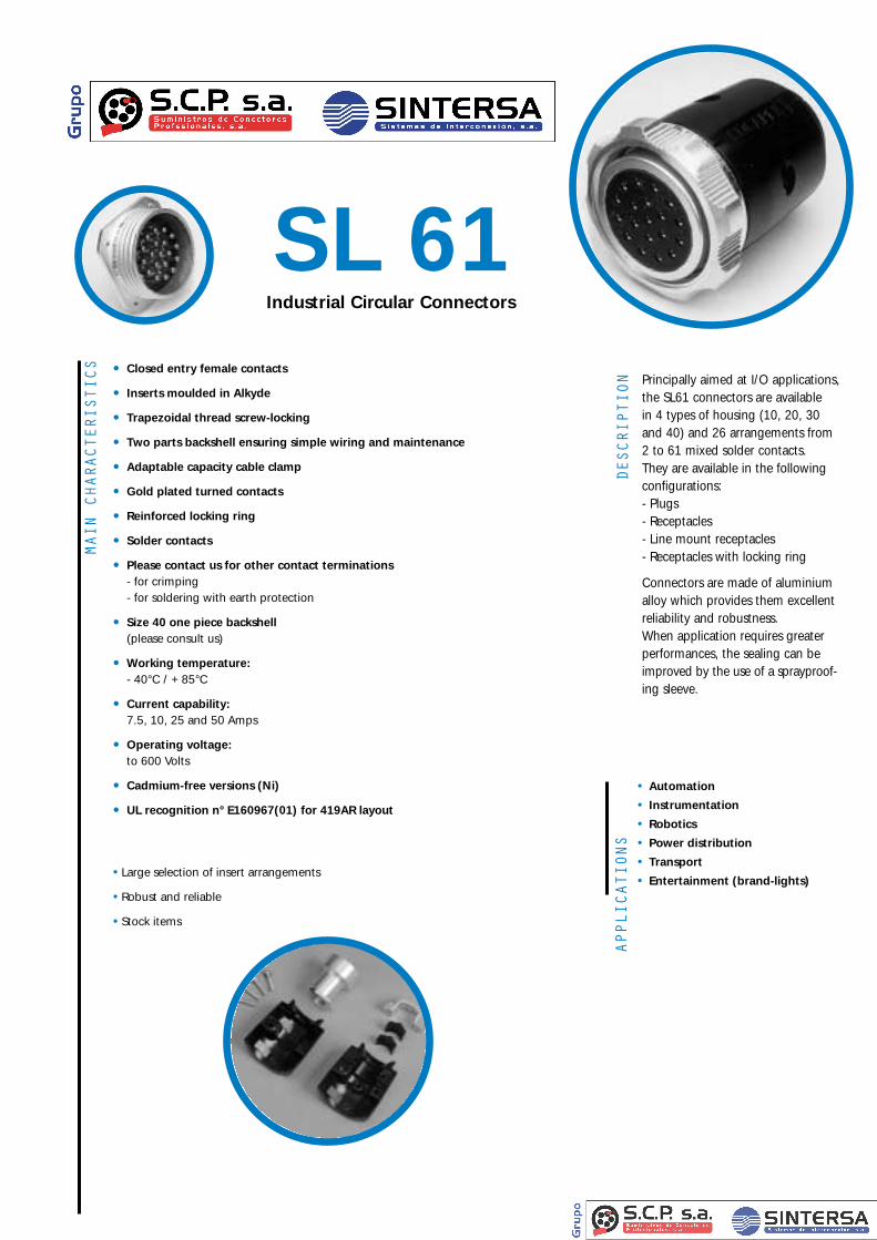
Contact arrangementsCHARACTERISTICS
Nominal current Contact resistanceMaximum permissible
wire dia.
7,5 A ≤ 5 m Ω 0.75 mm2
10 A ≤ 2 m Ω 1.75 mm2
25 A ≤ 2 m Ω 5.1 mm2
50 A ≤ 2 m Ω 13 mm2
Contact arrangement
Working voltage
Test voltage at sea level
+
❶
❷
❸
REMARK: the second and the third digit of the contact arrangements (if the third exists) indicate the number of contacts in the arrangement.Ex. : 426P = 26 contacts.
Accessories
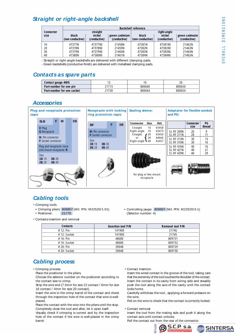
Straight or right-angle backshell
- Straight or right-angle backshells are delivered with different clamping pads.- Green backshells (conductive finish) are delivered with metallised clamping pads.
(Vrms)(Vrms)
❶❷❸
(Vrms)(Vrms)
❶❷❸
(Vrms)(Vrms)
❶❷❸
10 47377N 47377NI 21458N 47381N 47381NI 21462N20 47378N 47378NI 21459N 47382N 47382NI 21463N30 47379N 47379NI 21460N 47383N 47383NI 21464N40 47380N 47380NI 21461N 47384N 47384NI 21465N
Backshell referenceConnector straight right-anglesize black nickel green cadmium black nickel green cadmuim
(non conductive) (conductive) (conductive) (non conductive) (conductive) (conductive)
Adaptator for flexible conduitand PG:
Sealing sleeve:Plug and receptacle protectioncaps:
Receptacle with lockingring protection caps:
Connector PGsize thread
SL RF 209N 20 9SL RF 211N 20 11SL RF 313N 30 13SL RF 316N 30 16SL RF 416N 40 16SL RF 421N 40 21SL RF 429N 40 29
Connector Size Ref.
Straight 10 43458Right-angle 10 43473
Straight 20 43456or 30 44666
Right-angle 40 43457
F 3BBF
Size1B: 10 3B: 302B: 20 4B: 40
M: Pin connectorF: Socket connector
F M 3BSLB
F: PlugE: Receptacle
Size1B: 10 3B: 302B: 20 4B: 40
M: Pin connectorF: Socket connector
Plug and receptacle: noneLine mount receptacle: R
for plug or line mount receptacle
Male Female Male receptacle Female receptacle Square flange receptacle receptacle with locking ring with locking ring of receptacle
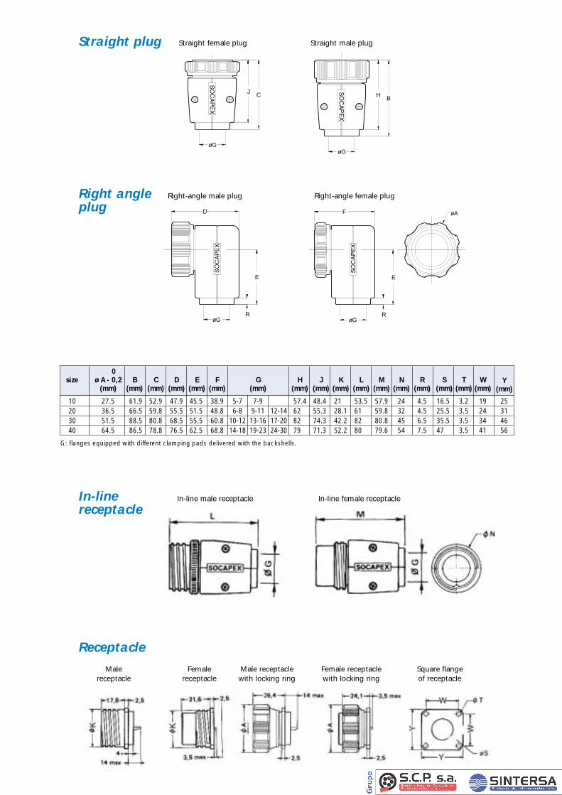
G: flanges equipped with different clamping pads delivered with the backshells.
10 27.5 61.9 52.9 47.9 45.5 38.9 5-7 7-9 57.4 48.4 21 53.5 57.9 24 4.5 16.5 3.2 1920 36.5 66.5 59.8 55.5 51.5 48.8 6-8 9-11 12-14 62 55.3 28.1 61 59.8 32 4.5 25.5 3.5 2430 51.5 88.5 80.8 68.5 55.5 60.8 10-12 13-16 17-20 82 74.3 42.2 82 80.8 45 6.5 35.5 3.5 3440 64.5 86.5 78.8 76.5 62.5 68.8 14-18 19-23 24-30 79 71.3 52.2 80 79.6 54 7.5 47 3.5 41
0size ø A - 0,2 B C D E F G H J K L M N R S T W
(mm) (mm) (mm) (mm) (mm) (mm) (mm) (mm) (mm) (mm) (mm) (mm) (mm) (mm) (mm) (mm) (mm)Y
(mm)
25314656
øG
D
E
R
øA
øG
F
E
R
øG
H B
øG
CJ
Right-angle male plug Right-angle female plug
In-line female receptacle
Straight male plugStraight female plugStraight plug
Right angleplug
In-linereceptacle
Receptacle
In-line male receptacle
HOW
TO O
RDER
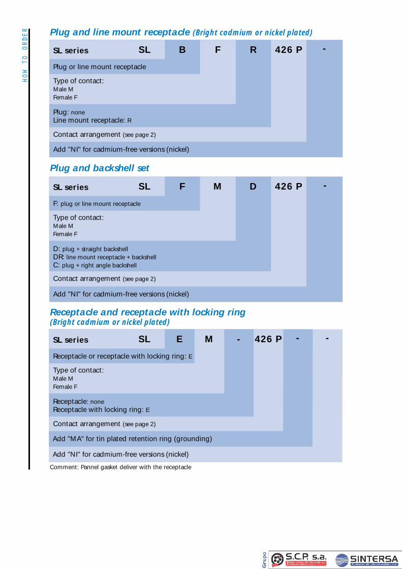
B F R 426 P
Plug or line mount receptacle
Type of contact:Male MFemale F
Plug: noneLine mount receptacle: R
Contact arrangement (see page 2)
Add "NI" for cadmium-free versions (nickel)
SL series SL -
F M D 426 P
F: plug or line mount receptacle
Type of contact:Male MFemale F
D: plug + straight backshellDR: line mount receptacle + backshellC: plug + right angle backshell
Contact arrangement (see page 2)
Add "NI" for cadmium-free versions (nickel)
SL series SL -
Plug and line mount receptacle (Bright cadmium or nickel plated)
Plug and backshell set
E M - 426 P
Receptacle or receptacle with locking ring: E
Type of contact:Male MFemale F
Receptacle: noneReceptacle with locking ring: E
Contact arrangement (see page 2)
Add "MA" for tin plated retention ring (grounding)
Add "NI" for cadmium-free versions (nickel)
SL series SL --
Receptacle and receptacle with locking ring (Bright cadmium or nickel plated)
Comment: Pannel gasket deliver with the receptacle
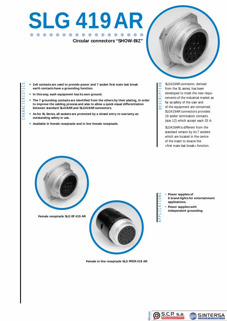
DESCRIPTION SLG419AR connector, derived
from the SL series, has beendeveloped to meet the new requi-rements of the industrial market asfar as safety of the user and of the equipment are concerned.SLG419AR connectors provides 19 solder termination contacts (size 12) which accept each 25 A.
SLG419AR is different from thestandard version by its 7 socketswhich are located in the centre of the insert to ensure the « first mate last break» fonction.
CHARACTERISTICS • 2x6 contacts are used to provide power and 7 socket first mate last break
earth contacts have a grounding function.
• In this way, each equipment has its own ground.
• The 7 grounding contacts are identified from the others by their plating, in order to improve the cabling process and also to allow a quick visual differentiationbetween standard SL419AR and SLG419AR connectors.
• As for SL Series, all sockets are protected by a closed entry to warranty an outstanding safety in use.
• Available in female receptacle and in line female receptacle.
APPLICATIONS • Power supplies of
6 brand-lights for entertainment applications.
• Power supplies with independent grounding.
Circular connectors “SHOW-BIZ”
SLG 419AR
Female receptacle SLG EF 419 AR
Female in line receptacle SLG FFDR 419 AR
Mechanical characteristics
• Aluminium alloy molded shells
• Mating by screwing system
• Alkydes inserts
• Gold plated copper alloy machined contacts (gold plated on nickel underplate for power contacts, electro-litic nickel plated for grounded contacts)
• Closed entry female contacts
• Reinforced mating screw
• Temperature range : -40°C to 85°C
Electrical characteristics
• Contact gauge AWG : 12
• Nominal current: 25 A
• Contact resistance < 0.002 Ohm
• Solder pot internal diameter: 2.5 mm
Contact arrangement electrical characteristics
• Test voltage at sea level: 1750 Vrms
• Working voltage in accordance with NF C 20-040, environmental conditions II : 400 Vrms
• Conform to new USITT’s specifications (American governmental agency)
AccessoriesPlease consult the standard SL data-sheet.
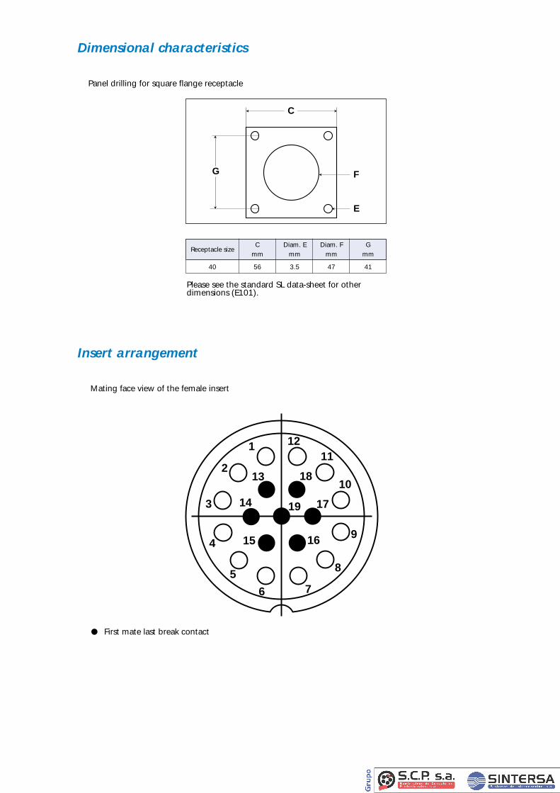
Dimensional characteristics
Panel drilling for square flange receptacle
Please see the standard SL data-sheet for other dimensions (E101).
C Diam. E Diam. F GReceptacle size
mm mm mm mm
40 56 3.5 47 41
G F
E
C
Insert arrangement
Mating face view of the female insert
12
17
1615
14
13
11
10
9
8
76
5
4
3
2
1
18
19
• First mate last break contact
HOW
TO O
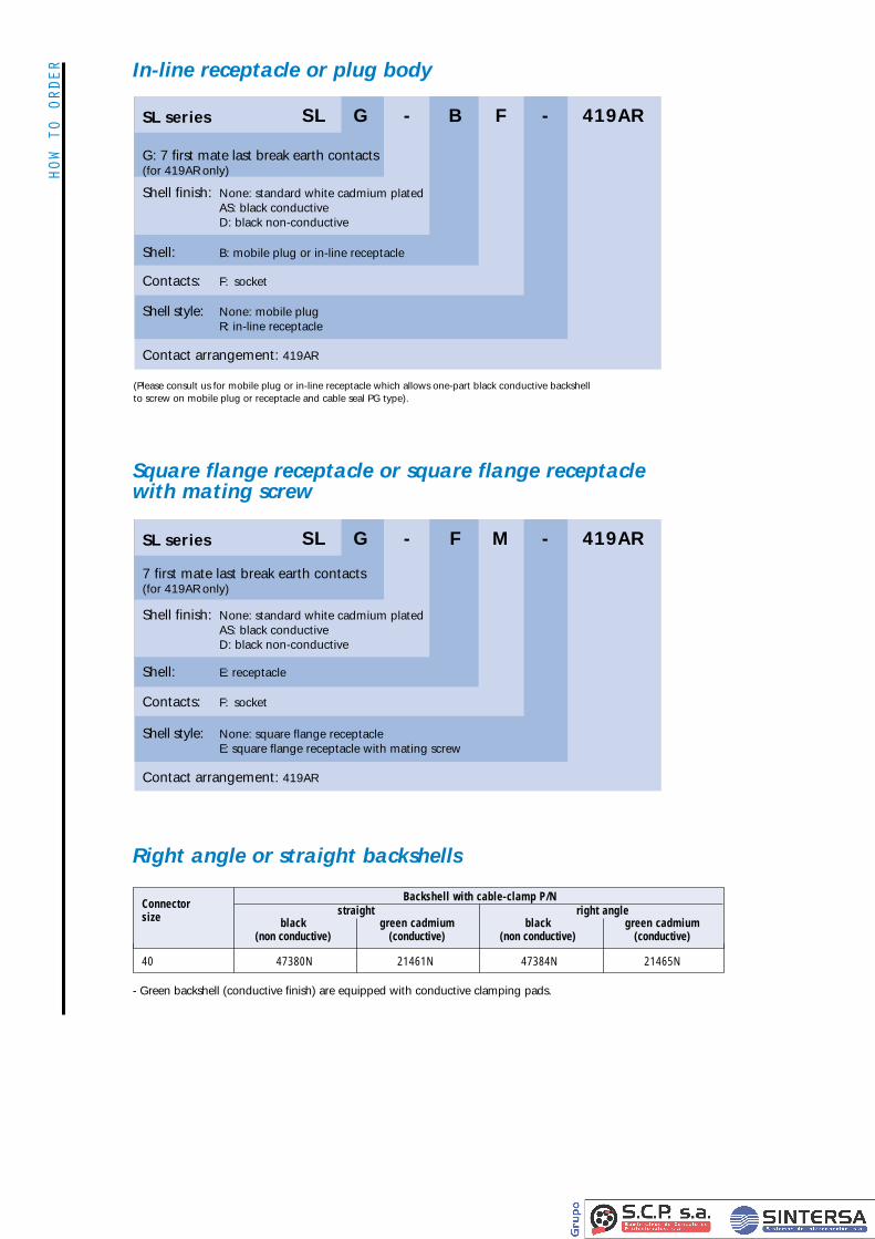
RDER In-line receptacle or plug body
40 47380N 21461N 47384N 21465N
Backshell with cable-clamp P/NConnector straight right anglesize black green cadmium black green cadmium
(non conductive) (conductive) (non conductive) (conductive)
- Green backshell (conductive finish) are equipped with conductive clamping pads.
(Please consult us for mobile plug or in-line receptacle which allows one-part black conductive backshell to screw on mobile plug or receptacle and cable seal PG type).
- B F - 419ARG
G: 7 first mate last break earth contacts(for 419AR only)
Shell: B: mobile plug or in-line receptacle
Contacts: F: socket
Shell style: None: mobile plugR: in-line receptacle
Contact arrangement: 419AR
Shell finish: None: standard white cadmium platedAS: black conductiveD: black non-conductive
SL series SL
- F M - 419ARG
7 first mate last break earth contacts(for 419AR only)
Shell: E: receptacle
Contacts: F: socket
Shell style: None: square flange receptacleE: square flange receptacle with mating screw
Contact arrangement: 419AR
Shell finish: None: standard white cadmium platedAS: black conductiveD: black non-conductive
SL series SL
Square flange receptacle or square flange receptacle with mating screw
Right angle or straight backshells
DESCRIPTION
APPLICATIONS
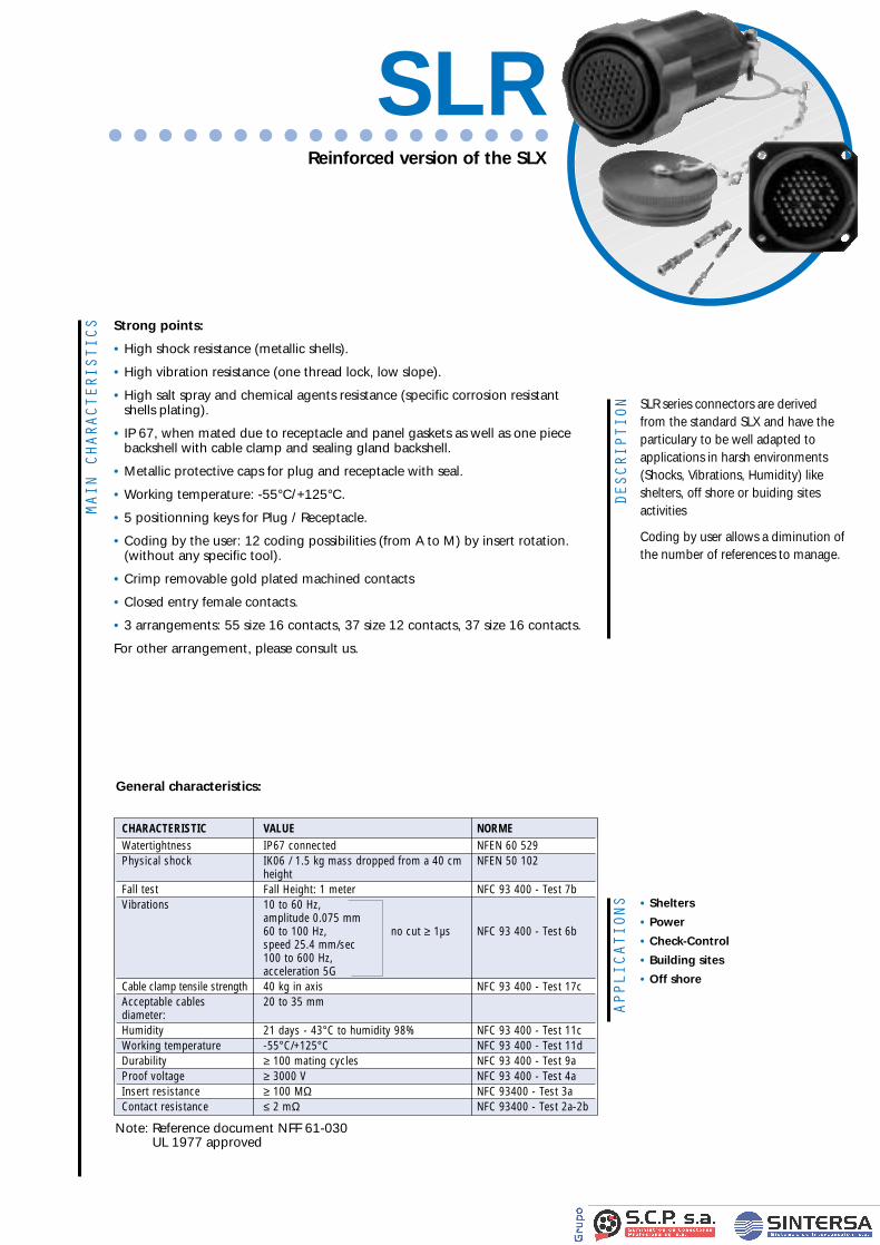
SLR series connectors are derived from the standard SLX and have theparticulary to be well adapted to applications in harsh environments(Shocks, Vibrations, Humidity) likeshelters, off shore or buiding sites activities
Coding by user allows a diminution ofthe number of references to manage.
• Shelters
• Power
• Check-Control
• Building sites
• Off shore
MAIN C
HARACTERISTICS Strong points:
• High shock resistance (metallic shells).
• High vibration resistance (one thread lock, low slope).
• High salt spray and chemical agents resistance (specific corrosion resistant shells plating).
• IP 67, when mated due to receptacle and panel gaskets as well as one piecebackshell with cable clamp and sealing gland backshell.
• Metallic protective caps for plug and receptacle with seal.
• Working temperature: -55°C/+125°C.
• 5 positionning keys for Plug / Receptacle.
• Coding by the user: 12 coding possibilities (from A to M) by insert rotation. (without any specific tool).
• Crimp removable gold plated machined contacts
• Closed entry female contacts.
• 3 arrangements: 55 size 16 contacts, 37 size 12 contacts, 37 size 16 contacts.
For other arrangement, please consult us.
Reinforced version of the SLX
SLR
General characteristics:
CHARACTERISTIC VALUE NORMEWatertightness IP67 connected NFEN 60 529Physical shock IK06 / 1.5 kg mass dropped from a 40 cm NFEN 50 102
heightFall test Fall Height: 1 meter NFC 93 400 - Test 7bVibrations 10 to 60 Hz,
amplitude 0.075 mm 60 to 100 Hz, no cut ≥ 1µs NFC 93 400 - Test 6bspeed 25.4 mm/sec 100 to 600 Hz, acceleration 5G
Cable clamp tensile strength 40 kg in axis NFC 93 400 - Test 17cAcceptable cables 20 to 35 mmdiameter: Humidity 21 days - 43°C to humidity 98% NFC 93 400 - Test 11cWorking temperature -55°C/+125°C NFC 93 400 - Test 11dDurability ≥ 100 mating cycles NFC 93 400 - Test 9aProof voltage ≥ 3000 V NFC 93 400 - Test 4aInsert resistance ≥ 100 MΩ NFC 93400 - Test 3aContact resistance ≤ 2 mΩ NFC 93400 - Test 2a-2b
Note: Reference document NFF 61-030UL 1977 approved
fiche SLR VA 11/12/00 12:51 Page 2
TECHNICAL
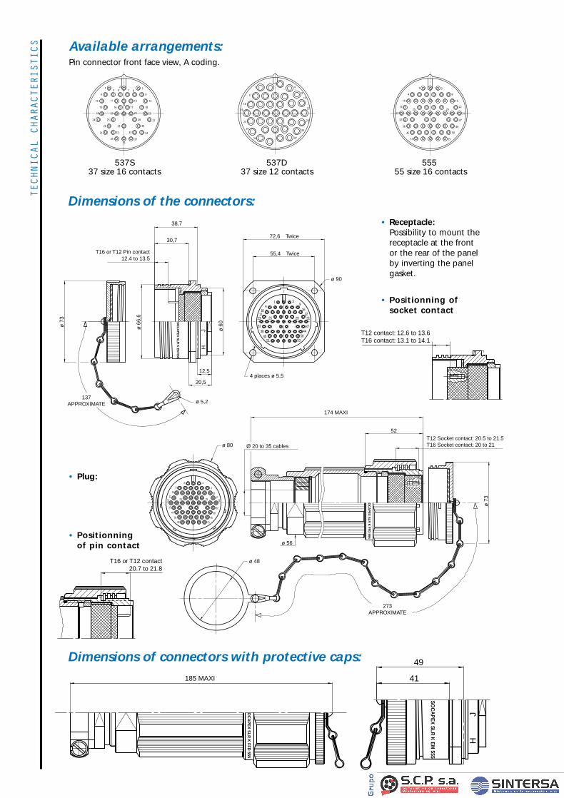
CHARACTERISTICS Available arrangements:
Pin connector front face view, A coding.
Dimensions of the connectors:
Dimensions of connectors with protective caps:
• Receptacle:Possibility to mount thereceptacle at the front or the rear of the panelby inverting the panelgasket.
• Plug:
38,7
72,6
ø 90
4 places ø 5,5
Twice
55,4 Twice
12,5
20,5
137APPROXIMATE
30,7
ø 6
0
HJ
ø 5,2
ø 6
6,6
ø 7
3
T16 or T12 Pin contact12.4 to 13.5
14
1017
23
39
1622
31
3744
505351
4538
25 29
32
SO
CA
PE
X S
LR K
EM
555
174 MAXI
52
ø 48
ø 80
ø 56
ø 7
3
Ø 20 to 35 cables
273APPROXIMATE
T12 Socket contact: 20.5 to 21.5T16 Socket contact: 20 to 21
1
4
1723
32
38
45
51
2529
3
9
16
2231
37
44
50
55
10
OC
AP
EX
SLR
K FFD
555
185 MAXI
OC
AP
EX
SLR
K FFD
555
49
JH
41
SO
CA
PE
X S
LR K
EM
555
537S37 size 16 contacts
537D37 size 12 contacts
55555 size 16 contacts
1
5
10
16
23
29
34 37
33
28
22
15
9
41
4
10
19
15
24
31
3535
37
34
27
23
18
14
9
387
265
11
16
20
25
28
13
17
22
26
30
3332
29
12
1
4
10
17
23
32
38
45
51
25
3
9
16
2229
31
37
50
55
44
• Positionning of socket contact
• Positionning of pin contact
T12 contact: 12.6 to 13.6T16 contact: 13.1 to 14.1
T16 or T12 contact 20.7 to 21.8
fiche SLR VA 11/12/00 12:51 Page 3
TECHNICAL
CHARACTERISTICSContacts:
Permissible wire:
Acceptable cable diameter:
Cabling process:
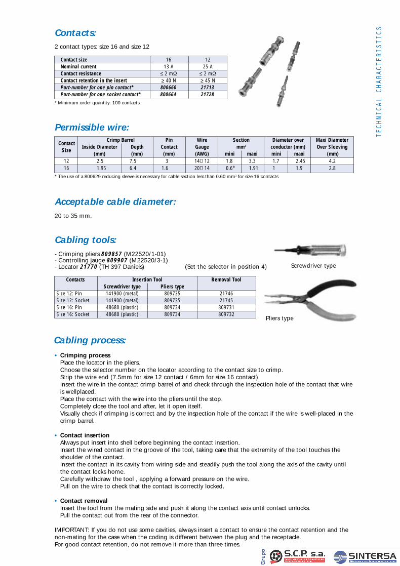
2 contact types: size 16 and size 12
* The use of a 800629 reducing sleeve is necessary for cable section less than 0.60 mm2 for size 16 contacts
* Minimum order quantity: 100 contacts
20 to 35 mm.
Cabling tools:- Crimping pliers 809857 (M22520/1-01)- Controlling jauge 809907 (M22520/3-1)- Locator 21770 (TH 397 Daniels)
Contact size 16 12Nominal current 13 A 25 AContact resistance ≤ 2 mΩ ≤ 2 mΩContact retention in the insert ≥ 40 N ≥ 45 NPart-number for one pin contact* 800660 21713Part-number for one socket contact* 800664 21728
ContactCrimp Barrel Pin Wire Section Diameter over Maxi Diameter
SizeInside Diameter Depth Contact Gauge mm2 conductor (mm) Over Sleeving
(mm) (mm) (mm) (AWG) mini maxi mini maxi (mm)12 2.5 7.5 3 14→12 1.8 3.3 1.7 2.45 4.216 1.95 6.4 1.6 20→14 0.6* 1.91 1 1.9 2.8
Contacts Insertion Tool Removal Tool Screwdriver type Pliers type
Size 12: Pin 141900 (metal) 809735 21746Size 12: Socket 141900 (metal) 809735 21745Size 16: Pin 48680 (plastic) 809734 809731Size 16: Socket 48680 (plastic) 809734 809732
• Crimping process Place the locator in the pliers.Choose the selector number on the locator according to the contact size to crimp.Strip the wire end (7.5mm for size 12 contact / 6mm for size 16 contact)Insert the wire in the contact crimp barrel of and check through the inspection hole of the contact that wireis wellplaced.Place the contact with the wire into the pliers until the stop.Completely close the tool and after, let it open itself.Visually check if crimping is correct and by the inspection hole of the contact if the wire is well-placed in thecrimp barrel.
• Contact insertionAlways put insert into shell before beginning the contact insertion.Insert the wired contact in the groove of the tool, taking care that the extremity of the tool touches theshoulder of the contact.Insert the contact in its cavity from wiring side and steadily push the tool along the axis of the cavity untilthe contact locks home.Carefully withdraw the tool , applying a forward pressure on the wire.Pull on the wire to check that the contact is correctly locked.
• Contact removalInsert the tool from the mating side and push it along the contact axis until contact unlocks.Pull the contact out from the rear of the connector.
IMPORTANT: If you do not use some cavities, always insert a contact to ensure the contact retention and thenon-mating for the case when the coding is different between the plug and the receptacle.For good contact retention, do not remove it more than three times.
Pliers type
Screwdriver type(Set the selector in position 4)
fiche SLR VA 11/12/00 12:51 Page 4
HOW
TO O
RDER How to order:
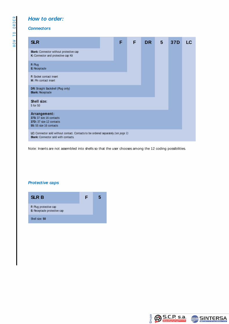
Connectors
Protective caps
LC: Connector sold without contact. Contacts to be ordered separately (see page 3)Blank: Connector sold with contacts.
Arrangement: 37S: 37 size 16 contacts37D: 37 size 12 contacts55: 55 size 16 contacts
Shell size: 5 for 50
DR: Straight Backshell (Plug only)Blank: Receptacle
F: Socket contact insert M: Pin contact insert
F: PlugE: Receptacle
Blank: Connector without protective capK: Connector and protective cap Kit
SLR F F DR 5 37D LC
Shell size: 50
F: Plug protective capE: Receptacle protective cap
SLR B F 5
Note: Inserts are not assembled into shells so that the user chooses among the 12 coding possibilities.
fiche SLR VA 11/12/00 12:51 Page 1
DESCRIPTION
APPLICATIONS
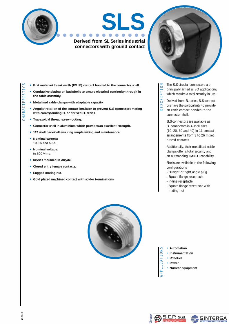
The SLS circular connectors areprincipally aimed at I/O applications,which require a total security in use.
Derived from SL series, SLS connect-ors have the particularity to providean earth contact bonded to theconnector shell.
SLS connectors are available as SL connectors in 4 shell sizes (10, 20, 30 and 40) in 11 contactarrangements from 3 to 26 mixedbrazed contacts.
Additionally, their metallised cableclamps offer a total security and an outstanding EMI/RFI capability.
Shells are available in the followingconfigurations : - Straight or right angle plug- Square flange receptacle- In-line receptacle- Square flange receptacle with
mating nut
• Automation
• Instrumentation
• Robotics
• Power
• Nuclear equipment
CHARACTERISTICS • First mate last break earth (FMLB) contact bonded to the connector shell.
• Conductive plating on backshells to ensure electrical continuity through in the cable assembly.
• Metallised cable clamps with adaptable capacity.
• Angular rotation of the contact insulator to prevent SLS connectors mating with corresponding SL or derived SL series.
• Trapezoidal thread screw-locking.
• Connector shell in aluminium which provides an excellent strength.
• 1/2 shell backshell ensuring simple wiring and maintenance.
• Nominal current: 10, 25 and 50 A.
• Nominal voltage: to 600 Vrms.
• Inserts moulded in Alkyde.
• Closed entry female contacts.
• Rugged mating nut.
• Gold plated machined contact with solder terminations.
E102
/B
Derived from SL Series industrial connectors with ground contact
SLS
Fiche SLS VA 11/12/00 14:04 Page 2
TECHNICAL
CHARACTERISTICS
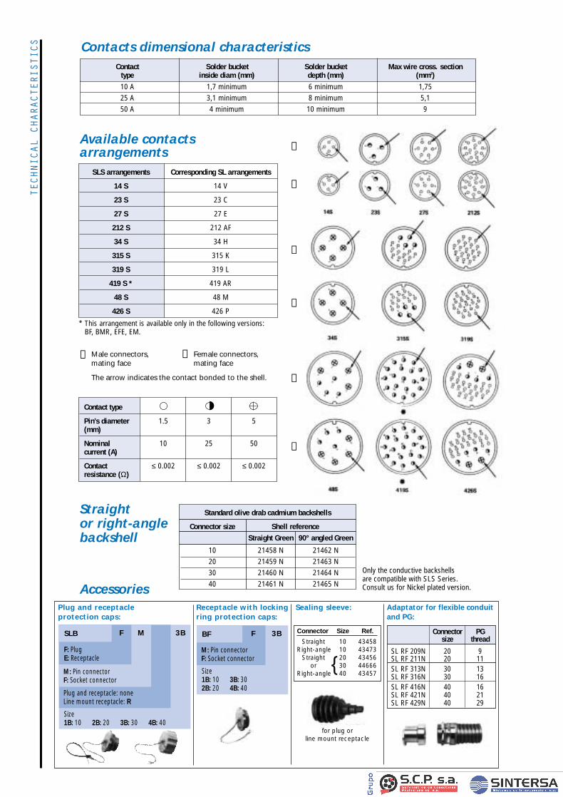
10 A 1,7 minimum 6 minimum 1,7525 A 3,1 minimum 8 minimum 5,150 A 4 minimum 10 minimum 9
Contact Solder bucket Solder bucket Max wire cross. sectiontype inside diam (mm) depth (mm) (mm2)
❶
❷
❶
❷
❶
❷
SLS arrangements Corresponding SL arrangements
14 S 14 V
23 S 23 C
27 S 27 E
212 S 212 AF
34 S 34 H
315 S 315 K
319 S 319 L
419 S * 419 AR
48 S 48 M
426 S 426 P
Male connectors, mating face
The arrow indicates the contact bonded to the shell.
Female connectors, mating face
❶ ❷
Available contactsarrangements
* This arrangement is available only in the following versions: BF, BMR, EFE, EM.
Contacts dimensional characteristics
Adaptator for flexible conduitand PG:
Sealing sleeve:Plug and receptacle protection caps:
Receptacle with lockingring protection caps:
F 3BBF
Size1B: 10 3B: 302B: 20 4B: 40
M: Pin connectorF: Socket connector
F M 3BSLB
F: PlugE: Receptacle
Size1B: 10 2B: 20 3B: 30 4B: 40
M: Pin connectorF: Socket connector
Plug and receptacle: noneLine mount receptacle: R
Accessories
Straight or right-anglebackshell
for plug or line mount receptacle
Standard olive drab cadmium backshells
Connector size Shell referenceStraight Green 90° angled Green
10 21458 N 21462 N20 21459 N 21463 N30 21460 N 21464 N40 21461 N 21465 N
Only the conductive backshells are compatible with SLS Series. Consult us for Nickel plated version.
Contact type
Pin’s diameter 1.5 3 5(mm)
Nominal 10 25 50current (A)
Contact ≤ 0.002 ≤ 0.002 ≤ 0.002resistance (Ω)
Connector PGsize thread
SL RF 209N 20 9SL RF 211N 20 11SL RF 313N 30 13SL RF 316N 30 16SL RF 416N 40 16SL RF 421N 40 21SL RF 429N 40 29
Connector Size Ref.
Straight 10 43458Right-angle 10 43473
Straight 20 43456or 30 44666
Right-angle 40 43457
Fiche SLS VA 11/12/00 14:04 Page 3
OVERALL
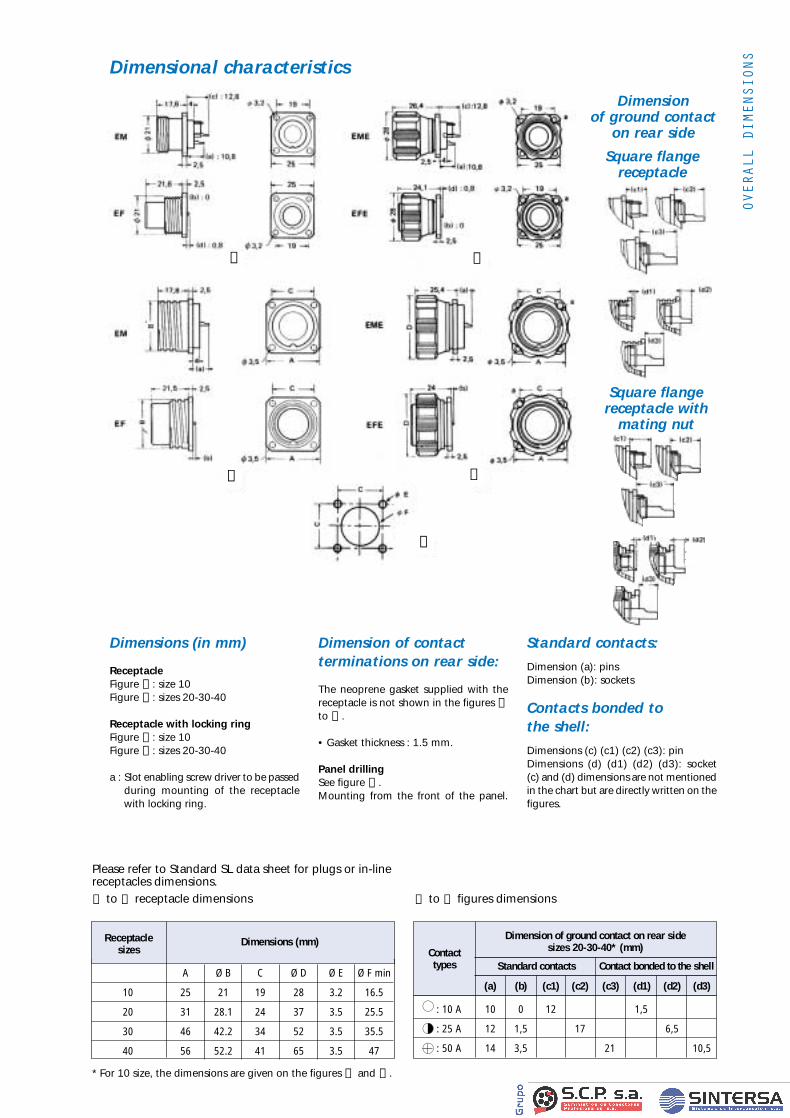
DIMENSIONSDimensional characteristics
A Ø B C Ø D Ø E Ø F min
10 25 21 19 28 3.2 16.5
20 31 28.1 24 37 3.5 25.5
30 46 42.2 34 52 3.5 35.5
40 56 52.2 41 65 3.5 47
Receptacle sizes
Dimensions (mm)
: 10 A 10 0 12 1,5
: 25 A 12 1,5 17 6,5
: 50 A 14 3,5 21 10,5
Dimension of ground contact on rear side
Contact sizes 20-30-40* (mm)
types Standard contacts Contact bonded to the shell
(a) (b) (c1) (c2) (c3) (d1) (d2) (d3)
Please refer to Standard SL data sheet for plugs or in-linereceptacles dimensions.
❶ to ❺ receptacle dimensions
* For 10 size, the dimensions are given on the figures ❶ and ❸ .
❶ to ❺ figures dimensions
Dimension of ground contact
on rear side
Dimensions (in mm)
ReceptacleFigure ❶ : size 10Figure ❷ : sizes 20-30-40
Receptacle with locking ringFigure ❸ : size 10Figure ❹ : sizes 20-30-40
a : Slot enabling screw driver to be passedduring mounting of the receptaclewith locking ring.
Dimension of contact terminations on rear side:
The neoprene gasket supplied with the receptacle is not shown in the figures ❶to ❹ .
• Gasket thickness : 1.5 mm.
Panel drillingSee figure ❺ .Mounting from the front of the panel.
Standard contacts:
Dimension (a): pinsDimension (b): sockets
Contacts bonded to the shell:
Dimensions (c) (c1) (c2) (c3): pinDimensions (d) (d1) (d2) (d3): socket(c) and (d) dimensions are not mentionedin the chart but are directly written on thefigures.
❶
❷
❸
❹
❺
Square flangereceptacle
Square flangereceptacle with
mating nut
Fiche SLS VA 11/12/00 14:04 Page 4
HOW
TO O
RDER
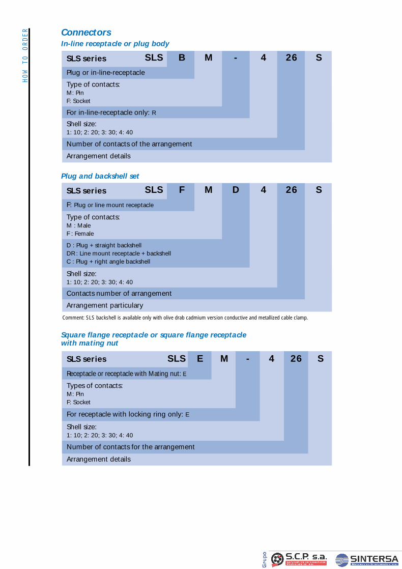
In-line receptacle or plug body
Plug and backshell set
Connectors
Square flange receptacle or square flange receptaclewith mating nut
SLS series
Type of contacts: M: Pin F: Socket
For in-line-receptacle only: R
Shell size: 1: 10; 2: 20; 3: 30; 4: 40
Number of contacts of the arrangement
Arrangement details
SLS B M - 4 26 S
Plug or in-line-receptacle
SLS series
Type of contacts: M : Male F : Female
D : Plug + straight backshellDR : Line mount receptacle + backshellC : Plug + right angle backshell
Shell size: 1: 10; 2: 20; 3: 30; 4: 40
Contacts number of arrangement
Arrangement particulary
SLS F M D 4 26 S
F: Plug or line mount receptacle
SLS E M - 4 26 SSLS series
Types of contacts: M: Pin F: Socket
For receptacle with locking ring only: E
Shell size: 1: 10; 2: 20; 3: 30; 4: 40
Number of contacts for the arrangement
Arrangement details
Receptacle or receptacle with Mating nut: E
Comment: SLS backshell is available only with olive drab cadmium version conductive and metallized cable clamp.
Fiche SLS VA 11/12/00 14:04 Page 1
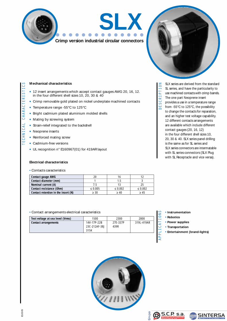
DESCRIPTION
APPLICATIONS • Instrumentation
•Robotics
•Power supplies
•Transportation
•Entertainment (brand-lights)
TECHNICAL
CHARACTERISTICS Mechanical characteristics
• 12 insert arrangements which accept contact gauges AWG 20, 16, 12. in the four different shell sizes 10, 20, 30 & 40
• Crimp removable gold plated on nickel underplate machined contacts
• Temperature range -55°C to 125°C
• Bright cadmium plated aluminium molded shells
• Mating by screwing system
• Strain-relief integrated to the backshell
• Neoprene inserts
• Reinforced mating screw
• Cadmium-free versions
• UL recognition n° E160967(01) for 419AR layout
Electrical characteristics
•Contacts caracteristics
Contact gauge AWG 20 16 12Contact diameter (mm) 1 1.5 3Nominal current (A) 7.5 13 25Contact resistance (Ohm) ≤ 0.005 ≤ 0.002 ≤ 0.002Contact retention in the insert (N) ≥ 30 ≥ 40 ≥ 45
E103
/B
Crimp version industrial circular connectors
SLX
•Contact arrangements electrical caracteristics
Test voltage at sea level (Vrms) 1500 2300 2800Contact arrangements 14V-17P-22B 27E-337P 319L-419AR
23C-212AF-38J 439R315K
SLX series are derived from the standardSL series, and have the particularity touse machined contacts with crimp barrels. The one part Neoprene insert provides a use in a temperature rangefrom -55°C to 125°C, the possibility to change the contacts for reparation,and an higher test voltage capability. 12 different contacts arrangements are available which include differentcontact gauges (20, 16, 12) in the four different shell sizes 10, 20, 30 & 40. SLX series panel drilling is the same as for SL series and SLX series connectors are intermatablewith SL series connectors (SLX Plug with SL Receptacle and vice versa).
NEW
Fiche SLX VA 11/12/00 12:57 Page 2
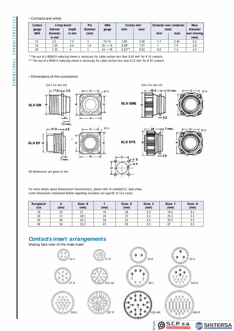
DIMENSIONAL
CHARACTERISTICS •Contacts and wires
Contact Crimp barrel Pin AWG Section mm2 Diameter over conductor Maxigauge Internal Depth diameter gauge mini maxi (mm) diameterAWG diameter in mm (mm) mini maxi over sleeving
in mm (mm)12 2.5 7.5 3 14-12 1.80 3.30 1.7 2.45 4.216 1.95 6.4 1.6 20 -> 14 0.60* 1.91 1 1.9 2.820 1.35 4 1 24 -> 18 0.22** 0.93 0.6 1.3 2.4
* The use of a 800629 reducing sleeve is necessary for cable section less than 0.60 mm2 for # 16 contacts** The use of a 800612 reducing sleeve is necessary for cable section less than 0.22 mm2 for # 20 contacts
•Dimensions of the connectors
For more details about dimensional characteristics, please refer to standard SL data-sheet. Some dimensions mentioned bellow regarding insulators are specific to SLX series.
Receptacle A Diam. B C Diam. D Diam. E Diam. F Diam. Hsize (mm) (mm) (mm) (mm) (mm) (mm) (mm)10 25 21 19 28 3.2 16.5 3.220 31 28.1 24 37 3.5 25.5 3.530 46 42.2 34 52 3.5 35.5 3.540 56 52.2 41 65 3.5 47 3.5
Ø H
Ø H
Ø H
Ø H
(15,1 for size 10) (24,1 for size 10)
14 V 17 P 22 B 23 C
27 E 212 AF 38 J
319 L 337 P 419 AR 439 R
315 K
All dimensions are given in mm
Contacts insert arrangements Mating face view of the male insert
Fiche SLX VA 11/12/00 12:57 Page 3
OVERALL
DIMENSIONS
Contacts as spare partsContact gauge AWG 12 16 20Part-number for one pin 21713 800660 800650Part-number for one socket 21728 800664 800654
Cabling tools
•Contacts insertion and removal
Cabling process•Crimping process
Place the positioner in the pliers.Choose the selector number on the positioner according tothe contact size to crimp.Strip the wire end (7.5mm for size 12 contact / 6mm for size16 contact / 4mm for size 20 contact).Insert the wire in the crimp barrel of the contact and checkthrough the inspection hole of the contact that wire is well-placed.Place the contact with the wire into the pliers until the stop.Completely close the tool and after, let it open itself.Visually check if crimping is correct and by the inspection hole of the contact if the wire is well-placed in the crimp barrel.
•Contact insertionInsert the wired contact in the groove of the tool, taking carethat the extremity of the tool touches the shoulder of the contact.Insert the contact in its cavity from wiring side and steadily push the tool along the axis of the cavity until the contactlocks home.Carefully withdraw the tool , applying a forward pressure onthe wire.Pull on the wire to check that the contact is correctly locked.
•Contact removalInsert the tool from the mating side and push it along thecontact axis until contact unlocks.Pull the contact out from the rear of the connector.
Contacts Insertion tool P/N Removal tool P/N# 12: Pin 141900 21746# 12: Socket 141900 21745# 16: Pin 48680 809731# 16: Socket 48680 809732# 20: Pin 39048 809729# 20: Socket 39048 809730
Straight or right-angle backshell
- Straight or right-angle backshells are delivered with different clamping pads.- Green backshells (conductive finish) are delivered with metallised clamping pads.
Accessories
•Crimping tools • Crimping pliers: 809857 (Mil. P/N: M22520/1-01)• Positioner: 21770
• Controlling jauge: 809907 (Mil. P/N: M22520/3-1)(Selector number: 4)
10 47377N 47377NI 21458N 47381N 47381NI 21462N20 47378N 47378NI 21459N 47382N 47382NI 21463N30 47379N 47379NI 21460N 47383N 47383NI 21464N40 47380N 47380NI 21461N 47384N 47384NI 21465N
Backshell referenceConnector straight right-anglesize black nickel green cadmium black nickel green cadmuim
(non conductive) (conductive) (conductive) (non conductive) (conductive) (conductive)
Adaptator for flexible conduitand PG:
Sealing sleeve:Plug and receptacle protectioncaps:
Receptacle with lockingring protection caps:
Connector PGsize thread
SL RF 209N 20 9SL RF 211N 20 11SL RF 313N 30 13SL RF 316N 30 16SL RF 416N 40 16SL RF 421N 40 21SL RF 429N 40 29
Connector Size Ref.
Straight 10 43458Right-angle 10 43473
Straight 20 43456or 30 44666
Right-angle 40 43457
F 3BBF
Size1B: 10 3B: 302B: 20 4B: 40
M: Pin connectorF: Socket connector
F M 3BSLB
F: PlugE: Receptacle
Size1B: 10 3B: 302B: 20 4B: 40
M: Pin connectorF: Socket connector
Plug and receptacle: noneLine mount receptacle: R
for plug or line mount receptacle
Fiche SLX VA 11/12/00 12:57 Page 4
HOW
TO O
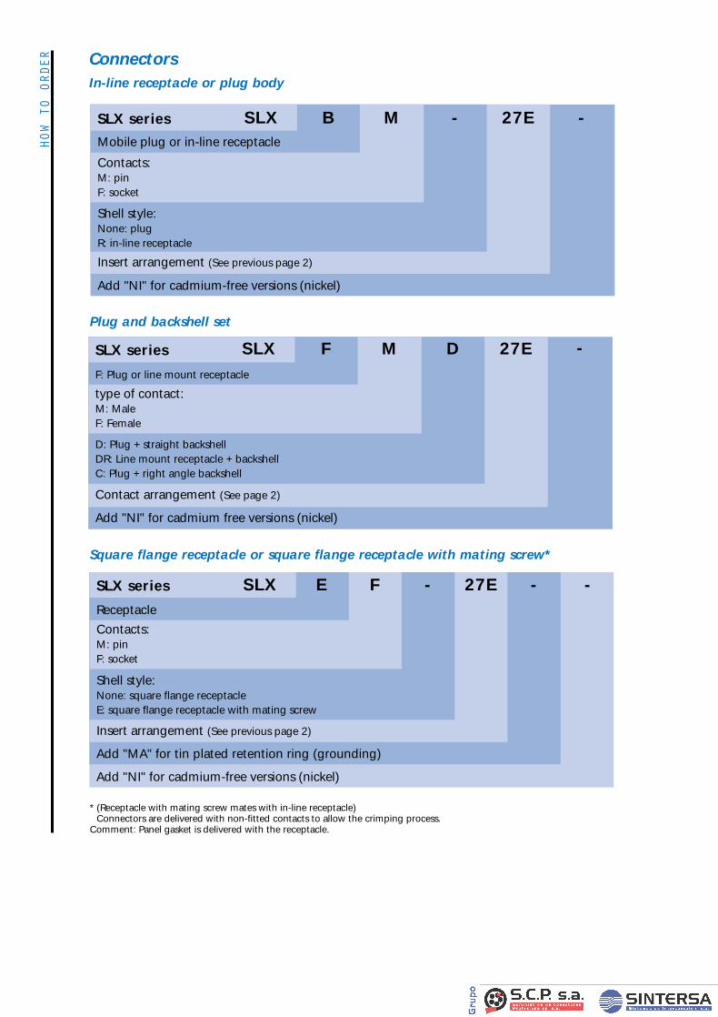
RDER Connectors
In-line receptacle or plug body
Square flange receptacle or square flange receptacle with mating screw*
* (Receptacle with mating screw mates with in-line receptacle)Connectors are delivered with non-fitted contacts to allow the crimping process.
Comment: Panel gasket is delivered with the receptacle.
B M - -27EMobile plug or in-line receptacle
Contacts:M: pinF: socket
Shell style:None: plugR: in-line receptacle
Insert arrangement (See previous page 2)
Add "NI" for cadmium-free versions (nickel)
SLX series SLX
E F - - -27EReceptacle
Contacts:M: pinF: socket
Shell style:None: square flange receptacleE: square flange receptacle with mating screw
Insert arrangement (See previous page 2)
Add "MA" for tin plated retention ring (grounding)
Add "NI" for cadmium-free versions (nickel)
SLX series SLX
Plug and backshell set
F M D 27EF: Plug or line mount receptacle
type of contact:M: MaleF: Female
D: Plug + straight backshellDR: Line mount receptacle + backshellC: Plug + right angle backshell
Contact arrangement (See page 2)
Add "NI" for cadmium free versions (nickel)
SLX series SLX -
Fiche SLX VA 11/12/00 12:57 Page 1


![Sl No. DISTRICTS Taluk Name WSD FPD SHOP NAME … FPD Distance.pdfkfcsc badami [61-61-rural] maruti yuvaka mandala hullikeri inam 20 kfcsc badami [62-62-rural] youth association mumaraddikoppa](https://img.pdfslide.us/doc/110x75/5e2988d3d1c7b30bbe44f734/sl-no-districts-taluk-name-wsd-fpd-shop-name-fpd-kfcsc-badami-61-61-rural-maruti.jpg)