Embed Size (px)
Citation preview
-1-
INTRODUCTION1-1 BEFORE YOUR OPERATION 11-2 PRECAUTIONS 21-3 PARTS IDENTIFICATION 2PREPARATIONS2-1 ORDERING DETECTOR BATTERIES 22-2 CHECKING THE WIRELESS TRANSMITTER SIZE 2INSTALLATION3-1 SEPARATING 33-2 WALL MOUNTING 33-3 POLE MOUNTING 53-4 MOUNTING IN THE BEAM TOWER 63-5 MOUNTING EXAMPLE AT PARTICULAR CASE 63-6 WIRING 7SETTING4-1 FUNCTION 84-2 OPTICAL ALIGNMENT 94-3 OPTIONAL SETTINGS 10OPERATION CHECK5-1 LED INDICATION 105-2 OPERATION CHECK 10TROUBLESHOOTING6-1 TROUBLESHOOTING 11DIMENSIONS7-1 DIMENSIONS 11SPECIFICATIONS 8-1 SPECIFICATIONS 11OPTIONS9-1 OPTIONS 12
Warning
Caution
Warning
Caution
1
2
3
4
5
6
7
8
9
INSTALLATION INSTRUCTIONSNo. 59-1880-1
CONTENTS
FEATURES
Failure to follow the instructions provided with this indication and improper handling may cause death or serious injury.Failure to follow the instructions provided with this indication and improper handling may cause injury and/or property damage.
• Read this instruction manual carefully prior to installation.• After reading, store this manual carefully in an easily accessible place for reference.
• This manual uses the following warning indications for correct use of the product, harm to you or other people and damage to your assets, which are described below. Be sure to understand the description before reading the rest of this manual.
This symbol indicates prohibition. The specific prohibited action is provided in and/or around the figure.
This symbol requires an action or gives an instruction.
INTRODUCTION11-1 BEFORE YOUR OPERATION
Detection range 100m/350ft.
SL-350 QFR
SL-350 QNR
Detection range 100m/350ft. 4 selectable beam frequencies
• Battery-operated detector- Battery life: Transmitter Approx. 4 years (2 in the transmitter) Receiver Approx. 5 years (2 in the receiver) (when using LSH20 (3.6V, 13Ah) batteries manufactures by SAFT)- Up to 8 batteries (4 in the transmitter, 4 in the receiver) (normal operation requires 2 batteries)- Battery saving function- Intermittent output function- Spacious back bck box for numerous wireless transmitter
• Quad high power beams• Smart design
- Slim body design- Easy-to-see vivit interior color for optical alignment- IP65 waterproof structure
• 4 channel beam frequency selector (SL-350QFR only)• Viewfinder with 2X magnification• Beam interruption adjustment function• D.Q. circuit (environmental disqualification)• Tamper function• LED indicator for an easy alignment• Various options (refer to page 12)
( ABC-4, BC-4, BCU-4, PSC-4, SBU-4, BAU-4, EC-4 ) Do not use the product for purposes other than the detection of moving objects such as people and vehicles.Do not use the product to activate a shutter, etc., which may cause an accident.Do not touch the unit base or power terminals of the product with a wet hand (do not touch when the product is wet with rain, etc.). It may cause electric shock.
Never attempt to disassemble or repair the product. It may cause fire or damage to the devices.Do not use batteries that have different levels of power remaining (i.e., new and used batteries).Not observing the above may result in an explosion, leakage of electrolyte, emission of toxic gases or other outcomes that may be harmful to people and property.
[Handling of Batteries]Do not recharge, short circuit, crush, disassemble, exceed heat above 100°C (212°F), incinerate, or expose contents to water. Do not solder directly to the cell. Not observing the above may result in fire, explosion or severe burn hazard.
Do not solder directly to the cell.Do not pour water over the product with a bucket, hose, etc. The water may enter, which may cause damage to the devices.Clean and check the product periodically for safe use. If any problem is found, do not attempt to use the product as it is and have the product repaired by a professional engineer or electrician.
BATTERY OPERATED PHOTOELECTRIC DETECTOR
Smart Line series
BATTERY OPERATED PHOTOELECTRIC DETECTOR
Smart Line series™™
-2-
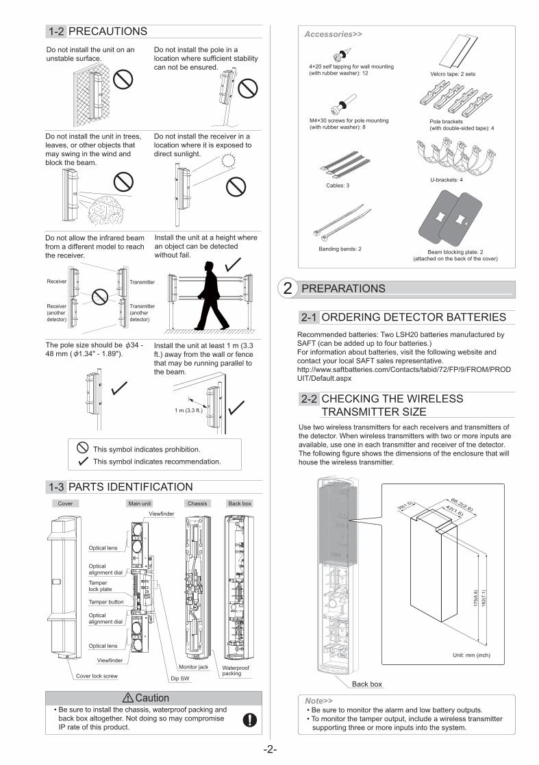
Use two wireless transmitters for each receivers and transmitters of the detector. When wireless transmitters with two or more inputs are available, use one in each transmitter and receiver of tne detector.The following figure shows the dimensions of the enclosure that will house the wireless transmitter.
Recommended batteries: Two LSH20 batteries manufactured by SAFT (can be added up to four batteries.)For information about batteries, visit the following website and contact your local SAFT sales representative.http://www.saftbatteries.com/Contacts/tabid/72/FP/9/FROM/PRODUIT/Default.aspx
• Be sure to monitor the alarm and low battery outputs.• To monitor the tamper output, include a wireless transmitter
supporting three or more inputs into the system.
Note>>
1-2 PRECAUTIONS
PREPARATIONS22-1 ORDERING DETECTOR BATTERIES
2-2 CHECKING THE WIRELESS TRANSMITTER SIZE
1-3 PARTS IDENTIFICATION
Do not install the unit on an unstable surface.
Do not install the pole in a location where sufficient stability can not be ensured.
Do not install the unit in trees, leaves, or other objects that may swing in the wind and block the beam.
Do not install the receiver in a location where it is exposed to direct sunlight.
Install the unit at a height where an object can be detected without fail.
The pole size should be 34 - 48 mm ( 1.34" - 1.89").
Do not allow the infrared beam from a different model to reach the receiver.
Install the unit at least 1 m (3.3 ft.) away from the wall or fence that may be running parallel to the beam.
Accessories>>
Velcro tape: 2 sets
U-brackets: 4
Pole brackets(with double-sided tape): 4
4×20 self tapping for wall mounting (with rubber washer): 12
M4×30 screws for pole mounting(with rubber washer): 8
Beam blocking plate: 2(attached on the back of the cover)
Cables: 3
Banding bands: 2
This symbol indicates prohibition.
This symbol indicates recommendation.
1 m (3.3 ft.)
Back box
Unit: mm (inch)
175(
6.8)
39(1.5)66.2(2.6)
42(1.6)
182(
7.1)
Chassis Back boxMain unitCover
Monitor jack
Dip SW
Viewfinder
Viewfinder
Optical alignment dial
Tamperlock plate
Tamper button
Optical alignment dial
Optical lens
Optical lens
WaterproofpackingCover lock screw
Caution• Be sure to install the chassis, waterproof packing and
back box altogether. Not doing so may compromise IP rate of this product.
Receiver
Transmitter (another detector)
Receiver (another detector)
Transmitter
-3-
Warning������� ;����� ��������=��� <<�������=����<�
��������� � �'�> ���������������������� ��������� ���<�� <<���������<�������?��
� ������= �'������=������������ ������;��� ������&�'��<������������� �� ��<�; ��'�������������������������������<���������������������
�����=��all����� ����� ��������� �'�� ������������<�� �� ����<������������������� �� ����@���� ���������������� ������� �&�
��$�#@@#����3
"�� �
3
4
"���������� ���J������������������� ������'������������
����������<������� ��� ��������&��;�
��������������� ��$#\��@$^+_`�{�J�|`�#�
J��������
"�� �
Note>>
`}+ ~#@@��������!
`}| $��#�#���!
| �� �'���������� =������ � �����������&����&��&���� ��>;{?� ��������&��;���������
| ���=������=���
3
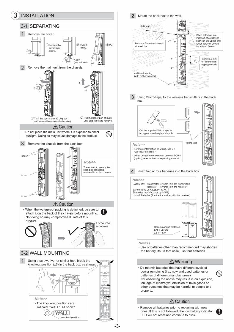
�� �' Velcro tape, < ;����� ������������ ���� ��������&��;�
Note>>
����3@��������=�����&�������
+ �� �� �� '����
|
����������������� ���� ������� � ���;������� �������� '���� �'�����������������'������������
Note>>
���&���� �
������&��&���� ����������&�����~#@@�����������
��\������ �<��� ����� � �'������`}���~����!������'����
��~������ �'������������������ ��"�}��>� �?����<��������������� �'��������
������<����� ������������������������������������������ <�������������������<������� ���
���=���������� ��<���������&��;�
+ ����������&��;����������
Note>>
+ ���=������� ���� �<����������� ��
������������������<��� ���� �������� ��� �����=��
+��������� ������ ��_���'������������������������>���� ���?�
|
Note>>������� <�* ������ ������������>+� ���������� ��?� ���� =����������������>+� ��������� =��?��������� �'�@$^+_>`�{J��|`#�?������ �������<����������$#\����������� ���>�� ���������� ������ ��������� =��?> >
|�
+� `�
��
����
����
����
�������������������������&��;������������=���<����������� ��
#�� �>�� �������?
��+_����<���� �'>� ���������������?
$ �������������������
� ������<������� �������*�������|�
�<�������������� ������������� �����������������������������������������������������+_���
"�� ���~�������������<����& �'� ��������������������
����� ���������&�<��������� ����<������ �'����� �'������������ ����������<�� ��������
\���� ����'�=�
� ��*��`�����\������� ���'��'������ ���;

-4-
Note>>
9 Close the cover.
8 Connect the cables and complete setting and alignment. (refer to page 8, 9)
Note>>
Run the cables so that they are not pinched between the chassis and back box.
5
6
Caution
Hook on the upper part of the chassis.
Push the lower part of the cover until it clicks into position.
1
2
Pass the cables through the wiring hole of the chassis and mount the chassis to the back box.
Fasten the cover lock screw.3
• For more information on wiring, see “WIRING” on page 7.
• Put the cables in order not to be caught between the main unit and cover.
• Push the middle part of the cover and hide this orange label completely when in operation.
• Do not contact with the optical unit when mounting the cover. Otherwise malfunction may occur due to the shift of the optical axis, resulting in the need of readjustment.
Banding band
Wiring notch
Pull
7 Fix the main unit on the chassis.
Insert the lower part, and then push the upper part onto the chassis.
1
Turn the optical unit 90 degrees and tighten the screws (both sides).
2
fasten
fasten
fasten
Caution• Avoid cables from being caught between chassis.• When the waterproof packing is detached, be sure to
attach it on the back of the chassis before mounting. Not doing so may compromise IP rate of this product.
Force into a groove
Caution• Tighten the screws
completely by torque of 1.0 - 1.5 N·m.Not doing so may cause malfunction of wall tamper.
Orange label
A co
ver m
ust h
ide
this
ora
nge
labe
l com
plet
ely
whe
n in
ope
ratio
n.
-5-
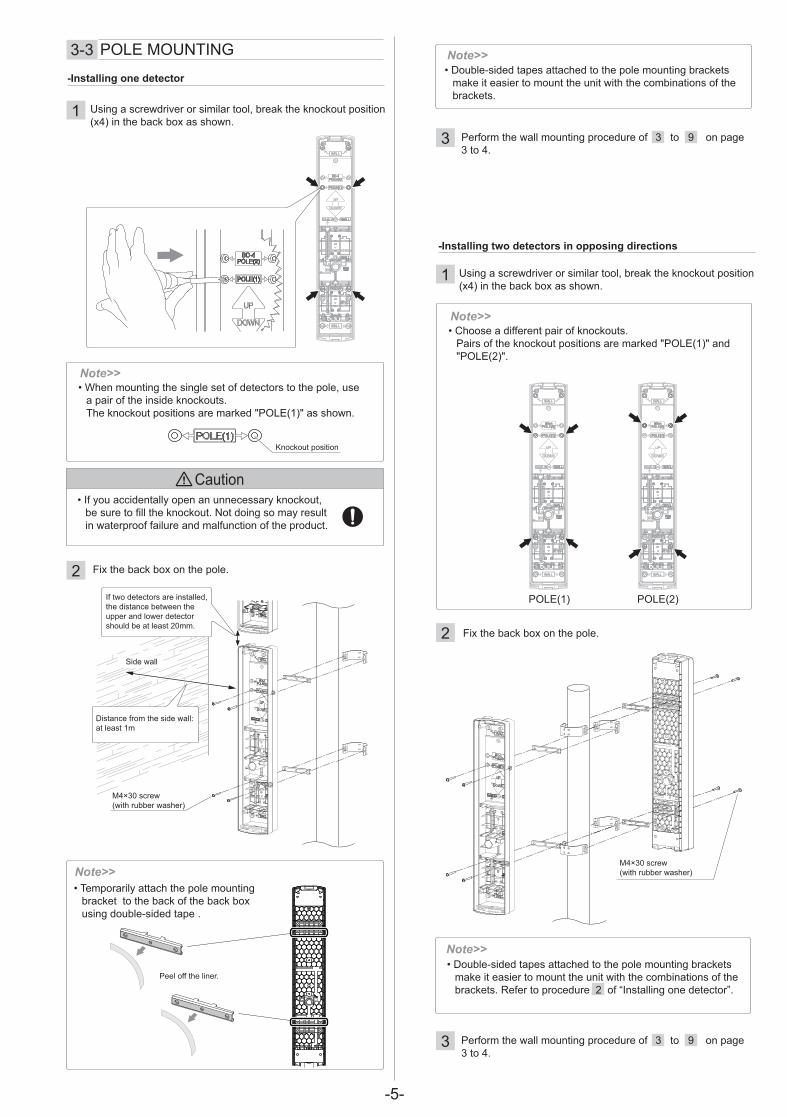
-Installing two detectors in opposing directions
1
2 Fix the back box on the pole.
Note>>
3-3 POLE MOUNTING
1
2 Fix the back box on the pole.
Note>>
-Installing one detector
Using a screwdriver or similar tool, break the knockout position (x4) in the back box as shown.
Note>>
Caution
Note>>��Temporarily attach the pole mounting
bracket to the back of the back box using double-sided tape .
Using a screwdriver or similar tool, break the knockout position (x4) in the back box as shown.
Note>>
M4×30 screw(with rubber washer)
��Double-sided tapes attached to the pole mounting brackets make it easier to mount the unit with the combinations of the brackets. Refer to procedure 2 of “Installing one detector”.
Knockout position
Peel off the liner.
3 Perform the wall mounting procedure of 3 to 9 on page 3 to 4.
3 Perform the wall mounting procedure of 3 to 9 on page 3 to 4.
POLE(1) POLE(2)
��When mounting the single set of detectors to the pole, use a pair of the inside knockouts.The knockout positions are marked "POLE(1)" as shown.
��If you accidentally open an unnecessary knockout, be sure to fill the knockout. Not doing so may result in waterproof failure and malfunction of the product.
��Double-sided tapes attached to the pole mounting brackets make it easier to mount the unit with the combinations of the brackets.
��"������� <<������� ��<�&��&���Pairs of the knockout positions are marked "POLE(1)" and "POLE(2)".
Side wall
M4×30 screw(with rubber washer)
Distance from the side wall:at least 1m
If two detectors are installed, the distance between the upper and lower detector should be at least 20mm.

-6-
Select a mounting pattern according to the tower to be used.
3-4 MOUNTING IN THE BEAM TOWER
- Mounting the detector
- Mounting the detector separate from the back box
Caution
2
• The switch selection is not recognized when locking the tamper button.
Release the tamper button before selecting a function using the switch.
• After completing the settings, be sure to lock the tamper button to check that all LEDs are OFF.
If the tamper button is not locked, the LEDs are kept ON, which consumes more battery power.
• The monitor jack output is disabled when the tamper button is locked.
• When locking the tamper button, the beam alignment test point will be disabled. Complete the alignment procedure before locking the tamper button.
1
Be sure to remove the waterproof packing.
2
1
Fix the back box and main unit.3
1 Avoid installing the transmitter and receiver facing each other through the corner of the cover.
2 In doing this installation, the maximum detection range shall be half of the original detection range. (This is to compensate the attenuation of beam by the corner of the cover.)
When installing the detector without the cover, lock the tamper button with the tamper lock plate on both the transmitter and receiver.
• When mounting the back box and the main unit, use extension cable with connector EC-4 (option).
Note>>
Extension cable with connector EC-4
Open the wiring guide on the back of the chassis using pliers as shown.
Up to150mm
Loosen the screw and rotate the tamper lock plate.
Fasten the screw to lock the tamper button.
1 2
• Remove two screws fixing the waterproof packing.
Note>>
3-5 MOUNTING EXAMPLE AT PARTICULAR CASE
ex) SL-200QN 60m/200ft. 30m/100ft.
Transmitter Receiver
[ Top view ]
Caution
Tamper position
Mounting pattern
Main unit Main unit+ Chassis
Main unit+ Chassis+ Back box
When using the tamper output, install the detector with the tamper shown above being pressed.Not doing so may cause malfunction of wall tamper.
Tamper position Tamper position Tamper position
Tamper lock plate
Tamper button

-7-
Input(N.C.)
Input(N.C.)
Input(N.C.)
Input(N.C.)
TransmitterThis product is provided with wiring based on the assumption that N.C. wireless transmitters are used.Connect the cables from the back box (Yellow/Yellow-white, Green/Green-white, and Black/Black-white) to the respective terminals on the wireless transmitters.
������ ������� '��������� ������������� ���������wireless transmitters with four inputs or use two wireless transmitters with two inputs each.
���<������ ������������������������ ������������ ������������������������������������������������$� ��������������������������<�����"�������
��~����������������������������������������� ����� �����������������������������������\��information about wiring, see the wiring diagram in “Setting the D.Q. output” in “4-3” on page 10.
���������������������������������������������&��;������ ������������ �������� �'������������������ ������������������ ��"�}��>� �?�
NOTE>>
3-6 ~����!
Receiver
���Black
Power input (+)Power input (-)
���Black
����'�BrownYellow~� �
GreenBluePurple!���
GreenBluePurple!���
@�����������@�����������Tamper outputTamper output
����'�BrownYellow~� �
DQ outputDQ outputAlarm outputAlarm output
Main unit Back box
���Black
Power input (+)Power input (-)
���Black
GreenBluePurple!���
GreenBluePurple!���
@�����������@�����������Tamper outputTamper output
Main unit Back box
+ –��~��
+ –��~��
NC"��NC
LB �#����
"��
+ –��~��
+ – NC "���� �� NC"��NC
��~�� #@#��DQ LB �#����
"��NC"��
Main unit
Main unit
Back box
~ ������������ ��
���
Bla
ck
Blu
e
Gre
en
Pur
ple
!��
�
���
Bla
ck
Blu
e
Gre
en
Pur
ple
!��
�
���
�'�
Bro
wn
~�
�
Yello
w
Back box
~ ������������ ��
�������<������� � �'�����������=�����wireless transmitters are required and one of them must have two outputs.
NOTE>>
Input(N.C.)
Input(N.C.)
~��� �'��~������ �'��"�}��>� �?�����������
���������"�}�������������� �����batteries into the wireless transmitter. � �'������������� ��< ������;��� ��
-8-
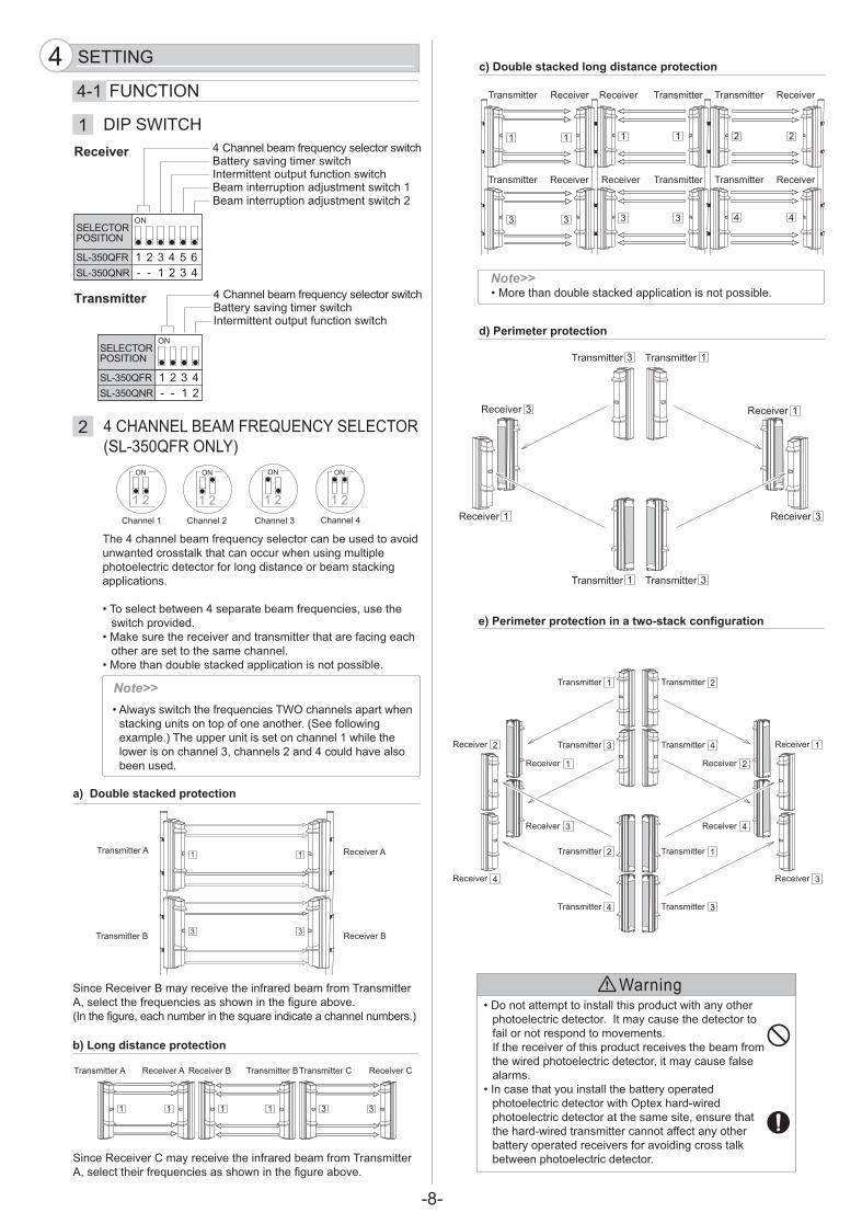
Warning
e) Perimeter protection in a two-stack configuration
Transmitter A
Transmitter B
Receiver A
Receiver B
1
3
1
3
1
3
1
3
1
3
1
3
2
4
2
4
��#�������� ������<������� ����~������������������������& �'��� ������<�����������>$���<��� �'��;������?������������� � ���������������|��� ����������� ������������`�����������+��������������=����������������
Note>>
������������ ������� ��������� ������������������ ��������������������������������<� ���������������=��������<�������� =���<�� ������������ =�����������<������� ����������� ��������� �����������<������������
���������������� ����������������������������� ��������� �����;�����}� ����������� ������������������� ��������������������}� ��������� ���������<<���������������������������� =����<���= � �'��������&��������������� ��������
$�����!44-1 \��"����
�������������������<������������������������������= ����������������&�������������������� �'���� ����������� ��������<����'�� ����������������& �'����� �� ���
��������������������������������<������� ������������� �����= ����
����&�������������� =������������ ����������<�� �'����������������������������������
�������������������&������� �� �� ������� ����
������
a) Double stacked protection
$ �������� =������������� =����� �<�����������<��������� ���#�����������<������� ����������� �����< '������=��>������< '����������������� ������������ �� ����������������������?
$ �������� =���"��������� =����� �<�����������<��������� ���#���������� ��<������� ����������� �����< '������=��
c) Double stacked long distance protection
�������������������&������� �� �� ������� ����Note>>
d) Perimeter protection
Transmitter 1Transmitter 3
Transmitter 1 Transmitter 3
Receiver 1
Receiver 1
Receiver 3
Receiver 3
Transmitter Receiver
Transmitter Receiver
Receiver Transmitter
Receiver Transmitter
Transmitter Receiver
Transmitter Receiver
"�������| "�������`"�������+ "��������
Receiver
��
1
2
����$~��"^
��"^#���@���#��\������"��$�@�"���>$@}`�_�\����@�?
$@}`�_�\�$@}`�_���
$�@�"�����$�����
4 "������������<������������������ ����������= �'� ������ ������� �������<��� ���� ������� ������ ������������� ���|����� ������ ������������� ���+
Transmitter
��
$@}`�_�\�$@}`�_���
$�@�"�����$�����
4 "������������<������������������ ����������= �'� ������ ������� �������<��� ���� ��
1 1 1 1 3 3
Transmitter A Receiver A Receiver B Transmitter B������ ���" ���� =���"
b) Long distance protection
��
Transmitter 3
Transmitter 1
Transmitter 4
Transmitter 2
Receiver 2
Receiver 4
Receiver 1
Receiver 3
Receiver 2
Receiver 4
Receiver 1
Receiver 3
Transmitter 4
Transmitter 2
Transmitter 3
Transmitter 1
-9-
10°10°
10°10°90° 90°
Horizontal alignment angle Vertical alignment angle
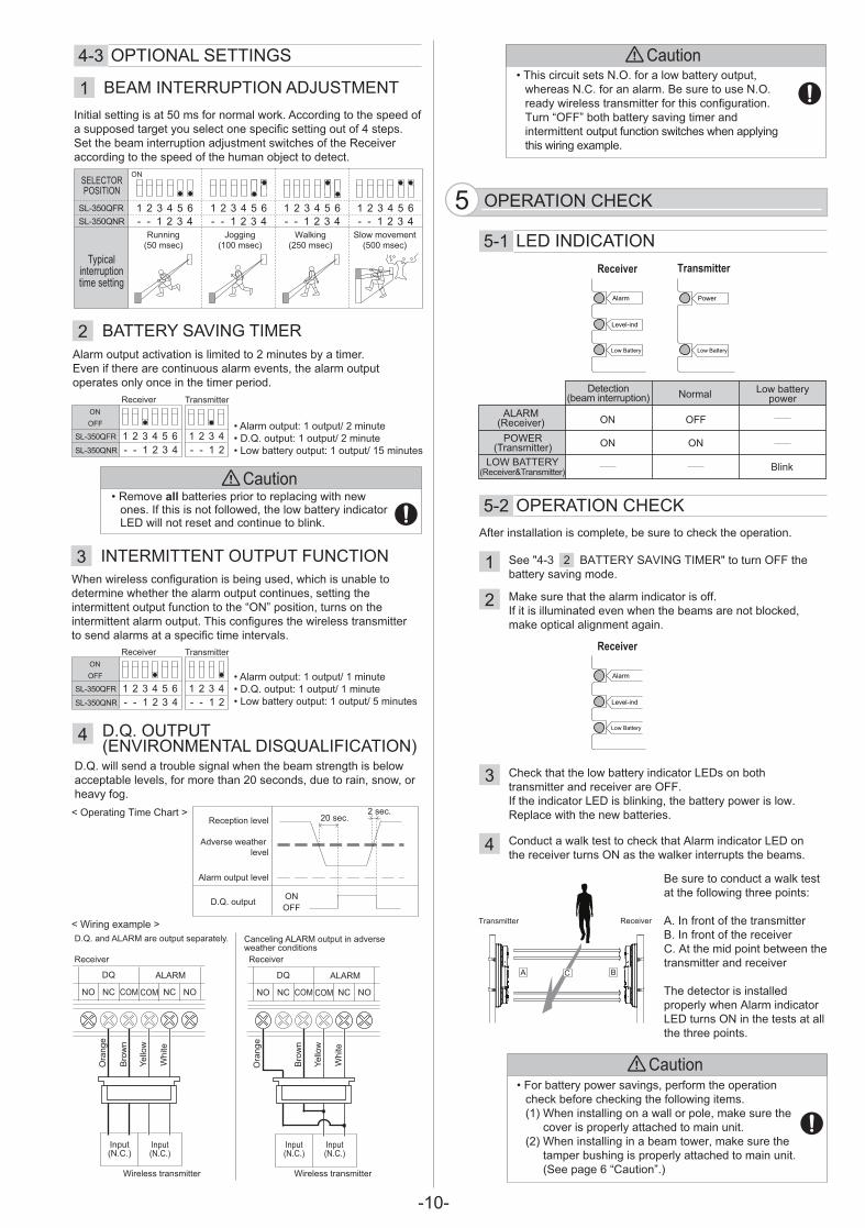
Caution
1
4
5
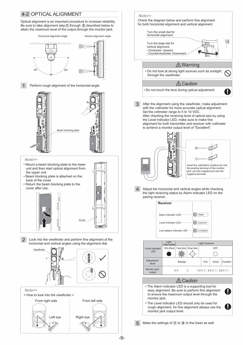
Optical alignment is an important procedure to increase reliability. Be sure to take alignment step 1 through 5 described below to attain the maximum level of the output through the monitor jack.
Level indicator LED
Light interrupted Light received
Adjustment level
Monitor jack output
Realign Fair Good Excellent
0 V 1.0 V 2.4 V 2.8 V
ON (Red) Fast blink Slow blink OFF
��The Alarm indicator LED is a supporting tool for easy alignment. Be sure to perform fine alignment to ensure the maximum output level through the monitor jack.
4-2 OPTICAL ALIGNMENT
3 After the alignment using the viewfinder, make adjustment with the voltmeter for more accurate optical alignment. Set the voltmeter range to 5 to 10 VDC. After checking the receiving level of optical axis by using the Level indicator LED, make sure to make fine alignment for both transmitter and receiver with voltmeter to achieve a monitor output level of "Excellent".
Adjust the horizontal and vertical angles while checking the light receiving status by Alarm indicator LED on the pairing receiver.
Perform rough alignment of the horizontal angle.
2 Look into the viewfinder and perform fine alignment of the horizontal and vertical angles using the alignment dial.
Make the settings of 1 to 4 to the lower as well.
Caution��������������������� �'�� �������������
Low battery indicator LED
Alarm indicator LED
Level-ind
Alarm
Low Battery
Receiver
Level indicator LED
Insert the voltmeter's positive pin into the positive terminal of the monitor jack, and the negative pin into the negative terminal.
��Mount a beam blocking plate to the lower unit and then start optical alignment from the upper unit.
��Beam blocking plate is attached on the back of the cover.
��Return the beam blocking plate to the cover after use.
Note>>
Cover
��Do not look at strong light sources such as sunlight through the viewfinder.
Warning
��The Level indicator LED should only be used for rough alignment, for fine alignment always use the monitor jack output level.
< How to look into the viewfinder >
Left eye Right eye
From right side From left side
Note>>
Viewfinder
Beam blocking plate
Check the diagram below and perform fine alignment for both horizontal alignment and vertical alignment.
Note>>
Turn the small dial for horizontal alignment.
Turn the large dial for vertical alignment. - Clockwise: Upward - Counterclockwise: Downward
-10-
Caution
Caution
���� ��� ��� ����������<����������������������������"��<������������������������������������� ������������ ���<��� ����< '��� ��������“�\\”������������= �'� �������� ���� �������<��� ���� ��������������� �'�� ��� � �'��;������
������ ����������������� '���������������������'�� �������������������=�����<����������+_���������������� �������������=��<'��
���� =�� ������ ��
������� �'�� ���"�����
��~ � �'��;�������
Caution��\���������������= �'������<���������� ��
����&���<�������& �'����<��� �'� ����>|?�~���� ����� �'�������������������&����������
�=��� �������������������� ���� �>+?�~���� ����� �'� ����������������&����������
���������� �'� �������������������� ���� ��>$�����'��{�“Caution”�?
1
+
3
4
��������������������&���������<��� �'������� ��*
#�����<���<��������� ��������<���<�������� =��"��#����� ��� ����������������� ����������� =��
���������� �� ���������������������#����� �� ����@����������� ������������������������ ���
Receiver Transmitter
����#�����"^�"�55-1 @�������"#����
�}+ ����#�����"^�"�
@�=��} ��
#����
@�������
Receiver
@�=��} ��
#����
@�������
����
@�������
4-3 ������#@�$�����!$
+_�����+�����
���\\
����� ����=��
#�=��������������=��
#�����������=��
��������
�����=��all����� ����� ��������� �'�� ������������<�� �� ����<������������������� �� ����@���� ���������������� ������� �&�
����>��"�?
����>��"�?
���������#@#���������������������
~ ������������ �� ~ ������������ ��
���� =�� ���� =��
#@#��>���� =��?
��~��>������ ��?
@�~��#�����>���� =��������� ��?
���� �>����� ������ �? ����� @�������
����
�� �\\
��
�� �&
��
"����� �'�#@#������� ����=��������������� ��
���
�'�
��
��
~�
�
����
�
���
�'�
��
��
~�
�
����
�
~����� ���������< '��� �� ���� �'��������� ��� ��������������� ������������������������� �������� �'���� ���� �������<��� ������������� ������������� ���� ���������������� ����< '��������� ������������ ������������������������ < �� ��� ���=����
��#���������������#���$�����1
�#������$#J��!������+
��������������������\��"����3
������������>��J��������#@���$��#@�\�"#����?
4
#<��� ������ �� �����������������������&�������� ��
$�����}`���+����#������$#J��!��������������\\������������= �'�����
��&������������������� �� ���� ��<<��<� � �� ���� ������=��������������������������&������&��� ������ '������'� ��
"���&���������������� �� ����@�������������� ����������� =��������\\��<���� �� ����@��� ���� �& �'���������������� �������������� ������������� ���
"����������&���������&����#����� �� ����@������������ =��������������������&��� �����������������
�� ����� �'� �����_����<����������&��#���� �'�����������<�������������'������������������ < ���� �'���<��������$���������� ������ ������������� �����<�������� =�������� �'�����������<���������������������
#����������� =� �� ��� � ����+�� ���������� �����=��� <������������ ������������=��������������������������������� ����� ������� ��
��#��������*�|������+�� �������������*�|������+�� �����@�����������*�|������|��� ����
��#��������*�|������|�� �������������*�|������|�� �����@�����������*�|��������� ����
�" "���� ��
#@#����
�""�� �" "���� ��
#@#����
�""��
>�_�����? >|__�����? >+�_�����? >�__�����?
��� ���� ������ �� ����� �'
$�@�"�����$�����
���� �' �'' �' ~��& �' $����=����
$@}`�_�\�$@}`�_���
��
$@}`�_�\�
$@}`�_���
���\\
���� =�� ������ ��
$@}`�_�\�
$@}`�_���
���\\
����>��"�?
����>��"�?
A �
������ �� ���� =��
C

-11-
These units are designed to detect an intruder and activatean alarm control panel. Being only a part of a completesystem, we cannot accept responsibility for any damagesor other consequences resulting from an intrusion.These products conform to the EMC Directive 2004/108/EC.
Specifications and design are subject to change without prior notice.* The value is based on the condition that it is used within the ambient temperature range of 20 to 25°C. (LSH-20 x2 pcs)** Using batteries other than those recommended may shorten the battery life.
TROUBLESHOOTING6 SPECIFICATIONS8
NOTE
Model SL-350QFR SL-350QNR
Maximum detection range 100 m/350 ft.
Maximum arrival distance 1000 m/3500 ft.
Detection method Quad infrared beam interruption detection
Selectable beam frequency 4 channels
Interruption time Variable between 50/100/250/500 ms (4 steps)
Power sourceRecommend: 3.6 V, 13.0 Ah LSH20 lithium batteries manufactured by SAFT Operating range: 3.2 V - 4.0 V litium batteriesTransmitter: 2 or 4 units, Receiver: 2 or 4 units
Current draw745 μATransmitter: 420 μA + Receiver: 325 μA(at 25°C, 3.6 VDC)
Battery life Transmitter: Approx. 4 yearsReceiver: Approx. 5 years
Alarm output Form C-Solid State Switch: 3.6 VDC, 0.01 A
Alarm period 2 sec (±1) (Nominal)
D.Q output Form C-Solid State Switch: 3.6 VDC, 0.01 A(Receiver only)
Low battery output
N.C. (Solid State Switch): 3.6 VDC, 0.01 A
Tamper output(cover, back box, main unit)
N.C. (Mechanical Switch): 3.6 VDC, 0.01 AOpens when cover, main unit or back box is removed.
Alarm indicator(Receiver)
Alarm: ONLight receiving: OFF
Level indicator(Receiver)
Not Light receiving: OFF Light receiving: Blinking or OFF
Power indicator(Transmitter)
Power ON: ONPower OFF: OFF
Low battery indicator Voltage reduction: Blinking
Operating temperature -20°C - +60°C (-40°F - 140°F)
Operating humidity 95 % (max.)
Alignment angle ±90° Horizontal, ±10° Vertical
Dimension H х W х D mm (inch): 452 (17.9) x 83 (3.3) x 138 (5.4)
Weight 3300 g (Total weight of Transmitter + Receiver, excluding accessories)
International protection IP65
PROBLEM POSSIBLE CAUSE CORRECTIVE ACTION
LEDs are not illuminated.(transmitter/receiver)
Reversed battery polarity. Check the battery polarity.
Low battery indicator blinks even thoughthe battery has been inserted.(transmitter/receiver)
Reversed battery polarity. Check the battery polarity.
Alarm is not output.
Reflection from the floor or wall.
Beam has not been blocked. Block all four beams.
Alarm is kept output.
Channels of transmitter and receiver are different.
Set the same channel to both transmitter and receiver.
Multiple photoelectric detector for long distance or beam stacking applications.
Set channels 1-3 or 2-4 or 1-4.
Optical alignment was not performed properly.
See “4-2 OPTICAL ALIGNMENT” on Page 9.
Batteries are going flat too quickly. performed properly.
Set the cover or tamper lock plate properly.
Frost, snow or heavy rain causes false alarm.
Optical alignment not optimized.
See “4-2 OPTICAL ALIGNMENT” on Page 9 and make realignment.
Improper output The wiring is incorrect.
Make correct wiring.
Wall tamper doesnot activate.
Screws between thechassis and the back boxare loose.
Tighten screws completely.
The waterproof packing on back box is misplaced.
Remove chassis from theback box and align thewaterproof packing ontothe chassis.
Align beams away from thefloor or wall.
Tamper button has not
6-1 TROUBLESHOOTING 8-1 SPECIFICATIONS
Unit: mm (inch)
DIMENSIONS7
7-1 DIMENSIONS
452
(17.
8)
138 (5.4)
83 (3
.3)
83.5
(3.2
8)(W
ALL
)
222
(8.7
) (P
OLE
1)26
5 (1
0.4)
(PO
LE2)
390
(15.
4) (W
ALL
)
Output
Indicator
* **

-12-
OPTEX INCORPORATED (USA)TEL:+1-909-993-5770Tech:(800)966-7839 URL:http://www.optexamerica.com/
OPTEX KOREA CO., LTD. (KOREA)TEL:+82-2-719-5971URL:http://www.optexkorea.com/
OPTEX SECURITY Sp.z o.o. (POLAND)TEL:+48-22-598-06-55URL:http://www.optex.com.pl/
OPTEX (DONGGUAN) CO., LTD.SHANGHAI OFFICE (CHINA)TEL:+86-21-34600673URL:http://www.optexchina.com/
OPTEX CO., LTD. (JAPAN)(ISO 9001 Certified)(ISO 14001 Certified)5-8-12 Ogoto OtsuShiga 520-0101JAPANTEL:+81-77-579-8670FAX:+81-77-579-8190URL:http://www.optex.co.jp/e/
OPTEX (EUROPE) LTD. (UK)TEL:+44-1628-631000URL:http://www.optex-europe.com/
OPTEX SECURITY SAS (FRANCE)TEL:+33-437-55-50-50URL:http://www.optex-security.com/
Unit: mm (inch)
Unit: mm (inch)
OPTIONS99-1 OPTIONS
Anti Bird Cap ABC-4
Back Cover BC-4
Battery Common use Unit BCU-4
Pole Side Cover PSC-4
Unit: mm (inch)
Unit: mm (inch)
458
(18)
470
(18.
5)
84 (3.3)
199 (7.8)
85 (3.3)
458
(18)
83 (3.3)
317~333 (12.5~13.1)
138 (5.4)
Prevent birds and small animals from the detector to reduce the false alarm. Prevent streaming rain and snow from the front of the detector to keep the sensitivity.
Conceal the back side of pole mounted detector.
Conceal the gap of pole mounted detectors back to back.
Beam Alignment Unit BAU-4 Adjust optical axis automatically. (receiver only)
Extension Cable with Connector EC-4Extend cables to the back box and the main unit when installing in the beam tower.
Share power source and low battery signals between the main unit and the wireless transmitter.
Cable length: 500 mm (19.7 inch)
84 (3.3)
55 (2.2)
26 (1
.0)
16 (0
.6)


![EX-PROTECTION - Wandfluh AG · 2017. 4. 3. · 25 40 80 150 15 40 25 100 6 6 60 25 25 25 Pmax [bar] 350 350 350 315 350 350 350 350 350 350 350 350 40 100 350 350 350 350 VALVES EX](https://img.pdfslide.us/doc/110x75/610826360cc123139028f4a3/ex-protection-wandfluh-ag-2017-4-3-25-40-80-150-15-40-25-100-6-6-60-25-25.jpg)