Embed Size (px)
Citation preview
Effective 04/03
I.B. 48018NCutler-Hammer
Instructions for the Installation, Operation, and Maintenance of TRITONTM
SL 160/200/320/400 Medium Voltage Vacuum Contactors, Model A
DANGER
HAZARDOUS VOLTAGE.
READ AND UNDERSTAND THIS MANUAL IN ITSENTIRETY BEFORE INSTALLING OR OPERATINGTHIS CONTACTOR. QUALIFIED PERSONNEL MUSTPERFORM INSTALLATION, ADJUSTMENT, ANDMAINTENANCE OF THESE CONTACTORS. AQUALIFIED PERSON IS ONE WHO IS FAMILIAR WITHTHE CONSTRUCTION AND OPERATION OF THISEQUIPMENT AND WHO IS AWARE OF THE HAZARDSINVOLVED. THIS INSTRUCTION BOOK SHOULD NOTBE CONSIDERED ALL-INCLUSIVE REGARDINGINSTALLATION, ADJUSTMENT, AND MAINTENANCEPROCEDURES.
DESCRIPTION
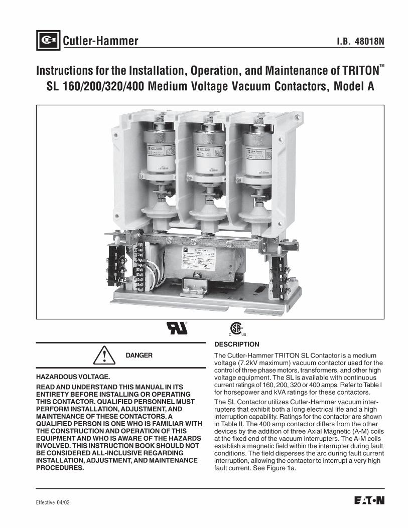
The Cutler-Hammer TRITON SL Contactor is a mediumvoltage (7.2kV maximum) vacuum contactor used for thecontrol of three phase motors, transformers, and other highvoltage equipment. The SL is available with continuouscurrent ratings of 160, 200, 320 or 400 amps. Refer to Table Ifor horsepower and kVA ratings for these contactors.The SL Contactor utilizes Cutler-Hammer vacuum inter-rupters that exhibit both a long electrical life and a highinterruption capability. Ratings for the contactor are shownin Table II. The 400 amp contactor differs from the otherdevices by the addition of three Axial Magnetic (A-M) coilsat the fixed end of the vacuum interrupters. The A-M coilsestablish a magnetic field within the interrupter during faultconditions. The field disperses the arc during fault currentinterruption, allowing the contactor to interrupt a very highfault current. See Figure 1a.
I.B. 48018NPage 2
Effective 04/03
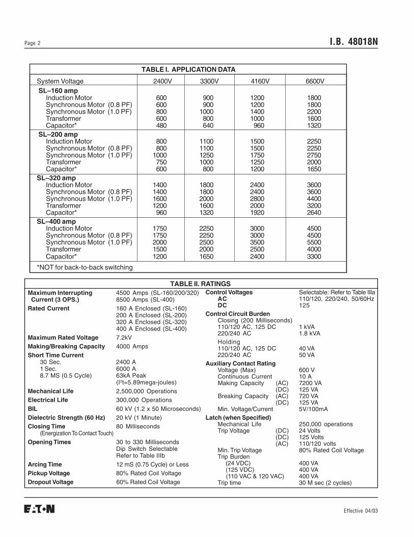
System Voltage 2400V 3300V 4160V 6600V SL–160 amp
Induction Motor 600 900 1200 1800Synchronous Motor (0.8 PF) 600 900 1200 1800Synchronous Motor (1.0 PF) 800 1000 1400 2200Transformer 600 800 1000 1600Capacitor* 480 640 960 1320
SL–200 ampInduction Motor 800 1100 1500 2250Synchronous Motor (0.8 PF) 800 1100 1500 2250Synchronous Motor (1.0 PF) 1000 1250 1750 2750Transformer 750 1000 1250 2000Capacitor* 600 800 1200 1650
SL–320 ampInduction Motor 1400 1800 2400 3600Synchronous Motor (0.8 PF) 1400 1800 2400 3600Synchronous Motor (1.0 PF) 1600 2000 2800 4400Transformer 1200 1600 2000 3200Capacitor* 960 1320 1920 2640
SL–400 ampInduction Motor 1750 2250 3000 4500Synchronous Motor (0.8 PF) 1750 2250 3000 4500Synchronous Motor (1.0 PF) 2000 2500 3500 5500Transformer 1500 2000 2500 4000Capacitor* 1200 1650 2400 3300
*NOT for back-to-back switching
TABLE I. APPLICATION DATA
TABLE II. RATINGSMaximum Interrupting 4500 Amps (SL-160/200/320) Current (3 OPS.) 8500 Amps (SL-400)Rated Current 160 A Enclosed (SL-160)
200 A Enclosed (SL-200)320 A Enclosed (SL-320)400 A Enclosed (SL-400)
Maximum Rated Voltage 7.2kVMaking/Breaking Capacity 4000 AmpsShort Time Current
30 Sec. 2400 A1 Sec. 6000 A8.7 MS (0.5 Cycle) 63kA Peak
(I2t=5.89mega-joules)Mechanical Life 2,500,000 OperationsElectrical Life 300,000 OperationsBIL 60 kV (1.2 x 50 Microseconds)Dielectric Strength (60 Hz) 20 kV (1 Minute)Closing Time 80 Milliseconds
(Energization To Contact Touch)Opening Times 30 to 330 Milliseconds
Dip Switch SelectableRefer to Table IIIb
Arcing Time 12 mS (0.75 Cycle) or LessPickup Voltage 80% Rated Coil VoltageDropout Voltage 60% Rated Coil Voltage
Control Voltages Selectable: Refer to Table IIIaAC 110/120, 220/240, 50/60HzDC 125
Control Circuit BurdenClosing (200 Milliseconds)110/120 AC, 125 DC 1 kVA220/240 AC 1.8 kVAHolding110/120 AC, 125 DC 40 VA220/240 AC 50 VA
Auxiliary Contact RatingVoltage (Max) 600 VContinuous Current 10 AMaking Capacity (AC) 7200 VA
(DC) 125 VABreaking Capacity (AC) 720 VA
(DC) 125 VAMin. Voltage/Current 5V/100mA
Latch (when Specified)Mechanical Life 250,000 operationsTrip Voltage (DC) 24 Volts
(DC) 125 Volts(AC) 110/120 volts
Min. Trip Voltage 80% Rated Coil VoltageTrip Burden (24 VDC) 400 VA (125 VDC) 400 VA (110 VAC & 120 VAC) 400 VATrip time 30 M sec (2 cycles)
I.B. 48018N Page 3
Effective 04/03
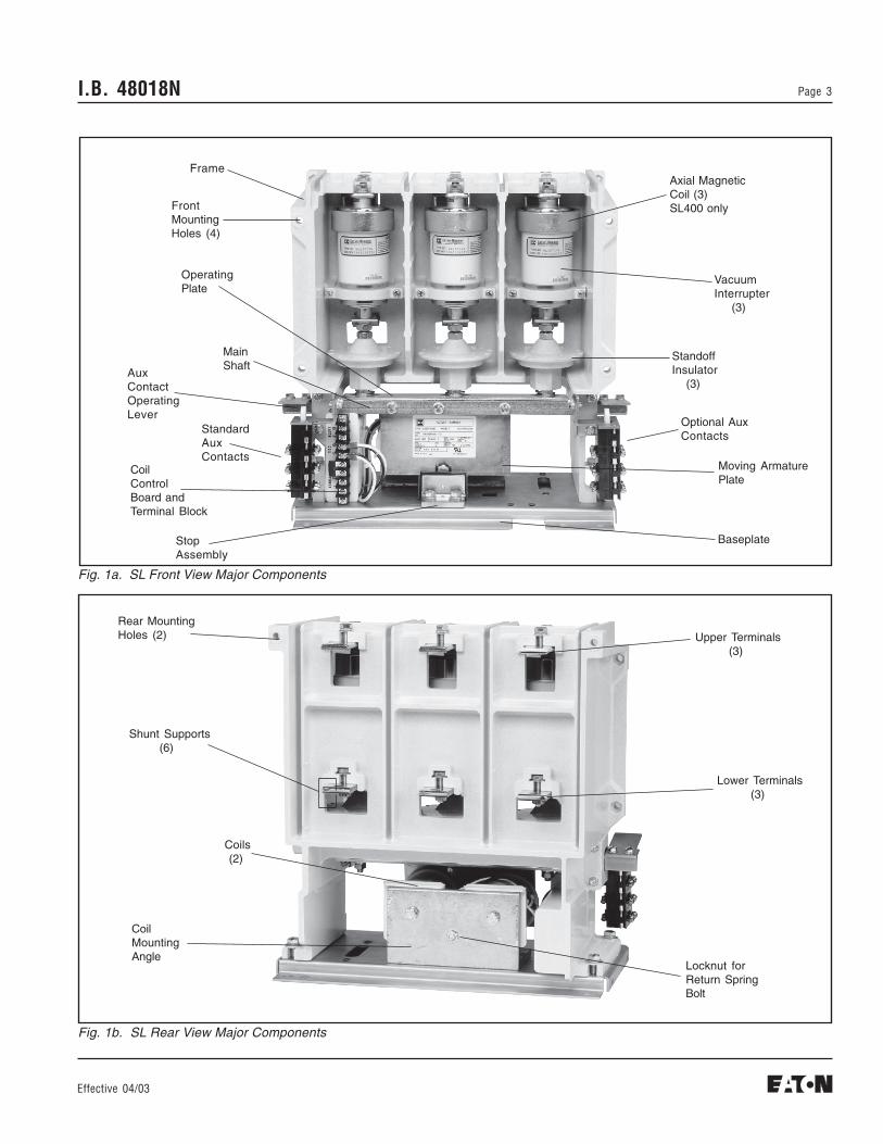
Fig. 1a. SL Front View Major Components
Fig. 1b. SL Rear View Major Components
Frame
FrontMountingHoles (4)
OperatingPlate
MainShaft
AuxContactOperatingLever
StandardAuxContacts
CoilControlBoard andTerminal Block
StopAssembly
Axial MagneticCoil (3)SL400 only
VacuumInterrupter (3)
StandoffInsulator (3)
Optional AuxContacts
Moving ArmaturePlate
Baseplate
Rear MountingHoles (2)
Shunt Supports (6)
CoilMountingAngle
Upper Terminals (3)
Lower Terminals (3)
Locknut forReturn SpringBolt
Coils (2)
I.B. 48018NPage 4
Effective 04/03
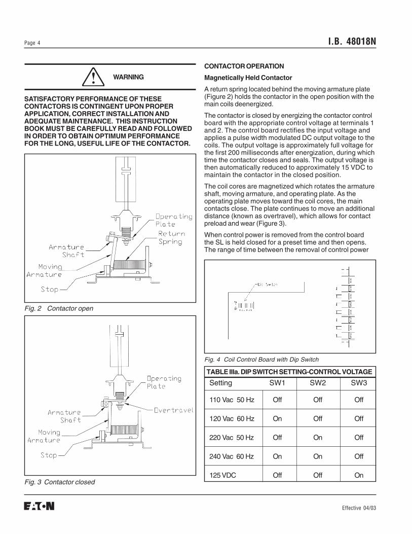
Fig. 4 Coil Control Board with Dip Switch
TABLE IIIa. DIP SWITCH SETTING-CONTROL VOLTAGE
Fig. 2 Contactor open
Fig. 3 Contactor closed
CONTACTOR OPERATION
Magnetically Held Contactor
A return spring located behind the moving armature plate(Figure 2) holds the contactor in the open position with themain coils deenergized.
The contactor is closed by energizing the contactor controlboard with the appropriate control voltage at terminals 1and 2. The control board rectifies the input voltage andapplies a pulse width modulated DC output voltage to thecoils. The output voltage is approximately full voltage forthe first 200 milliseconds after energization, during whichtime the contactor closes and seals. The output voltage isthen automatically reduced to approximately 15 VDC tomaintain the contactor in the closed position.
The coil cores are magnetized which rotates the armatureshaft, moving armature, and operating plate. As theoperating plate moves toward the coil cores, the maincontacts close. The plate continues to move an additionaldistance (known as overtravel), which allows for contactpreload and wear (Figure 3).
When control power is removed from the control boardthe SL is held closed for a preset time and then opens.The range of time between the removal of control power
SATISFACTORY PERFORMANCE OF THESECONTACTORS IS CONTINGENT UPON PROPERAPPLICATION, CORRECT INSTALLATION ANDADEQUATE MAINTENANCE. THIS INSTRUCTIONBOOK MUST BE CAREFULLY READ AND FOLLOWEDIN ORDER TO OBTAIN OPTIMUM PERFORMANCEFOR THE LONG, USEFUL LIFE OF THE CONTACTOR.
WARNING
Setting SW1 SW2 SW3
110 Vac 50 Hz Off Off Off
120 Vac 60 Hz On Off Off
220 Vac 50 Hz Off On Off
240 Vac 60 Hz On On Off
125 VDC Off Off On
I.B. 48018N Page 5
Effective 04/03
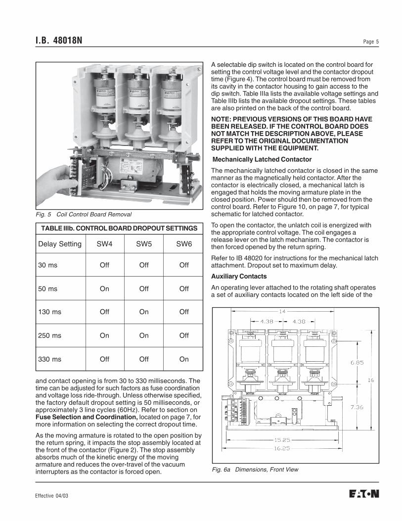
A selectable dip switch is located on the control board forsetting the control voltage level and the contactor dropouttime (Figure 4). The control board must be removed fromits cavity in the contactor housing to gain access to thedip switch. Table IIIa lists the available voltage settings andTable IIIb lists the available dropout settings. These tablesare also printed on the back of the control board.
NOTE: PREVIOUS VERSIONS OF THIS BOARD HAVEBEEN RELEASED. IF THE CONTROL BOARD DOESNOT MATCH THE DESCRIPTION ABOVE, PLEASEREFER TO THE ORIGINAL DOCUMENTATIONSUPPLIED WITH THE EQUIPMENT.
Mechanically Latched Contactor
The mechanically latched contactor is closed in the samemanner as the magnetically held contactor. After thecontactor is electrically closed, a mechanical latch isengaged that holds the moving armature plate in theclosed position. Power should then be removed from thecontrol board. Refer to Figure 10, on page 7, for typicalschematic for latched contactor.
To open the contactor, the unlatch coil is energized withthe appropriate control voltage. The coil engages arelease lever on the latch mechanism. The contactor isthen forced opened by the return spring.
Refer to IB 48020 for instructions for the mechanical latchattachment. Dropout set to maximum delay.
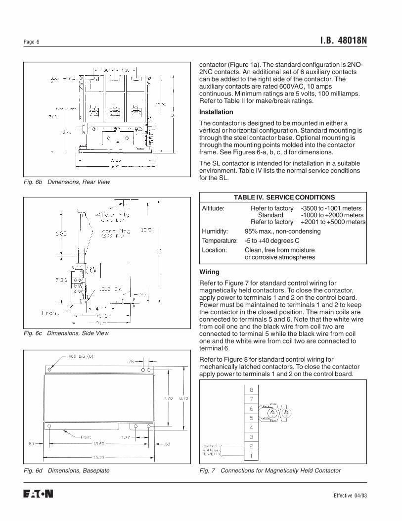
Fig. 6a Dimensions, Front View
Fig. 5 Coil Control Board Removal
TABLE IIIb. CONTROL BOARD DROPOUT SETTINGS
and contact opening is from 30 to 330 milliseconds. Thetime can be adjusted for such factors as fuse coordinationand voltage loss ride-through. Unless otherwise specified,the factory default dropout setting is 50 milliseconds, orapproximately 3 line cycles (60Hz). Refer to section onFuse Selection and Coordination, located on page 7, formore information on selecting the correct dropout time.
As the moving armature is rotated to the open position bythe return spring, it impacts the stop assembly located atthe front of the contactor (Figure 2). The stop assemblyabsorbs much of the kinetic energy of the movingarmature and reduces the over-travel of the vacuuminterrupters as the contactor is forced open.
Auxiliary Contacts
An operating lever attached to the rotating shaft operatesa set of auxiliary contacts located on the left side of the
Delay Setting SW4 SW5 SW6
30 ms Off Off Off
50 ms On Off Off
130 ms Off On Off
250 ms On On Off
330 ms Off Off On
I.B. 48018NPage 6
Effective 04/03
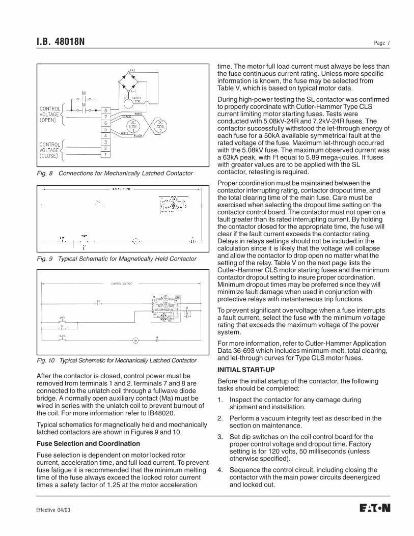
Fig. 7 Connections for Magnetically Held Contactor
Fig. 6b Dimensions, Rear View
Fig. 6c Dimensions, Side View
Fig. 6d Dimensions, Baseplate
contactor (Figure 1a). The standard configuration is 2NO-2NC contacts. An additional set of 6 auxiliary contactscan be added to the right side of the contactor. Theauxiliary contacts are rated 600VAC, 10 ampscontinuous. Minimum ratings are 5 volts, 100 milliamps.Refer to Table II for make/break ratings.
Installation
The contactor is designed to be mounted in either avertical or horizontal configuration. Standard mounting isthrough the steel contactor base. Optional mounting isthrough the mounting points molded into the contactorframe. See Figures 6-a, b, c, d for dimensions.
The SL contactor is intended for installation in a suitableenvironment. Table IV lists the normal service conditionsfor the SL.
Wiring
Refer to Figure 7 for standard control wiring formagnetically held contactors. To close the contactor,apply power to terminals 1 and 2 on the control board.Power must be maintained to terminals 1 and 2 to keepthe contactor in the closed position. The main coils areconnected to terminals 5 and 6. Note that the white wirefrom coil one and the black wire from coil two areconnected to terminal 5 while the black wire from coilone and the white wire from coil two are connected toterminal 6.
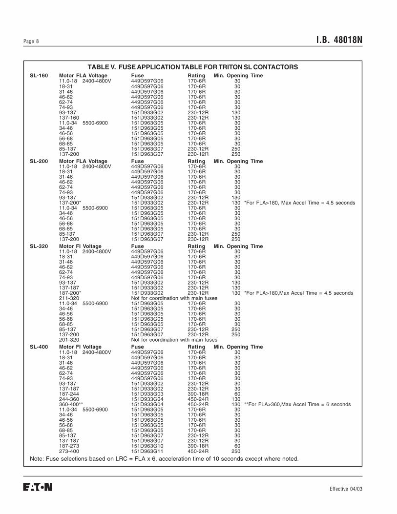
Refer to Figure 8 for standard control wiring formechanically latched contactors. To close the contactorapply power to terminals 1 and 2 on the control board.
TABLE IV. SERVICE CONDITIONS
Altitude: Refer to factory -3500 to -1001 metersStandard -1000 to +2000 meters
Refer to factory +2001 to +5000 metersHumidity: 95% max., non-condensingTemperature: -5 to +40 degrees CLocation: Clean, free from moisture
or corrosive atmospheres
I.B. 48018N Page 7
Effective 04/03
After the contactor is closed, control power must beremoved from terminals 1 and 2.Terminals 7 and 8 areconnected to the unlatch coil through a fullwave diodebridge. A normally open auxiliary contact (Ma) must bewired in series with the unlatch coil to prevent burnout ofthe coil. For more information refer to IB48020.
Typical schematics for magnetically held and mechanicallylatched contactors are shown in Figures 9 and 10.
Fuse Selection and Coordination
Fuse selection is dependent on motor locked rotorcurrent, acceleration time, and full load current. To preventfuse fatigue it is recommended that the minimum meltingtime of the fuse always exceed the locked rotor currenttimes a safety factor of 1.25 at the motor acceleration
Fig. 9 Typical Schematic for Magnetically Held Contactor
time. The motor full load current must always be less thanthe fuse continuous current rating. Unless more specificinformation is known, the fuse may be selected fromTable V, which is based on typical motor data.
During high-power testing the SL contactor was confirmedto properly coordinate with Cutler-Hammer Type CLScurrent limiting motor starting fuses. Tests wereconducted with 5.08kV-24R and 7.2kV-24R fuses. Thecontactor successfully withstood the let-through energy ofeach fuse for a 50kA available symmetrical fault at therated voltage of the fuse. Maximum let-through occurredwith the 5.08kV fuse. The maximum observed current wasa 63kA peak, with I2t equal to 5.89 mega-joules. If fuseswith greater values are to be applied with the SLcontactor, retesting is required.
Proper coordination must be maintained between thecontactor interrupting rating, contactor dropout time, andthe total clearing time of the main fuse. Care must beexercised when selecting the dropout time setting on thecontactor control board. The contactor must not open on afault greater than its rated interrupting current. By holdingthe contactor closed for the appropriate time, the fuse willclear if the fault current exceeds the contactor rating.Delays in relays settings should not be included in thecalculation since it is likely that the voltage will collapseand allow the contactor to drop open no matter what thesetting of the relay. Table V on the next page lists theCutler-Hammer CLS motor starting fuses and the minimumcontactor dropout setting to insure proper coordination.Minimum dropout times may be preferred since they willminimize fault damage when used in conjunction withprotective relays with instantaneous trip functions.
To prevent significant overvoltage when a fuse interruptsa fault current, select the fuse with the minimum voltagerating that exceeds the maximum voltage of the powersystem.
For more information, refer to Cutler-Hammer ApplicationData 36-693 which includes minimum-melt, total clearing,and let-through curves for Type CLS motor fuses.
INITIAL START-UP
Before the initial startup of the contactor, the followingtasks should be completed:
1. Inspect the contactor for any damage duringshipment and installation.
2. Perform a vacuum integrity test as described in thesection on maintenance.
3. Set dip switches on the coil control board for theproper control voltage and dropout time. Factorysetting is for 120 volts, 50 milliseconds (unlessotherwise specified).
4. Sequence the control circuit, including closing thecontactor with the main power circuits deenergizedand locked out.
Fig. 8 Connections for Mechanically Latched Contactor
Fig. 10 Typical Schematic for Mechanically Latched Contactor
I.B. 48018NPage 8
Effective 04/03
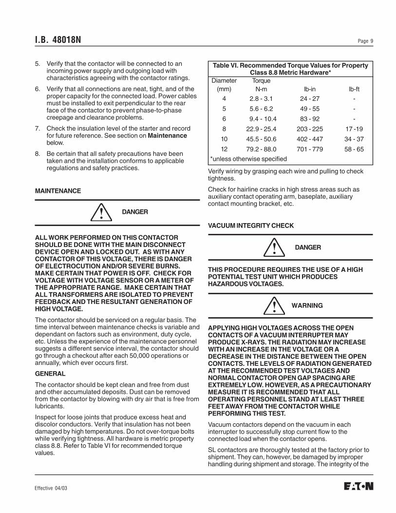
TABLE V. FUSE APPLICATION TABLE FOR TRITON SL CONTACTORSSL-160 Motor FLA Voltage Fuse Rating Min. Opening Time
11.0-18 2400-4800V 449D597G06 170-6R 3018-31 449D597G06 170-6R 3031-46 449D597G06 170-6R 3046-62 449D597G06 170-6R 3062-74 449D597G06 170-6R 3074-93 449D597G06 170-6R 3093-137 151D933G02 230-12R 130137-160 151D933G02 230-12R 13011.0-34 5500-6900 151D963G05 170-6R 3034-46 151D963G05 170-6R 3046-56 151D963G05 170-6R 3056-68 151D963G05 170-6R 3068-85 151D963G05 170-6R 3085-137 151D963G07 230-12R 250137-200 151D963G07 230-12R 250
SL-200 Motor FLA Voltage Fuse Rating Min. Opening Time11.0-18 2400-4800V 449D597G06 170-6R 3018-31 449D597G06 170-6R 3031-46 449D597G06 170-6R 3046-62 449D597G06 170-6R 3062-74 449D597G06 170-6R 3074-93 449D597G06 170-6R 3093-137 151D933G02 230-12R 130137-200* 151D933G02 230-12R 130 *For FLA>180, Max Accel Time = 4.5 seconds11.0-34 5500-6900 151D963G05 170-6R 3034-46 151D963G05 170-6R 3046-56 151D963G05 170-6R 3056-68 151D963G05 170-6R 3068-85 151D963G05 170-6R 3085-137 151D963G07 230-12R 250137-200 151D963G07 230-12R 250
SL-320 Motor FI Voltage Fuse Rating Min. Opening Time11.0-18 2400-4800V 449D597G06 170-6R 3018-31 449D597G06 170-6R 3031-46 449D597G06 170-6R 3046-62 449D597G06 170-6R 3062-74 449D597G06 170-6R 3074-93 449D597G06 170-6R 3093-137 151D933G02 230-12R 130137-187 151D933G02 230-12R 130187-200* 151D933G02 230-12R 130 *For FLA>180,Max Accel Time = 4.5 seconds211-320 Not for coordination with main fuses11.0-34 5500-6900 151D963G05 170-6R 3034-46 151D963G05 170-6R 3046-56 151D963G05 170-6R 3056-68 151D963G05 170-6R 3068-85 151D963G05 170-6R 3085-137 151D963G07 230-12R 250137-200 151D963G07 230-12R 250201-320 Not for coordination with main fuses
SL-400 Motor FI Voltage Fuse Rating Min. Opening Time11.0-18 2400-4800V 449D597G06 170-6R 3018-31 449D597G06 170-6R 3031-46 449D597G06 170-6R 3046-62 449D597G06 170-6R 3062-74 449D597G06 170-6R 3074-93 449D597G06 170-6R 3093-137 151D933G02 230-12R 30137-187 151D933G02 230-12R 30187-244 151D933G03 390-18R 60244-360 151D933G04 450-24R 130360-400** 151D933G04 450-24R 130 **For FLA>360,Max Accel Time = 6 seconds11.0-34 5500-6900 151D963G05 170-6R 3034-46 151D963G05 170-6R 3046-56 151D963G05 170-6R 3056-68 151D963G05 170-6R 3068-85 151D963G05 170-6R 3085-137 151D963G07 230-12R 30137-187 151D963G07 230-12R 30187-273 151D963G10 390-18R 60273-400 151D963G11 450-24R 250
Note: Fuse selections based on LRC = FLA x 6, acceleration time of 10 seconds except where noted.
I.B. 48018N Page 9
Effective 04/03
Verify wiring by grasping each wire and pulling to checktightness.
Check for hairline cracks in high stress areas such asauxiliary contact operating arm, baseplate, auxiliarycontact mounting bracket, etc.
VACUUM INTEGRITY CHECK
THIS PROCEDURE REQUIRES THE USE OF A HIGHPOTENTIAL TEST UNIT WHICH PRODUCESHAZARDOUS VOLTAGES.
APPLYING HIGH VOLTAGES ACROSS THE OPENCONTACTS OF A VACUUM INTERRUPTER MAYPRODUCE X-RAYS. THE RADIATION MAY INCREASEWITH AN INCREASE IN THE VOLTAGE OR ADECREASE IN THE DISTANCE BETWEEN THE OPENCONTACTS. THE LEVELS OF RADIATION GENERATEDAT THE RECOMMENDED TEST VOLTAGES ANDNORMAL CONTACTOR OPEN GAP SPACING AREEXTREMELY LOW. HOWEVER, AS A PRECAUTIONARYMEASURE IT IS RECOMMENDED THAT ALLOPERATING PERSONNEL STAND AT LEAST THREEFEET AWAY FROM THE CONTACTOR WHILEPERFORMING THIS TEST.
Vacuum contactors depend on the vacuum in eachinterrupter to successfully stop current flow to theconnected load when the contactor opens.
SL contactors are thoroughly tested at the factory prior toshipment. They can, however, be damaged by improperhandling during shipment and storage. The integrity of the
DANGER
Table VI. Recommended Torque Values for PropertyClass 8.8 Metric Hardware*
WARNING
Diameter(mm)
4
5
6
8
10
12
TorqueN-m
2.8 - 3.1
5.6 - 6.2
9.4 - 10.4
22.9 - 25.4
45.5 - 50.6
79.2 - 88.0
lb-in
24 - 27
49 - 55
83 - 92
203 - 225
402 - 447
701 - 779
lb-ft
-
-
-
17 -19
34 - 37
58 - 65
*unless otherwise specified
DANGER
5. Verify that the contactor will be connected to anincoming power supply and outgoing load withcharacteristics agreeing with the contactor ratings.
6. Verify that all connections are neat, tight, and of theproper capacity for the connected load. Power cablesmust be installed to exit perpendicular to the rearface of the contactor to prevent phase-to-phasecreepage and clearance problems.
7. Check the insulation level of the starter and recordfor future reference. See section on Maintenancebelow.
8. Be certain that all safety precautions have beentaken and the installation conforms to applicableregulations and safety practices.
MAINTENANCE
ALL WORK PERFORMED ON THIS CONTACTORSHOULD BE DONE WITH THE MAIN DISCONNECTDEVICE OPEN AND LOCKED OUT. AS WITH ANYCONTACTOR OF THIS VOLTAGE, THERE IS DANGEROF ELECTROCUTION AND/OR SEVERE BURNS.MAKE CERTAIN THAT POWER IS OFF. CHECK FORVOLTAGE WITH VOLTAGE SENSOR OR A METER OFTHE APPROPRIATE RANGE. MAKE CERTAIN THATALL TRANSFORMERS ARE ISOLATED TO PREVENTFEEDBACK AND THE RESULTANT GENERATION OFHIGH VOLTAGE.
The contactor should be serviced on a regular basis. Thetime interval between maintenance checks is variable anddependant on factors such as environment, duty cycle,etc. Unless the experience of the maintenance personnelsuggests a different service interval, the contactor shouldgo through a checkout after each 50,000 operations orannually, which ever occurs first.
GENERAL
The contactor should be kept clean and free from dustand other accumulated deposits. Dust can be removedfrom the contactor by blowing with dry air that is free fromlubricants.
Inspect for loose joints that produce excess heat anddiscolor conductors. Verify that insulation has not beendamaged by high temperatures. Do not over-torque boltswhile verifying tightness. All hardware is metric propertyclass 8.8. Refer to Table VI for recommended torquevalues.
I.B. 48018NPage 10
Effective 04/03
VI REPLACEMENT
If the vacuum interrupters fail the vacuum integrity orwear check, or if they have more than 300,000operations, they must be replaced. The three interruptersmust be replaced as a set.
THERE ARE BELLOWS IN EACH INTERRUPTER THATSEAL THE MOVING CONTACT FROM THEATMOSPHERE. THESE BELLOWS ARE FRAGILE ANDMUST BE PROTECTED FROM ANY TORSIONALLOADING. AN APPROPRIATE TOOL MUST SUPPORTTHE MACHINED FLATS ON EACH END OF THEINTERRUPTER WHEN TIGHTENING ANY HARDWAREON THE INTERRUPTER. BOTTLE WRENCH, CUTLER-HAMMER PART NUMBER 4A36081H01, IS PROVIDEDWITH EACH SET OF REPLACEMENT VI’S ANDSHOULD BE USED IN THIS APPLICATION.
Remove each VI using the steps listed below:
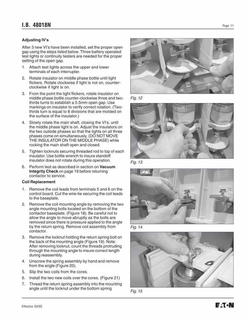
1. Loosen locknut securing threaded rod to top ofstandoff insulator (Figure 12). Note the number ofthreads between the two 10mm nuts.
2. Rotate insulator clockwise to screw insulator offthreaded rod.
3. Remove clamp securing lower end of VI to housing(Figure 13).
4. Remove bolt and shunt supports securing end oflower terminal to housing (Figure 14).
5. Remove the bolt securing VI to upper terminal(Figure 15).
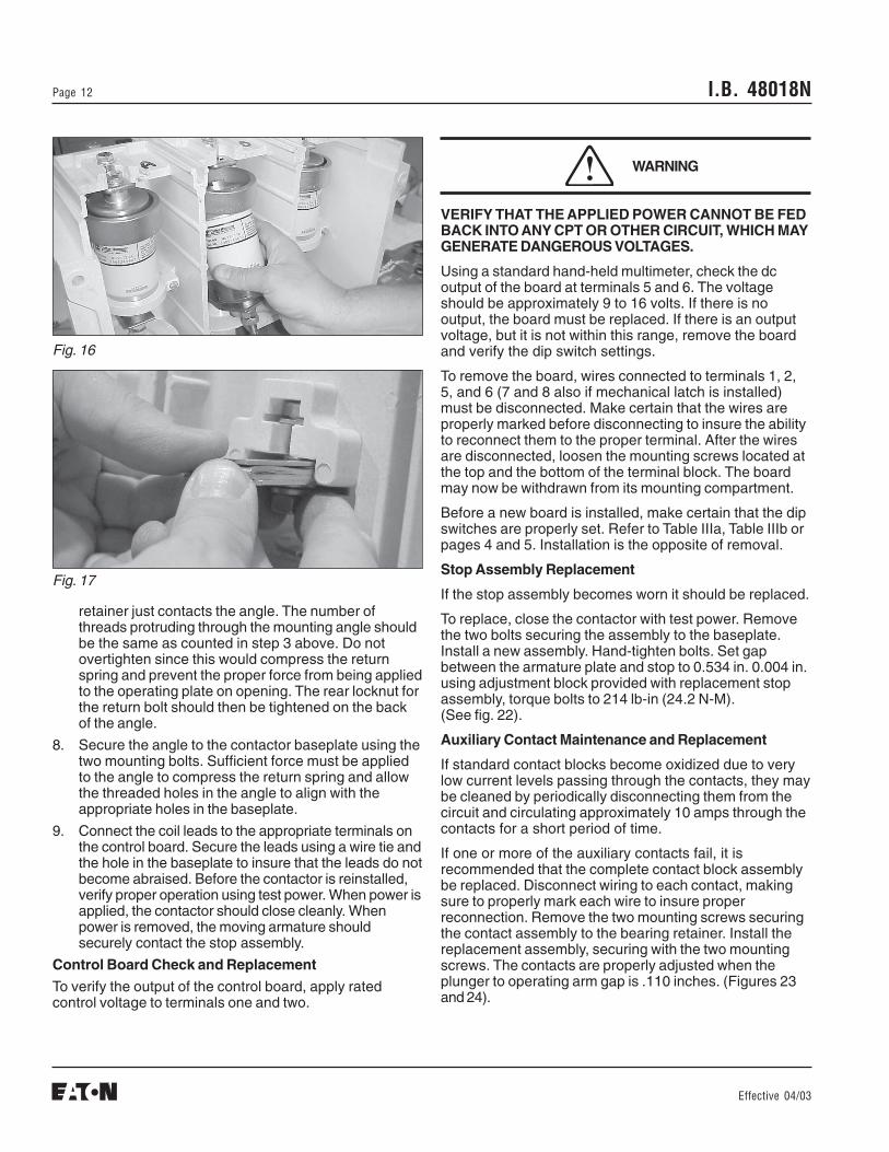
6. Hold insulator down and rotate lower portion of VIassembly forward to remove (Figure 16).
7. Insert new VI assembly (reverse of step 6).
8. Install the bolt securing VI to upper terminal, do nottighten.
9. Install bolt and shunt supports securing lowerterminal to housing (Figure 17). When tighteninginsure laminated shunt is straight and shunt supportsare in correct position.
10. Tighten bolt securing VI to upper terminal whileholding bottle wrench on upper VI stem. Torque to 200lb-in (22.6 Nm). Insure the laminated shunt is nottwisted.
11. Install clamp securing lower end of VI to housing.
12. Rotate insulator counter-clockwise until the number ofthreads noted in step 1 is obtained.
CAUTION
vacuum interrupters should therefore be verified before thecontactor is energized for the first time. The check shouldalso be made each time the contactor is serviced orrepaired, otherwise the test should be performed each50,000 operations or annually, whichever occurs first.
To verify the integrity of the vacuum interrupters a voltageof 16kV-ac should be applied across the open contacts ofthe interrupters. The voltage should be applied for 60seconds without breakdown. Breakdown is defined as acurrent of 5mA or more flowing across the open contacts.Note that approximately 1mA of current will flow througheach interrupter during the AC test due to the capacitanceof the vacuum interrupter.
If a DC high potential test unit is used, make certain thatthe peak voltage does not exceed 23kV, the peak of thecorresponding AC RMS test voltage. A megger cannot beused to verify vacuum integrity due to its limited outputvoltage.
INTERRUPTER WEAR CHECK
The interrupters used in the SL contactor are designed forlong electrical life. Replacement should be at 300,000operations except in cases of plugging or jogging whichmay require more frequent replacement. Verification ofcontact wear can be made by following the procedurebelow.
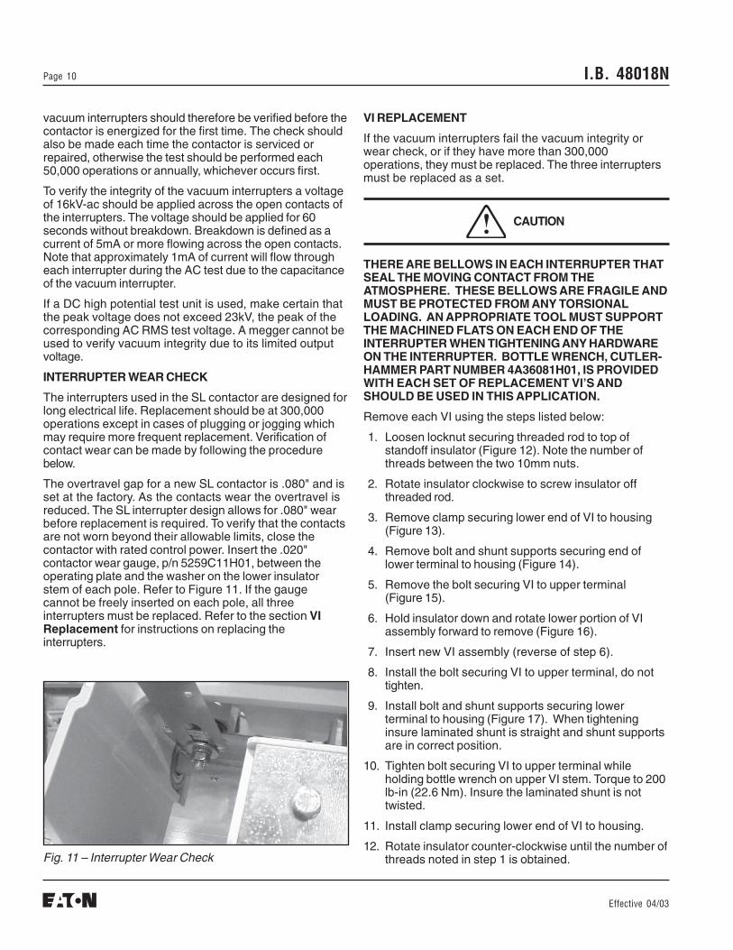
The overtravel gap for a new SL contactor is .080" and isset at the factory. As the contacts wear the overtravel isreduced. The SL interrupter design allows for .080" wearbefore replacement is required. To verify that the contactsare not worn beyond their allowable limits, close thecontactor with rated control power. Insert the .020"contactor wear gauge, p/n 5259C11H01, between theoperating plate and the washer on the lower insulatorstem of each pole. Refer to Figure 11. If the gaugecannot be freely inserted on each pole, all threeinterrupters must be replaced. Refer to the section VIReplacement for instructions on replacing theinterrupters.
Fig. 11 – Interrupter Wear Check
I.B. 48018N Page 11
Effective 04/03
Fig. 12
Fig. 13
Fig. 14
Fig. 15
Adjusting IV's
After 3 new VI’s have been installed, set the proper opengap using the steps listed below. Three battery operatedtest lights or continuity testers are needed for the propersetting of the open gap.
1. Attach test lights across the upper and lowerterminals of each interrupter.
2. Rotate insulator on middle phase bottle until lightflickers. Rotate clockwise if light is not on, counter-clockwise if light is on.
3. From the point the light flickers, rotate insulator onmiddle phase bottle counter-clockwise three and two-thirds turns to establish a 5.5mm open gap. Usemarkings on insulator to verify correct rotation. (Two-thirds turn is equal to 8 divisions that are molded onthe surface of the insulator.)
4. Slowly rotate the main shaft, closing the VI's, untilthe middle phase light is on. Adjust the insulators onthe two outside phases so that the lights on all threephases come on simultaneously, (DO NOT MOVETHE INSULATOR ON THE MIDDLE PHASE) whilerocking the main shaft open and closed.
5. Tighten locknuts securing threaded rod to top of eachinsulator. Use bottle wrench to insure standoffinsulator does not rotate during this operation.
6. Perform test as described in section on VacuumIntegrity Check on page 19 before returningcontactor to service.
Coil Replacement
1. Remove the coil leads from terminals 5 and 6 on thecontrol board. Cut the wire-tie securing the coil leadsto the baseplate.
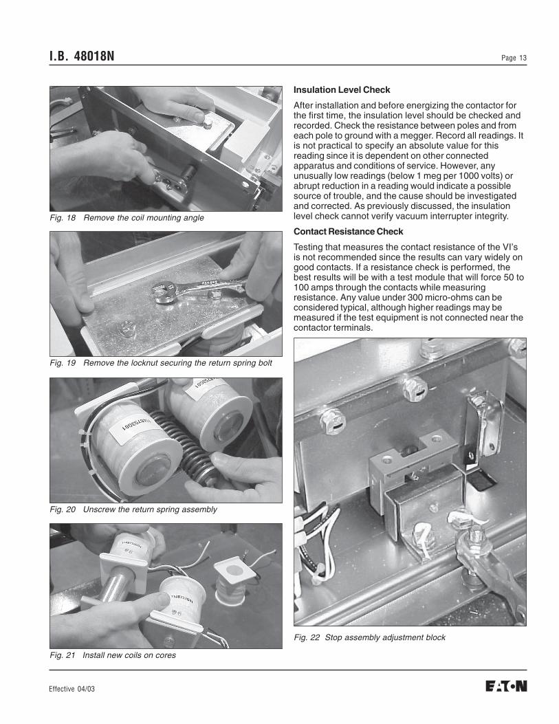
2. Remove the coil mounting angle by removing the twoangle mounting bolts located on the bottom of thecontactor baseplate. (Figure 18). Be careful not toallow the angle to move abruptly as the bolts areremoved since there is pressure applied to the angleby the return spring. Remove coil assembly fromcontactor.
3. Remove the locknut holding the return spring bolt onthe back of the mounting angle (Figure 19). Note:After removing locknut, count the threads protrudingthrough the mounting angle to insure correct lengthduring reassembly.
4. Unscrew the spring assembly by hand and removefrom the angle (Figure 20).
5. Slip the two coils from the cores.
6. Install the two new coils over the cores. (Figure 21)
7. Thread the return spring assembly into the mountingangle until the locknut under the bottom spring
I.B. 48018NPage 12
Effective 04/03
VERIFY THAT THE APPLIED POWER CANNOT BE FEDBACK INTO ANY CPT OR OTHER CIRCUIT, WHICH MAYGENERATE DANGEROUS VOLTAGES.
Using a standard hand-held multimeter, check the dcoutput of the board at terminals 5 and 6. The voltageshould be approximately 9 to 16 volts. If there is nooutput, the board must be replaced. If there is an outputvoltage, but it is not within this range, remove the boardand verify the dip switch settings.
To remove the board, wires connected to terminals 1, 2,5, and 6 (7 and 8 also if mechanical latch is installed)must be disconnected. Make certain that the wires areproperly marked before disconnecting to insure the abilityto reconnect them to the proper terminal. After the wiresare disconnected, loosen the mounting screws located atthe top and the bottom of the terminal block. The boardmay now be withdrawn from its mounting compartment.
Before a new board is installed, make certain that the dipswitches are properly set. Refer to Table IIIa, Table IIIb orpages 4 and 5. Installation is the opposite of removal.
Stop Assembly Replacement
If the stop assembly becomes worn it should be replaced.
To replace, close the contactor with test power. Removethe two bolts securing the assembly to the baseplate.Install a new assembly. Hand-tighten bolts. Set gapbetween the armature plate and stop to 0.534 in. 0.004 in.using adjustment block provided with replacement stopassembly, torque bolts to 214 lb-in (24.2 N-M).(See fig. 22).
Auxiliary Contact Maintenance and Replacement
If standard contact blocks become oxidized due to verylow current levels passing through the contacts, they maybe cleaned by periodically disconnecting them from thecircuit and circulating approximately 10 amps through thecontacts for a short period of time.
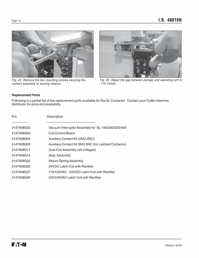
If one or more of the auxiliary contacts fail, it isrecommended that the complete contact block assemblybe replaced. Disconnect wiring to each contact, makingsure to properly mark each wire to insure properreconnection. Remove the two mounting screws securingthe contact assembly to the bearing retainer. Install thereplacement assembly, securing with the two mountingscrews. The contacts are properly adjusted when theplunger to operating arm gap is .110 inches. (Figures 23and 24).
WARNING
Fig. 16
Fig. 17
retainer just contacts the angle. The number ofthreads protruding through the mounting angle shouldbe the same as counted in step 3 above. Do notovertighten since this would compress the returnspring and prevent the proper force from being appliedto the operating plate on opening. The rear locknut forthe return bolt should then be tightened on the backof the angle.
8. Secure the angle to the contactor baseplate using thetwo mounting bolts. Sufficient force must be appliedto the angle to compress the return spring and allowthe threaded holes in the angle to align with theappropriate holes in the baseplate.
9. Connect the coil leads to the appropriate terminals onthe control board. Secure the leads using a wire tie andthe hole in the baseplate to insure that the leads do notbecome abraised. Before the contactor is reinstalled,verify proper operation using test power. When power isapplied, the contactor should close cleanly. Whenpower is removed, the moving armature shouldsecurely contact the stop assembly.
Control Board Check and Replacement
To verify the output of the control board, apply ratedcontrol voltage to terminals one and two.
I.B. 48018N Page 13
Effective 04/03
Fig. 19 Remove the locknut securing the return spring bolt
Fig. 20 Unscrew the return spring assembly
Fig. 21 Install new coils on cores
Insulation Level Check
After installation and before energizing the contactor forthe first time, the insulation level should be checked andrecorded. Check the resistance between poles and fromeach pole to ground with a megger. Record all readings. Itis not practical to specify an absolute value for thisreading since it is dependent on other connectedapparatus and conditions of service. However, anyunusually low readings (below 1 meg per 1000 volts) orabrupt reduction in a reading would indicate a possiblesource of trouble, and the cause should be investigatedand corrected. As previously discussed, the insulationlevel check cannot verify vacuum interrupter integrity.
Contact Resistance Check
Testing that measures the contact resistance of the VI’sis not recommended since the results can vary widely ongood contacts. If a resistance check is performed, thebest results will be with a test module that will force 50 to100 amps through the contacts while measuringresistance. Any value under 300 micro-ohms can beconsidered typical, although higher readings may bemeasured if the test equipment is not connected near thecontactor terminals.
Fig. 18 Remove the coil mounting angle
Fig. 22 Stop assembly adjustment block
I.B. 48018NPage 14
Effective 04/03
Replacement Parts
Following is a partial list of the replacement parts available for the SL Contactor. Contact your Cutler-Hammerdistributor for price and availability.
P/n Description
————— ———————————————
2147A58G02 Vacuum Interrupter Assembly for SL-160/200/320/400
2147A58G03 Coil Control Board
2147A58G04 Auxiliary Contact Kit (2NO-2NC)
2147A58G05 Auxiliary Contact Kit 3NO-3NC (for Latched Contactor)
2147A58G11 Dual Coil Assembly (all voltages)
2147A58G14 Stop Assembly
2147A58G22 Return Spring Assembly
2147A58G25 24VDC Latch Coil with Rectifier
2147A58G27 110/120VAC, 125VDC Latch Coil with Rectifier
2147A58G28 220/240VAC Latch Coil with Rectifier
Fig. 24 Adjust the gap between plunger and operating arm to.110 inches
Fig. 23 Remove the two mounting screws securing thecontact assembly to bearing retainer

I.B. 48018N Page 15
Effective 04/03

I.B. 48018NPage 16
Effective 04/03Printed in U.S.A./CCI
Cutler-Hammer221 Heywood RoadArden, NC 28704


![Cutler-Hammer NEMA Contactors & Starters Thermal ... January 2001 Vol. 2, Ref. No. 10053] NEMA Contactors & Starters Thermal Overload Relays Freedom Line 33-37 Table 33-74. Standard](https://img.pdfslide.us/doc/110x75/5ac0a7ec7f8b9a213f8c3cf8/cutler-hammer-nema-contactors-starters-thermal-january-2001-vol-2-ref-no.jpg)
![Cutler-Hammer - DLE ELECTRIC SUPPLY - Electrical ...dlelectricsupply.com/files/A200M1CBP.pdfCutler-Hammer January 2001 Vol. 2, Ref No. [0137] NEMA Contactors & Starters Starters —](https://img.pdfslide.us/doc/110x75/5ac0a7ec7f8b9a213f8c3ce8/cutler-hammer-dle-electric-supply-electrical-january-2001-vol-2-ref-no.jpg)