Embed Size (px)
Citation preview
SKYWAY80 GHz Gigabit Ethernet
PTP Microwave Radio System
SKYWAY-GB-X SERIES 80 GHz Gigabit Ethernet
PTP Microwave Radio System
Installation Guide
August, 2016 Rev 1.0
PTP Microwave Radio System
GB-X Installation Guide
ii
Table of Contents
1 Introduction .......................................... 1
1.1 Purpose .......................................... 1
1.2 Prior Knowledge ............................ 1
1.3 Contact Information ....................... 2
2 Site Planning ......................................... 3
2.1 General .......................................... 3
2.2 Equipment Checklist ...................... 3
2.3 Line of Sight ................................... 3
2.4 Link Distance ................................. 4
2.5 Antenna Location ........................... 5
2.6 GB-X Cover Removal ..................... 5
2.7 Radio Ports and Interface .............. 6
2.8 SFP Options ................................... 7
2.9 SFP Modules Installation .............. 8
2.10 Cabling Considerations ................. 9
2.11 Power Supply Connection ............ 15
2.12 Grounding & Lightning ............... 16
2.13 Environmental .............................. 17
2.14 Cabling Diagram ......................... 18
3 Installation .......................................... 21
3.1 General ........................................ 21
3.2 Equipment Unpacking .................. 21
3.3 Installation Tools ............................... 22
3.3 Antenna Mount Installation ......... 23
3.4 Antenna and Radio Installation ... 23
3.5 Cable Installation......................... 26
3.6 Antenna Alignment ....................... 30
4 Radio Link Status Indicators ............ 41
4.1 Normal Operation ........................ 41
4.2 LED Functionality during Radio
Operation ................................................. 42
4.3 GB-X Cover Installation .............. 44
4.4 Connecting Network Equipment .. 45
4.5 Network Port Link and Statistics . 45
5 1+1 Protection and 2+0 OMT-80
Installation .................................................. 46
5.1 1+1 Protection Overview ............. 46
5.2 2+0 OMT-80 Overview ................ 48
5.3 Protection Product Configuration 49
5.4 Cabling Considerations ............... 50
5.5 Changing Polarity on 1+1
Protection Couplers ................................. 55
5.6 Antenna Mount Installation ......... 56
5.7 RF Coupler Assembly and Radio
Installation ............................................... 56
5.8 Cable Installation......................... 60
5.9 Protection Active and Standby
Radio Cabling – Ethernet Fiber Pairs,
Splitters, and SFPs ................................... 60
5.10 2+0 OMT-80 Fiber, Power &
Ground Cabling ....................................... 62
5.11 2+0 OMT Antenna Polarization
Adjustment................................................ 63
Appendix A Troubleshooting ................ 64
Appendix B RSSI Voltage Chart .......... 66
Appendix C Reset Button ...................... 67
Performing Hard Reset ............................ 67
Reset Button Functionality ....................... 67
GB-X Installation Guide
1
1 Introduction
1.1 Purpose
The information in this guide is directed to persons who must perform or coordinate the tasks
associated with the process of installing wireless communication devices and planning
communication network applications.
Installation of a 1+0 non-protected GB-X system is described in sections 2 -5.
Installation of 1+1 Hot Standby Protection (Protection) and 2+0 Orthogonal Mode Transducer
(OMT-80) GB-X systems are described in section 5. The appendices provide additional information
for GB-X systems with any of these options.
1.2 Prior Knowledge
This guide assumes the operator has at least basic experience with, and an understanding of, wireless
technology; and some familiarity with configuring and operating networking equipment. Preferably,
the person installing this equipment fully understands the information covered in this guide, prior to
attempting these procedures.
DANGER, WARNING, and NOTE statements have been placed in various sections throughout
this document to alert personnel of possible traffic-affecting issues, and to provide additional tips
and helpful information. These statements should be closely observed.
Symbol Description
Indicates that personal injury can result if the user does not
comply with the given instruction.
A DANGER statement will describe the potential hazard, its
possible consequences, and the steps to perform to avoid
personal injury.
Indicates that equipment damage, process failure, and/or loss
of data can result if the user does not comply with the given
instructions.
A WARNING statement will describe the potential hazard, its
possible consequences, and the steps to perform to avoid
serious equipment damage.
GB-X Installation Guide
2
Provides supplementary information to emphasize a point or
procedure, or provides a tip for easier operation.
1.3 Contact Information
Return Material Authorization
Should Solectek equipment have to be returned for repair or replacement, a Return Material
Authorization (RMA) number must be obtained in advance from Solectek. When returning
equipment, be sure to clearly indicate the RMA number on the outside of the shipping carton.
GB-X Installation Guide
3
2 Site Planning
2.1 General
Before the start of any installation, a survey of the planned deployment site should be conducted.
The surveying personnel should be fully familiar with the details and requirements needed to
successfully install the GB-X radio system.
2.2 Equipment Checklist
The following lists suggested equipment the site survey team may require:
• Binoculars (not always required)
• WAAS-capable GPS location device
• Tape measure to determine distances for cable runs to ingress points
• Digital camera (not always required)
• Site survey report form to document and help assess site
• Signaling mirror (not always required)
2.3 Line of Sight
The GB-X 80GHz Wireless Gigabit Ethernet link requires Line of Sight (LOS) for proper operation.
Binoculars and spotting mirrors may be used to assist in the confirmation of LOS.
Path planning should include an investigation into future building plans that could block the LOS
path and other long-term incremental obstructions, such as tree growth. Intermittent obstructions,
such as aircraft at a nearby airport, should also be considered.
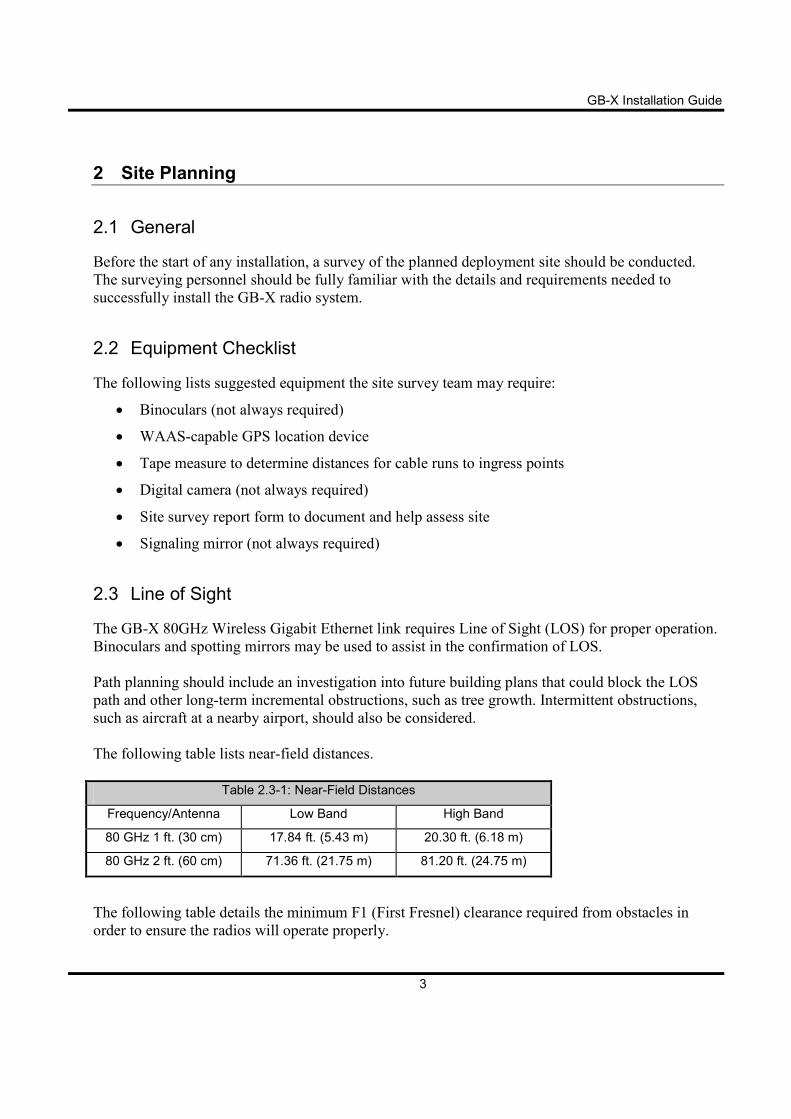
The following table lists near-field distances.
Table 2.3-1: Near-Field Distances
Frequency/Antenna Low Band High Band
80 GHz 1 ft. (30 cm) 17.84 ft. (5.43 m) 20.30 ft. (6.18 m)
80 GHz 2 ft. (60 cm) 71.36 ft. (21.75 m) 81.20 ft. (24.75 m)
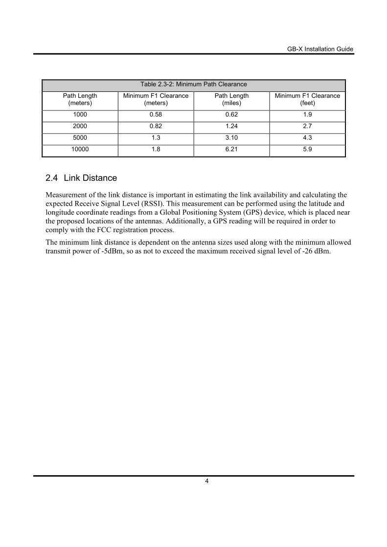
The following table details the minimum F1 (First Fresnel) clearance required from obstacles in
order to ensure the radios will operate properly.
GB-X Installation Guide
4
Table 2.3-2: Minimum Path Clearance
Path Length (meters)
Minimum F1 Clearance (meters)
Path Length (miles)
Minimum F1 Clearance (feet)
1000 0.58 0.62 1.9
2000 0.82 1.24 2.7
5000 1.3 3.10 4.3
10000 1.8 6.21 5.9
2.4 Link Distance
Measurement of the link distance is important in estimating the link availability and calculating the
expected Receive Signal Level (RSSI). This measurement can be performed using the latitude and
longitude coordinate readings from a Global Positioning System (GPS) device, which is placed near
the proposed locations of the antennas. Additionally, a GPS reading will be required in order to
comply with the FCC registration process.
The minimum link distance is dependent on the antenna sizes used along with the minimum allowed
transmit power of -5dBm, so as not to exceed the maximum received signal level of -26 dBm.
GB-X Installation Guide
5
2.5 Antenna Location
The optimum location for the antennas must be determined. The ideal location should provide for
ease of erecting and mounting the antenna, as well as providing unimpeded LOS to the remote
location. The following factors should be taken into account:
• Type of mounting—fixed or roof-safe pole mounting.
• Location of fiber and DC power wiring at ingress/egress of the building.
• Length of cable runs.
• Confirmed earth grounding connection points.
• Obstructions, including allowances for tree growth.
• Accessibility of the radio mounting location.
• Accessibility of the site during and after working hours.
• Monopole towers are not typically stable enough for this application and should be avoided
There is a finite incline and decline range of the elevation
adjustment when installing the radio link.
Depending upon which Manufactures Antenna is used, the mount
can only be adjusted either +/- (25, 30, or 45) degrees from the
mechanical elevation adjustment.
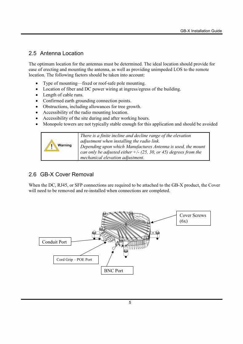
2.6 GB-X Cover Removal
When the DC, RJ45, or SFP connections are required to be attached to the GB-X product, the Cover
will need to be removed and re-installed when connections are completed.
Conduit Port
Cord Grip – POE Port
Cover Screws
(6x)
BNC Port
GB-X Installation Guide
6
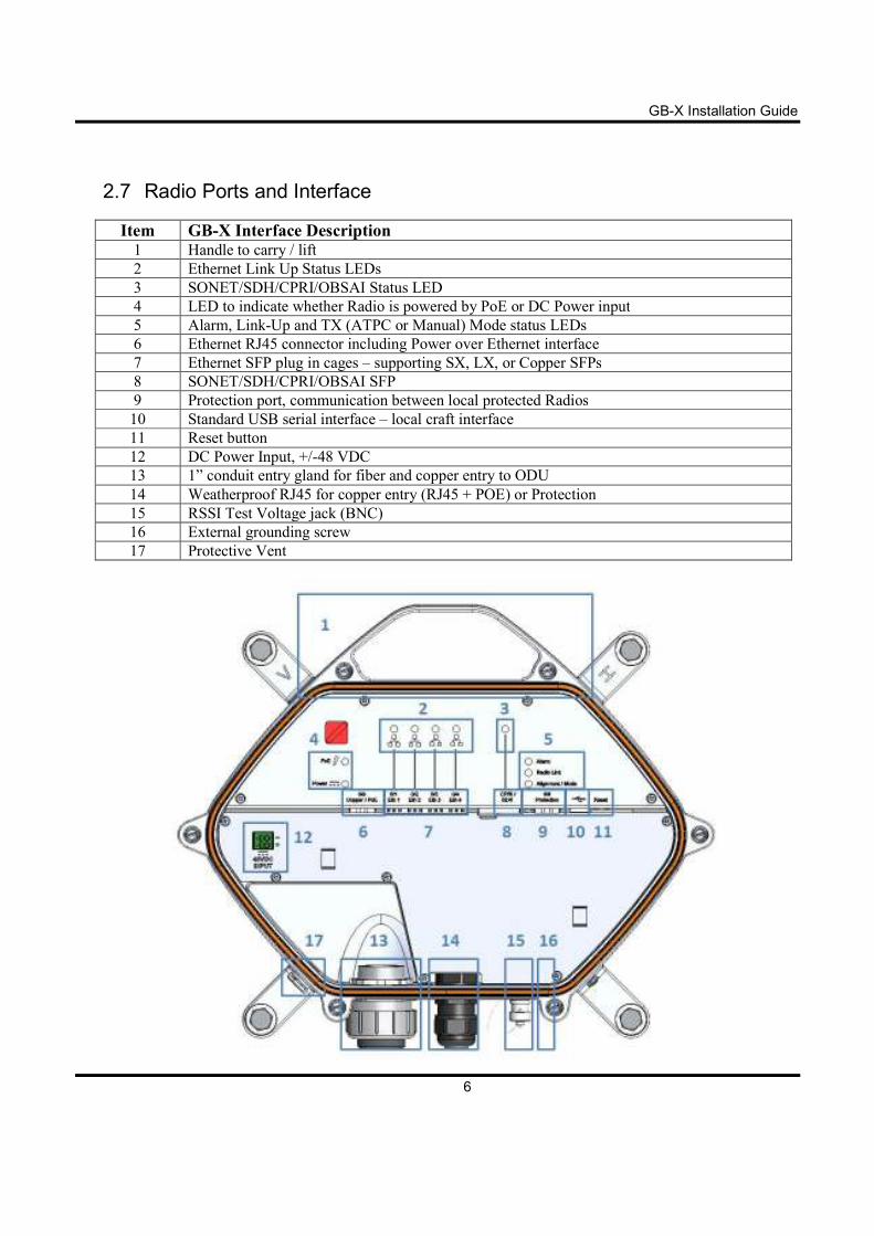
2.7 Radio Ports and Interface
Item GB-X Interface Description 1 Handle to carry / lift
2 Ethernet Link Up Status LEDs
3 SONET/SDH/CPRI/OBSAI Status LED
4 LED to indicate whether Radio is powered by PoE or DC Power input
5 Alarm, Link-Up and TX (ATPC or Manual) Mode status LEDs
6 Ethernet RJ45 connector including Power over Ethernet interface
7 Ethernet SFP plug in cages – supporting SX, LX, or Copper SFPs
8 SONET/SDH/CPRI/OBSAI SFP
9 Protection port, communication between local protected Radios
10 Standard USB serial interface – local craft interface
11 Reset button
12 DC Power Input, +/-48 VDC
13 1” conduit entry gland for fiber and copper entry to ODU
14 Weatherproof RJ45 for copper entry (RJ45 + POE) or Protection
15 RSSI Test Voltage jack (BNC)
16 External grounding screw
17 Protective Vent
GB-X Installation Guide
7
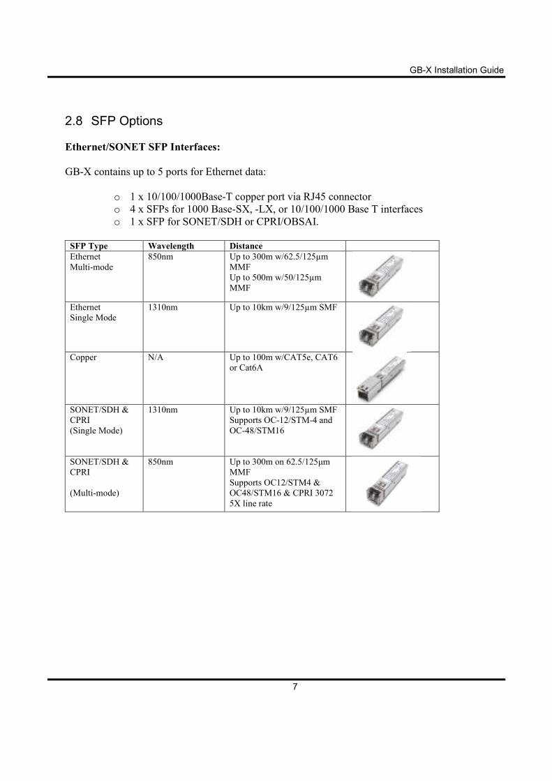
2.8 SFP Options
Ethernet/SONET SFP Interfaces:
GB-X contains up to 5 ports for Ethernet data:
o 1 x 10/100/1000Base-T copper port via RJ45 connector
o 4 x SFPs for 1000 Base-SX, -LX, or 10/100/1000 Base T interfaces
o 1 x SFP for SONET/SDH or CPRI/OBSAI.
SFP Type Wavelength Distance
Ethernet
Multi-mode
850nm Up to 300m w/62.5/125µm
MMF
Up to 500m w/50/125µm
MMF
Ethernet
Single Mode
1310nm Up to 10km w/9/125µm SMF
Copper N/A Up to 100m w/CAT5e, CAT6
or Cat6A
SONET/SDH &
CPRI
(Single Mode)
1310nm Up to 10km w/9/125µm SMF
Supports OC-12/STM-4 and
OC-48/STM16
SONET/SDH &
CPRI
(Multi-mode)
850nm Up to 300m on 62.5/125µm
MMF
Supports OC12/STM4 &
OC48/STM16 & CPRI 3072
5X line rate
GB-X Installation Guide
8
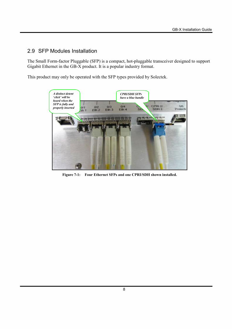
2.9 SFP Modules Installation
The Small Form-factor Pluggable (SFP) is a compact, hot-pluggable transceiver designed to support
Gigabit Ethernet in the GB-X product. It is a popular industry format.
This product may only be operated with the SFP types provided by Solectek.
Figure 7-1: Four Ethernet SFPs and one CPRI/SDH shown installed.
A distinct detent
‘click’ will be
heard when the
SFP is fully and
properly inserted
CPRI/SDH SFPs
have a blue handle
GB-X Installation Guide
9
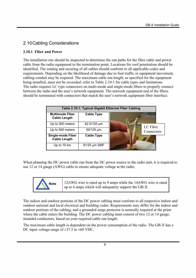
2.10 Cabling Considerations
2.10.1 Fiber and Power
The installation site should be inspected to determine the run paths for the fiber cable and power
cable from the radio equipment to the termination point. Locations for roof penetration should be
identified. The routing and securing of all cables should conform to all applicable codes and
requirements. Depending on the likelihood of damage due to foot traffic or equipment movement,
cabling conduit may be required. The maximum cable run length, as specified for the equipment
being installed, must not be exceeded: refer to Table 2.10-1 for cable types and limitations.
The radio requires LC type connectors on multi-mode and single-mode fibers to properly connect
between the radio and the user’s network equipment. The network equipment end of the fibers
should be terminated with connectors that match the user’s network equipment fiber interface.
Table 2.10-1: Typical Gigabit Ethernet Fiber Cabling
Multimode Fiber Cable Length
Cable Type
Up to 300 meters 62.5/125 µm
Up to 500 meters 50/125 µm
Single-mode Fiber Cable Length
Cable Type
Up to 10 km 9/125 µm SMF
When planning the DC power cable run from the DC power source to the radio unit, it is required to
use 12 or 14 gauge (AWG) cable to ensure adequate voltage at the radio.
12AWG wire is rated up to 9 amps while the 14AWG wire is rated
up to 6 amps which will adequately support the GB-X.
The indoor and outdoor portions of the DC power cabling must conform to all respective indoor and
outdoor national and local electrical and building codes. Requirements may differ for the indoor and
outdoor portions of the cabling, and a grounded surge protector is normally required at the point
where the cable enters the building. The DC power cabling must consist of two 12 or 14 gauge,
stranded conductors, based on your required cable run length.
The maximum cable length is dependent on the power consumption of the radio. The GB-X has a
DC input voltage range of ±37.5 to ±60 VDC.
LC Fiber
Connectors
GB-X Installation Guide
10
2.10.2 Integral PoE
The radio can accept DC power through the Copper 5 RJ45 connector to serve as a Power over
Ethernet (PoE) interface, and / or to the 2-pin DC/power connector (which bypasses the PoE
interface).
Use an outdoor (plenum) rated (weather-protected) Cat5e cable to connect the PoE enabled source to
the Copper 5 port on the radio via the RJ45 cordgrip gland on the radio. The cord grip gland shall be
tightened to (20 +/-2in.lbs.) if a cable is routed thru the cord grip gland.
The PoE connection can also be used as a power backup for the
DC power input. In this way, if a unit’s DC power fails, the unit
will switch to the PoE power source.
A service loop shall be created on the Cat5e cable and secured to a permanent location to ensure
sufficient cable length to enable the radio to be moved during service, prevent water from following
the Cat5e cable down to the PoE, junction box, or building entrance, and to prevent compromising
the Gland connection. A suggested length is 24 inches (60 cm) from the radio to the bottom of the
service loop.
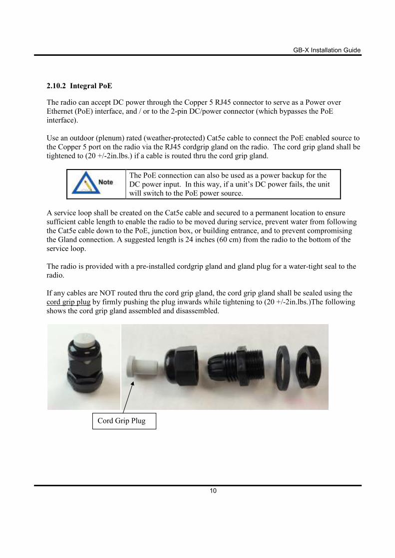
The radio is provided with a pre-installed cordgrip gland and gland plug for a water-tight seal to the
radio.
If any cables are NOT routed thru the cord grip gland, the cord grip gland shall be sealed using the
cord grip plug by firmly pushing the plug inwards while tightening to (20 +/-2in.lbs.)The following
shows the cord grip gland assembled and disassembled.
Cord Grip Plug
GB-X Installation Guide
11
2.10.3 Conduit
Conduit is recommended for enclosure of the fiber/copper and power cables as they enter the radio.
The conduit provides a water-tight seal to the radio, as well as any weather or physical protection
required by the cables.
The conduit should be flexible, waterproof, and non-metallic. An example of this is LIQUID-
TUFF™ UL Liquid tight Flexible Non-Metallic Conduit (Type LFNC-B) or equivalent.
Conduit should be 1 inch (25.4 mm) in diameter.
GB-X Installation Guide
12
Installation
Conduit installation is done along with power and fiber/copper cabling installation as needed.
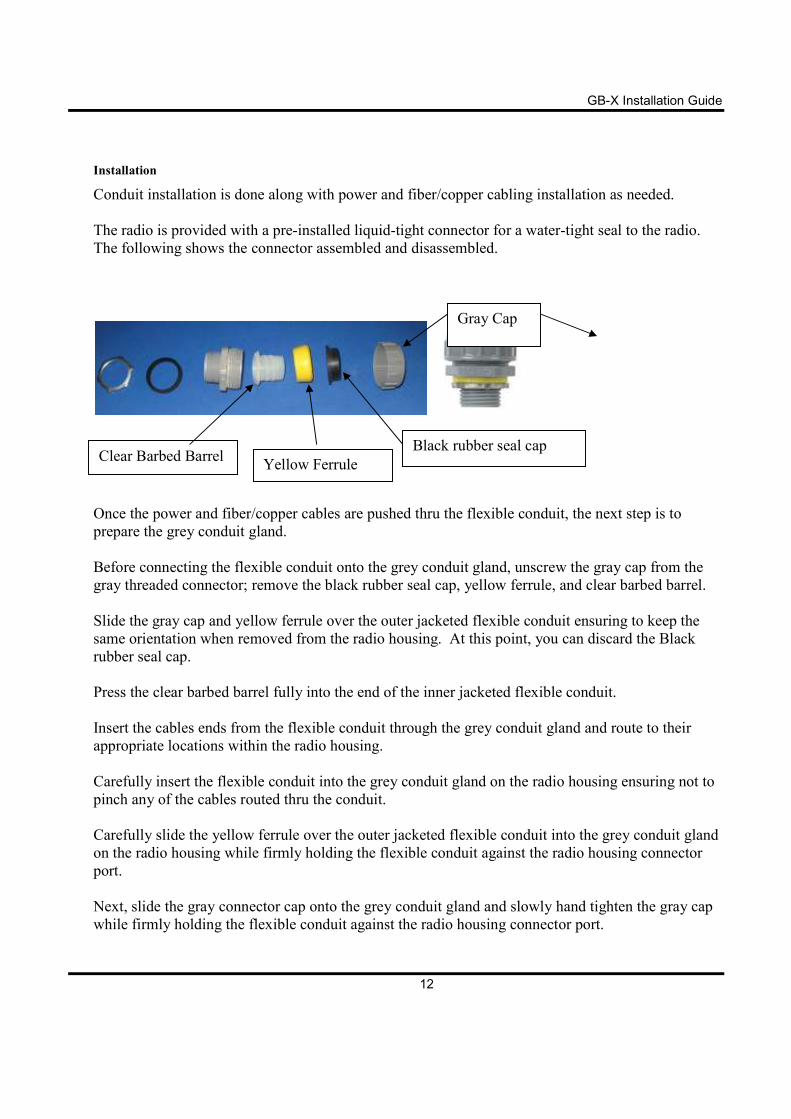
The radio is provided with a pre-installed liquid-tight connector for a water-tight seal to the radio.
The following shows the connector assembled and disassembled.
Once the power and fiber/copper cables are pushed thru the flexible conduit, the next step is to
prepare the grey conduit gland.
Before connecting the flexible conduit onto the grey conduit gland, unscrew the gray cap from the
gray threaded connector; remove the black rubber seal cap, yellow ferrule, and clear barbed barrel.
Slide the gray cap and yellow ferrule over the outer jacketed flexible conduit ensuring to keep the
same orientation when removed from the radio housing. At this point, you can discard the Black
rubber seal cap.
Press the clear barbed barrel fully into the end of the inner jacketed flexible conduit.
Insert the cables ends from the flexible conduit through the grey conduit gland and route to their
appropriate locations within the radio housing.
Carefully insert the flexible conduit into the grey conduit gland on the radio housing ensuring not to
pinch any of the cables routed thru the conduit.
Carefully slide the yellow ferrule over the outer jacketed flexible conduit into the grey conduit gland
on the radio housing while firmly holding the flexible conduit against the radio housing connector
port.
Next, slide the gray connector cap onto the grey conduit gland and slowly hand tighten the gray cap
while firmly holding the flexible conduit against the radio housing connector port.
Gray Cap
Black rubber seal cap
Yellow Ferrule Clear Barbed Barrel
As
compresses
barbed barrel
A service loop shall be created on the
sufficient cable length to enable the radio to be moved during service, prevent water from following
the conduit down to the junction box or building entrance, and to
connection. A suggested length is 24 inches (60 cm) from the radio to the bottom of the service
loop. The opposite end of the conduit is inserted into the cable tray if on a tower or onto the NEMA
or junction box.
13
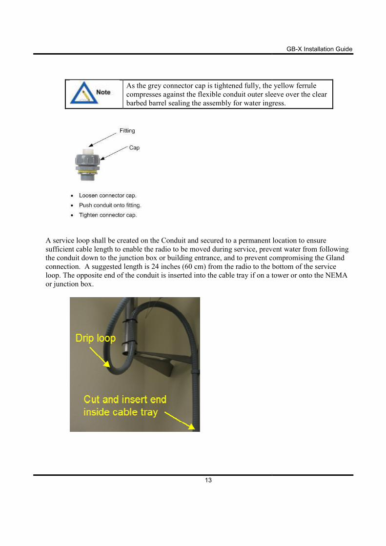
the grey connector cap is tightened fully, the
compresses against the flexible conduit outer sleeve over the clear
barbed barrel sealing the assembly for water ingress.
ervice loop shall be created on the Conduit and secured to a permanent location
sufficient cable length to enable the radio to be moved during service, prevent water from following
down to the junction box or building entrance, and to prevent compromising the Gland
connection. A suggested length is 24 inches (60 cm) from the radio to the bottom of the service
The opposite end of the conduit is inserted into the cable tray if on a tower or onto the NEMA
GB-X Installation Guide
the yellow ferrule
flexible conduit outer sleeve over the clear
sealing the assembly for water ingress.
and secured to a permanent location to ensure
sufficient cable length to enable the radio to be moved during service, prevent water from following
prevent compromising the Gland
connection. A suggested length is 24 inches (60 cm) from the radio to the bottom of the service
The opposite end of the conduit is inserted into the cable tray if on a tower or onto the NEMA
GB-X Installation Guide
14
The first tie provides the first anchor and strain relief. Gentle curves provide the necessary radius for
the fiber to minimize signal loss and eliminate sharp angles lessening voltage potential from being
induced during lightning storms.
With a short conduit, the radio's opening has been moved further away and moisture is unable to
migrate into the radio.
Tower Installation
Secure the conduit with suitable braces to ensure long-term performance. The total length of the
conduit should be a minimum of 10 feet (3 meters), but the length required to reach the cable tray is
site-specific.
Once the cables are installed, seal the conduit opening for additional protection from insects using
amalgamated tape or sealant.
All cables used should be outdoor-rated.
Below the conduit, secure the cables approximately every 1.6 feet (1/2 meter) onto the tower's cable
tray. Running the cables to the cable tray is recommended to provide additional environmental
protection.
Roof-Top Installation
Secure the conduit with suitable braces to ensure long-term performance. Terminate the network end
of the conduit into a NEMA enclosure or junction box. Terminate the conduit at the NEMA
enclosure by either:
• Drilling a hole in the bottom of the NEMA box for the fitting; or
• Removing one of the built-in conduit punch-outs if provided on the NEMA box.
Use amalgamated tape or sealant to create a watertight seal at that junction.
GB-X Installation Guide
15
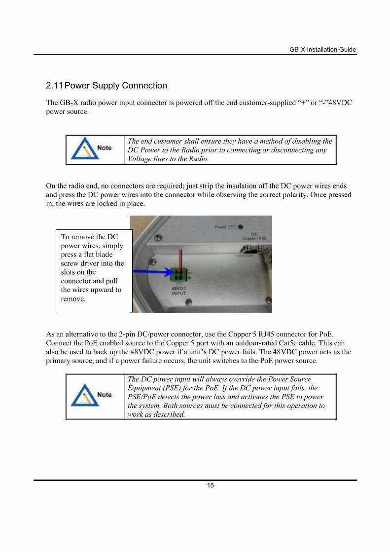
2.11 Power Supply Connection
The GB-X radio power input connector is powered off the end customer-supplied “+” or “-”48VDC
power source.
The end customer shall ensure they have a method of disabling the
DC Power to the Radio prior to connecting or disconnecting any
Voltage lines to the Radio.
On the radio end, no connectors are required; just strip the insulation off the DC power wires ends
and press the DC power wires into the connector while observing the correct polarity. Once pressed
in, the wires are locked in place.
As an alternative to the 2-pin DC/power connector, use the Copper 5 RJ45 connector for PoE.
Connect the PoE enabled source to the Copper 5 port with an outdoor-rated Cat5e cable. This can
also be used to back up the 48VDC power if a unit’s DC power fails. The 48VDC power acts as the
primary source, and if a power failure occurs, the unit switches to the PoE power source.
The DC power input will always override the Power Source
Equipment (PSE) for the PoE. If the DC power input fails, the
PSE/PoE detects the power loss and activates the PSE to power
the system. Both sources must be connected for this operation to
work as described.
To remove the DC
power wires, simply
press a flat blade
screw driver into the
slots on the
connector and pull
the wires upward to
remove.
GB-X Installation Guide
16
2.12 Grounding & Lightning
Proper grounding of the outdoor equipment reduces
electromagnetic interference, provides lightning protection, and
protects against electrical discharge.
Using improper techniques in lightning-prone geographic areas
may pose a danger to local personnel.
The source and connection points for the building-to-earth
ground in the vicinity of the antenna location should be
determined.
Customers can add addition surge protection to the DC electrical cables by adding a surge
suppressor. The surge suppressor should be installed before entry point where the DC electrical
cables exit/enter the building. Please review your local electrical codes.
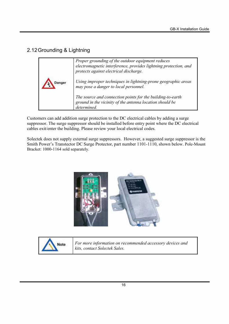
Solectek does not supply external surge suppressors. However, a suggested surge suppressor is the
Smith Power’s Transtector DC Surge Protector, part number 1101-1110, shown below. Pole-Mount
Bracket: 1000-1164 sold separately.
For more information on recommended accessory devices and
kits, contact Solectek Sales.
GB-X Installation Guide
17
2.13 Environmental
The structure to which the equipment will be mounted should be adequate to bear all wind and
weather conditions. The environmental conditions at the location must conform to the operating
environment specified for the equipment.
Operating Temperature: -33ºC to +55ºC (-27ºF to +131ºF) per EN 300 019-2-4
Humidity: 100% all-weather operation
Operating Altitude: Up to 4,500m (14,764ft)
Water Ingress: IP66
Wind Loading: 90 MPH operational, 125 MPH survival
GB-X Installation Guide
18
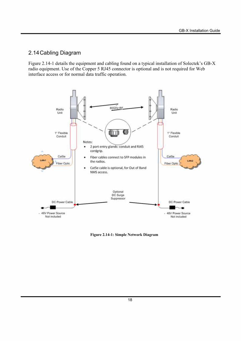
2.14 Cabling Diagram
Figure 2.14-1 details the equipment and cabling found on a typical installation of Solectek’s GB-X
radio equipment. Use of the Copper 5 RJ45 connector is optional and is not required for Web
interface access or for normal data traffic operation.
Figure 2.14-1: Simple Network Diagram
GB-X Installation Guide
19
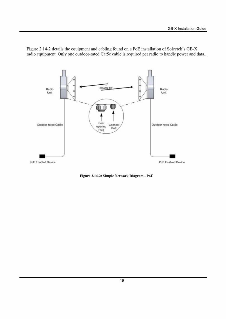
Figure 2.14-2 details the equipment and cabling found on a PoE installation of Solectek’s GB-X
radio equipment. Only one outdoor-rated Cat5e cable is required per radio to handle power and data..
Figure 2.14-2: Simple Network Diagram - PoE
GB-X Installation Guide
20
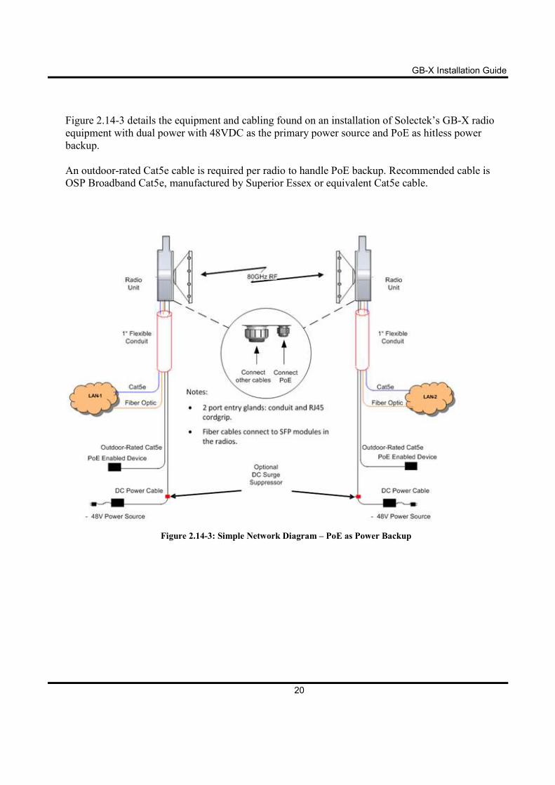
Figure 2.14-3 details the equipment and cabling found on an installation of Solectek’s GB-X radio
equipment with dual power with 48VDC as the primary power source and PoE as hitless power
backup.
An outdoor-rated Cat5e cable is required per radio to handle PoE backup. Recommended cable is
OSP Broadband Cat5e, manufactured by Superior Essex or equivalent Cat5e cable.
Figure 2.14-3: Simple Network Diagram – PoE as Power Backup
GB-X Installation Guide
21
3 Installation
3.1 General
It is recommended that installation personnel read this section in its entirety prior to installing the
Solectek system. During a particular phase of installation, the user may refer directly to the
applicable subsection.
The Installation section is comprised of the following subsections covering the procedures and
guidelines for installing the Solectek radio system.
3.2 Equipment Unpacking
The radio system equipment will arrive in four boxes—two boxes for the two antenna and mounting
kits and two boxes containing the radio unit (one low-band and one high-band). Locate the correct
box (low band or high band) before beginning installation by checking the label on the outside of the
box or on the radio itself. It is recommended that the shipping cartons and packing materials be
retained in the event that it is necessary to return any equipment.
GB-X Installation Guide
22
3.3 Installation Tools
The following tools are required for installing the radio and the antenna:
• Torque Driver (0-25 in. lbs.) for GB-X unit for the following items:
� Open-end wrench 1/2 (Cover Screws)
� Open-end wrench 8mm or 5/16 (Chassis Earth Ground Connection)
� Open-end wrench 7/8 (Cord Grip Connector)
• Open-end wrench 9/16 inch (Radio to Antenna Screws)
• Open-end wrench 1/2 inch (Various locations)
• Ratchet with 6inch extension and 9/16 inch deep socket (Radio to Antenna Screws)
• Wire stripper/cutter/crimp tool (10-16 gauge)
• Electrical tape
• Fish tape (draw wire) for pulling cable
• Cable tie wraps
• Hand-held digital voltmeter (DVM) with standard banana-plug receptacles
• Allen wrench 3/16 inch (depending upon Antenna Manufacturer, maybe be supplied with
Antenna)
• Signaling mirror (optional)
• DOW Corning 111 Valve Lubricant & Sealant or equivalent (for antenna O-ring gasket)
GB-X Installation Guide
23
3.3 Antenna Mount Installation
For antenna mount installation instructions, please refer to your antenna manufacturer’s installation
guide to perform the following:
1. Assemble the antenna mounting hardware.
2. Mount the antenna to the mast.
Read these instructions before beginning installation. Caution
should be used. Qualified persons experienced with antenna
assembly and installation are required for installation.
Solectek disclaims any responsibility or liability for damage or
injury resulting from incorrect or unsafe installation practices.
The antenna has been formed to a very close tolerance parabolic
shape. Careful handling and assembly is required to avoid
denting the reflector, which would degrade antenna performance.
When using the left-side radio mount position, the antenna gets
rotated by 180 degrees. The drain hole must be open at the
bottom and closed off at the top of the antenna to prevent water
ingress.
3.4 Antenna and Radio Installation
It is critically important during installation to ensure the
radios on each side of the link are in the same polarization
(horizontal-horizontal or vertical-vertical). A link that has a
radio on one side of the link set in the horizontal polarization,
and the other side of the link set in the vertical polarization,
will not operate properly.
It is also critically important that a high-band radio is paired with
a low-band radio to ensure the system will operate properly.
Prior to installation, check each radio to verify one is a high-
band and the other is a low-band version. The label on the radio
will indicate the band (blue for high or red for low).
GB-X Installation Guide
24
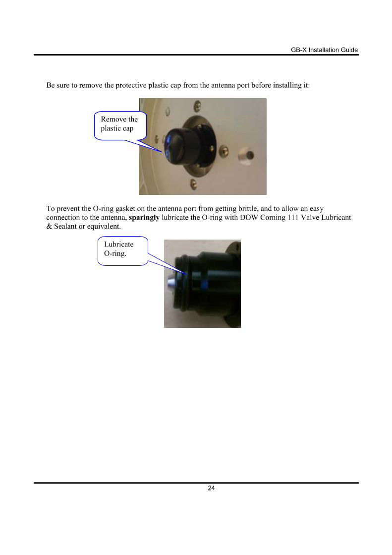
Be sure to remove the protective plastic cap from the antenna port before installing it:
To prevent the O-ring gasket on the antenna port from getting brittle, and to allow an easy
connection to the antenna, sparingly lubricate the O-ring with DOW Corning 111 Valve Lubricant
& Sealant or equivalent.
Remove the
plastic cap
Lubricate
O-ring.
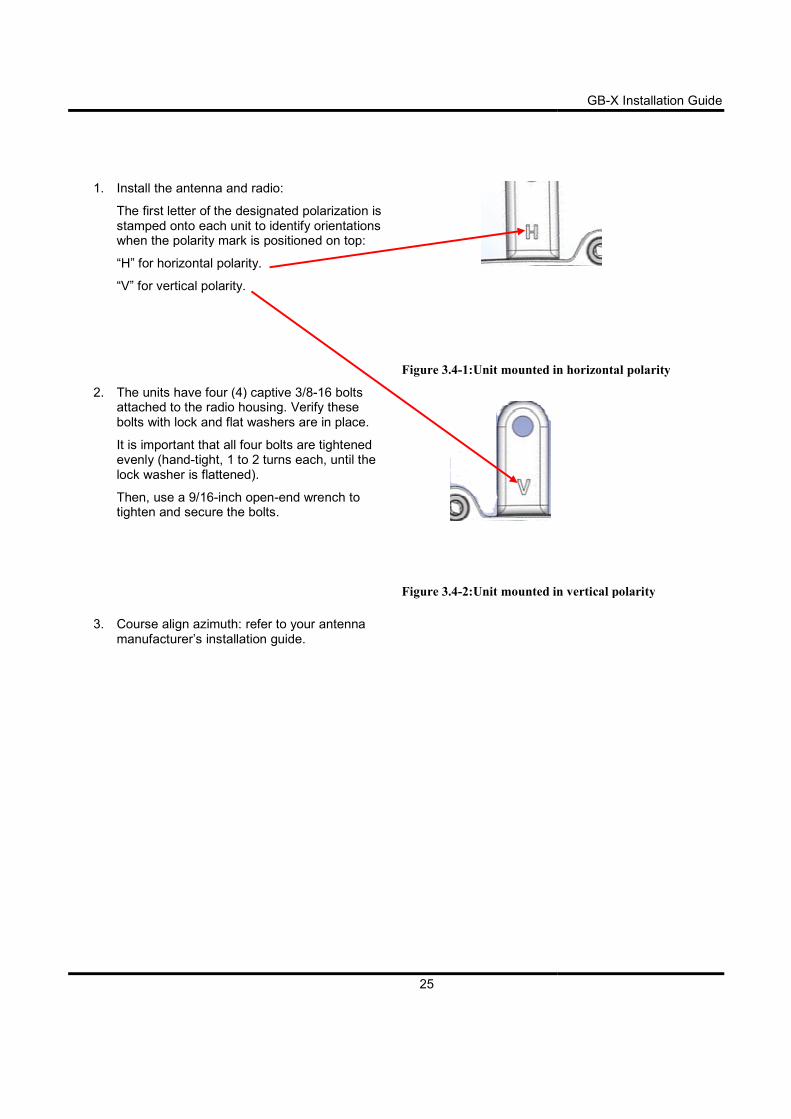
1. Install the antenna and radio:
The first letter of the designated polarization is stamped onto each unit to identify orientatiwhen the polarity mark is positioned on top:
“H” for horizontal polarity.
“V” for vertical polarity.
2. The units have four (4) captive 3/8attached to the radio housing. Verify these bolts with lock and flat washer
It is important that all four bolts are tightened evenly (hand-tight, 1 to 2 turns eachlock washer is flattened).
Then, use a 9/16-inch open-end wrench to tighten and secure the bolts.
3. Course align azimuth: refer to your antenna manufacturer’s installation guide.
25
antenna and radio:
The first letter of the designated polarization is stamped onto each unit to identify orientations when the polarity mark is positioned on top:
Figure 3.4-1:Unit mounted in horizontal polarity
four (4) captive 3/8-16 bolts hed to the radio housing. Verify these
bolts with lock and flat washers are in place.
It is important that all four bolts are tightened tight, 1 to 2 turns each, until the
end wrench to .
Figure 3.4-2:Unit mounted in vertical polarity
: refer to your antenna
manufacturer’s installation guide.
GB-X Installation Guide
:Unit mounted in horizontal polarity
mounted in vertical polarity
3.5 Cable Installation
3.5.1 Fiber Cabling
1. Install the desired SFP modules in the radio with duplex MMF or SMF fiber from the radio to the
network termination equipment (switch or router with 1000Base
looped around the inside of the enclosure to provide strain
The connectors on the radio end of the fiber require a duplex LC connector; the connectors on
the switch/router end should mate to the network equipment.
2. Connect fibers at the network equipment.
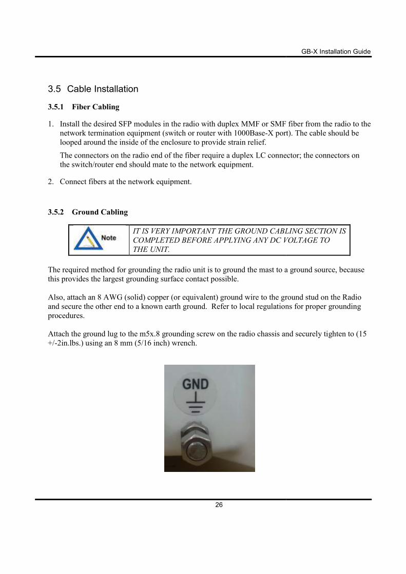
3.5.2 Ground Cabling
IT IS VERY IMPORTANT TH
COMPLETED BEFORE APPLYING ANY DC VOLTAGE TO
THE UNIT.
The required method for grounding the radio unit is to ground the mast to a ground source, because
this provides the largest grounding surface contact possible.
Also, attach an 8 AWG (solid) copper (or equivalent) ground wire to the ground stud on the Radio
and secure the other end to a known earth ground.
procedures.
Attach the ground lug to the m5x.8 grounding screw on the radio chassis
+/-2in.lbs.) using an 8 mm (5/16 inch) wrench.
26
Install the desired SFP modules in the radio with duplex MMF or SMF fiber from the radio to the
network termination equipment (switch or router with 1000Base-X port). The cable should be
looped around the inside of the enclosure to provide strain relief.
The connectors on the radio end of the fiber require a duplex LC connector; the connectors on
the switch/router end should mate to the network equipment.
Connect fibers at the network equipment.
IT IS VERY IMPORTANT THE GROUND CABLING
COMPLETED BEFORE APPLYING ANY DC VOLTAGE TO
THE UNIT.
The required method for grounding the radio unit is to ground the mast to a ground source, because
this provides the largest grounding surface contact possible.
lid) copper (or equivalent) ground wire to the ground stud on the Radio
and secure the other end to a known earth ground. Refer to local regulations for proper grounding
Attach the ground lug to the m5x.8 grounding screw on the radio chassis and securely
using an 8 mm (5/16 inch) wrench.
GB-X Installation Guide
Install the desired SFP modules in the radio with duplex MMF or SMF fiber from the radio to the
X port). The cable should be
The connectors on the radio end of the fiber require a duplex LC connector; the connectors on
E GROUND CABLING SECTION IS
COMPLETED BEFORE APPLYING ANY DC VOLTAGE TO
The required method for grounding the radio unit is to ground the mast to a ground source, because
lid) copper (or equivalent) ground wire to the ground stud on the Radio
Refer to local regulations for proper grounding
and securely tighten to (15
GB-X Installation Guide
27
3.5.3 Power Cabling
1. Ensure the DC wire used is two-pair 12 gauge or 14 gauge, and ensure the cable length is
appropriate for the power consumption of the radio.
2. Install the DC power cable and attach it to the primary power source. Do not connect the power
wires to the radio at this time. If a PoE will not be used, then connect the DC Input voltage
lines (two-pair 12 gauge or 14 gauge wires) to power up the Radio.
3. Inserting a small screwdriver or blade tool into the slot on the DC connector will hold open the
connectors for wire insertion. (The tool can also be used to hold open the connector to release
the wire.)
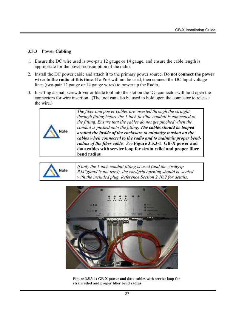
The fiber and power cables are inserted through the straight-
through fitting before the 1 inch flexible conduit is connected to
the fitting. Ensure that the cables do not get pinched when the
conduit is pushed onto the fitting. The cables should be looped
around the inside of the enclosure to minimize tension on the
cables when connected to the radio and to maintain proper bend-
radius of the fiber cable. See Figure 3.5.3-1: GB-X power and
data cables with service loop for strain relief and proper fiber
bend radius
If only the 1 inch conduit fitting is used (and the cordgrip
RJ45gland is not used), the cordgrip opening should be sealed
with the included plug. Reference Section 2.10.2 for details.
Figure 3.5.3-1: GB-X power and data cables with service loop for
strain relief and proper fiber bend radius
GB-X Installation Guide
28
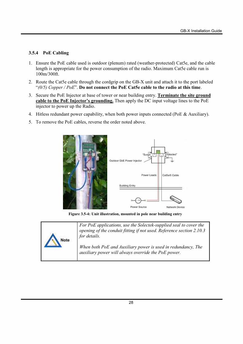
3.5.4 PoE Cabling
1. Ensure the PoE cable used is outdoor (plenum) rated (weather-protected) Cat5e, and the cable
length is appropriate for the power consumption of the radio. Maximum Cat5e cable run is
100m/300ft.
2. Route the Cat5e cable through the cordgrip on the GB-X unit and attach it to the port labeled
“(0/5) Copper / PoE”. Do not connect the PoE Cat5e cable to the radio at this time.
3. Secure the PoE Injector at base of tower or near building entry. Terminate the site ground
cable to the PoE Injector’s grounding. Then apply the DC input voltage lines to the PoE
injector to power up the Radio.
4. Hitless redundant power capability, when both power inputs connected (PoE & Auxiliary).
5. To remove the PoE cables, reverse the order noted above.
Figure 3.5-4: Unit illustration, mounted in pole near building entry
For PoE applications, use the Solectek-supplied seal to cover the
opening of the conduit fitting if not used. Reference section 2.10.3
for details.
When both PoE and Auxiliary power is used in redundancy, The
auxiliary power will always override the PoE power.
GB-X Installation Guide
29
3.5.5 10/100/1000 Base-T Surge Suppressor
The GB-X radio internally contains an Ethernet-rated surge suppressor within the RJ-45 copper
interfaces of the unit.
A surge suppressor should also be used at the point where the cable enters a building or is connected
to other outdoor equipment that does not already contain surge-suppression hardware.
If the 10/100/1000Base-T port is permanently connected to other network equipment (not normally
required), it should be connected using Cat5e UTP cables rated for the outdoor and/or indoor
environments where the cables will be run.
Failure to install surge suppression hardware on the UTP cable
at the building’s point-of-entry can expose the radio and network
equipment to electrical surges due to lightning strike or other
phenomena. Such electrical surges could cause irreparable
damage to the radio and/or network equipment not covered by the
manufacturer’s warranty.
GB-X Installation Guide
30
3.6 Antenna Alignment
3.6.1 Initial Equipment Checks and Configuration
1. Finish the installation, as described in the previous sections.
2. Inspect the radio polarization. Confirm that the polarity matches the site design and license. Both
ends of the link must have the same polarity.
3. Connect DC power or PoE to the radio. If DC power is connected, verify that the Power LED is
lit solid green. If PoE is connected, verify that the PoE LED is lit solid green.
4. Log into the GB-X Web interface and go to the Radio Link page. Configure the following
parameters in the following order:
• Link ID – Set to a value that matches at both ends of the link.
• Rate – Set to the desired channel bandwidth and modulation per the link design.
• Transmitter – Set to Enable.
• Transmit Channel – Set the channel to the frequency specified in the link design or
site license.
• ATPC Mode – Set to Manual. The Max TX Power parameter will then be
configurable. This also prevents the transmitter from adjusting while the far-end
receiver is being aligned.
• Max TX Power – Set to the maximum allowable power specified in the site design or
site license.
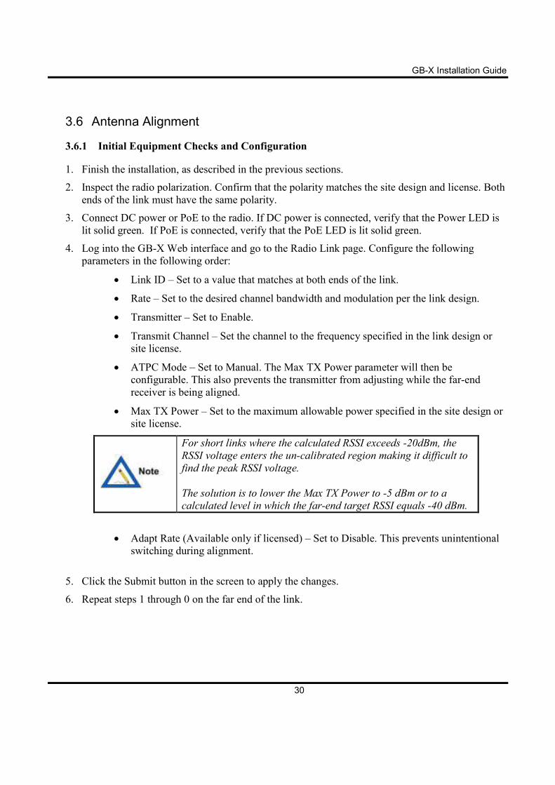
For short links where the calculated RSSI exceeds -20dBm, the
RSSI voltage enters the un-calibrated region making it difficult to
find the peak RSSI voltage.
The solution is to lower the Max TX Power to -5 dBm or to a
calculated level in which the far-end target RSSI equals -40 dBm.
• Adapt Rate (Available only if licensed) – Set to Disable. This prevents unintentional
switching during alignment.
5. Click the Submit button in the screen to apply the changes.
6. Repeat steps 1 through 0 on the far end of the link.
GB-X Installation Guide
31
3.6.2 Prepare to Coarse-Align Radio
1. Using the graph in Appendix B, determine the target RSSI voltage based on the target receive
level in dBm established by the link design or site license.
The target RSSI should be adjusted accordingly if the transmitter
power was reduced for alignment purposes due to short path
distance.
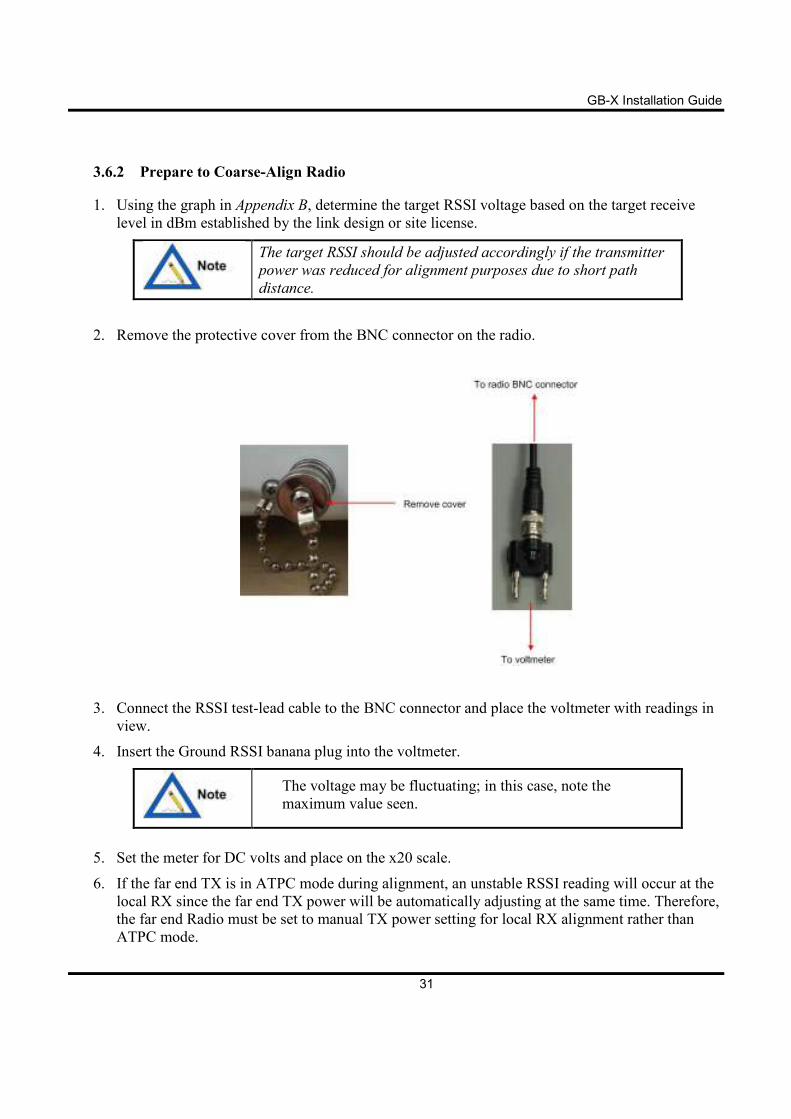
2. Remove the protective cover from the BNC connector on the radio.
3. Connect the RSSI test-lead cable to the BNC connector and place the voltmeter with readings in
view.
4. Insert the Ground RSSI banana plug into the voltmeter.
The voltage may be fluctuating; in this case, note the
maximum value seen.
5. Set the meter for DC volts and place on the x20 scale.
6. If the far end TX is in ATPC mode during alignment, an unstable RSSI reading will occur at the
local RX since the far end TX power will be automatically adjusting at the same time. Therefore,
the far end Radio must be set to manual TX power setting for local RX alignment rather than
ATPC mode.
GB-X Installation Guide
32
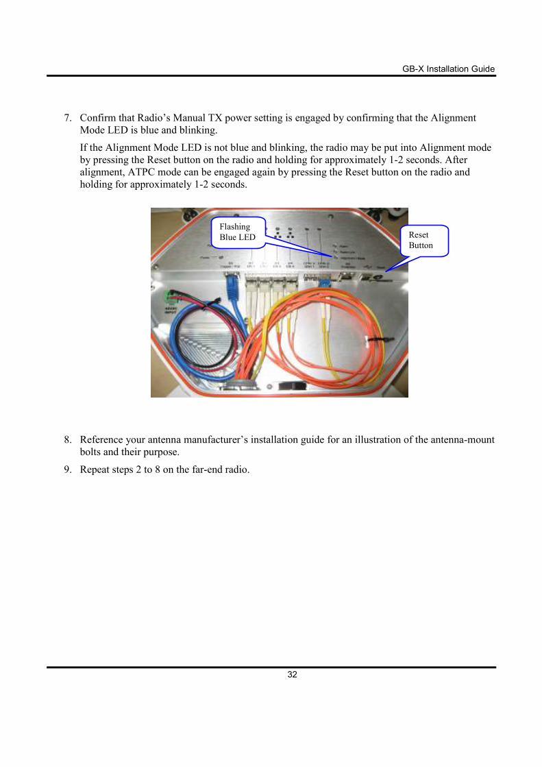
7. Confirm that Radio’s Manual TX power setting is engaged by confirming that the Alignment
Mode LED is blue and blinking.
If the Alignment Mode LED is not blue and blinking, the radio may be put into Alignment mode
by pressing the Reset button on the radio and holding for approximately 1-2 seconds. After
alignment, ATPC mode can be engaged again by pressing the Reset button on the radio and
holding for approximately 1-2 seconds.
8. Reference your antenna manufacturer’s installation guide for an illustration of the antenna-mount
bolts and their purpose.
9. Repeat steps 2 to 8 on the far-end radio.
Reset
Button
Flashing
Blue LED
GB-X Installation Guide
33
3.6.3 Coarse-Align Radio Antennas
1. Using the graph in Appendix B, become familiar with how the RSSI voltage corresponds to
stronger or weaker Receive Signal Strengths.
2. Set the radio terminal to the pre-defined azimuth if available. If not, use binoculars or a signal
mirror to locate the far-end radio location.
3. If you can see the far-end radio terminal, estimate the alignment visually and tighten the pole
mount brackets with the fine-adjustment bolt set to the middle of the adjustment range.
4. Ensure the horizontal adjustment bolts are snug; only tighten the bolts one quarter of a turn.
5. Slightly rotate each antenna up or down for best vertical alignment, and left or right for best
horizontal alignment, by finding the strongest RSSI voltage reading.
6. To ensure that the antennas are not aligned on a side lobe, they must be rotated about 7 to 10
degrees on each side of the perceived alignment center to ensure that the true strongest RSSI
voltage is found.
The width of the center beam is only 0.4º (2 foot antenna) or 0.9º
(1 foot antenna), and the first side-lobe beam is only 1 degree off
from center.
Set the antenna in the position resulting in the strongest RSSI voltage reading.
7. Repeat these steps on the far-end radio.
GB-X Installation Guide
34
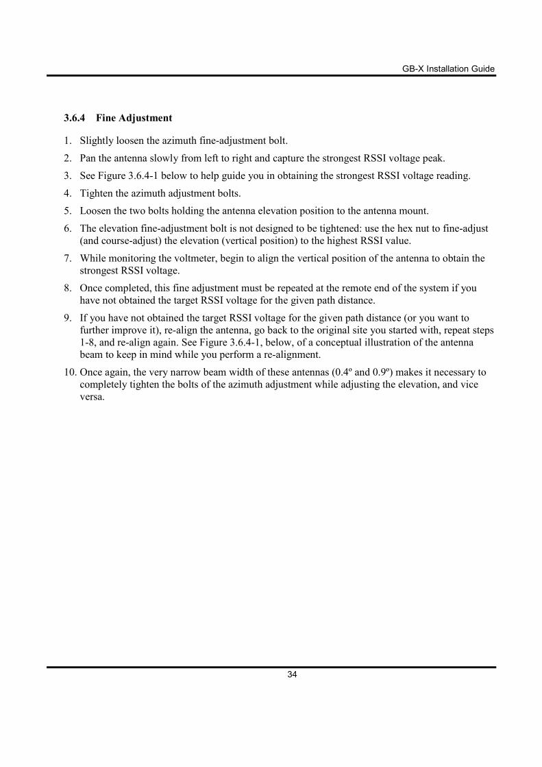
3.6.4 Fine Adjustment
1. Slightly loosen the azimuth fine-adjustment bolt.
2. Pan the antenna slowly from left to right and capture the strongest RSSI voltage peak.
3. See Figure 3.6.4-1 below to help guide you in obtaining the strongest RSSI voltage reading.
4. Tighten the azimuth adjustment bolts.
5. Loosen the two bolts holding the antenna elevation position to the antenna mount.
6. The elevation fine-adjustment bolt is not designed to be tightened: use the hex nut to fine-adjust
(and course-adjust) the elevation (vertical position) to the highest RSSI value.
7. While monitoring the voltmeter, begin to align the vertical position of the antenna to obtain the
strongest RSSI voltage.
8. Once completed, this fine adjustment must be repeated at the remote end of the system if you
have not obtained the target RSSI voltage for the given path distance.
9. If you have not obtained the target RSSI voltage for the given path distance (or you want to
further improve it), re-align the antenna, go back to the original site you started with, repeat steps
1-8, and re-align again. See Figure 3.6.4-1, below, of a conceptual illustration of the antenna
beam to keep in mind while you perform a re-alignment.
10. Once again, the very narrow beam width of these antennas (0.4º and 0.9º) makes it necessary to
completely tighten the bolts of the azimuth adjustment while adjusting the elevation, and vice
versa.
GB-X Installation Guide
35
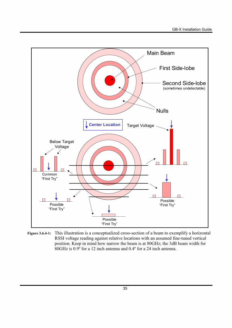
Figure 3.6.4-1: This illustration is a conceptualized cross-section of a beam to exemplify a horizontal
RSSI voltage reading against relative locations with an assumed fine-tuned vertical
position. Keep in mind how narrow the beam is at 80GHz; the 3dB beam width for
80GHz is 0.9º for a 12 inch antenna and 0.4º for a 24 inch antenna.
Target Voltage
Possible
“First Try”
Common
“First Try”
Below Target
Voltage
Possible
“First Try”
Center Location
Possible
“First Try”
Main Beam
First Side-lobe
Second Side-lobe(sometimes undetectable)
Nulls
GB-X Installation Guide
36
3.6.5 Locking Down Radio Antennas
1. After the target RSSI voltage has been achieved, ensure all bolts are tightened evenly and
securely, and ensure the RSSI voltage remains unchanged after tightening is completed.
2. Always evenly tighten the bolts in small fractions at a time to ensure minimum change to your
completed alignment.
3.6.6 Final Configuration
1. Log into the GB-X Web interface and go to the Radio Link page.
2. Set the Power Output level to the value specified in the link design or site license and click
Submit to apply the changes. This should only be required if the power level was intentionally
reduced for alignment on short distance paths.
3. Go to the Maintenance page and click the Commit Configuration button.
4. Perform steps 1 – 3at both ends of the link.
GB-X Installation Guide
37
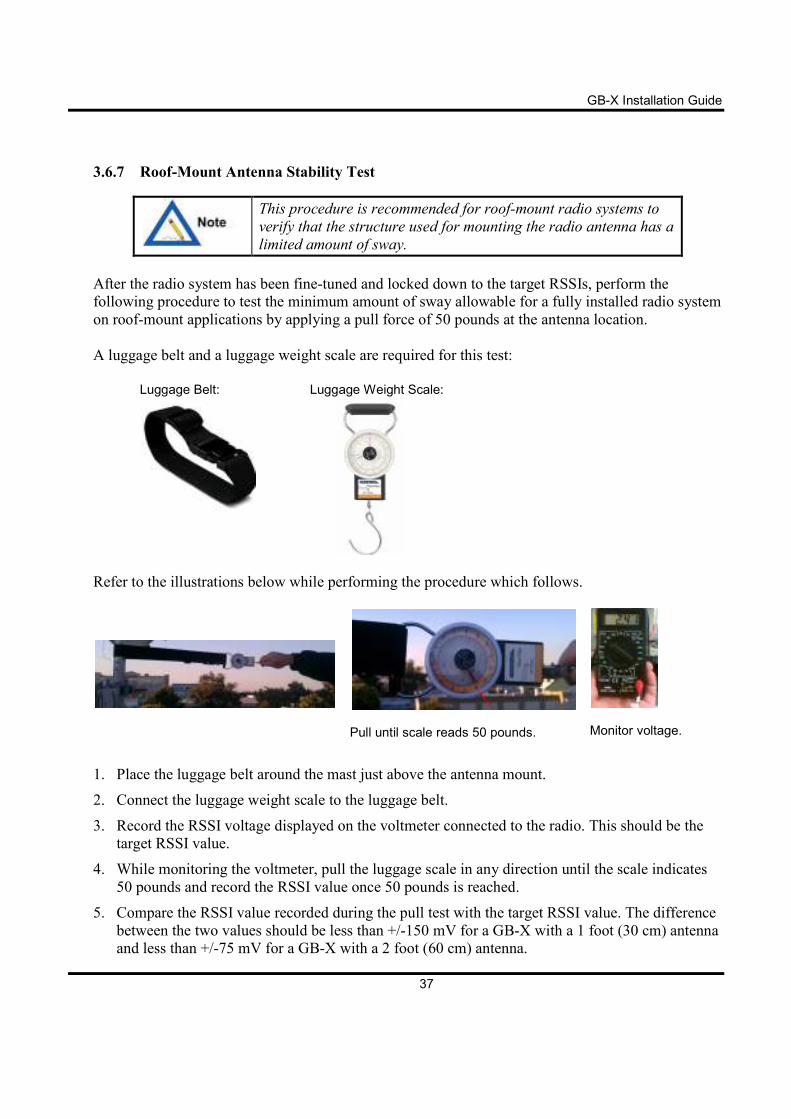
3.6.7 Roof-Mount Antenna Stability Test
This procedure is recommended for roof-mount radio systems to
verify that the structure used for mounting the radio antenna has a
limited amount of sway.
After the radio system has been fine-tuned and locked down to the target RSSIs, perform the
following procedure to test the minimum amount of sway allowable for a fully installed radio system
on roof-mount applications by applying a pull force of 50 pounds at the antenna location.
A luggage belt and a luggage weight scale are required for this test:
Luggage Belt: Luggage Weight Scale:
Refer to the illustrations below while performing the procedure which follows.
Pull until scale reads 50 pounds.
Monitor voltage.
1. Place the luggage belt around the mast just above the antenna mount.
2. Connect the luggage weight scale to the luggage belt.
3. Record the RSSI voltage displayed on the voltmeter connected to the radio. This should be the
target RSSI value.
4. While monitoring the voltmeter, pull the luggage scale in any direction until the scale indicates
50 pounds and record the RSSI value once 50 pounds is reached.
5. Compare the RSSI value recorded during the pull test with the target RSSI value. The difference
between the two values should be less than +/-150 mV for a GB-X with a 1 foot (30 cm) antenna
and less than +/-75 mV for a GB-X with a 2 foot (60 cm) antenna.
GB-X Installation Guide
38
6. Remove the test cable from the radio and replace the BNC connector cover.
Failure to re-install the BNC Connector cover could cause
environmental issues with the Radio which would not be covered
under the manufactures warranty.
7. The installation is now complete.
The most important alignment technique is care and patience! It is
recommended that these models be aligned with personnel present
at both ends of the link, and the installers should allow 90 minutes
to optimally align these units.
GB-X Installation Guide
39
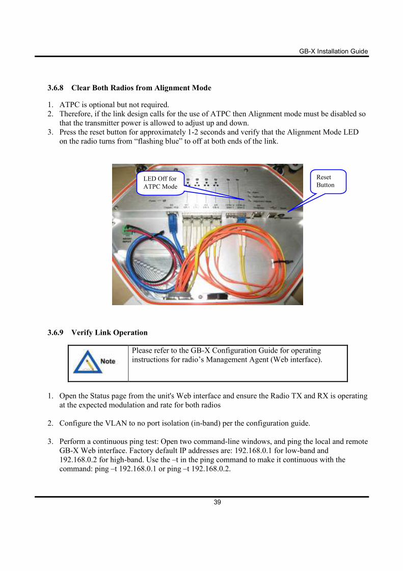
3.6.8 Clear Both Radios from Alignment Mode
1. ATPC is optional but not required.
2. Therefore, if the link design calls for the use of ATPC then Alignment mode must be disabled so
that the transmitter power is allowed to adjust up and down.
3. Press the reset button for approximately 1-2 seconds and verify that the Alignment Mode LED
on the radio turns from “flashing blue” to off at both ends of the link.
3.6.9 Verify Link Operation
Please refer to the GB-X Configuration Guide for operating
instructions for radio’s Management Agent (Web interface).
1. Open the Status page from the unit's Web interface and ensure the Radio TX and RX is operating
at the expected modulation and rate for both radios
2. Configure the VLAN to no port isolation (in-band) per the configuration guide.
3. Perform a continuous ping test: Open two command-line windows, and ping the local and remote
GB-X Web interface. Factory default IP addresses are: 192.168.0.1 for low-band and
192.168.0.2 for high-band. Use the –t in the ping command to make it continuous with the
command: ping –t 192.168.0.1 or ping –t 192.168.0.2.
Reset
Button LED Off for
ATPC Mode
GB-X Installation Guide
40
4. Perform the continuous ping test at both ends. Wait a few minutes; ensure you are getting
responses from the local and remote Web interface.
5. Go to the Statistics page and reset the statistics for each radio end. There will be a small amount
of traffic from the continuous ping test.
6. Review the Statistics page results; ensure packets are being transmitted and received, and there
are no excessive error conditions.
GB-X Installation Guide
41
4 Radio Link Status Indicators
4.1 Normal Operation
During normal operation, the following conditions should exist at the radio:
• The Power LED or the PoE LED should be lit - solid green.
• The Alignment Mode LED should be OFF.
• The Radio Link LED should be lit—solid green.
• The Alarm LED should be lit—solid green.
The GB-X system does not require periodic maintenance. However, each end of the link should be
periodically inspected for visible damage or excessive accumulation of dirt on the antenna’s radome.
GB-X Installation Guide
42
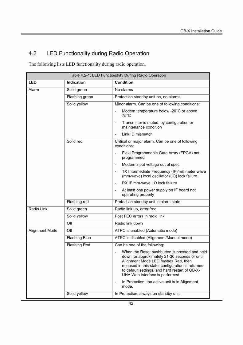
4.2 LED Functionality during Radio Operation
The following lists LED functionality during radio operation.
Table 4.2-1: LED Functionality During Radio Operation
LED Indication Condition
Alarm Solid green No alarms
Flashing green Protection standby unit on, no alarms
Solid yellow Minor alarm. Can be one of following conditions:
- Modem temperature below -20°C or above 75°C
- Transmitter is muted, by configuration or maintenance condition
- Link ID mismatch
Solid red Critical or major alarm. Can be one of following conditions:
- Field Programmable Gate Array (FPGA) not programmed
- Modem input voltage out of spec
- TX Intermediate Frequency (IF)/millimeter wave (mm-wave) local oscillator (LO) lock failure
- RX IF mm-wave LO lock failure
- At least one power supply on IF board not operating properly
Flashing red Protection standby unit in alarm state
Radio Link Solid green Radio link up, error free
Solid yellow Post FEC errors in radio link
Off Radio link down
Alignment Mode Off ATPC is enabled (Automatic mode)
Flashing Blue ATPC is disabled (Alignment/Manual mode)
Flashing Red Can be one of the following:
- When the Reset pushbutton is pressed and held down for approximately 21-30 seconds or until Alignment Mode LED flashes Red, then released in this state, configuration is returned to default settings, and hard restart of GB-X-UHA Web interface is performed.
- In Protection, the active unit is in Alignment mode.
Solid yellow In Protection, always on standby unit.
GB-X Installation Guide
43
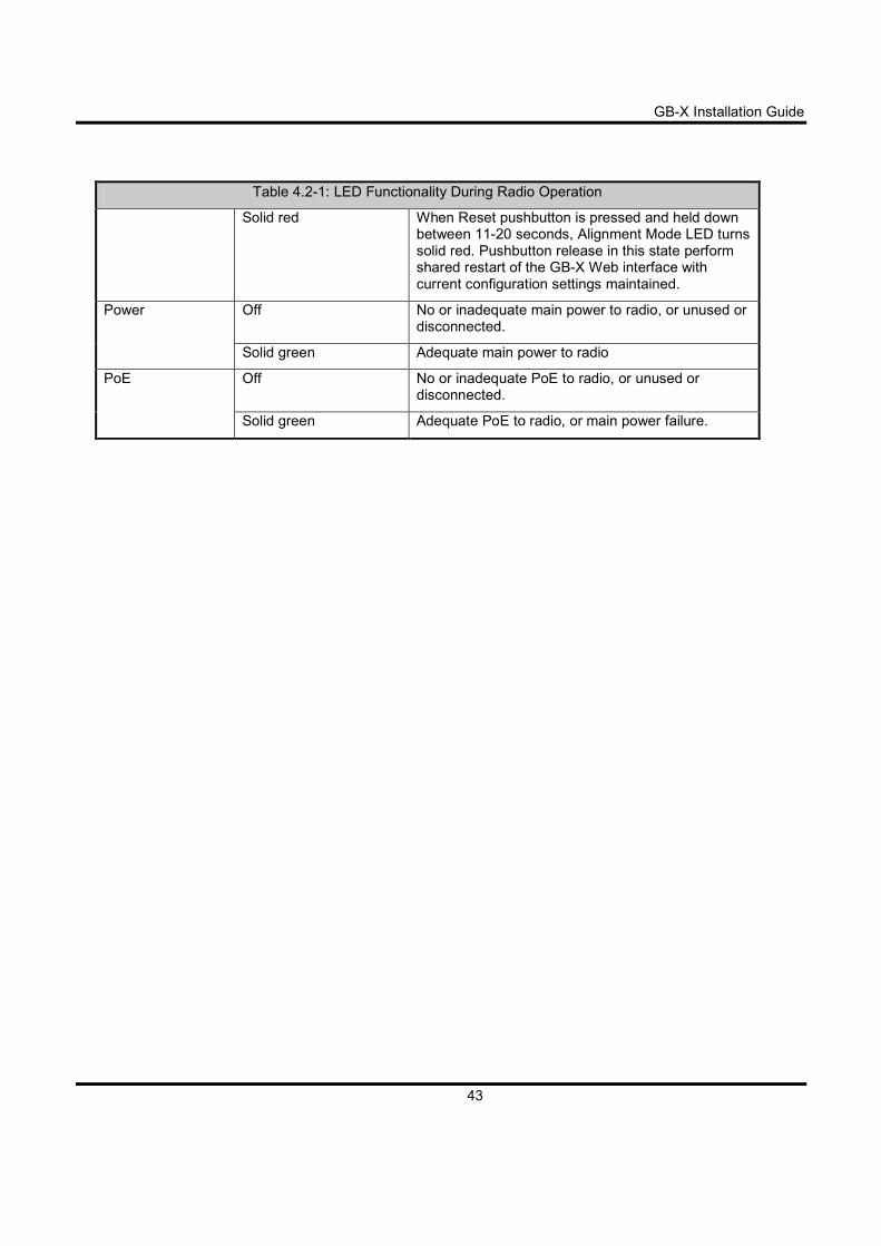
Table 4.2-1: LED Functionality During Radio Operation
Solid red When Reset pushbutton is pressed and held down between 11-20 seconds, Alignment Mode LED turns solid red. Pushbutton release in this state perform shared restart of the GB-X Web interface with current configuration settings maintained.
Power Off No or inadequate main power to radio, or unused or disconnected.
Solid green Adequate main power to radio
PoE Off No or inadequate PoE to radio, or unused or disconnected.
Solid green Adequate PoE to radio, or main power failure.
GB-X Installation Guide
44
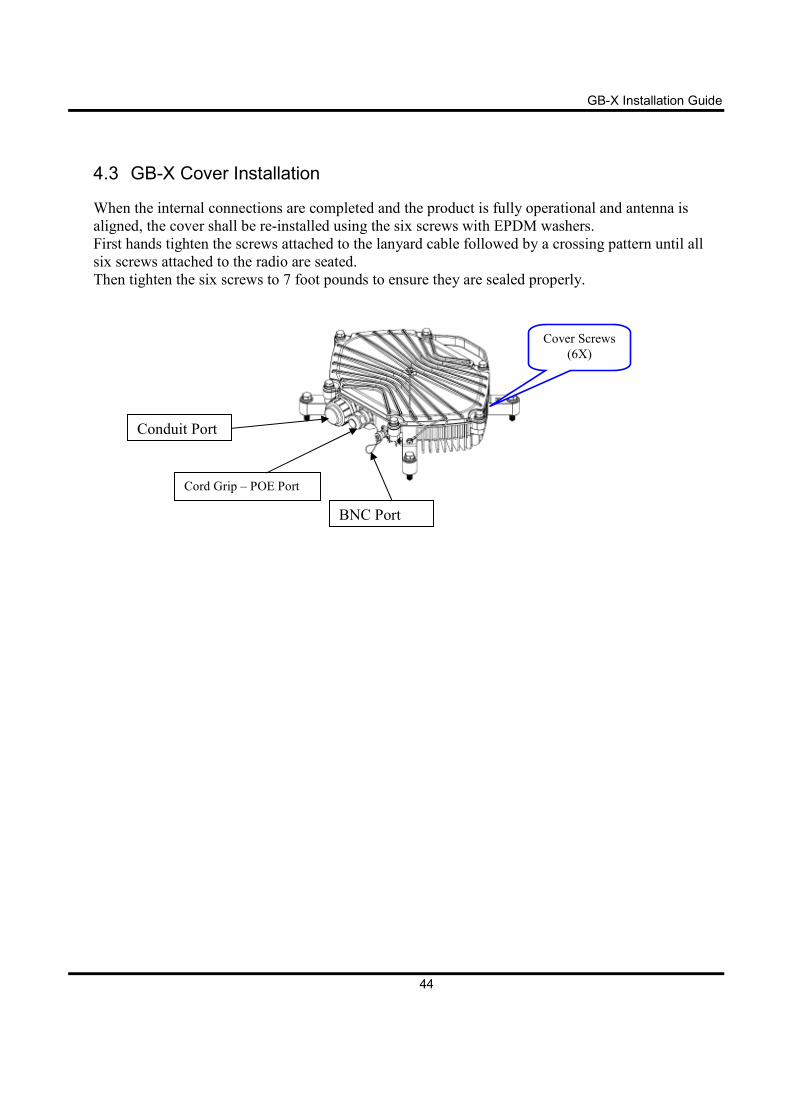
4.3 GB-X Cover Installation
When the internal connections are completed and the product is fully operational and antenna is
aligned, the cover shall be re-installed using the six screws with EPDM washers.
First hands tighten the screws attached to the lanyard cable followed by a crossing pattern until all
six screws attached to the radio are seated.
Then tighten the six screws to 7 foot pounds to ensure they are sealed properly.
Conduit Port
Cord Grip – POE Port
BNC Port
Cover Screws
(6X)
GB-X Installation Guide
45
4.4 Connecting Network Equipment
The networking equipment that will be connected to the GB-X system should be pre-checked to
ensure it operates properly back-to-back over a wired connection. Once this has been confirmed, it
will save troubleshooting steps if a traffic problem arises after the radio is installed and connected to
the network equipment.
The 1000Base-X interfaces are factory pre-configured for Auto-Negotiation (AN) and flow control
enabled. Auto-negotiation and flow control can be disabled via the GB-X Web interface. The
networking equipment interfaces must be set to match the Radio’s interface settings to allow for
proper traffic flow.
The GB-X radios support all standard Ethernet frame sizes up to
10,240 bytes for un-tagged or 802.1q VLAN-tagged frames.
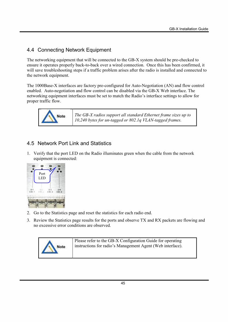
4.5 Network Port Link and Statistics
1. Verify that the port LED on the Radio illuminates green when the cable from the network
equipment is connected:
2. Go to the Statistics page and reset the statistics for each radio end.
3. Review the Statistics page results for the ports and observe TX and RX packets are flowing and
no excessive error conditions are observed.
Please refer to the GB-X Configuration Guide for operating
instructions for radio’s Management Agent (Web interface).
Port
LED
GB-X Installation Guide
46
5 1+1 Protection and 2+0 OMT-80 Installation
This section describes installing a system with one of the following redundancy options, which
consists of two radios mounted on an outdoor unit (ODU) coupler, with one antenna, on each side of
the link:
• Unequal-Loss Couplers for 1+1 Hot Standby Protection (Protection) – This coupler is
recommended for Protection links.
• 2+0 Orthogonal Mode Transducer (OMT-80) – The OMT-80 provides a mechanism
whereby each radio transmits and receives over independent polarities. One radio uses
vertical polarity, while the other radio uses horizontal polarity. The OMT-80 is recommended
for 2+0 links.
5.1 1+1 Protection Overview
1+1 Protection provides system redundancy that will take effect when a failure is detected. This
ensures system-level mitigation of local hardware problems.
Matching Ethernet ports on the active and standby radios are connected with fiber splitters. In this
way, both radios receive the same data from the customer.
Radios equipped with copper SFPs cannot be protected and must
be reconfigured with optical SFPs to implement Protection
configurations.
The Protection port connects both radios with an outdoor-ratedCat6A cable. The radios
communicate their Protection status messages over this connection.
GB-X Installation Guide
47
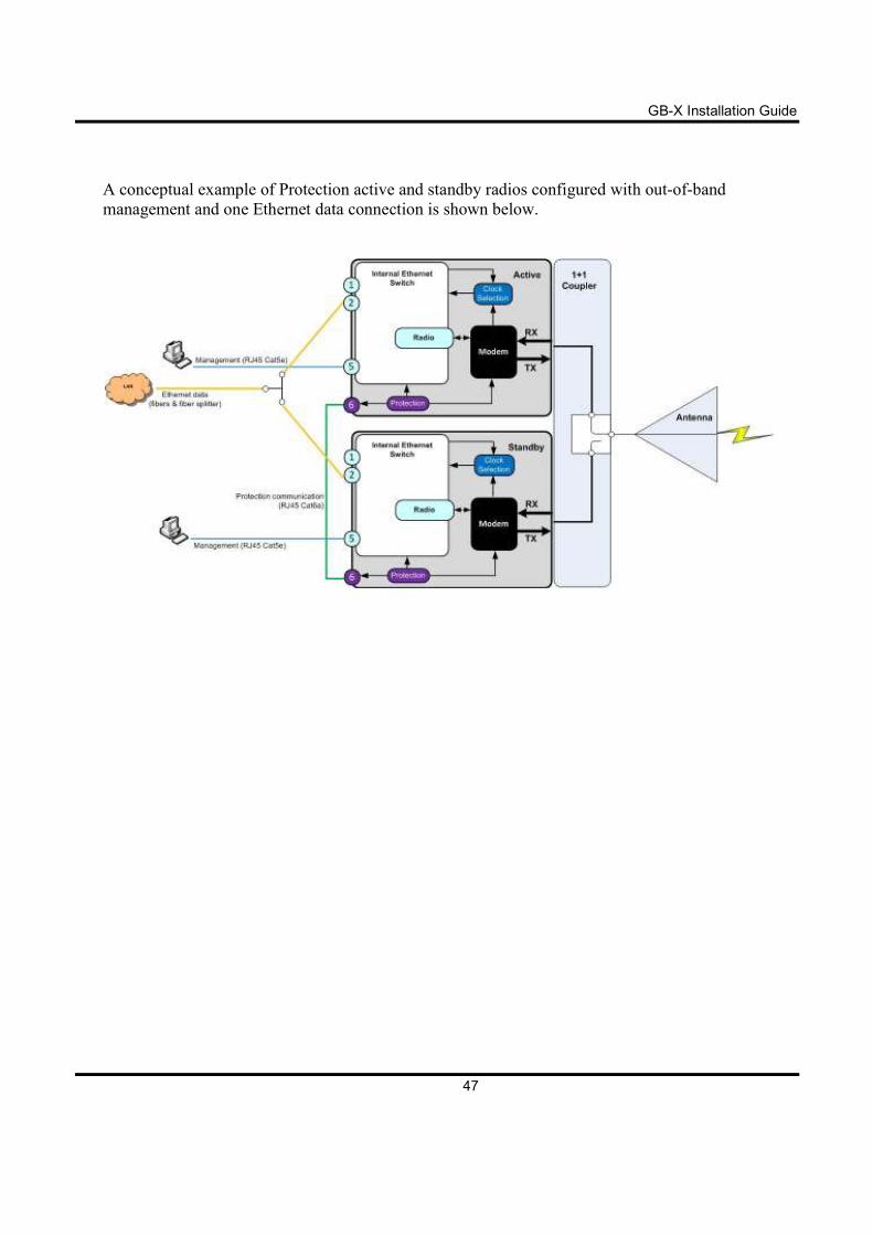
A conceptual example of Protection active and standby radios configured with out-of-band
management and one Ethernet data connection is shown below.
GB-X Installation Guide
48
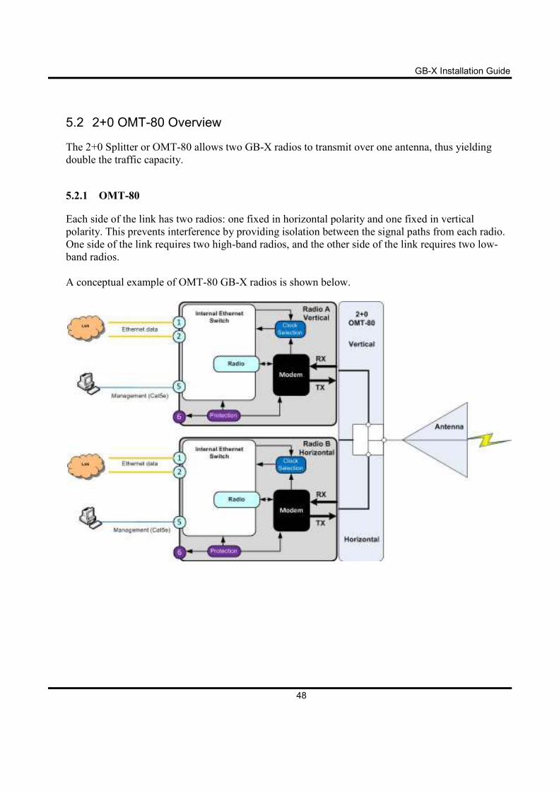
5.2 2+0 OMT-80 Overview
The 2+0 Splitter or OMT-80 allows two GB-X radios to transmit over one antenna, thus yielding
double the traffic capacity.
5.2.1 OMT-80
Each side of the link has two radios: one fixed in horizontal polarity and one fixed in vertical
polarity. This prevents interference by providing isolation between the signal paths from each radio.
One side of the link requires two high-band radios, and the other side of the link requires two low-
band radios.
A conceptual example of OMT-80 GB-X radios is shown below.
GB-X Installation Guide
49
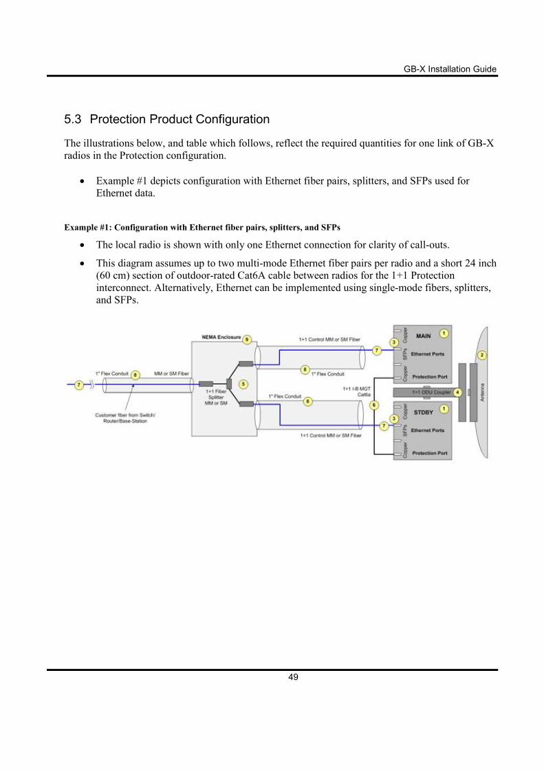
5.3 Protection Product Configuration
The illustrations below, and table which follows, reflect the required quantities for one link of GB-X
radios in the Protection configuration.
• Example #1 depicts configuration with Ethernet fiber pairs, splitters, and SFPs used for
Ethernet data.
Example #1: Configuration with Ethernet fiber pairs, splitters, and SFPs
• The local radio is shown with only one Ethernet connection for clarity of call-outs.
• This diagram assumes up to two multi-mode Ethernet fiber pairs per radio and a short 24 inch
(60 cm) section of outdoor-rated Cat6A cable between radios for the 1+1 Protection
interconnect. Alternatively, Ethernet can be implemented using single-mode fibers, splitters,
and SFPs.
GB-X Installation Guide
50
5.4 Cabling Considerations
5.4.1 Protection
Protection is only applicable for fiber-optic, not copper, SFP
modules.
The following describes cabling between the active and standby radios.
Example #1: Configuration with Ethernet fiber pairs, splitters, and SFPs
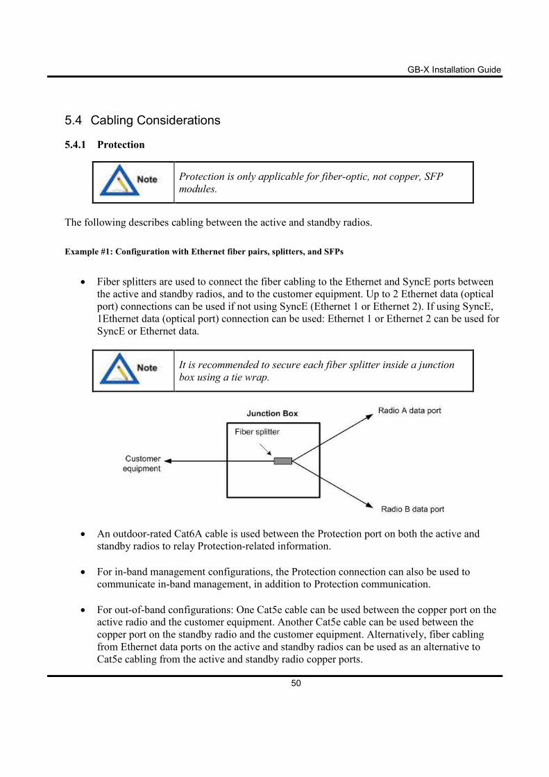
• Fiber splitters are used to connect the fiber cabling to the Ethernet and SyncE ports between
the active and standby radios, and to the customer equipment. Up to 2 Ethernet data (optical
port) connections can be used if not using SyncE (Ethernet 1 or Ethernet 2). If using SyncE,
1Ethernet data (optical port) connection can be used: Ethernet 1 or Ethernet 2 can be used for
SyncE or Ethernet data.
It is recommended to secure each fiber splitter inside a junction
box using a tie wrap.
• An outdoor-rated Cat6A cable is used between the Protection port on both the active and
standby radios to relay Protection-related information.
• For in-band management configurations, the Protection connection can also be used to
communicate in-band management, in addition to Protection communication.
• For out-of-band configurations: One Cat5e cable can be used between the copper port on the active radio and the customer equipment. Another Cat5e cable can be used between the
copper port on the standby radio and the customer equipment. Alternatively, fiber cabling
from Ethernet data ports on the active and standby radios can be used as an alternative to
Cat5e cabling from the active and standby radio copper ports.
GB-X Installation Guide
51
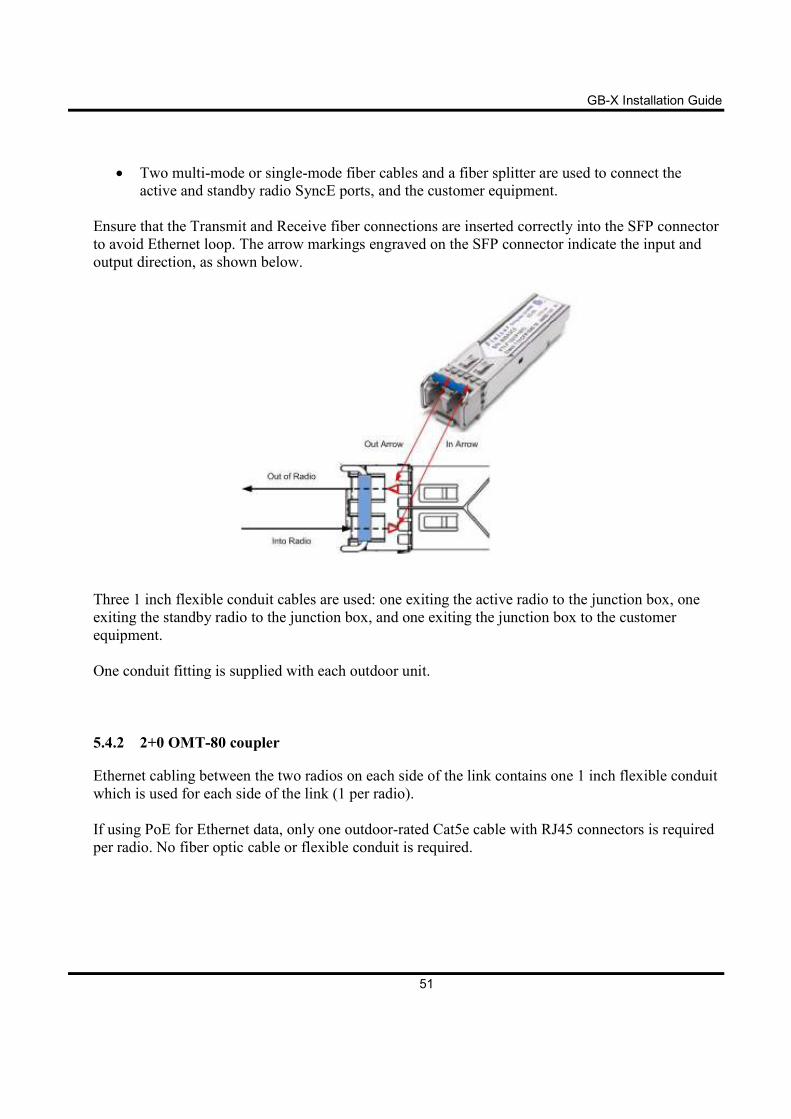
• Two multi-mode or single-mode fiber cables and a fiber splitter are used to connect the
active and standby radio SyncE ports, and the customer equipment.
Ensure that the Transmit and Receive fiber connections are inserted correctly into the SFP connector
to avoid Ethernet loop. The arrow markings engraved on the SFP connector indicate the input and
output direction, as shown below.
Three 1 inch flexible conduit cables are used: one exiting the active radio to the junction box, one
exiting the standby radio to the junction box, and one exiting the junction box to the customer
equipment.
One conduit fitting is supplied with each outdoor unit.
5.4.2 2+0 OMT-80 coupler
Ethernet cabling between the two radios on each side of the link contains one 1 inch flexible conduit
which is used for each side of the link (1 per radio).
If using PoE for Ethernet data, only one outdoor-rated Cat5e cable with RJ45 connectors is required
per radio. No fiber optic cable or flexible conduit is required.
GB-X Installation Guide
52
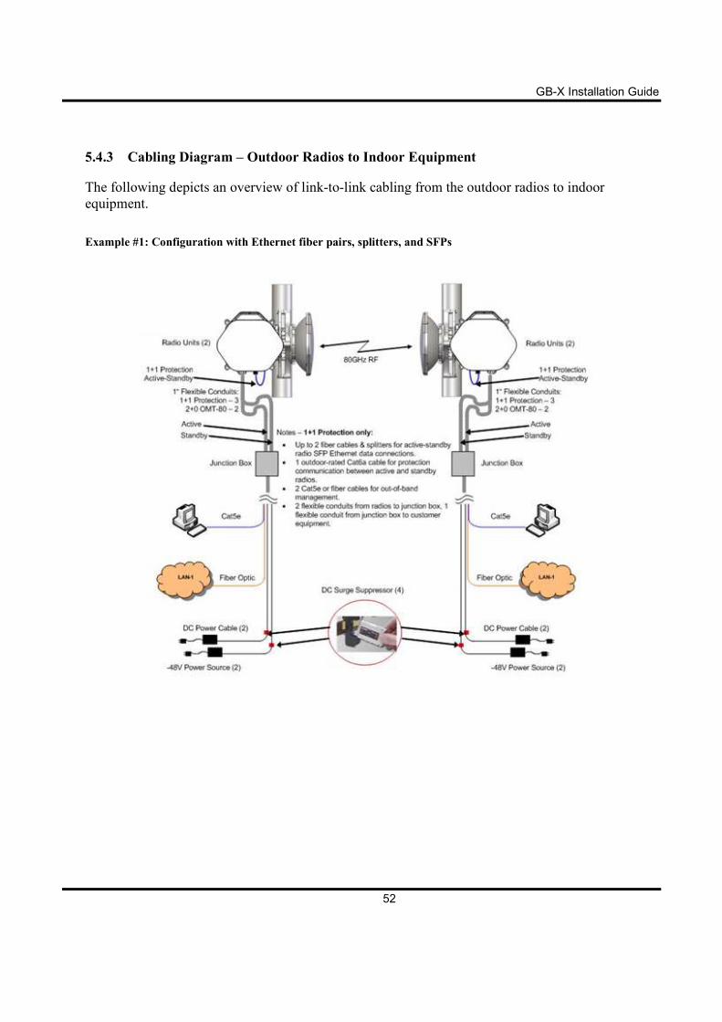
5.4.3 Cabling Diagram – Outdoor Radios to Indoor Equipment
The following depicts an overview of link-to-link cabling from the outdoor radios to indoor
equipment.
Example #1: Configuration with Ethernet fiber pairs, splitters, and SFPs
GB-X Installation Guide
53
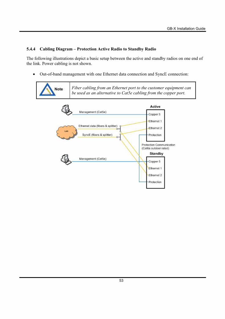
5.4.4 Cabling Diagram – Protection Active Radio to Standby Radio
The following illustrations depict a basic setup between the active and standby radios on one end of
the link. Power cabling is not shown.
• Out-of-band management with one Ethernet data connection and SyncE connection:
Fiber cabling from an Ethernet port to the customer equipment can
be used as an alternative to Cat5e cabling from the copper port.
GB-X Installation Guide
54
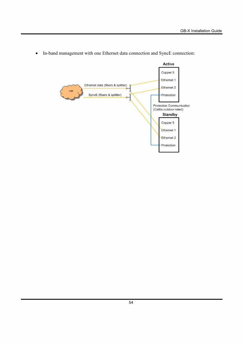
• In-band management with one Ethernet data connection and SyncE connection:
GB-X Installation Guide
55
5.5 Changing Polarity on 1+1 Protection Couplers
This subsection applies only to Protection couplers and not the
OMT-80, because the OMT-80 has fixed polarity.
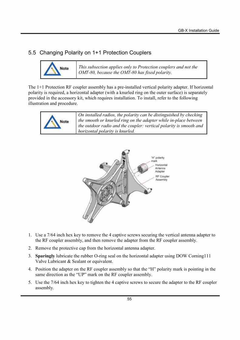
The 1+1 Protection RF coupler assembly has a pre-installed vertical polarity adapter. If horizontal
polarity is required, a horizontal adapter (with a knurled ring on the outer surface) is separately
provided in the accessory kit, which requires installation. To install, refer to the following
illustration and procedure.
On installed radios, the polarity can be distinguished by checking
the smooth or knurled ring on the adapter while in-place between
the outdoor radio and the coupler: vertical polarity is smooth and
horizontal polarity is knurled.
1. Use a 7/64 inch hex key to remove the 4 captive screws securing the vertical antenna adapter to
the RF coupler assembly, and then remove the adapter from the RF coupler assembly.
2. Remove the protective cap from the horizontal antenna adapter.
3. Sparingly lubricate the rubber O-ring seal on the horizontal adapter using DOW Corning111
Valve Lubricant & Sealant or equivalent.
4. Position the adapter on the RF coupler assembly so that the “H” polarity mark is pointing in the
same direction as the “UP” mark on the RF coupler assembly.
5. Use the 7/64 inch hex key to tighten the 4 captive screws to secure the adapter to the RF coupler
assembly.
GB-X Installation Guide
56
5.6 Antenna Mount Installation
For antenna mount installation instructions, please refer to your antenna manufacturer’s installation
guide to perform the following:
1. Assemble the antenna mounting hardware.
2. Mount the antenna to the mast.
3. Remove the protective plastic cap from the antenna port.
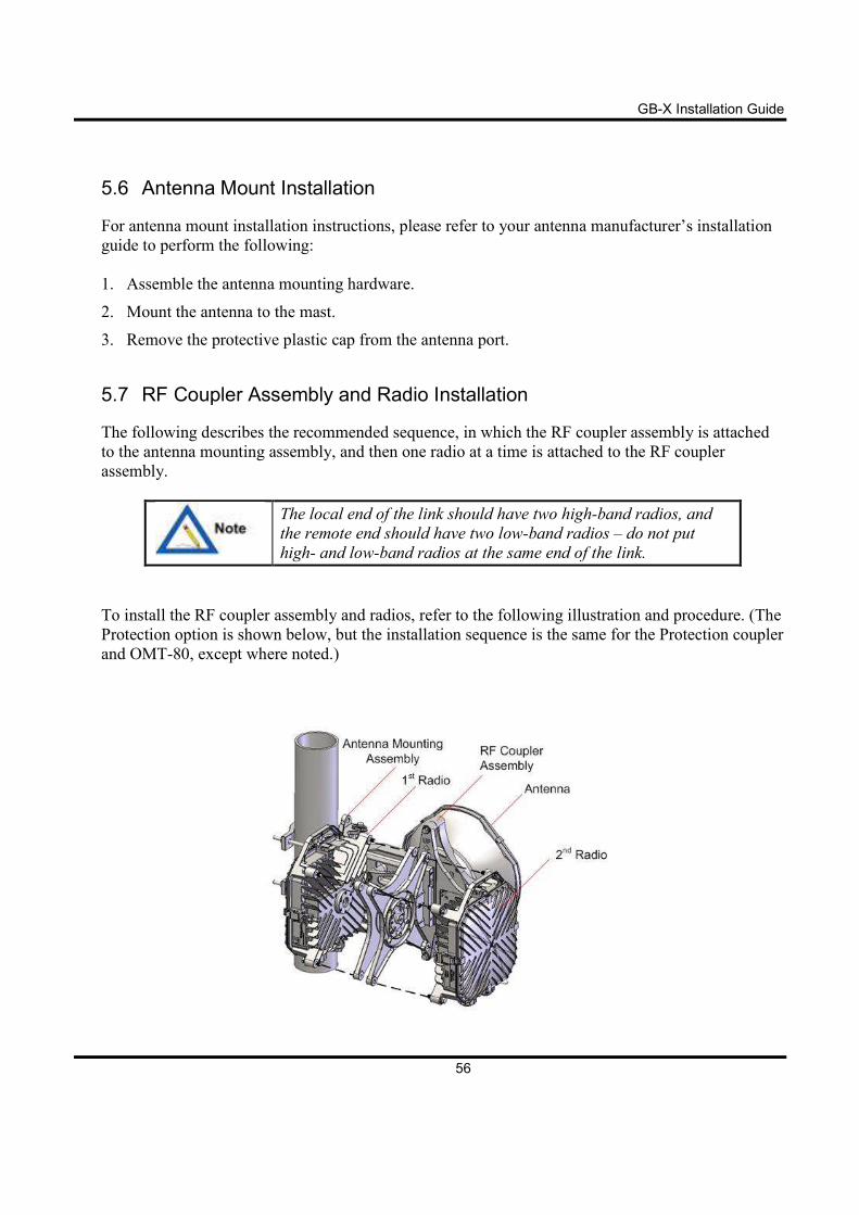
5.7 RF Coupler Assembly and Radio Installation
The following describes the recommended sequence, in which the RF coupler assembly is attached
to the antenna mounting assembly, and then one radio at a time is attached to the RF coupler
assembly.
The local end of the link should have two high-band radios, and
the remote end should have two low-band radios – do not put
high- and low-band radios at the same end of the link.
To install the RF coupler assembly and radios, refer to the following illustration and procedure. (The
Protection option is shown below, but the installation sequence is the same for the Protection coupler
and OMT-80, except where noted.)
GB-X Installation Guide
57
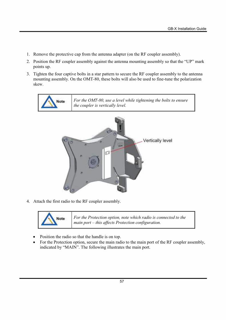
1. Remove the protective cap from the antenna adapter (on the RF coupler assembly).
2. Position the RF coupler assembly against the antenna mounting assembly so that the “UP” mark
points up.
3. Tighten the four captive bolts in a star pattern to secure the RF coupler assembly to the antenna
mounting assembly. On the OMT-80, these bolts will also be used to fine-tune the polarization
skew.
For the OMT-80, use a level while tightening the bolts to ensure
the coupler is vertically level.
4. Attach the first radio to the RF coupler assembly.
For the Protection option, note which radio is connected to the
main port – this affects Protection configuration.
• Position the radio so that the handle is on top.
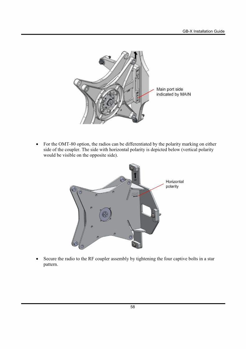
• For the Protection option, secure the main radio to the main port of the RF coupler assembly,
indicated by “MAIN”. The following illustrates the main port.
GB-X Installation Guide
58
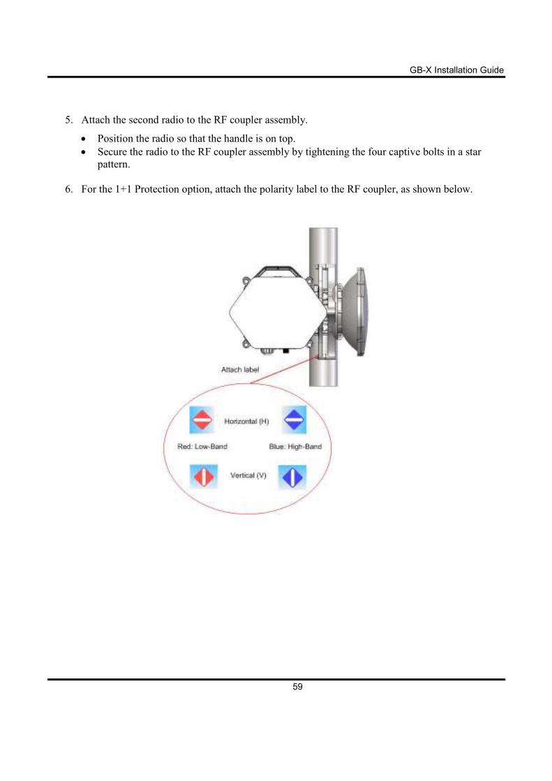
• For the OMT-80 option, the radios can be differentiated by the polarity marking on either
side of the coupler. The side with horizontal polarity is depicted below (vertical polarity
would be visible on the opposite side).
• Secure the radio to the RF coupler assembly by tightening the four captive bolts in a star
pattern.
GB-X Installation Guide
59
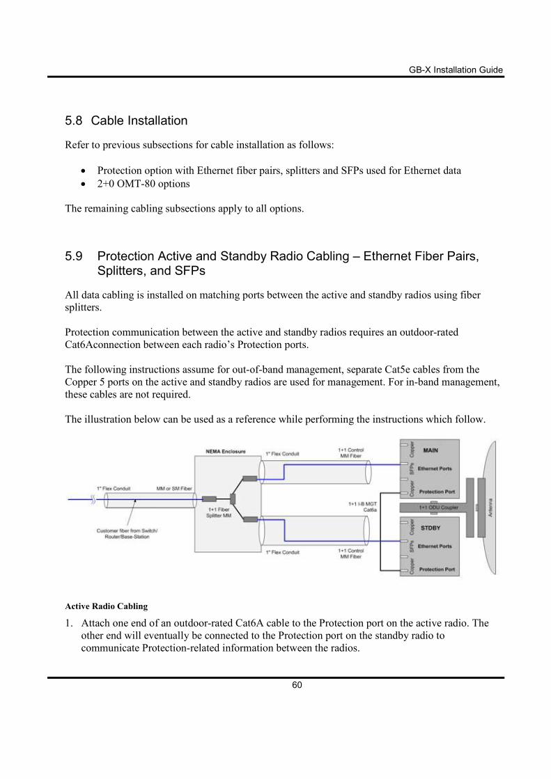
5. Attach the second radio to the RF coupler assembly.
• Position the radio so that the handle is on top.
• Secure the radio to the RF coupler assembly by tightening the four captive bolts in a star
pattern.
6. For the 1+1 Protection option, attach the polarity label to the RF coupler, as shown below.
GB-X Installation Guide
60
5.8 Cable Installation
Refer to previous subsections for cable installation as follows:
• Protection option with Ethernet fiber pairs, splitters and SFPs used for Ethernet data
• 2+0 OMT-80 options
The remaining cabling subsections apply to all options.
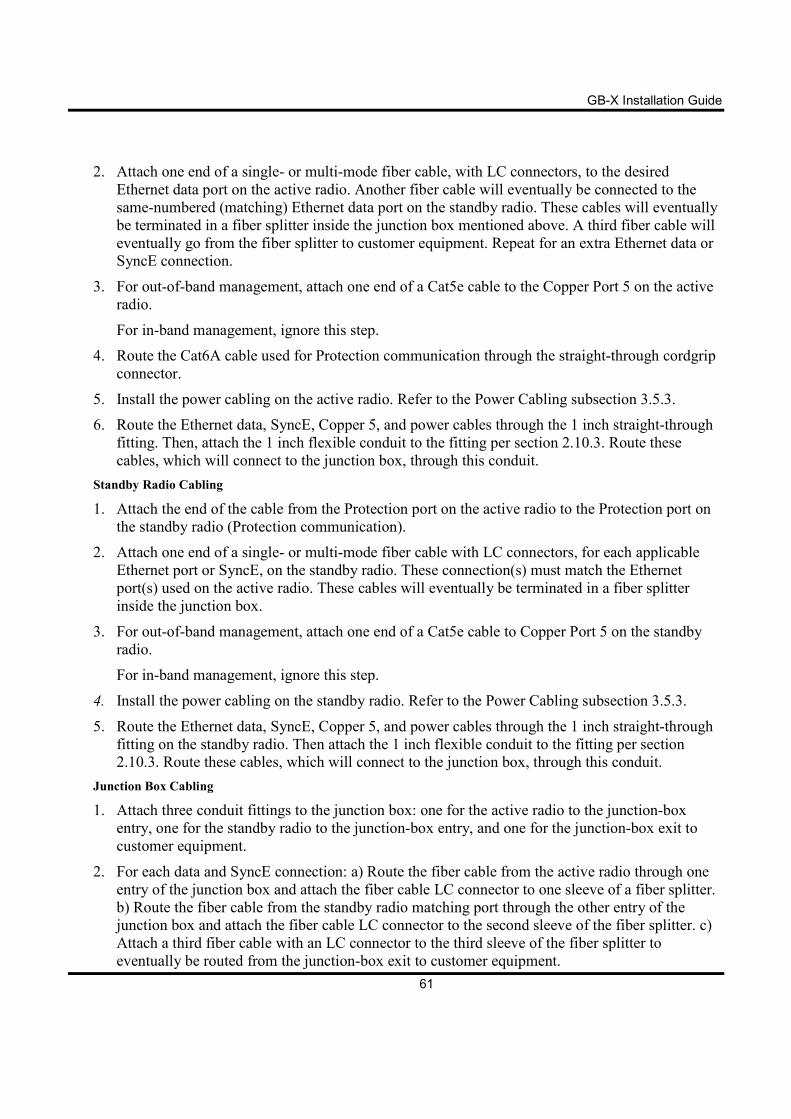
5.9 Protection Active and Standby Radio Cabling – Ethernet Fiber Pairs, Splitters, and SFPs
All data cabling is installed on matching ports between the active and standby radios using fiber
splitters.
Protection communication between the active and standby radios requires an outdoor-rated
Cat6Aconnection between each radio’s Protection ports.
The following instructions assume for out-of-band management, separate Cat5e cables from the
Copper 5 ports on the active and standby radios are used for management. For in-band management,
these cables are not required.
The illustration below can be used as a reference while performing the instructions which follow.
Active Radio Cabling
1. Attach one end of an outdoor-rated Cat6A cable to the Protection port on the active radio. The
other end will eventually be connected to the Protection port on the standby radio to
communicate Protection-related information between the radios.
GB-X Installation Guide
61
2. Attach one end of a single- or multi-mode fiber cable, with LC connectors, to the desired
Ethernet data port on the active radio. Another fiber cable will eventually be connected to the
same-numbered (matching) Ethernet data port on the standby radio. These cables will eventually
be terminated in a fiber splitter inside the junction box mentioned above. A third fiber cable will
eventually go from the fiber splitter to customer equipment. Repeat for an extra Ethernet data or
SyncE connection.
3. For out-of-band management, attach one end of a Cat5e cable to the Copper Port 5 on the active
radio.
For in-band management, ignore this step.
4. Route the Cat6A cable used for Protection communication through the straight-through cordgrip
connector.
5. Install the power cabling on the active radio. Refer to the Power Cabling subsection 3.5.3.
6. Route the Ethernet data, SyncE, Copper 5, and power cables through the 1 inch straight-through
fitting. Then, attach the 1 inch flexible conduit to the fitting per section 2.10.3. Route these
cables, which will connect to the junction box, through this conduit.
Standby Radio Cabling
1. Attach the end of the cable from the Protection port on the active radio to the Protection port on
the standby radio (Protection communication).
2. Attach one end of a single- or multi-mode fiber cable with LC connectors, for each applicable
Ethernet port or SyncE, on the standby radio. These connection(s) must match the Ethernet
port(s) used on the active radio. These cables will eventually be terminated in a fiber splitter
inside the junction box.
3. For out-of-band management, attach one end of a Cat5e cable to Copper Port 5 on the standby
radio.
For in-band management, ignore this step.
4. Install the power cabling on the standby radio. Refer to the Power Cabling subsection 3.5.3.
5. Route the Ethernet data, SyncE, Copper 5, and power cables through the 1 inch straight-through
fitting on the standby radio. Then attach the 1 inch flexible conduit to the fitting per section
2.10.3. Route these cables, which will connect to the junction box, through this conduit.
Junction Box Cabling
1. Attach three conduit fittings to the junction box: one for the active radio to the junction-box
entry, one for the standby radio to the junction-box entry, and one for the junction-box exit to
customer equipment.
2. For each data and SyncE connection: a) Route the fiber cable from the active radio through one
entry of the junction box and attach the fiber cable LC connector to one sleeve of a fiber splitter.
b) Route the fiber cable from the standby radio matching port through the other entry of the
junction box and attach the fiber cable LC connector to the second sleeve of the fiber splitter. c)
Attach a third fiber cable with an LC connector to the third sleeve of the fiber splitter to
eventually be routed from the junction-box exit to customer equipment.
GB-X Installation Guide
62
It is recommended to secure the fiber splitters inside the junction
box using a tie wrap.
3. For out-of-band management, a) Route the cable from the active radio Copper 5 port through the
junction-box entry designated for the active radio. b) Route the cable from the standby radio
Copper 5 port through the junction-box entry designated for the standby radio.
4. Route the power cable from the active radio through the junction-box entry designated for the
active radio; route the power cable from the active radio through the junction-box entry
designated for the standby radio.
5. Attach 1 inch flexible conduit to both junction box entries.
6. Route the following cables through the junction-box exit: data and SyncE fiber cables from the
third sleeve of the fiber splitters, Copper 5 port, and power.
7. Attach 1 inch flexible conduit to the junction-box exit.
8. Connect the fiber and Cat5e cables at the customer equipment.
5.10 2+0 OMT-80 Fiber, Power & Ground Cabling
1. Install the desired SFP modules in the radio with duplex MMF or SMF fiber from the radio to the
network termination equipment (switch or router with 1000Base-X port). The cable should be
looped around the inside of the enclosure to provide strain-relief per Figure 3.7.3 1. The
connectors on the radio end of the fiber require a duplex LC connector; the connectors on the
switch/router end should mate to the network equipment.
2. Connect the fibers at the network equipment.
If using PoE for Ethernet data, connect outdoor-rated Cat5e RJ45
cables from the Copper #5 port of each radio to the PoE enabled
devices. No SFPs or fibers are required.
3. Please refer to the Power Cabling subsection 3.5.3.
4. Please refer to the Ground Cabling subsection 3.5.2
GB-X Installation Guide
63
5.11 2+0 OMT Antenna Polarization Adjustment
Align the antenna as detailed in the Antenna Alignment subsection 3.6.
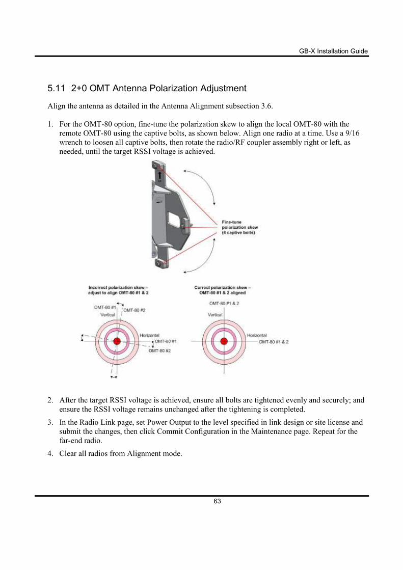
1. For the OMT-80 option, fine-tune the polarization skew to align the local OMT-80 with the
remote OMT-80 using the captive bolts, as shown below. Align one radio at a time. Use a 9/16
wrench to loosen all captive bolts, then rotate the radio/RF coupler assembly right or left, as
needed, until the target RSSI voltage is achieved.
2. After the target RSSI voltage is achieved, ensure all bolts are tightened evenly and securely; and
ensure the RSSI voltage remains unchanged after the tightening is completed.
3. In the Radio Link page, set Power Output to the level specified in link design or site license and
submit the changes, then click Commit Configuration in the Maintenance page. Repeat for the
far-end radio.
4. Clear all radios from Alignment mode.
GB-X Installation Guide
64
Appendix A Troubleshooting
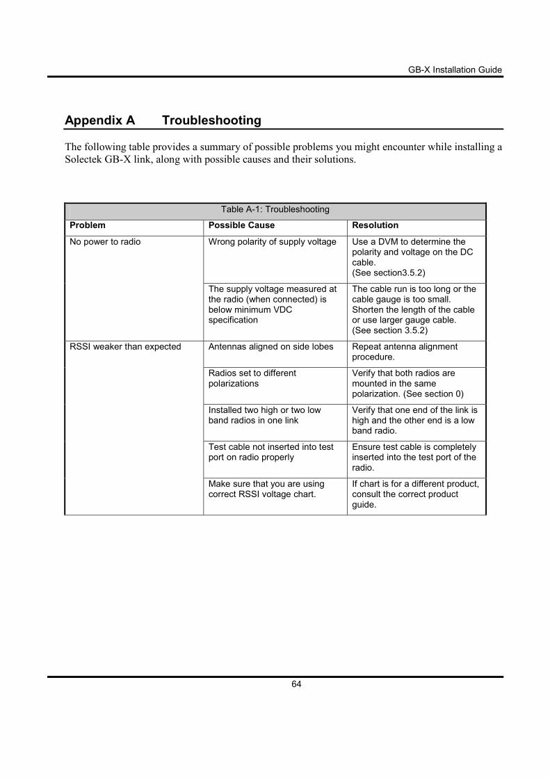
The following table provides a summary of possible problems you might encounter while installing a
Solectek GB-X link, along with possible causes and their solutions.
Table A-1: Troubleshooting
Problem Possible Cause Resolution
No power to radio Wrong polarity of supply voltage Use a DVM to determine the polarity and voltage on the DC cable. (See section3.5.2)
The supply voltage measured at the radio (when connected) is below minimum VDC specification
The cable run is too long or the cable gauge is too small. Shorten the length of the cable or use larger gauge cable. (See section 3.5.2)
RSSI weaker than expected Antennas aligned on side lobes Repeat antenna alignment procedure.
Radios set to different polarizations
Verify that both radios are mounted in the same polarization. (See section 0)
Installed two high or two low band radios in one link
Verify that one end of the link is high and the other end is a low band radio.
Test cable not inserted into test port on radio properly
Ensure test cable is completely inserted into the test port of the radio.
Make sure that you are using correct RSSI voltage chart.
If chart is for a different product, consult the correct product guide.
GB-X Installation Guide
65
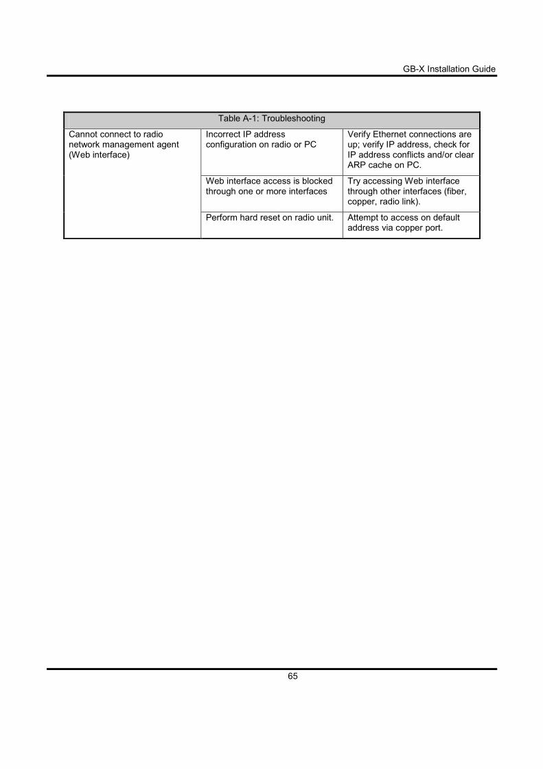
Table A-1: Troubleshooting
Cannot connect to radio network management agent (Web interface)
Incorrect IP address configuration on radio or PC
Verify Ethernet connections are up; verify IP address, check for IP address conflicts and/or clear ARP cache on PC.
Web interface access is blocked through one or more interfaces
Try accessing Web interface through other interfaces (fiber, copper, radio link).
Perform hard reset on radio unit. Attempt to access on default address via copper port.
GB-X Installation Guide
66
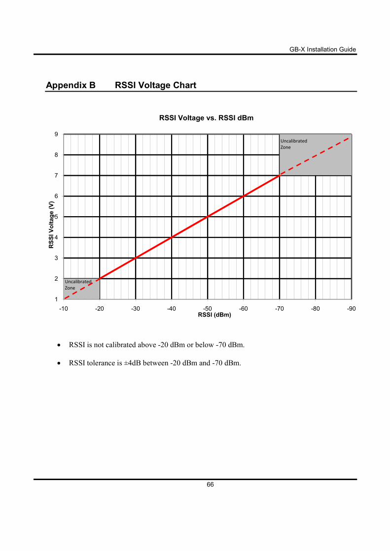
Appendix B RSSI Voltage Chart
• RSSI is not calibrated above -20 dBm or below -70 dBm.
• RSSI tolerance is ±4dB between -20 dBm and -70 dBm.
1
2
3
4
5
6
7
8
9
-90-80-70-60-50-40-30-20-10
RSSI Voltage (V)
RSSI (dBm)
RSSI Voltage vs. RSSI dBm
Uncalibrated
Zone
Uncalibrated
Zone
GB-X Installation Guide
67
Appendix C Reset Button
Performing Hard Reset
Hold the reset button down until the Alignment mode LED turns red to verify the reset is started,
then immediately release the button
Once the hard reset operation is started, a link outage will occur
until the reset is complete.
The GB-X Web interface will also not be available until the reset
is complete.
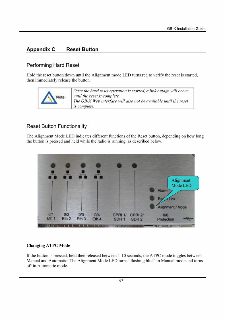
Reset Button Functionality
The Alignment Mode LED indicates different functions of the Reset button, depending on how long
the button is pressed and held while the radio is running, as described below.
Changing ATPC Mode
If the button is pressed, held then released between 1-10 seconds, the ATPC mode toggles between
Manual and Automatic. The Alignment Mode LED turns “flashing blue” in Manual mode and turns
off in Automatic mode.
Alignment
Mode LED
GB-X Installation Guide
68
Hard Restart
If the button is pressed and held between 11-20 seconds or when the LED starts flashing RED then
released, the radio performs a hard restart equivalent to the Web interface (the radio is restarted, and
current configuration settings are maintained).
Factory Hard Reset
If the button is pressed and held between 21-30 seconds or until the LED turns RED, then released,
the radio is defaulted to factory configuration settings and restarted.
If the button is pressed and held between 30-60 seconds, no action
occurs.