Embed Size (px)
Citation preview

arX
iv:1
606.
0816
3v1
[co
nd-m
at.m
es-h
all]
27
Jun
2016
Skyrmions at the edge: Confinement effects in Fe/Ir(111)
Julian Hagemeister, Davide Iaia,∗ Elena Y. Vedmedenko,
Kirsten von Bergmann, Andre Kubetzka,† and Roland WiesendangerDepartment of Physics, University of Hamburg, D-20355 Hamburg, Germany
(Dated: July 31, 2018)
We have employed spin-polarized scanning tunneling microscopy and Monte-Carlo simulations toinvestigate the effect of lateral confinement onto the nanoskyrmion lattice in Fe/Ir(111). We finda strong coupling of one diagonal of the square magnetic unit cell to the close-packed edges of Fenanostructures. In triangular islands this coupling in combination with the mismatching symmetriesof the islands and of the square nanoskyrmion lattice leads to frustration and triple-domain states.In direct vicinity to ferromagnetic NiFe islands, the surrounding skyrmion lattice forms additionaldomains. In this case a side of the square magnetic unit cell prefers a parallel orientation to theferromagnetic edge. These experimental findings can be reproduced and explained by Monte-Carlosimulations. Here, the single-domain state of a triangular island is lower in energy, but neverthelessmulti-domain states occur due to the combined effect of entropy and an intrinsic domain wall pinningarising from the skyrmionic character of the spin texture.
Magnetic skyrmions are particle-like states [1] whichcan occur in magnetic systems with broken inversionsymmetry due to the Dzyaloshinskii-Moriya interac-tion [2, 3]. Skyrmions can either form lattices at certainfield ranges [4–10] or they can be created and manip-ulated individually [9], thereby offering great potentialfor data storage, transfer and processing [11, 12]. Sincethe geometric layout is an essential part of a device, the-oretical investigations explored the effect of boundariesand confinement in skyrmionic systems [13, 14]. For in-stance, skyrmion movement in racetracks [12] and theeffect of notches [15] on their trajectories were studiedand lateral confinement was suggested as a means to sta-bilize skyrmions without an external magnetic field [16].However, the relative orientation of skyrmion lattices inregard to the geometry of the boundary of magnetic sys-tems is still an open question. Most experiments focusedon extended films and on their temperature and field-dependence while finite size effects were explored onlyvery recently, e.g. in nanostripes [17] or in disk-shapedstructures [18, 19].
Here, we employ spin-polarized scanning tunneling mi-croscopy (SP-STM) and Monte-Carlo (MC) simulationsto investigate the effect of two types of boundaries ontothe nanoskyrmion lattice in the Fe atomic monolayer onIr(111). This skyrmion lattice has four-fold symmetry, aperiod of about 1 nm, and exists already in zero field dueto the four-spin interaction [6]. At T = 4.2K it is insensi-tive to fields of up to 9 Tesla [20], which shows that it hasa vanishing net moment. In extended films, three rota-tional domains can be found [6], where a diagonal of themagnetic unit cell aligns with one of the three symmetryequivalent close-packed atomic rows of the hexagonal Felayer. Our new data show that at a close-packed edgeof an Fe nanostructure, one diagonal of the magneticunit cell is preferentially oriented parallel to the edge,i.e. the edge selects one of the three rotational domains.In triangular islands, this coupling leads to frustration
and triple-domain states with domain wall widths on theorder of the skyrmion size. For the more common hexa-gonal skyrmion lattices, such a frustration effect mightoccur, e.g., in rectangular-shaped structures. The MCsimulations with open boundary conditions already ex-hibit the same kind of coupling, but with unaltered in-teractions at the edge, multi-domains are metastable intriangular structures, i.e. a single-domain state has thelowest energy. This metastability arises from the spa-tially inhomogeneous, periodic energy distribution of thenanoskyrmion lattice, which creates additional energybarriers. The second edge we investigate is ferromag-netic with out-of-plane easy axis. Here, we find a pre-ferred orientation of the skyrmion lattice with one sideof the magnetic unit cell parallel to the edge, both inthe experiment and the MC simulation. This rotationaldomain is neither found in extended films nor in islands,showing that controlling boundary conditions is a way totailor specific properties in skyrmionic systems.
The Fe was evaporated onto the clean Ir(111) surfaceat room temperature to ensure island growth, see sup-plemental material for details. Fig. 1 shows a currentmap of a sample area exhibiting both an extended fcc Featomic monolayer high wire, which has grown from anIr step edge (upper left of Fig. 1), and two free-standingfcc Fe islands. A current map measured with the feed-back loop active, as in Fig. 1, is essentially equivalent toa differentiated topography image, dz/dx(x, y), and al-lows to show small-scale structures on large areas and ondifferent height levels without the need for image pro-cessing. Three types of rotational domains can be seenand have been labeled A, B and C. The domain lengthswithin wires can easily reach 100nm, see supplementalFig. S1. Commonly observed one-dimensional defects ofthe magnetic texture within the wires are dislocationlines, see left inset, separating equivalent but laterallyshifted skyrmion lattices. Apparently they result fromstress, which might arise from a varying wire width or

2
A
B
CB
C
BC
10 nm3 nm
B
AA
2nd layer Fe/Ir
Fe/Ir
Ir(111)
FIG. 1: (color online) Coupling of nanoskyrmion lattice to close-packed edges. Spin-polarized STM current map of fcc Fe onIr(111), the insets show topographic data in gray. Measurement parameters: I = 1nA, U = 20mV, T = 7.7K, B = 1.5T, bulkCr tip. We observe three rotational domains of the nanoskyrmion lattice, labeled A, B and C, which show a strong correlationto the Fe step edge direction, i.e. one diagonal of the magnetic unit cell shows a preferrence for coupling parallel to the edge.The mismatching symmetry of the square nanoskyrmion lattice and the triangular shape of islands leads to frustration and theformation of domain walls.
from pinning at remaining defects within the layer. Therotational domains exhibit a clear trend of coupling witha diagonal of the magnetic unit cell parallel to straight,close-packed edges: in the wire in Fig. 1, two C domainsand an A domain are found at respective edges, whilethe surrounding domain is of type B. In the case of the Cdomains a defect and the 2nd layer Fe island might haveplayed a role in the domain formation, but no defectsare found in the vicinity of the A domain. This kind ofedge domain is much rarer in wires with smoother edges,see supplemental Fig. S1. In the islands, due to their de-fined shapes, the coupling of the skyrmion lattice to theedges is most apparent: the A domain is found at theleft edge, type B and C at the upper and right edges,respectively. Consequently, a triple-domain state arisesfrom the combined effect of coupling to the edges and themismatching symmetries of triangular island shape andsquare skyrmion lattice. Details of this state can be seenin the inset in Fig. 1, showing the height data, z(x, y).The domain wall width is on the order of the skyrmionsize, i.e. ≈ 1 nm. The C domain is much smaller thanthe other two domains, possibly because the domain wallbetween domain A and B is pinned at defects. The mag-netic frustration of the system also becomes apparent bymagnetic noise within the image data, i.e. the spin config-uration is not entirely stable during imaging, especiallyin the right corner of the island and at the domain wallbetween domain B and C. The simplest type of this kindof magnetic jitter is a domain wall movement, activatedthermally or by the tunnel current. The larger island in
Fig. 1, shows a similiar triple-domain state, despite thesecond layer island on top, which itself has a magneticspiral state [21]. A further Fe island is shown in supple-mental Fig. S2. Note that the vast majority of Fe islandsgrow in hcp stacking on Ir(111) [22], see supplementalFig. S1, and have a hexagonal spin texture, and conse-quently show no sign of frustration due to confinement.
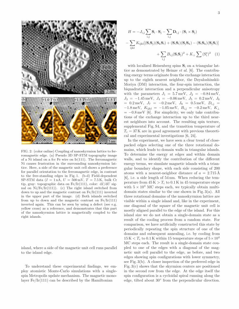
The island edges select the adjacent rotational do-mains, despite the resulting energy cost for domain wallformation due to frustration in the interior of the island.To investigate the impact of edge properties onto thenanoskyrmion lattice, we modify the boundary conditionfrom open to ferromagnetic. To that end, we preparedatomic layer Ni islands on fcc Fe/Ir(111) wires, which areferromagnetic with an out-of-plane easy axis [23]. The ef-fect of such an island onto the surrounding skyrmion lat-tice can be seen in Fig. 2(a). Small domains are formed inthe island’s vicinity, with a side of the magnetic unit celloriented parallel to the island edge. These orientationsare distinct from the three observed in Fe wires and is-lands in Fig. 1. The coupling of the skyrmion lattice canbe demonstrated directly by switching the NiFe islands inan external magnetic field: between Fig. 2(b) and (c) theright island is switched from down to up by increasing theexternal field from +1T to +1.5T. This is accompaniedby magnetic contrast inversion of the skyrmion lattice inthe upper half of the image. Switching both islands fromup to down in Fig. 2(d) also switches the skyrmion latticeback to a state like in Fig. 2(b). The skyrmion lattice inthe upper part of the image is thus coupled to the right
3
5 nm
(a)
(b) (c) (d)
5 nm
+1.0 T +1.5 T -1.5 T
Ni/Fe
Ni/Ir
Fe/Ir
FIG. 2: (color online) Coupling of nanoskyrmion lattice to fer-romagnetic edge. (a) Pseudo 3D SP-STM topography imageof a Ni island on a fcc Fe wire on Ir(111). The ferromagneticNi causes frustration in the surrounding nanoskyrmion lat-tice. Here, a side of the magnetic unit cell shows a preferencefor parallel orientation to the ferromagnetic edge, in contrastto the free-standing edges in Fig. 1. (b-d) Field-dependentSP-STM data (I = 1nA, U = 500mV, T = 7.5K, bulk Crtip, gray: topographic data on Fe/Ir(111), color: dI/dU sig-nal on Ni/Fe/Ir(111)). (c) The right island switched fromdown to up and the magnetic contrast on Fe/Ir(111) invertedin the upper part of the image. (d) Both islands switchedfrom up to down and the magnetic contrast on Fe/Ir(111)inverted again. This can be seen by using a defect (see e.g.yellow cross) as a reference, and demonstrates that this partof the nanoskyrmion lattice is magnetically coupled to theright islands.
island, where a side of the magnetic unit cell runs parallelto the island edge.
To understand these experimental findings, we em-ploy atomistic Monte-Carlo simulations with a single-spin Metropolis update mechanism. The magnetic mono-layer Fe/Ir(111) can be described by the Hamiltonian
H = −Ji,j∑
i,j
Si · Sj −
∑
i,j
Di,j · (Si × Sj)
−
∑
ijkl
Kijkl[(SiSj)(SkSl) + (SiSl)(SjSk)− (SiSk)(SjSl)]
+∑
i,j
Bi,j(SiSj)2 +K⊥
∑(Szi )
2 (1)
with localized Heisenberg spins Si on a triangular lat-tice as demonstrated by Heinze et al. [6]. The contribu-ting energy terms originate from the exchange interactionup to the eighth nearest neighbor, the Dzyaloshinskii-Moriya (DM) interaction, the four-spin interaction, thebiquadratic interaction and a perpendicular anisotropywith the parameters J1 = 5.7meV, J2 = −0.84meV,J3 = −1.45meV, J4 = −0.06meV, J5 = 0.2meV, J6= 0.2meV, J7 = −0.2meV, J8 = 0.5meV, Di,j =−1.8meV, Kijkl = −1.05meV, Bi,j = −0.2meV, K⊥
= −0.8meV [6]. For simplicity, we only take contribu-tions of the exchange interaction up to the third near-est neighbors into account. The resulting spin texture,supplemental Fig. S4, and the transition temperature ofTc = 37K are in good agreement with previous theoreti-cal and experimental investigations [6, 24].In the experiment, we have seen a clear trend of close-
packed edges selecting one of the three rotational do-mains, which leads to domain walls in triangular islands.To determine the energy at edges and within domainwalls, and to identify the contribution of the differentenergy terms, we simulate magnetic islands with a trian-gular boundary shape, with each side consisting of 200atoms with a nearest-neighbor distance of a = 2.715 A[6], i.e. a side length of 54 nm. When reducing the tem-perature from 45K > Tc to 0.1K in 45 temperature stepswith 5 × 10⁴ MC steps each, we typically obtain multi-domain states similar to the one shown in Fig. 3(a). Allthree rotational domains of the nanoskyrmion lattice arevisible within a single island and, like in the experiment,one diagonal of the square of the magnetic unit cell ismostly aligned parallel to the edge of the island. For thisisland size we do not obtain a single-domain state as aresult of the cooling process from a random state. Forcomparison, we have artificially constructed this state byperiodically repeating the spin structure of one of thedomains and subsequent annealing, i.e. by cooling from15K < Tc to 0.1K within 15 temperature steps of 5×10⁴
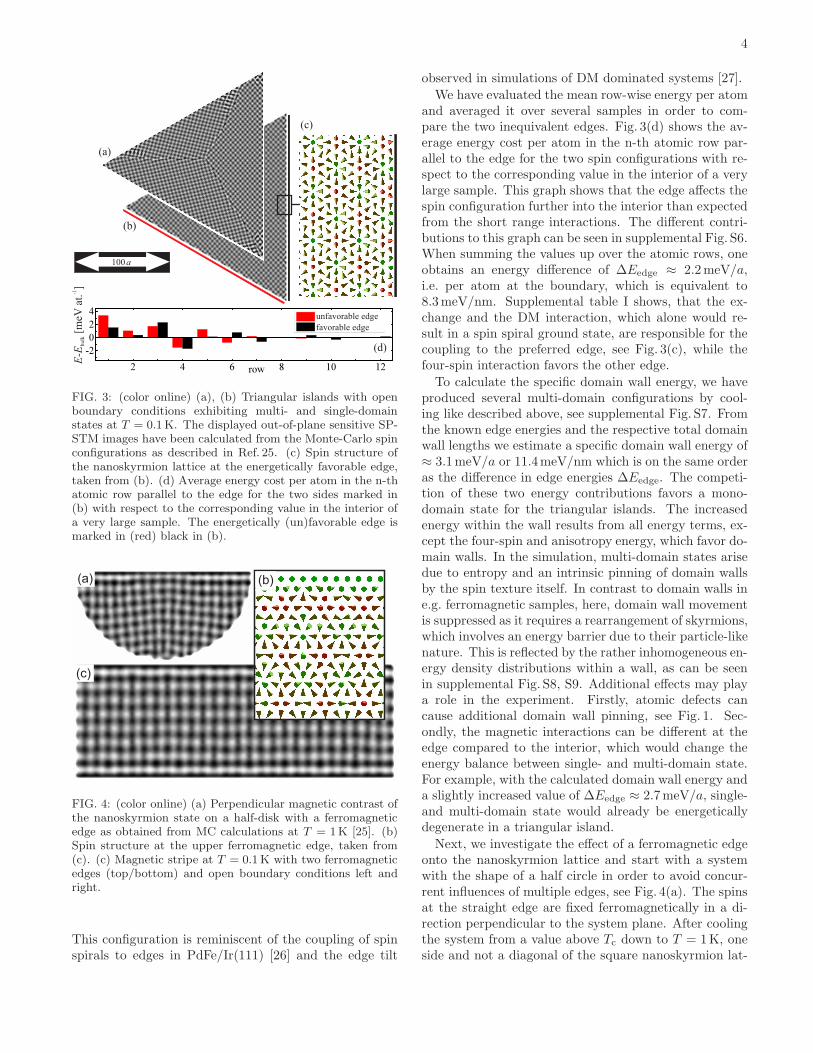
MC steps each. The result is a single-domain state cou-pled to one of the edges with a diagonal of the mag-netic unit cell parallel to the edge, as before, and twoedges showing spin configurations with lower symmetry,see Fig. 3(b). A closer inspection of the preferred edge inFig. 3(c) shows that the skyrmion centers are positionedin the second row from the edge. At the edge itself thespin configuration is a cycloidal spiral running along theedge, tilted about 30◦ from the perpendicular direction.
4
(c)
(a)
(b)
(d)
EE-
[meV
at.
]b
ulk
-1
unfavorable edge
favorable edge
100 a
FIG. 3: (color online) (a), (b) Triangular islands with openboundary conditions exhibiting multi- and single-domainstates at T = 0.1K. The displayed out-of-plane sensitive SP-STM images have been calculated from the Monte-Carlo spinconfigurations as described in Ref. 25. (c) Spin structure ofthe nanoskyrmion lattice at the energetically favorable edge,taken from (b). (d) Average energy cost per atom in the n-thatomic row parallel to the edge for the two sides marked in(b) with respect to the corresponding value in the interior ofa very large sample. The energetically (un)favorable edge ismarked in (red) black in (b).
(a)
(c)
(b)
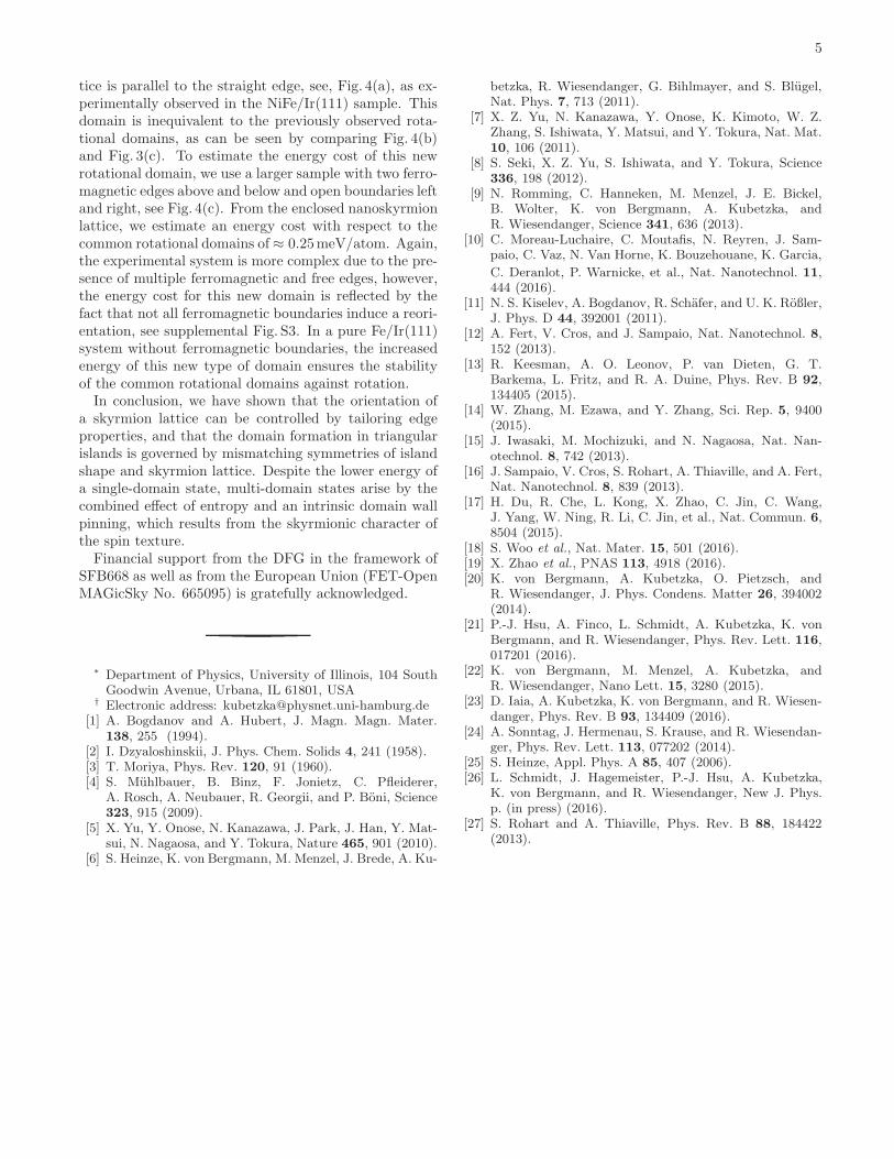
FIG. 4: (color online) (a) Perpendicular magnetic contrast ofthe nanoskyrmion state on a half-disk with a ferromagneticedge as obtained from MC calculations at T = 1K [25]. (b)Spin structure at the upper ferromagnetic edge, taken from(c). (c) Magnetic stripe at T = 0.1K with two ferromagneticedges (top/bottom) and open boundary conditions left andright.
This configuration is reminiscent of the coupling of spinspirals to edges in PdFe/Ir(111) [26] and the edge tilt
observed in simulations of DM dominated systems [27].
We have evaluated the mean row-wise energy per atomand averaged it over several samples in order to com-pare the two inequivalent edges. Fig. 3(d) shows the av-erage energy cost per atom in the n-th atomic row par-allel to the edge for the two spin configurations with re-spect to the corresponding value in the interior of a verylarge sample. This graph shows that the edge affects thespin configuration further into the interior than expectedfrom the short range interactions. The different contri-butions to this graph can be seen in supplemental Fig. S6.When summing the values up over the atomic rows, oneobtains an energy difference of ∆Eedge ≈ 2.2meV/a,i.e. per atom at the boundary, which is equivalent to8.3meV/nm. Supplemental table I shows, that the ex-change and the DM interaction, which alone would re-sult in a spin spiral ground state, are responsible for thecoupling to the preferred edge, see Fig. 3(c), while thefour-spin interaction favors the other edge.
To calculate the specific domain wall energy, we haveproduced several multi-domain configurations by cool-ing like described above, see supplemental Fig. S7. Fromthe known edge energies and the respective total domainwall lengths we estimate a specific domain wall energy of≈ 3.1meV/a or 11.4meV/nm which is on the same orderas the difference in edge energies ∆Eedge. The competi-tion of these two energy contributions favors a mono-domain state for the triangular islands. The increasedenergy within the wall results from all energy terms, ex-cept the four-spin and anisotropy energy, which favor do-main walls. In the simulation, multi-domain states arisedue to entropy and an intrinsic pinning of domain wallsby the spin texture itself. In contrast to domain walls ine.g. ferromagnetic samples, here, domain wall movementis suppressed as it requires a rearrangement of skyrmions,which involves an energy barrier due to their particle-likenature. This is reflected by the rather inhomogeneous en-ergy density distributions within a wall, as can be seenin supplemental Fig. S8, S9. Additional effects may playa role in the experiment. Firstly, atomic defects cancause additional domain wall pinning, see Fig. 1. Sec-ondly, the magnetic interactions can be different at theedge compared to the interior, which would change theenergy balance between single- and multi-domain state.For example, with the calculated domain wall energy anda slightly increased value of ∆Eedge ≈ 2.7meV/a, single-and multi-domain state would already be energeticallydegenerate in a triangular island.
Next, we investigate the effect of a ferromagnetic edgeonto the nanoskyrmion lattice and start with a systemwith the shape of a half circle in order to avoid concur-rent influences of multiple edges, see Fig. 4(a). The spinsat the straight edge are fixed ferromagnetically in a di-rection perpendicular to the system plane. After coolingthe system from a value above Tc down to T = 1K, oneside and not a diagonal of the square nanoskyrmion lat-
5
tice is parallel to the straight edge, see, Fig. 4(a), as ex-perimentally observed in the NiFe/Ir(111) sample. Thisdomain is inequivalent to the previously observed rota-tional domains, as can be seen by comparing Fig. 4(b)and Fig. 3(c). To estimate the energy cost of this newrotational domain, we use a larger sample with two ferro-magnetic edges above and below and open boundaries leftand right, see Fig. 4(c). From the enclosed nanoskyrmionlattice, we estimate an energy cost with respect to thecommon rotational domains of≈ 0.25meV/atom. Again,the experimental system is more complex due to the pre-sence of multiple ferromagnetic and free edges, however,the energy cost for this new domain is reflected by thefact that not all ferromagnetic boundaries induce a reori-entation, see supplemental Fig. S3. In a pure Fe/Ir(111)system without ferromagnetic boundaries, the increasedenergy of this new type of domain ensures the stabilityof the common rotational domains against rotation.In conclusion, we have shown that the orientation of
a skyrmion lattice can be controlled by tailoring edgeproperties, and that the domain formation in triangularislands is governed by mismatching symmetries of islandshape and skyrmion lattice. Despite the lower energy ofa single-domain state, multi-domain states arise by thecombined effect of entropy and an intrinsic domain wallpinning, which results from the skyrmionic character ofthe spin texture.Financial support from the DFG in the framework of
SFB668 as well as from the European Union (FET-OpenMAGicSky No. 665095) is gratefully acknowledged.
∗ Department of Physics, University of Illinois, 104 SouthGoodwin Avenue, Urbana, IL 61801, USA
† Electronic address: [email protected][1] A. Bogdanov and A. Hubert, J. Magn. Magn. Mater.
138, 255 (1994).[2] I. Dzyaloshinskii, J. Phys. Chem. Solids 4, 241 (1958).[3] T. Moriya, Phys. Rev. 120, 91 (1960).[4] S. Muhlbauer, B. Binz, F. Jonietz, C. Pfleiderer,
A. Rosch, A. Neubauer, R. Georgii, and P. Boni, Science323, 915 (2009).
[5] X. Yu, Y. Onose, N. Kanazawa, J. Park, J. Han, Y. Mat-sui, N. Nagaosa, and Y. Tokura, Nature 465, 901 (2010).
[6] S. Heinze, K. von Bergmann, M. Menzel, J. Brede, A. Ku-
betzka, R. Wiesendanger, G. Bihlmayer, and S. Blugel,Nat. Phys. 7, 713 (2011).
[7] X. Z. Yu, N. Kanazawa, Y. Onose, K. Kimoto, W. Z.Zhang, S. Ishiwata, Y. Matsui, and Y. Tokura, Nat. Mat.10, 106 (2011).
[8] S. Seki, X. Z. Yu, S. Ishiwata, and Y. Tokura, Science336, 198 (2012).
[9] N. Romming, C. Hanneken, M. Menzel, J. E. Bickel,B. Wolter, K. von Bergmann, A. Kubetzka, andR. Wiesendanger, Science 341, 636 (2013).
[10] C. Moreau-Luchaire, C. Moutafis, N. Reyren, J. Sam-paio, C. Vaz, N. Van Horne, K. Bouzehouane, K. Garcia,
C. Deranlot, P. Warnicke, et al., Nat. Nanotechnol. 11,444 (2016).
[11] N. S. Kiselev, A. Bogdanov, R. Schafer, and U. K. Roßler,J. Phys. D 44, 392001 (2011).
[12] A. Fert, V. Cros, and J. Sampaio, Nat. Nanotechnol. 8,152 (2013).
[13] R. Keesman, A. O. Leonov, P. van Dieten, G. T.Barkema, L. Fritz, and R. A. Duine, Phys. Rev. B 92,134405 (2015).
[14] W. Zhang, M. Ezawa, and Y. Zhang, Sci. Rep. 5, 9400(2015).
[15] J. Iwasaki, M. Mochizuki, and N. Nagaosa, Nat. Nan-otechnol. 8, 742 (2013).
[16] J. Sampaio, V. Cros, S. Rohart, A. Thiaville, and A. Fert,Nat. Nanotechnol. 8, 839 (2013).
[17] H. Du, R. Che, L. Kong, X. Zhao, C. Jin, C. Wang,J. Yang, W. Ning, R. Li, C. Jin, et al., Nat. Commun. 6,8504 (2015).
[18] S. Woo et al., Nat. Mater. 15, 501 (2016).[19] X. Zhao et al., PNAS 113, 4918 (2016).[20] K. von Bergmann, A. Kubetzka, O. Pietzsch, and
R. Wiesendanger, J. Phys. Condens. Matter 26, 394002(2014).
[21] P.-J. Hsu, A. Finco, L. Schmidt, A. Kubetzka, K. vonBergmann, and R. Wiesendanger, Phys. Rev. Lett. 116,017201 (2016).
[22] K. von Bergmann, M. Menzel, A. Kubetzka, andR. Wiesendanger, Nano Lett. 15, 3280 (2015).
[23] D. Iaia, A. Kubetzka, K. von Bergmann, and R. Wiesen-danger, Phys. Rev. B 93, 134409 (2016).
[24] A. Sonntag, J. Hermenau, S. Krause, and R. Wiesendan-ger, Phys. Rev. Lett. 113, 077202 (2014).
[25] S. Heinze, Appl. Phys. A 85, 407 (2006).[26] L. Schmidt, J. Hagemeister, P.-J. Hsu, A. Kubetzka,
K. von Bergmann, and R. Wiesendanger, New J. Phys.p. (in press) (2016).
[27] S. Rohart and A. Thiaville, Phys. Rev. B 88, 184422(2013).


![Fig.6_taue 6_Fig_taue: Energy confinement times form the ISS95 [24] scaling vs. experimental confinement times. The colored data indicate contributions to](https://img.pdfslide.us/doc/110x75/56649c715503460f949223d9/fig6taue-6figtaue-energy-connement-times-form-the-iss95-24-scaling.jpg)


![Skyrmions with low binding energies · 2015. 8. 11. · in spherical polar coordinates. Previous phenomenological studies of BPS [5,8,9] and near-BPS [10,11] skyrmions have all been](https://img.pdfslide.us/doc/110x75/613884d70ad5d20676494d75/skyrmions-with-low-binding-energies-2015-8-11-in-spherical-polar-coordinates.jpg)