Embed Size (px)
Citation preview

1 of 9
Sky Sensor Installation
OPERATION MANUALQDM-05-000045
Rev 5 | July 2019 ©2019 View, Inc.
Product DescriptionThe roof-mounted Sky Sensor provides external light level data and infrared temperature data to the View system to allow optimization of tint levels for each zone. The assembly includes the Sky Sensor with a 50 ft length of CAT5 Ethernet cable attached.
Package Includes1. Sky Sensor Body.2. Sky Sensor Base.3. 50 ft length of CAT5 plenum rated Ethernet cable with an RJ45 pre-terminated.4. PN: 015-102018 L-com Wireless Indoor Shielded CAT6 Surge Protector (POE
Coupler) Model: HGLN-CAT6J (Ships in Separate box).
Additional Supporting Documentation1. Sky Sensor Data Sheet - QDM-02-000062.2. CAT5 Termination Procedure - https://www.l-com.com/multimedia/manuals/
M_ECRA_SERIES.PDF.3. For CP 3.0, POE cable can be connected to Advantech POE switch (see CP 3.0 Data
sheet for port options).4. Data Sheet for L-Com POE Coupler: http://www.l-com.com/multimedia/datasheets/
DS_HGLN-CAT6J.PDF.
PoE Injector requirements1. For systems with Control Panel 2.0, use PoE injector with P/N: 015-101821-01.2. For systems with older Control Panel, use PoE injector with P/N: 330-101504.3. For CP 3.0, POE cable can be connected to Advantech POE switch (see CP 3.0 Data
sheet for port options).
Tools and Materials required1. Conduit (RMT or IMT) for roof mast.2. #2 Phillips screwdriver.
Sky Sensor Body
Sky Sensor Base
2 of 9
Sky Sensor Installation
OPERATION MANUALQDM-05-000045
Rev 5 | July 2019 ©2019 View, Inc.
System Requirements The Sky Sensor communicates to the View system and receives power via Power-over- Ethernet (PoE) utilizing midspan Power Injector.
1. PoE voltage requirements: Class 0, 36 - 57 VDC. Powering device should be Type 1 and not higher.
2. Category CAT5 or above.3. Maximum cable segment length is 328 feet (100 meters).
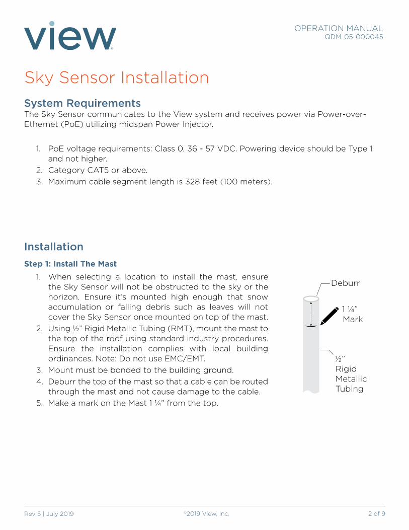
InstallationStep 1: Install The Mast
1. When selecting a location to install the mast, ensure the Sky Sensor will not be obstructed to the sky or the horizon. Ensure it’s mounted high enough that snow accumulation or falling debris such as leaves will not cover the Sky Sensor once mounted on top of the mast.
2. Using ½” Rigid Metallic Tubing (RMT), mount the mast to the top of the roof using standard industry procedures. Ensure the installation complies with local building ordinances. Note: Do not use EMC/EMT.
3. Mount must be bonded to the building ground.4. Deburr the top of the mast so that a cable can be routed
through the mast and not cause damage to the cable.5. Make a mark on the Mast 1 ¼” from the top.
1 ¼”
½”Rigid Metallic Tubing
Mark
Deburr

3 of 9
Sky Sensor Installation
OPERATION MANUALQDM-05-000045
Rev 5 | July 2019 ©2019 View, Inc.
Step 2: Feed CAT5 wire through mast1. Feed the CAT5 ethernet cable down the mast into the building space.
Step 3: Install Sky Sensor Base1. Using a Phillips head screw driver, loosen the three set screws at the base of the Sky
Sensor. This will allow you to slide the base down onto the mast.
2. Slide the Sky Sensor base down onto the mast and ensure the bottom of the Sky Sensor Base lines up with the mark that you made 1 ¼” from the top. If the two align, this indicates that the Mast is fully inserted into the Sky Sensor.
3. Hand tighten the three set screws until firmly secured to the mast. Note: Do not over tighten and strip the screws. Do not use power tools.
1
2
3
Sky Sensor Base and mark should align

4 of 9
Sky Sensor Installation
OPERATION MANUALQDM-05-000045
Rev 5 | July 2019 ©2019 View, Inc.
Step 4: Route the Ethernet CableNote: Do not remove the dust cap from the end of the Ethernet cable at this time.
1. Use caution to ensure you don’t damage the RJ45connector and insert the RJ45 end of 50-ft CAT5 Ethernet cable into and the mast until the end of the cable with the dust cap is sitting inside the Sky Sensor Base on top of the mast.
2. Using standard CAT5 coupler with standard Ethernet tester, confirm Ethernet is working.
1
2
3
5 of 9
Sky Sensor Installation
OPERATION MANUALQDM-05-000045
Rev 5 | July 2019 ©2019 View, Inc.
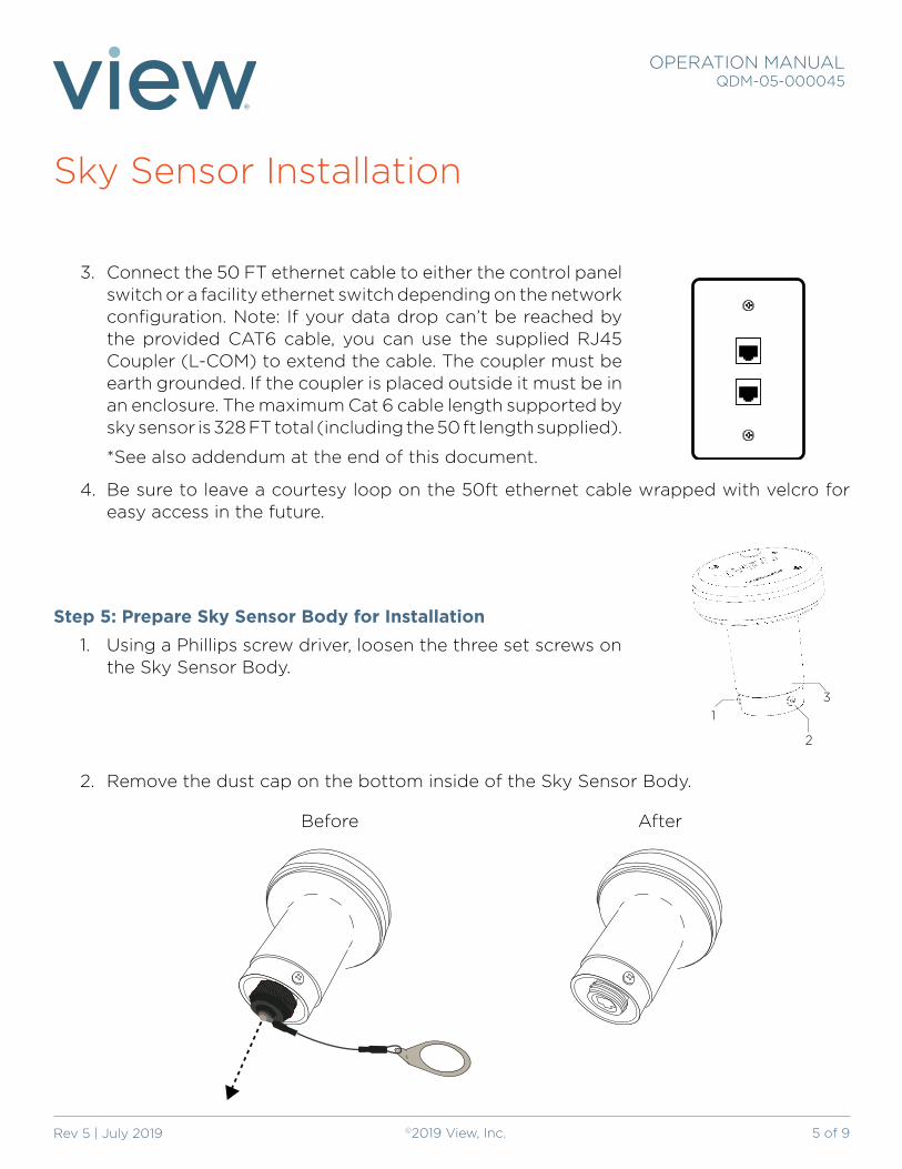
3. Connect the 50 FT ethernet cable to either the control panel switch or a facility ethernet switch depending on the network configuration. Note: If your data drop can’t be reached by the provided CAT6 cable, you can use the supplied RJ45 Coupler (L-COM) to extend the cable. The coupler must be earth grounded. If the coupler is placed outside it must be in an enclosure. The maximum Cat 6 cable length supported by sky sensor is 328 FT total (including the 50 ft length supplied).
*See also addendum at the end of this document.
4. Be sure to leave a courtesy loop on the 50ft ethernet cable wrapped with velcro for easy access in the future.
Step 5: Prepare Sky Sensor Body for Installation1. Using a Phillips screw driver, loosen the three set screws on
the Sky Sensor Body.
2. Remove the dust cap on the bottom inside of the Sky Sensor Body.
1
2
3
Before After

6 of 9
Sky Sensor Installation
OPERATION MANUALQDM-05-000045
Rev 5 | July 2019 ©2019 View, Inc.
Step 6: Connect Data Cable to Sky Sensor1. Remove the dust cap from the CAT5 Ethernet cable inside the Sky Sensor Base on the
mast.2. Align the RJ 45 connector and the keying feature (see below) and small hole on the
bottom of the Sky Sensor. Once aligned, carefully press the two together and hand-tighten the black colored sleeve securely to the base of the Sky Sensor.
3. Ensure the mid span injector is installed and then test the sensor connectivity by connecting your laptop to the “network” (vs “network + power”) side of the midspan injector. This test can also be done from the control panel by plugging a laptop into one of the available Ethernet jacks on the top of the control panel (any jack other than J17).
Step 7: Mount the Sky Sensor to the Base1. With the RJ45 connected to
the Sky Sensor, place it onto the Sky Sensor Base.
Keying Feature Sealing Surface
1.38[34.9]
7 of 9
Sky Sensor Installation
OPERATION MANUALQDM-05-000045
Rev 5 | July 2019 ©2019 View, Inc.
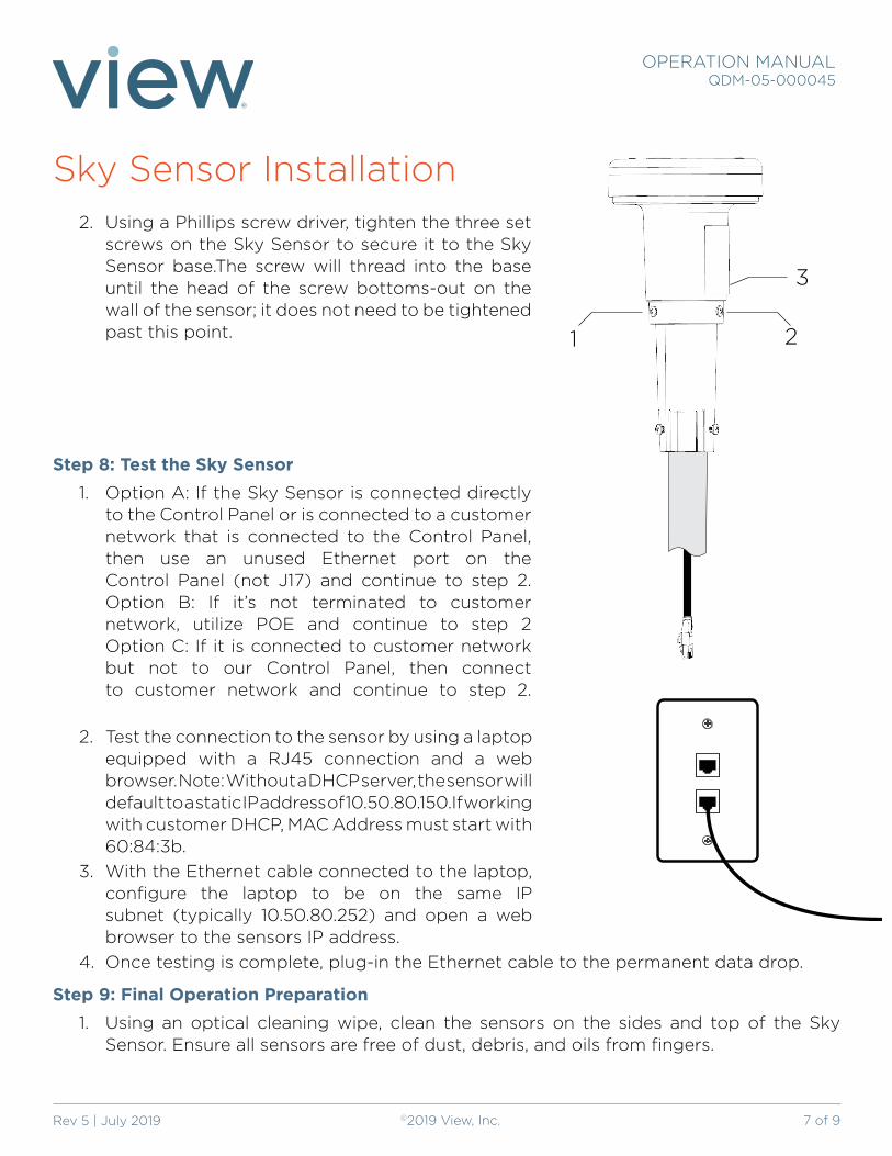
2. Using a Phillips screw driver, tighten the three set screws on the Sky Sensor to secure it to the Sky Sensor base.The screw will thread into the base until the head of the screw bottoms-out on the wall of the sensor; it does not need to be tightened past this point.
Step 8: Test the Sky Sensor1. Option A: If the Sky Sensor is connected directly
to the Control Panel or is connected to a customer network that is connected to the Control Panel, then use an unused Ethernet port on the Control Panel (not J17) and continue to step 2. Option B: If it’s not terminated to customer network, utilize POE and continue to step 2 Option C: If it is connected to customer network but not to our Control Panel, then connect to customer network and continue to step 2.
2. Test the connection to the sensor by using a laptop equipped with a RJ45 connection and a web browser. Note: Without a DHCP server, the sensor will default to a static IP address of 10.50.80.150.If working with customer DHCP, MAC Address must start with 60:84:3b.
3. With the Ethernet cable connected to the laptop, configure the laptop to be on the same IP subnet (typically 10.50.80.252) and open a web browser to the sensors IP address.
4. Once testing is complete, plug-in the Ethernet cable to the permanent data drop.
Step 9: Final Operation Preparation1. Using an optical cleaning wipe, clean the sensors on the sides and top of the Sky
Sensor. Ensure all sensors are free of dust, debris, and oils from fingers.
3
21
8 of 9
Sky Sensor Installation
OPERATION MANUALQDM-05-000045
Rev 5 | July 2019 ©2019 View, Inc.
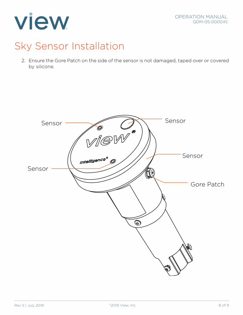
2. Ensure the Gore Patch on the side of the sensor is not damaged, taped over or covered by silicone.
Sensor
Sensor
Sensor
Sensor
Gore Patch

9 of 9
Sky Sensor Installation
OPERATION MANUALQDM-05-000045
Rev 5 | July 2019 ©2019 View, Inc.
Addendum - Sky Sensor Grounding Coupler Installation
This document covers installation of the LCOM Part Number HGLN-CAT6J Lightning Protector when site conditions prevent the 50-foot cable provided with the Sky Sensor to directly terminate to the View control panel.
Introduction The View Sky Sensor is provided with a 50-foot shielded twisted pair (STP) RG6 Ethernet cable to connect the sensor to the control panel. In the case where the Sky Sensor cable does not directly connect to the control panel, then a ground coupler should be used.
ProcedureRefer to the picture:
• The two Ethernet jacks on the top of the protector are not specific, the cable from the Sky Sensor can be plugged into either of the jacks.
• Mount the protector to a solid object, a wall or Telecom rack with the four mounting ears and suitable self-tapping screws.
• Crimp the provided ring lug on a suitable length (site specific) 14AWG THHN green or green/yellow wire (not provided by View) to bond the protector to a designated earth ground. Typically, telecom racks used in data closets are grounded, as are conduit fitting and boxes. If there is any doubt on the proper facility ground point, consult with the electrician on site.
• Connect the View provided Sky Sensor cable to one of the RJ45 jacks.
• Connect the extension Ethernet CAT6 cable (UTP or STP) to the other port on the protector and then to the View control panel.
• Verify connectivity of the sensor to the panel.