Embed Size (px)
Citation preview

1.

2. Need help with Ladder logic problem!

3.


4.
5. Design a three - bit free running counter which counts 3, 4, 5, 3, 4, 5, .... Use the circuit in Figure 5.25 (a) of the textbook to design the circuit. You may have add asynchronous Preset/Clear inputs to Figure 5.25 (a) to initialize/load the first count . Draw the timing diagram similar to Figure 5.25 (b).

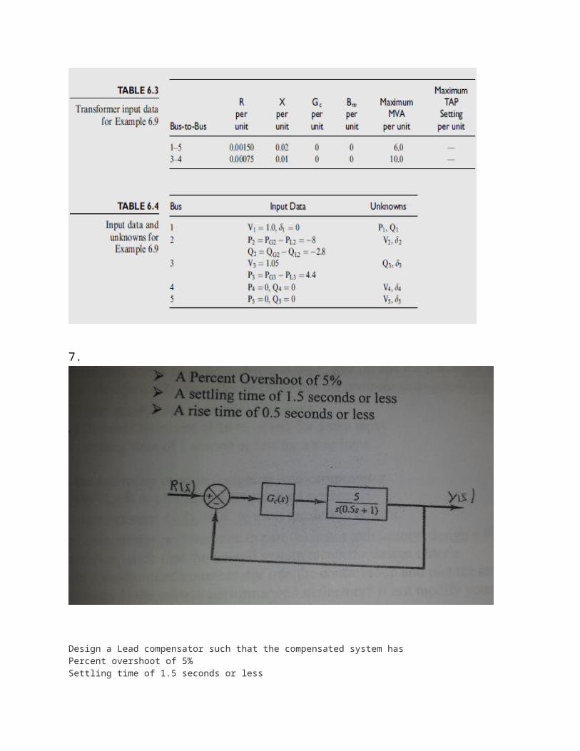
6. The single line diagram below shows a five bus power system. Input data are given in Tables 1, 2, and 3. As shown in Table 1, bus 1, to which a generator is connected, is the swing bus. Bus 3, to which a generator and a load are connected, is a voltage-controlled bus. Buses 2, 4, and 5 are load buses. Note that the loads at buses 2 and 3 are inductive since Q2 = -QL2= -2.8 and _-QL3= -0.4 are negative. For each bus k, determine which of the variables Vk, δk, Pk, and Qk are input data and which are unknowns. Also, compute the elements of Ybus.Use Gauss –Seidel method to calculate V2, the phasor voltage at bus 2 after the first iteration. Use zero initial phase angles and 1.0 per unit flat voltage profiles magnitudes at load buses to start the iteration procedure.

7.
Design a Lead compensator such that the compensated system has Percent overshoot of 5%Settling time of 1.5 seconds or lessRise time 0.5 seconds or lessPerform the following steps in designing the compensator

A. Use MATLAB to plot the uncompensated system(below is my current code for matlab the tf or transfer fuction is diffrent from this block diagram)for k = 1 PO=5. %Percent overshoot zx=(log(PO/100))^2; zeta=sqrt(zx/(pi^2+zx)) ts=1.5 %settling time in seconds wn=4/(zeta*ts); %tr 0.5= %rise time in seconds %wn=(0.16*zeta+0.6)/tr; %tp= %peak time in second %wn=pi/(tp*sqrt(1-zeta^2)); s = -zeta*wn+j*wn*sqrt(1-zeta^2) g = tf(4,[1 2 0]) h = tf([1],[1]) sysu=g*h; rlocus(sysu),title('root locus uncompensated system')% root locus of uncompensated system pause am = evalfr(sysu,s); ad = (180/pi)*angle(am); ag = 180-ad pause xl=imag(s)*tan((pi/180)*ag); xp=(imag(s)/tan((pi/180)*ag)) lead=tf([1 -real(s)],[1 -real(s)+xl]) pause pd=tf([1 -real(s)+xp],1) pause rlocus(sysu*lead),title('root locus compensated with lead') pause rlocus(sysu*pd),title('root locus compensated with PD') pause [kl pl]=rlocfind(sysu*lead,s); kl syscl = feedback(kl*sysu*lead,h); step(syscl),title('step response of compensated with lead') pause [kp pp]=rlocfind(sysu*pd,s); kp syscp = feedback(kp*sysu*pd,h); step(syscp),title('step response of compensated with PD') pause step(syscl,'-',syscp,'--'),legend('lead compensated','PD compensated')endB. Use a compensator Gc(s) =K to meet criteriaC If the compensator performance in part (b) is not satifsfactory, design a lead or lag compensator such that the overall system meet the design criteriaD Include your designed compensator into the control-loop and plot the step response of the closed -loop system. Is the system performance satisfactory? If not modify your compensator design and repeat part (a)E Realize your controller using Op-amps, resistors, and capacitors 8. As an entry-level engineer, you are assigned with a project to design a power transmission line. Here is the description and requirements of the transmission line:The transmission line is 500 miles long and needs to deliver a load of 5000 MVA with .8 power factor lagging. Receiving end voltage is 735 kV. a) Select a conductor type and transmission line arrangement with bundling option. Show your preferred diagram

b) Find R, L, and C of the linec) Fine the A, B, C, and D constant of the line using long-line model. Draw the equivalent pi-model of the lined) Find sending end current and voltagee) Find the efficiency of the linef) Calculate the series capacitor value per-phase to increase the power transfer capability of the line by 20%g) Calculate the shunt capacitor value per-phase at the receiving end to maintain the receiving end voltage at .96% of the sending end voltage at full loadh) The transmission requires to maintain Vs/Vr = .96 during the no-load condition. Calculate the required inductor value that needs to be connected in parallel at the receiving end.i) Draw the one-line transmission diagram (pi-model) with all compensation componentsj) Recalculate the efficiency of the line. Thank you!
9.

10.
11. Design a HLSM that computes the average temperature once every minutes. The temperature sensor sends out the temperature once every second. Show the datapath and state machine.
12. Please help

Solve analytically not numerically
Let

To make things easier
And for some calculations


![Bass Guitar, Bazouki Fiddlenelsonclub.co.uk/onewebmedia/26th APRIL 2016[1].pdfGuitar, Bazouki MICK BISIKER Fiddle NIGEL WARD Title Microsoft Word - 26th APRIL 2016[1].docx Created](https://img.pdfslide.us/doc/110x75/5b312f4c7f8b9a2c328c5065/bass-guitar-bazouki-april-20161pdfguitar-bazouki-mick-bisiker-fiddle-nigel.jpg)
![VERSAMID 115 Technical Data Sheet April 2016[5] · PDF fileTitle: Microsoft Word - VERSAMID 115 Technical Data Sheet April 2016[5].docx Created Date: 4/8/2016 6:29:46 PM](https://img.pdfslide.us/doc/110x75/5a7891417f8b9a273b8b47a7/versamid-115-technical-data-sheet-april-20165-title-microsoft-word-versamid.jpg)