Embed Size (px)
DESCRIPTION
Skin and Stimulation
Citation preview

Skin and Stimulation
• Skin? What does it mean?
• Types of skin – what is a barrier to production?
• Can it change with time?
• Prevention, removal or bypass?
8/25/2015 1 George E. King Engineering
GEKEngineering.com

Skin Effect
8/25/2015 2 George E. King Engineering
GEKEngineering.com

Skin Damage
8/25/2015 3 George E. King Engineering
GEKEngineering.com

F l o w R a t e , b p d
P I = 1 0 . 7 4 b / d / p s i
P I = 2 . 3 2 b / d / p s i
P w
1 0 0 0
8 0 0
6 0 0
4 0 0
2 0 0
1 0 0 0 2 0 0 0 3 0 0 0 4 0 0 0 5 0 0 0 6 0 0 0
I P R C u r v e
D p
Formation Damage/”Skin”
Productivity Index or “P.I.”
PI is a measure of the oil flow rate (bpd) that will be obtained for every 1 psi pressure drop in the reservoir
PI =
PI in stb/d/psi
Q
(Pr-Pw)
DP
“Drawdown”
8/25/2015 4 George E. King Engineering
GEKEngineering.com

Sources of “formation damage” that result in loss of production potential or “skin”.
• Particulates - Muds, debris in kill fluids, solids in acids, etc. Basically surface plugging of pores and fractures.
• Precipitates - Scales, paraffin (wax), asphaltenes – usually in the tubing, but sometimes in the formation.
• Clay/Mineral damage - Swelling / migration of clays / fines in the pores of the rock.
• Relative permeability effects - Wetting, emulsions and water blocks in the pores. • Inflow Problems - Limited perfs, lack of open hole, contact of wellbore to fracture,
well placement – these are well completion design issues. • Flow path blockages - Perf damage, tubular blockages, restrictions – these are
workover issues. • Flow problems based around limited entry, tortuosity and turbulence - • Pressures (Hydrostatic column weight, fluctuating water, loading, backpressures
from chokes, loading, treaters and pipelines).
8/25/2015 5 George E. King Engineering
GEKEngineering.com

Skin
• Elements of Skin • Perforation - penetration, entry hole size, phasing, limited
entry, and plugging.
• Stimulation - frac penetration, embedment, scaling, width problems, polymer damage
• Damage (mechanical) – issues with mud invasion,
• Damage Gravel Pack – polymer, fines, paraffin and scale.
• Well Geometry – how good is the reservoir-to-well- flowpath?
• Non-Darcy – turbulence is an often unseen restriction.
Well
8/25/2015 6 George E. King Engineering
GEKEngineering.com

Diagnostics- Build Up Tests or RTA – A first Clue to look
Storage
Permeability Indication
Skin
Fracture
Length Boundary
conditions
Normalized Delta P/Q and overlaying successive tests useful for trend analysis
Valhall compaction rate and ARE condensate effects, examples
Other Diagnostics (to understand skin) – Chemistry tests, samples, reservoir data
(core, etc) and logs, diagnostic logs, flowing surveys, fluid shots
8/25/2015 7 George E. King Engineering
GEKEngineering.com

Main Skin Components
• Mechanical
– Near wellbore mechanical effects
• Geometric (aka partial penetration, partial completion, or deviation)
– Effect of not completing through entire reservoir thickness
– Effect of not being vertical
• Position in the reservoir
– Productivity is affected by where well is and what it is near
• Stimulation
– Reducing pressure losses in the near wellbore region
• Non-Darcy (turbulent effects)
– Additional losses from high velocities in near wellbore region
• Pseudo
– Losses due to Relative Permeability & Condensate banking
8/25/2015 8 George E. King Engineering
GEKEngineering.com

Skin Components - Mechanical
• Damage
–drilling fluids, scale, salt etc.
• Gravel packs & screens
• Stimulation
8/25/2015 9 George E. King Engineering
GEKEngineering.com
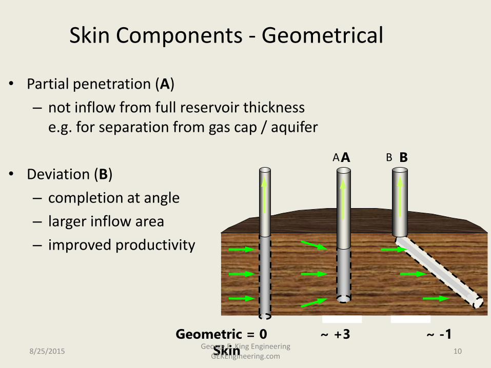
Skin Components - Geometrical
• Partial penetration (A)
– not inflow from full reservoir thickness e.g. for separation from gas cap / aquifer
• Deviation (B)
– completion at angle
– larger inflow area
– improved productivity
Geometric = 0 ~ +3 ~ -1 Skin
A B A B
8/25/2015 10 George E. King Engineering
GEKEngineering.com

Effect of position of well • Prod. affected by position relative to reservoir & no-flow boundaries: flow paths distorted
• Modelled in Prosper via Dietz Shape Factor
• Example for a vertical well with mechanical skin = 0:
Description Dietz-shape
Factor
Productivity
c.f. Ideal
Effective
Skin
Diagram of well
position c.f.
boundaries
Centre of cylindrical
reservoir (optimal
configuration)
31.6 100% 0
Centre of rectangular
reservoir of 2:1 aspect ratio
22.6 98% 0.17
Centre of rectangular
reservoir of 4:1 aspect ratio
5.4 89% 0.9
Offset to corner of
rectangular reservoir of 2:1
aspect ratio
2.1 84% 1.35
Offset in rectangular
reservoir of 2:1 aspect ratio
0.6 78% 2.0
Offset to corner of
rectangular reservoir of 4:1
aspect ratio
0.23 71% 2.5
Source unknown 8/25/2015 11
George E. King Engineering GEKEngineering.com

Formation Damage/”Skin” • “Skin”
– to understand “skin” we need to define IPR and see where the relationship to skin lies
This equation is known as the “Steady State Radial Flow Equation for Oil at a
Constant Reservoir Pressure”( i.e. Waterflood)
Qkh Pw
B Log r r Sn e w
0 00708. (Pr )
( { / } )
S = Skin - a dimensionless number
How do we
measure
“Skin”:?
8/25/2015 12 George E. King Engineering
GEKEngineering.com

Where is the skin? Why?
There can be positive and negative skins in different parts of the same well at one time. How much of the wellbore is really producing?
8/25/2015 13 George E. King Engineering
GEKEngineering.com

Formation Damage/”Skin” • Formation Damage - can be defined as “A reduction of permeability around a
wellbore, which is the consequence of drilling, completion, INTERVENTION, injection, attempted stimulation, or production of that well.”
Example showing pressure profile/drop and the effect of formation damage
600psi pressure drop in 8 inches
1300psi
1300psi
0
1000
2000
3000
4000
5000
6000
7000
1 100 1000
Pressure(psia)
Bottomhole flowingpressure 2500 psia
10
Reservoir Pressure7000psia
Notice the huge pressure drop in the last eight inches
around the wellbore. You can imagine how badly the
well productivity would be affected if this pressure
drop was even greater due to formation damage.
8/25/2015 14 George E. King Engineering
GEKEngineering.com

Effect on Skin on Production
0
500
1000
1500
2000
2500
3000
3500
0 5000 10000 15000
Oil Rate, stb/d
Bo
tto
m H
ole
Pre
ss
ure
, p
si
-5
0
+5
+10
+20+100
ho = 30 ft
ko = 100 md
uo = 0.5 cp
Bo = 1.5
rw = 0.35 ft
re = 1500 ft
Pr = 3000 psi
Source - BP Exploration
Completion Design Manual
Effect of Skin on Well Productivity
8/25/2015 15 George E. King Engineering
GEKEngineering.com

Skin effect on production (when the well is not otherwise constrained or in communication), has its maximum influence to about 15 to 20. Higher skins decrease production but not at the rate of change as skin drops from 0 to about 15.
8/25/2015 16 George E. King Engineering
GEKEngineering.com

Formation Damage/”Skin” Impact
• “Skin” Factors
A negative skin factor means that productivity is higher than the zero skin case
A positive skin factor means that the productivity is lower than the zero skin case
SKIN RATE (BPD)
-6
-3
-1
0
+2
+4
+8
+24
+100
80,000
32,000
22,857
20,000
16,000
13,333
10,000
5,000
1,481
increasing stimulation
‘(ideal)’ no damage
increasing damage
Note that skin can be positive to infinity, but negative to
about -6, possibly -7. The theoretical minimum is -8.
8/25/2015 17 George E. King Engineering
GEKEngineering.com

Wellwork Candidate Selection
• The Concept – what do you want to do?
• What do you need to do it?
• How to find the clues. What the clues mean.
• What are the barriers?
• How to select the best candidate.
• How to put it to work.
• Analyzing how it went.
8/25/2015 18 George E. King Engineering
GEKEngineering.com

Formation Damage/”Skin”
• Flow Efficiency
– can give a more useful idea for the effect of damage on flowrates
The flow rates, corresponding to actual and zero skins, must be
measured at the same drawdown.
Flow Efficiency =
=
=
Flow rate with actual skin Flow rate with zero skin
Log (re/rw)
Log (re/rw) + S
8 8 + S
n
n
(to a good approximation)
Note: Care is needed with the flow efficiency approximation – skin effect on production is not linear over a broad range and removal of skins may not increase the production if the well is lift limited, tubing limited, facility limited, restrained by regulation, or when the well’s fluids are being produced by another well (communication).
8/25/2015 19 George E. King Engineering
GEKEngineering.com

Skin Development – Skin is not static!
8/25/2015 20 George E. King Engineering
GEKEngineering.com

What completion, sand control and stimulation are best? The reservoir dictates the terms.
At extremely high formation k and q, perforations are chokes on flow. 12 spf (40 spm) , 0.75” (1.8 cm) holes open only about 2% of the casing wall.
8/25/2015 21 George E. King Engineering
GEKEngineering.com


![Mécano-stimulation™ of the skin improves sagging score and ... · metalloproteinases [TIMPs]). A new device providing a mechanical stimulation of the cutaneous and subcutaneous](https://img.pdfslide.us/doc/110x75/5e91828aa385c15abe7790ac/mcano-stimulationa-of-the-skin-improves-sagging-score-and-metalloproteinases.jpg)