Embed Size (px)
Citation preview

OP
ER
AT
OR
'S M
AN
UA
L
MC
PLF
A
SKID STEERCOLD PLANER
CP12LFA12" Low Flow “A” Series
Effective Serial Numbers:242340201 & Above
Rev
. 7/4
/200
8
Tested. Proven. Unbeatable.

2 Introduction CE Construction (Rev. 7/20/2007)
TO THE DEALER:
Assembly and proper installation of this product is the responsibility of the Woods® dealer. Read manual instructionsand safety rules. Make sure all items on the Dealer’s Pre-Delivery and Delivery Check Lists in the Operator’s Manualare completed before releasing equipment to the owner.
The dealer must complete the Product Registration included with the Operator’s Manual. The customer must sign theregistration which certifies that all Dealer Check List items have been completed. The dealer is to return the prepaidpostage portion to Woods, give one copy to the customer, and retain one copy. Failure to complete and return thiscard does not diminish customer’s warranty rights.
TO THE OWNER:
Read this manual before operating your Woods equipment. The information presented will prepare you to do a better andsafer job. Keep this manual handy for ready reference. Require all operators to read this manual carefully and becomeacquainted with all adjustment and operating procedures before attempting to operate. Replacement manuals can beobtained from your dealer. To locate your nearest dealer, check the Dealer Locator at www.WoodsEquipment.com, or inthe United States and Canada call 1-800-848-3447.
The equipment you have purchased has been carefully engineered and manufactured to provide dependable andsatisfactory use. Like all mechanical products, it will require cleaning and upkeep. Lubricate the unit as specified.Observe all safety information in this manual and safety decals on the equipment.
For service, your authorized Woods dealer has trained mechanics, genuine Woods service parts, and the necessarytools and equipment to handle all your needs.
Use only genuine Woods service parts. Substitute parts will void the warranty and may not meet standards required forsafe and satisfactory operation. Record the model number and serial number of your equipment in the spacesprovided:
Model: _______________________________ Date of Purchase: _____________________
Serial Number: (see Safety Decal section for location) ____________________________________
Provide this information to your dealer to obtain correct repair parts.
Throughout this manual, the term NOTICE is used to indicate that failure to observe can cause damage to equipment.The terms CAUTION, WARNING, and DANGER are used in conjunction with the Safety-Alert Symbol (a triangle withan exclamation mark) to indicate the degree of hazard for items of personal safety.
Introduction 3MCPLFA (Rev. 6/23/2006)
TABLE OF CONTENTS
INTRODUCTION. . . . . . . . . . . . . . . . . . . . . . . . . . . . . . . . . . . . . . . . . . . . . . .2
GENERAL INFORMATION . . . . . . . . . . . . . . . . . . . . . . . . . . . . . . . . . . . . . . .4
SPECIFICATIONS. . . . . . . . . . . . . . . . . . . . . . . . . . . . . . . . . . . . . . . . . . . . . .4
SAFETY RULES . . . . . . . . . . . . . . . . . . . . . . . . . . . . . . . . . . . . . . . . . . . . . . .5
SAFETY DECALS . . . . . . . . . . . . . . . . . . . . . . . . . . . . . . . . . . . . . . . . . . . . . .8
OPERATION . . . . . . . . . . . . . . . . . . . . . . . . . . . . . . . . . . . . . . . . . . . . . . . . .10
TROUBLE SHOOTING . . . . . . . . . . . . . . . . . . . . . . . . . . . . . . . . . . . . . . . . .14
SERVICE. . . . . . . . . . . . . . . . . . . . . . . . . . . . . . . . . . . . . . . . . . . . . . . . . . . .16
PARTS LISTS . . . . . . . . . . . . . . . . . . . . . . . . . . . . . . . . . . . . . . . . . . . . . . . .24
FITTING TORQUE CHART. . . . . . . . . . . . . . . . . . . . . . . . . . . . . . . . . . . . . .35
BOLT TORQUE CHART . . . . . . . . . . . . . . . . . . . . . . . . . . . . . . . . . . . . . . . .39
BOLT SIZE CHART. . . . . . . . . . . . . . . . . . . . . . . . . . . . . . . . . . . . . . . . . . . .40
INDEX . . . . . . . . . . . . . . . . . . . . . . . . . . . . . . . . . . . . . . . . . . . . . . . . . . . . . .41
PRODUCT WARRANTY . . . . . . . . . . . . . . . . . . . . . . . . . . . . . . . . . . . . . . . .42
REPLACEMENT PARTS WARRANTY . . . . . . . . . . . . INSIDE BACK COVER
Si no lee Ingles, pida ayuda a alguien que si lo lea para que le
traduzca las medidas de seguridad.
LEA EL INSTRUCTIVO!!
4 Introduction MCPLFA (Rev. 6/23/2006)
GENERAL INFORMATION
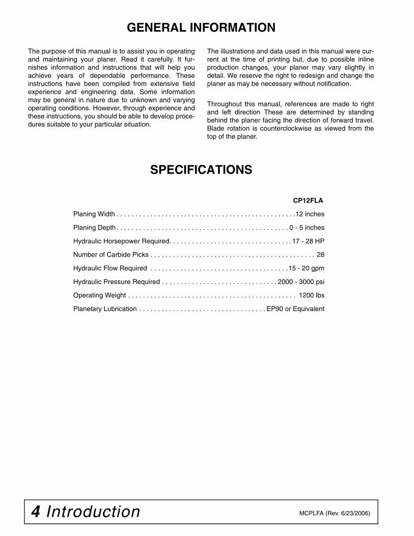
SPECIFICATIONS
CP12FLA
Planing Width . . . . . . . . . . . . . . . . . . . . . . . . . . . . . . . . . . . . . . . . . . . . . . . .12 inches
Planing Depth . . . . . . . . . . . . . . . . . . . . . . . . . . . . . . . . . . . . . . . . . . . . . . 0 - 5 inches
Hydraulic Horsepower Required. . . . . . . . . . . . . . . . . . . . . . . . . . . . . . . . .17 - 28 HP
Number of Carbide Picks . . . . . . . . . . . . . . . . . . . . . . . . . . . . . . . . . . . . . . . . . . . . 28
Hydraulic Flow Required . . . . . . . . . . . . . . . . . . . . . . . . . . . . . . . . . . . . .15 - 20 gpm
Hydraulic Pressure Required . . . . . . . . . . . . . . . . . . . . . . . . . . . . . . . 2000 - 3000 psi
Operating Weight . . . . . . . . . . . . . . . . . . . . . . . . . . . . . . . . . . . . . . . . . . . . . 1200 lbs
Planetary Lubrication . . . . . . . . . . . . . . . . . . . . . . . . . . . . . . . . . . EP90 or Equivalent
The purpose of this manual is to assist you in operatingand maintaining your planer. Read it carefully. It fur-nishes information and instructions that will help youachieve years of dependable performance. Theseinstructions have been compiled from extensive fieldexperience and engineering data. Some informationmay be general in nature due to unknown and varyingoperating conditions. However, through experience andthese instructions, you should be able to develop proce-dures suitable to your particular situation.
The illustrations and data used in this manual were cur-rent at the time of printing but, due to possible inlineproduction changes, your planer may vary slightly indetail. We reserve the right to redesign and change theplaner as may be necessary without notification.
Throughout this manual, references are made to rightand left direction These are determined by standingbehind the planer facing the direction of forward travel.Blade rotation is counterclockwise as viewed from thetop of the planer.

Safety 5Alitec CP (Rev. 7/7/2006)
INSTALLATIONHydraulics must be connected as instructed in
this manual. Do not substitute parts, modify, orconnect in any other way.
After connecting hoses, check that all controllever positions function as instructed in the Opera-tor's Manual. Do not put into service until controllever and equipment movements are correct.
TRAININGSafety instructions are important! Read all
attachment and power unit manuals; follow allsafety rules and safety decal information. (Replace-ment manuals and safety decals are available fromyour dealer. To locate your nearest dealer, checkthe Dealer Locator at www.WoodsEquipment.com,or in the United States and Canada call 1-800-848-3447.) Failure to follow instructions or safety rulescan result in serious injury or death.
If you do not understand any part of this manualand need assistance, see your dealer.
Know your controls and how to stop engine andattachment quickly in an emergency.
Operators must be instructed in and be capableof the safe operation of the equipment, its attach-ments, and all controls. Do not allow anyone tooperate this equipment without proper instruc-tions.
Keep hands and body away from pressurizedlines. Use paper or cardboard, not hands or otherbody parts to check for leaks. Wear safety goggles.Hydraulic fluid under pressure can easily penetrateskin and will cause serious injury or death.
Make sure that all operating and service person-nel know that if hydraulic fluid penetrates skin, it
must be surgically removed as soon as possible bya doctor familiar with this form of injury or gan-grene, serious injury, or death will result. CON-TACT A PHYSICIAN IMMEDIATELY IF FLUIDENTERS SKIN OR EYES. DO NOT DELAY.
Never allow children or untrained persons tooperate equipment.
PREPARATIONCheck that all hardware is properly installed.
Always tighten to torque chart specificationsunless instructed otherwise in this manual.
Counterweight ballast may be required formachine stability. Check your power unit manual orcontact your dealer.
Air in hydraulic systems can cause erratic oper-ation and allows loads or equipment componentsto drop unexpectedly. When connecting equipmentor hoses or performing any hydraulic maintenance,purge any air in hydraulic system by operating allhydraulic functions several times. Do this beforeputt ing into service or al lowing anyone toapproach the equipment.
After connecting hoses, check that all controllever positions function as instructed in the Opera-tor's Manual. Do not put into service until controllever and equipment movements are correct.
Protective hose sleeves must cover all hydrau-lic hoses within 20 inches of the operator and besecured onto metal hose fittings. Replace hoses orsleeves if damaged or if protective sleeve cannotbe properly positioned or secured.
Make sure all hydraulic hoses, fittings, andvalves are in good condition and not leaking beforestarting power unit or using equipment. Check androute hoses carefully to prevent damage. Hosesmust not be twisted, bent sharply, kinked, frayed,pinched, or come into contact with any movingparts. Operate moveable components through fulloperational range to check clearances. Replaceany damaged hoses immediately.
Your dealer can supply original equipmenthydraulic accessories and repair parts. Substituteparts may not meet original equipment specifica-tions and may be dangerous.
Always wear relatively tight and belted clothingto avoid getting caught in moving parts. Wearsturdy, rough-soled work shoes and protectiveequipment for eyes, hair, hands, hearing, and head;and respirator or filter mask where appropriate.
Safety is a primary concern in the design andmanufacture of our products. Unfortunately, ourefforts to provide safe equipment can be wipedout by an operator’s single careless act.
In addition to the design and configuration ofequipment, hazard control and accident preven-tion are dependent upon the awareness, concern,judgement, and proper training of personnelinvolved in the operation, transport, maintenanceand storage of equipment.
It has been said “The best safety device is aninformed, careful operator.” We ask you to be thatkind of operator.
SAFETY RULESATTENTION! BECOME ALERT! YOUR SAFETY IS INVOLVED!

6 Safety Alitec CP (Rev. 7/7/2006)
Be sure attachment is properly secured,adjusted, and in good operating condition. Couplerlockpins must be fully extended and properlyengaged into attachment retaining slots.
Power unit must be equipped with ROPS andseat belt/operator restraint. Keep seat belt/operatorrestraint securely fastened/engaged. Falling offpower unit can result in death from being run overor crushed. Keep ROPS systems in place at alltimes.
Make sure all safety decals are installed.Replace if damaged. (See Safety Decals section forlocation.)
Make sure shields and guards are properlyinstalled and in good condition. Replace if dam-aged.
Inspect and clear area of stones, branches, orother hard objects that might be thrown, causinginjury or damage.
OPERATION
Improper operation can cause the machine to tip or roll over and cause injury or death.
• Keep power unit lift arms and attachment aslow as possible.• Do not travel or turn with power unit lift armsand attachment raised.• Turn only on level ground.• Go up and down slopes, not across them.• Keep the heavy end of the machine uphill.• Do not overload the machine.
Never use attachment to carry loads that exceedthe rated operating capacity or other specificationsof the power unit. Check your power unit manual orsee your dealer for rated operating capacity.Exceeding this capacity can cause machine to tip,roll over, or present other hazards that can causeinjury or death.
Do not allow bystanders in the area when oper-ating, attaching, removing, assembling, or servic-ing equipment.
Contact with high voltage, overhead powerlines, underground cables, gas lines, and otherhazards can cause serious injury or death fromelectrocution, explosion, or fire.
Keep bystanders away from equipment.
Never direct discharge toward people, animals,or property.
Do not operate or transport equipment whileunder the influence of alcohol or drugs.
Operate only in daylight or good artificial light.
Keep hands, feet, hair, and clothing away fromequipment while engine is running. Stay clear of allmoving parts.
Always comply with all state and local lightingand marking requirements.
Do not allow riders. Do not lift or carry anybodyon the power unit or attachments.
Always sit in power unit seat when operatingcontrols or starting engine. Securely fasten seatbelt/operator restraint, place transmission in parkor neutral, engage brake and ensure all other con-trols are disengaged before starting power unitengine.
Look down and to the rear and make sure areais clear before operating in reverse.
Use extreme care when working close to fences,ditches, other obstructions, or on hillsides.
Do not operate or transport on steep slopes.
Do not stop, start, or change directions sud-denly on slopes.
Use extreme care and reduce ground speed onslopes and rough terrain.
Watch for hidden hazards on the terrain duringoperation.
Stop power unit and implement immediatelyupon striking an obstruction. Dismount power unit,using proper procedure. Inspect and repair anydamage before resuming operation.
Leak down or failure of mechanical or hydraulicsystem can cause equipment to drop.
Before making any adjustments on attachment,stop engine and engage parking brake. Neveradjust or work on attachment while the power unitor attachment is running.
Before leaving operator's seat, lower lift armsand put attachment on the ground. Engage brake,stop engine, remove key, and remove seat belt.
MAINTENANCE
Before leaving operator's seat, lower lift armsand put attachment on the ground. Engage brake,stop engine, remove key, and remove seat belt.
NEVER GO UNDERNEATH EQUIPMENT. Neverplace any part of the body underneath equipment
SAFETY RULESATTENTION! BECOME ALERT! YOUR SAFETY IS INVOLVED!

Safety 7Alitec CP (Rev. 7/7/2006)
or between moveable parts even when the enginehas been turned off. Hydraulic system leak-down,hydraulic system failures, mechanical failures, ormovement of control levers can cause equipmentto drop or rotate unexpectedly and cause severeinjury or death.
• Service work does not require going under-neath.• Read Operator's Manual for service instruc-tions or have service performed by a qualifieddealer.
Do not modify or alter or permit anyone else tomodify or alter the equipment or any of its compo-nents in any way.
Your dealer can supply original equipmenthydraulic accessories and repair parts. Substituteparts may not meet original equipment specifica-tions and may be dangerous.
When removing front wheel pins, be sure tosupport the front of the depth skid to preventhands or feet from being crushed.
Always wear relatively tight and belted clothingto avoid getting caught in moving parts. Wearsturdy, rough-soled work shoes and protectiveequipment for eyes, hair, hands, hearing, and head;and respirator or filter mask where appropriate.
Do not allow bystanders in the area when oper-ating, attaching, removing, assembling, or servic-ing equipment.
Be sure attachment is properly secured,adjusted, and in good operating condition. Couplerlockpins must be fully extended and properlyengaged into attachment retaining slots.
Never perform service or maintenance withengine running.
Keep all persons away from operator controlarea while performing adjustments, service, ormaintenance.
Tighten all bolts, nuts, and screws to torquechart specifications. Check that all cotter pins areinstalled securely to ensure equipment is in a safecondition before putting unit into service.
Make sure all safety decals are installed.Replace if damaged. (See Safety Decals section forlocation.)
Make sure shields and guards are properlyinstalled and in good condition. Replace if dam-aged.
Do not disconnect hydraulic lines until all sys-tem pressure is relieved. Lower unit to ground,stop engine, and operate all hydraulic controllevers.
Leak down or failure of mechanical or hydraulicsystem can cause equipment to drop.
STORAGE
Follow manual instructions for storage.
Keep children and bystanders away from stor-age area.
SAFETY RULESATTENTION! BECOME ALERT! YOUR SAFETY IS INVOLVED!

8 Safety MCPLFA (Rev. 6/23/2006)
SAFETY & INSTRUCTIONAL DECALSATTENTION! BECOME ALERT! YOUR SAFETY IS INVOLVED!
Replace Immediately If Damaged!
WARNING
PINCH AREAKeep clear during operation.
D0192
WARNINGFLYING OBJECT
HAZARDKeep clear during
operation.D0195
WARNINGFLYING OBJECT
HAZARDKeep clear during
operation.D0195
(Safety Decals continued on next page)
WARNINGROTATING CUTTER
Keep clear during operation.See Operator's Manualfor maintenance precautions.
D0193
TO AVOID SERIOUS INJURY OR DEATH:Read operator's manual and power unit manual before operating, servicing, or repairing attachment. Follow all safety rules and instructions. (Manuals are available from dealer or, in the United States and Canada, call 1-800-790-0557.)Only operate from operator's seat with seat belt/operator restraint securely fastened.Before leaving operator's seat: follow power unit manual instructions, lower lift arms and attachment to ground, stop engine, remove key, engage brake, and remove seat belt/operator restraint.
Allow no children or untrained persons to operate equipment.
WARNING
D0404-A
6 - D0195
8 - SERIAL NUMBER PLATE 5 - D0193
10 - D0404
12 - 19924 4 - D0192
������������ ���� �� �� ���� ��� ��������� ������� ���� �� ������ ����� �������� �� ������
� Check for leaks with cardboard; never use hand.� Before loosening fittings: lower load, release pressure, and
be sure oil is cool.� Consult physician immediately if skin penetration occurs.
WARNING
19924-B
MODEL NO. SERIAL NO.
Woods Equipment CompanyOregon, Illinois, U.S.A.
Safety 9MCPLFA (Rev. 6/23/2006)
SAFETY & INSTRUCTIONAL DECALSATTENTION! BECOME ALERT! YOUR SAFETY IS INVOLVED!
Replace Immediately If Damaged!
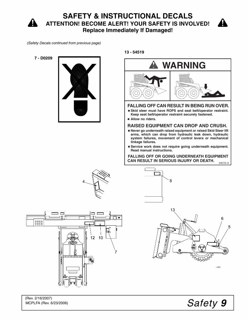
WARNING
FALLING OFF CAN RESULT IN BEING RUN OVER. � Skid steer must have ROPS and seat belt/operator restraint.
Keep seat belt/operator restraint securely fastened.� Allow no riders.
RAISED EQUIPMENT CAN DROP AND CRUSH.� Never go underneath raised equipment or raised Skid Steer lift
arms, which can drop from hydraulic leak down, hydraulicsystem failures, movement of control levers or mechanicallinkage failures.
� Service work does not require going underneath equipment.Read manual instructions.
FALLING OFF OR GOING UNDERNEATH EQUIPMENTCAN RESULT IN SERIOUS INJURY OR DEATH.
54519--A
(Safety Decals continued from previous page)
13 - 545197 - D0209
(Rev. 2/16/2007)
10 Operation MCPLFA (Rev. 6/23/2006)
OPERATION
Safety instructions are important! Read allattachment and power unit manuals; follow allsafety rules and safety decal information. (Replace-ment manuals and safety decals are available fromyour dealer.) Failure to follow instructions or safetyrules can result in serious injury or death.
Power unit must be equipped with ROPS andseat belt/operator restraint. Keep seat belt/operatorrestraint securely fastened/engaged. Falling offpower unit can result in death from being run overor crushed. Keep ROPS systems in place at alltimes.
Operators must be instructed in and be capableof the safe operation of the equipment, its attach-ments, and all controls. Do not allow anyone tooperate this equipment without proper instructions.
NOTICE■ Skid steers must be equipped with an auxiliaryhydraulic system capable of supplying continuousflow for hydraulic motor operation.
PRE-OPERATION CHECK LIST
(OWNER'S RESPONSIBILITY)
___ Review and follow all safety rules and safetydecal instructions on page 5 through page 9.
___ Check that all safety decals are installed and ingood condition. Replace if damaged.
___ Check that all shields and guards are properlyinstalled and in good condition. Replace ifdamaged.
___ Check that equipment is properly and securelyattached to skid steer.
___ Check that all hardware and cotter pins areproperly installed and secured.
___ Do not allow riders. Keep all bystanders awayfrom equipment working area.
___ Check all lubrication points and grease asinstructed. See “Lubrication” on page 22.
___ Check that all hydraulic hoses and fittings arein good condition and not leaking before start-ing skid steer.
___ Check that hoses are not twisted, bent sharply,kinked, frayed or pulled tight. Replace anydamaged hoses immediately.
___ Make sure skid steer ROPS and seat belt arein good condition. Keep seat belt securely fas-tened during operation.
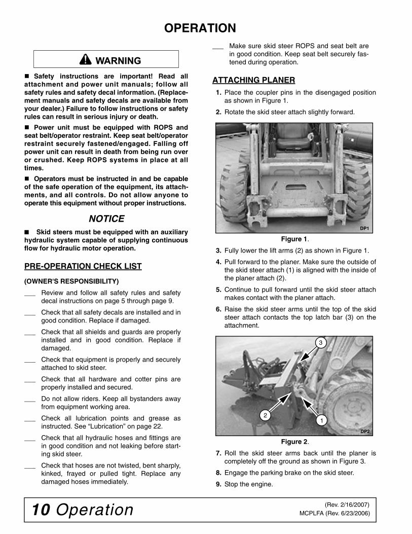
ATTACHING PLANER1. Place the coupler pins in the disengaged position
as shown in Figure 1.
2. Rotate the skid steer attach slightly forward.
Figure 1.
3. Fully lower the lift arms (2) as shown in Figure 1.
4. Pull forward to the planer. Make sure the outside ofthe skid steer attach (1) is aligned with the inside ofthe planer attach (2).
5. Continue to pull forward until the skid steer attachmakes contact with the planer attach.
6. Raise the skid steer arms until the top of the skidsteer attach contacts the top latch bar (3) on theattachment.
Figure 2.
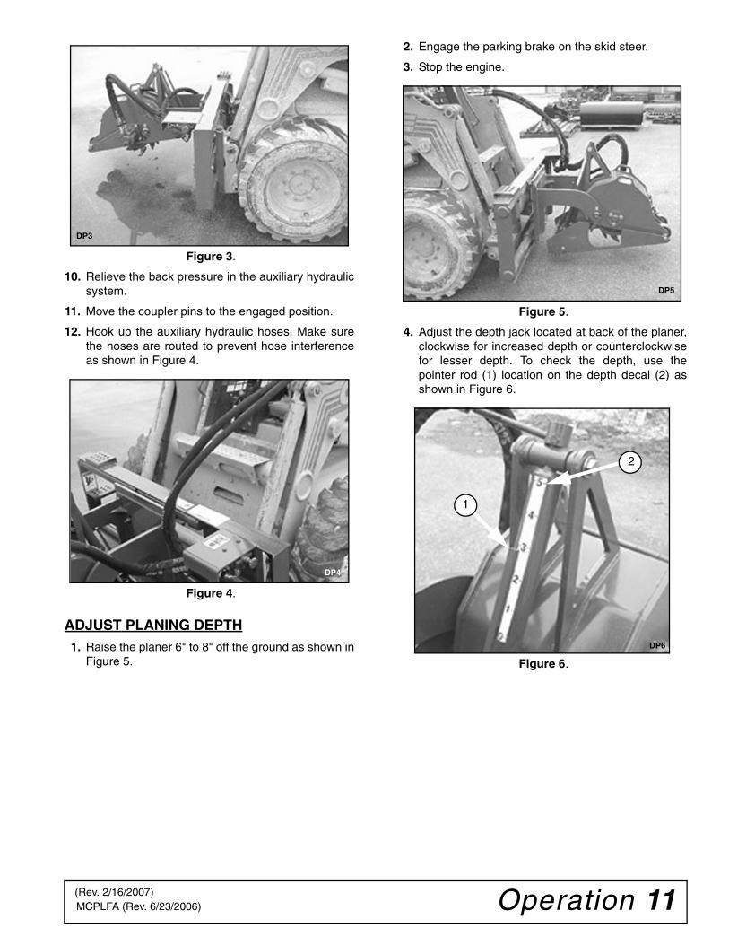
7. Roll the skid steer arms back until the planer iscompletely off the ground as shown in Figure 3.
8. Engage the parking brake on the skid steer.
9. Stop the engine.
WARNING
DP1
DP2
3
21
(Rev. 2/16/2007)
Operation 11MCPLFA (Rev. 6/23/2006)
Figure 3.
10. Relieve the back pressure in the auxiliary hydraulicsystem.
11. Move the coupler pins to the engaged position.
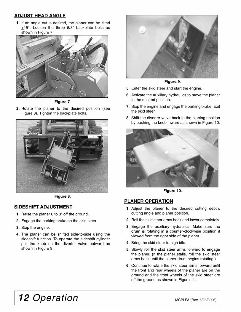
12. Hook up the auxiliary hydraulic hoses. Make surethe hoses are routed to prevent hose interferenceas shown in Figure 4.
Figure 4.
ADJUST PLANING DEPTH1. Raise the planer 6" to 8" off the ground as shown in
Figure 5.
2. Engage the parking brake on the skid steer.
3. Stop the engine.
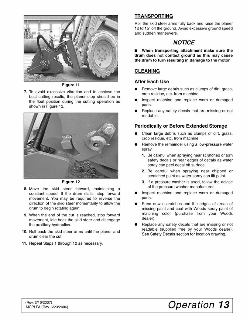
Figure 5.
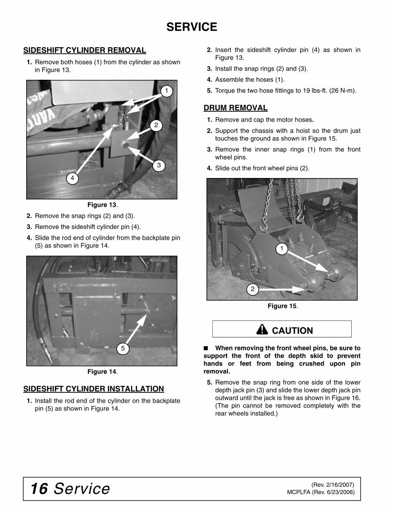
4. Adjust the depth jack located at back of the planer,clockwise for increased depth or counterclockwisefor lesser depth. To check the depth, use thepointer rod (1) location on the depth decal (2) asshown in Figure 6.
Figure 6.
DP3
DP4
DP5
1
2
DP6
(Rev. 2/16/2007)
12 Operation MCPLFA (Rev. 6/23/2006)
ADJUST HEAD ANGLE1. If an angle cut is desired, the planer can be tilted
+15°. Loosen the three 5/8" backplate bolts asshown in Figure 7.
Figure 7.
2. Rotate the planer to the desired position (seeFigure 8). Tighten the backplate bolts.
Figure 8.
SIDESHIFT ADJUSTMENT1. Raise the planer 6 to 8" off the ground.
2. Engage the parking brake on the skid steer.
3. Stop the engine.
4. The planer can be shifted side-to-side using thesideshift function. To operate the sideshift cylinderpull the knob on the diverter valve outward asshown in Figure 9.
Figure 9.
5. Enter the skid steer and start the engine.
6. Activate the auxiliary hydraulics to move the planerto the desired position.
7. Stop the engine and engage the parking brake. Exitthe skid steer.
8. Shift the diverter valve back to the planing positionby pushing the knob inward as shown in Figure 10.
Figure 10.
PLANER OPERATION1. Adjust the planer to the desired cutting depth,
cutting angle and planer position.
2. Roll the skid steer arms back and lower completely.
3. Engage the auxiliary hydraulics. Make sure thedrum is rotating in a counter-clockwise position ifviewed from the right side of the planer.
4. Bring the skid steer to high idle.
5. Slowly roll the skid steer arms forward to engagethe planer. (If the planer stalls, roll the skid steerarms back until the planer drum begins rotating.)
6. Continue to rotate the skid steer arms forward untilthe front and rear wheels of the planer are on theground and the front wheels of the skid steer areoff the ground as shown in Figure 11.
Operation 13MCPLFA (Rev. 6/23/2006)
Figure 11.
7. To avoid excessive vibration and to achieve thebest cutting results, the planer stop should be inthe float position during the cutting operation asshown in Figure 12.
Figure 12.
8. Move the skid steer forward, maintaining aconstant speed. If the drum stalls, stop forwardmovement. You may be required to reverse thedirection of the skid steer momentarily to allow thedrum to begin rotating again.
9. When the end of the cut is reached, stop forwardmovement, idle back the skid steer and disengagethe auxiliary hydraulics.
10. Roll back the skid steer arms until the planer anddrum clear the cut.
11. Repeat Steps 1 through 10 as necessary.
TRANSPORTINGRoll the skid steer arms fully back and raise the planer12 to 15” off the ground. Avoid excessive ground speedand sudden maneuvers.
NOTICE■ When transporting attachment make sure thedrum does not contact ground as this may causethe drum to turn resulting in damage to the motor.
CLEANING
After Each Use● Remove large debris such as clumps of dirt, grass,
crop residue, etc. from machine.
● Inspect machine and replace worn or damagedparts.
● Replace any safety decals that are missing or notreadable.
Periodically or Before Extended Storage● Clean large debris such as clumps of dirt, grass,
crop residue, etc. from machine.
● Remove the remainder using a low-pressure waterspray.
1. Be careful when spraying near scratched or tornsafety decals or near edges of decals as waterspray can peel decal off surface.
2. Be careful when spraying near chipped orscratched paint as water spray can lift paint.
3. If a pressure washer is used, follow the adviceof the pressure washer manufacturer.
● Inspect machine and replace worn or damagedparts.
● Sand down scratches and the edges of areas ofmissing paint and coat with Woods spray paint ofmatching color (purchase from your Woodsdealer).
● Replace any safety decals that are missing or notreadable (supplied free by your Woods dealer).See Safety Decals section for location drawing.
(Rev. 2/16/2007)

14 Troubleshooting MCPLFA (Rev. 6/23/2006)
TROUBLESHOOTING
PROBLEM POSSIBLE CAUSES CHECK THE FOLLOWING
Motor on the planer will not operate
Auxiliary hoses are not hooked up to the skid steer
Inspect the connections visually (make sure the quick couplers are fully engaged).
The diverter valve is in the sideshift position
Make sure the diverter valve knob is pushed all the way in.
There is an obstruction in one or both of the auxiliary hoses
Remove and inspect the hoses visually.
One or more seals on the motor have failed
Contact your dealer.
The skid steer auxiliary hydraulics are not operating properly
Refer to the skid steer owner’s manual.
Drum rotates sluggishly The diverter valve is not fully shifted to the planer position
Make sure diverter valve knob is pushed all the way in.
Insufficient hydraulic flow from the skid steer
Refer to the skid steer owner’s manual.
The hydraulic oil filter on the skid steer is dirty
Refer to the skid steer owner’s manual.
One or more seals on the motor have failed
Contact your dealer.
Motor operates, but the drum does not rotate
Key on the motor is sheared Inspect visually and replace as required.
Oil is leaking from the motor area
One or more seals on the motor have failed
Contact your dealer.
O-rings on fittings are damaged Visually inspect O-rings and replace as needed.
Fittings are loose or damaged Replace or tighten as required.
Hydraulic hoses are loose or damaged Replace or tighten as required.
Insufficient cutting power One or more seals on the motor have failed
Contact your dealer.
Oil filter on the skid steer is dirty Refer to the skid steer owner’s manual.
Insufficient auxiliary flow from the skid steer
Refer to the skid steer owner’s manual.
Relief valve on the skid steer is not set properly
Refer to the skid steer owner’s manual.
Excessive oil temperature
Obstruction in one or both auxiliary hydraulic hoses
Remove and visually inspect and replace the hoses as necessary.
Hydraulic oil level on the skid steer is low
Refer to the skid steer owner’s manual.
Hydraulic oil in the skid steer is dirty Refer to the skid steer owner’s manual.
Hydraulic oil filter on the skid steer is dirty
Refer to the skid steer owner’s manual.
Relief valve on the skid steer is not set properly
Refer to the skid steer owner’s man-ual.

Troubleshooting 15MCPLFA (Rev. 6/23/2006)
Drum rotates in the wrong direction
Auxiliary hydraulics are being activated in the wrong direction
Reverse direction of the auxiliary flow.
Quick disconnects are switched on the auxiliary hoses
Switch male and female auxiliary quick couplers.
Hydraulic sideshift is notoperating
Diverter valve is set in the planer position
Make sure the diverter valve knob ispulled all the way out.
Hoses to the sideshift cylinder areobstructed
Remove and visually inspect andreplace the hoses as necessary.
One or more seals in the sideshift cylinder have failed
Contact your dealer.
Backplate is bound on the sideshiftframe
Remove rod end of the cylinder fromthe backplate and verify that the cylin-der is operating properly (refer to service section).
Insufficient hydraulic flow from the skidsteer
Refer to the skid steer owner’s manual.
Air is trapped in the sideshift cylinderhoses
Take the hoses loose from the cylinder,activate the sideshift function to evacu-ate air and reinstall hoses.
Cylinder rod is bent Visually inspect the cylinder for damage.
Oil leaking from the side-shift cylinder
One or more seals on the cylinder havefailed
Contact your dealer.
O-rings on the fittings are damaged Visually inspect O-rings, replace asrequired.
Fittings loose or damaged Replace or tighten as required.
Hydraulic hoses are loose or damaged Replace or tighten as required.
Excessive vibration during planing operation
Picks are excessively worn Visually inspect the picks. Replace asnecessary.
Insufficient down force due to incorrectoperating procedure
Make sure the chassis stops are in thefloat position during operation. (Referto “Operation” Figure 12 on page 13.)
Pivot pins excessively worn Remove the pins and inspect for wear.
PROBLEM POSSIBLE CAUSES CHECK THE FOLLOWING
16 Service MCPLFA (Rev. 6/23/2006)
SERVICE
SIDESHIFT CYLINDER REMOVAL1. Remove both hoses (1) from the cylinder as shown
in Figure 13.
Figure 13.
2. Remove the snap rings (2) and (3).
3. Remove the sideshift cylinder pin (4).
4. Slide the rod end of cylinder from the backplate pin(5) as shown in Figure 14.
.
Figure 14.
SIDESHIFT CYLINDER INSTALLATION1. Install the rod end of the cylinder on the backplate
pin (5) as shown in Figure 14.
2. Insert the sideshift cylinder pin (4) as shown inFigure 13.
3. Install the snap rings (2) and (3).
4. Assemble the hoses (1).
5. Torque the two hose fittings to 19 lbs-ft. (26 N-m).
DRUM REMOVAL1. Remove and cap the motor hoses.
2. Support the chassis with a hoist so the drum justtouches the ground as shown in Figure 15.
3. Remove the inner snap rings (1) from the frontwheel pins.
4. Slide out the front wheel pins (2).
Figure 15.
■ When removing the front wheel pins, be sure tosupport the front of the depth skid to preventhands or feet from being crushed upon pinremoval.
5. Remove the snap ring from one side of the lowerdepth jack pin (3) and slide the lower depth jack pinoutward until the jack is free as shown in Figure 16.(The pin cannot be removed completely with therear wheels installed.)
4
1
2
3
5
2
1
CAUTION
(Rev. 2/16/2007)
Service 17MCPLFA (Rev. 6/23/2006)
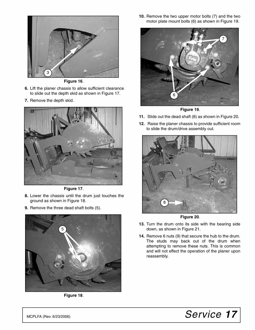
Figure 16.
6. Lift the planer chassis to allow sufficient clearanceto slide out the depth skid as shown in Figure 17.
7. Remove the depth skid.
Figure 17.
8. Lower the chassis until the drum just touches theground as shown in Figure 18.
9. Remove the three dead shaft bolts (5).
Figure 18.
10. Remove the two upper motor bolts (7) and the twomotor plate mount bolts (6) as shown in Figure 19.
Figure 19.
11. Slide out the dead shaft (8) as shown in Figure 20.
12. Raise the planer chassis to provide sufficient roomto slide the drum/drive assembly out.
Figure 20.
13. Turn the drum onto its side with the bearing sidedown, as shown in Figure 21.
14. Remove 6 nuts (9) that secure the hub to the drum.The studs may back out of the drum whenattempting to remove these nuts. This is commonand will not effect the operation of the planer uponreassembly.
3
5
6
7
8
18 Service MCPLFA (Rev. 6/23/2006)
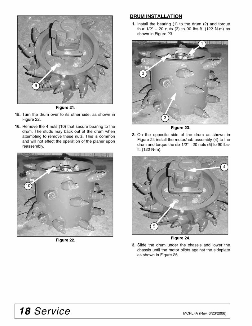
Figure 21.
15. Turn the drum over to its other side, as shown inFigure 22.
16. Remove the 4 nuts (10) that secure bearing to thedrum. The studs may back out of the drum whenattempting to remove these nuts. This is commonand will not effect the operation of the planer uponreassembly.
Figure 22.
DRUM INSTALLATION1. Install the bearing (1) to the drum (2) and torque
four 1/2" – 20 nuts (3) to 90 lbs-ft. (122 N-m) asshown in Figure 23.
Figure 23.
2. On the opposite side of the drum as shown inFigure 24 install the motor/hub assembly (4) to thedrum and torque the six 1/2" – 20 nuts (5) to 90 lbs-ft. (122 N-m).
Figure 24.
3. Slide the drum under the chassis and lower thechassis until the motor pilots against the sideplateas shown in Figure 25.
9
10
3
1
2
5
4
Service 19MCPLFA (Rev. 6/23/2006)
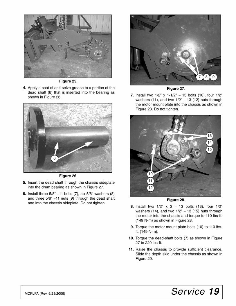
Figure 25.
4. Apply a coat of anti-seize grease to a portion of thedead shaft (6) that is inserted into the bearing asshown in Figure 26.
Figure 26.
5. Insert the dead shaft through the chassis sideplateinto the drum bearing as shown in Figure 27.
6. Install three 5/8" –11 bolts (7), six 5/8" washers (8)and three 5/8" –11 nuts (9) through the dead shaftand into the chassis sideplate. Do not tighten.
Figure 27.
7. Install two 1/2" x 1-1/2" – 13 bolts (10), four 1/2"washers (11), and two 1/2" – 13 (12) nuts throughthe motor mount plate into the chassis as shown inFigure 28. Do not tighten.
Figure 28.
8. Install two 1/2" x 2 – 13 bolts (13), four 1/2"washers (14), and two 1/2" – 13 (15) nuts throughthe motor into the chassis and torque to 110 lbs-ft.(149 N-m) as shown in Figure 28.
9. Torque the motor mount plate bolts (10) to 110 lbs-ft. (149 N-m).
10. Torque the dead-shaft bolts (7) as shown in Figure27 to 220 lbs-ft.
11. Raise the chassis to provide sufficient clearance.Slide the depth skid under the chassis as shown inFigure 29.
6
7 9 8
12
11
15
14
13
10
20 Service MCPLFA (Rev. 6/23/2006)
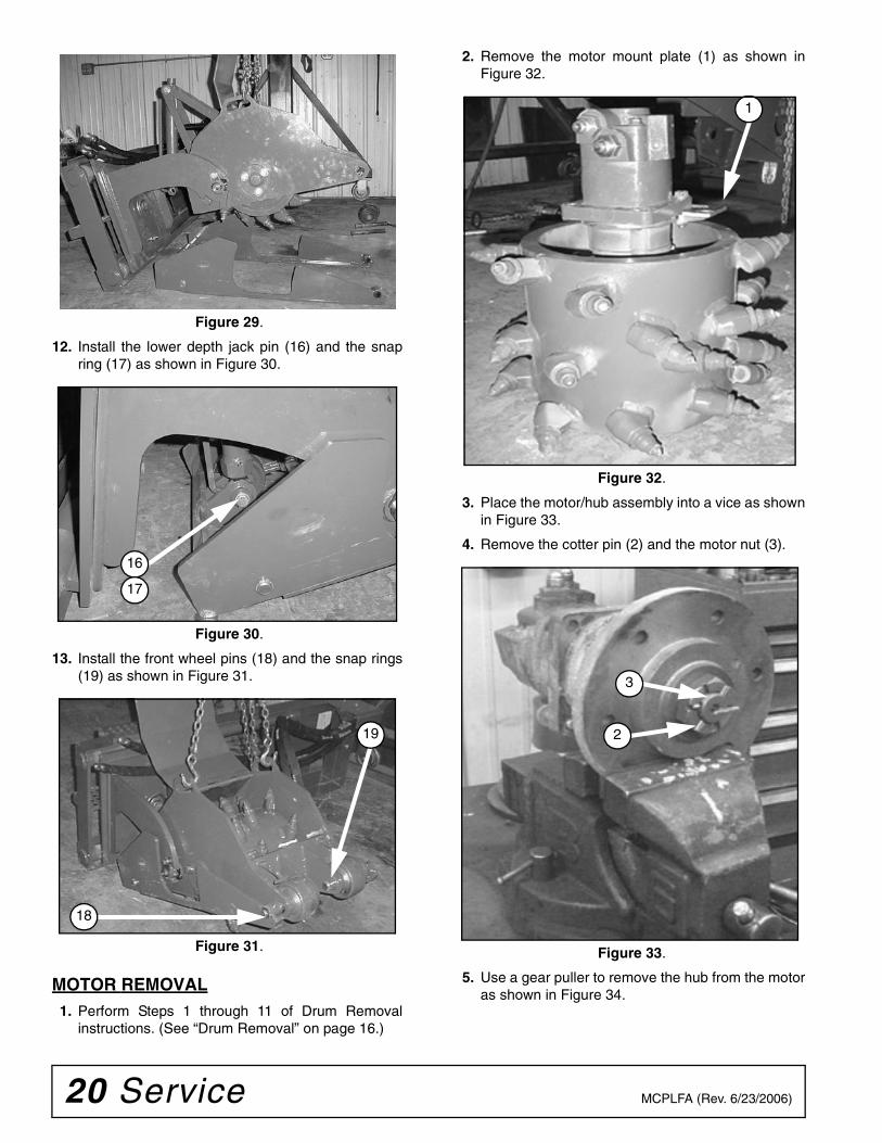
Figure 29.
12. Install the lower depth jack pin (16) and the snapring (17) as shown in Figure 30.
Figure 30.
13. Install the front wheel pins (18) and the snap rings(19) as shown in Figure 31.
.
Figure 31.
MOTOR REMOVAL1. Perform Steps 1 through 11 of Drum Removal
instructions. (See “Drum Removal” on page 16.)
2. Remove the motor mount plate (1) as shown inFigure 32.
Figure 32.
3. Place the motor/hub assembly into a vice as shownin Figure 33.
4. Remove the cotter pin (2) and the motor nut (3).
Figure 33.
5. Use a gear puller to remove the hub from the motoras shown in Figure 34.
16
17
18
19
1
2
3
Service 21MCPLFA (Rev. 6/23/2006)
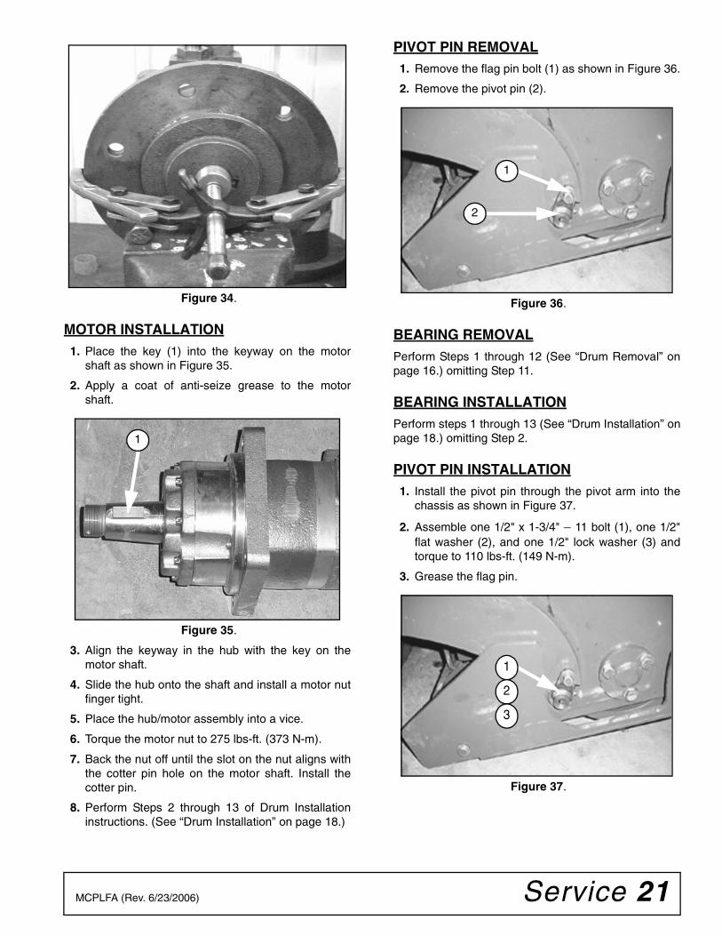
Figure 34.
MOTOR INSTALLATION1. Place the key (1) into the keyway on the motor
shaft as shown in Figure 35.
2. Apply a coat of anti-seize grease to the motorshaft.
Figure 35.
3. Align the keyway in the hub with the key on themotor shaft.
4. Slide the hub onto the shaft and install a motor nutfinger tight.
5. Place the hub/motor assembly into a vice.
6. Torque the motor nut to 275 lbs-ft. (373 N-m).
7. Back the nut off until the slot on the nut aligns withthe cotter pin hole on the motor shaft. Install thecotter pin.
8. Perform Steps 2 through 13 of Drum Installationinstructions. (See “Drum Installation” on page 18.)
PIVOT PIN REMOVAL1. Remove the flag pin bolt (1) as shown in Figure 36.
2. Remove the pivot pin (2).
Figure 36.
BEARING REMOVALPerform Steps 1 through 12 (See “Drum Removal” onpage 16.) omitting Step 11.
BEARING INSTALLATIONPerform steps 1 through 13 (See “Drum Installation” onpage 18.) omitting Step 2.
PIVOT PIN INSTALLATION1. Install the pivot pin through the pivot arm into the
chassis as shown in Figure 37.
2. Assemble one 1/2" x 1-3/4" – 11 bolt (1), one 1/2"flat washer (2), and one 1/2" lock washer (3) andtorque to 110 lbs-ft. (149 N-m).
3. Grease the flag pin.
Figure 37.
1
1
2
1
2
3
22 Service MCPLFA (Rev. 6/23/2006)
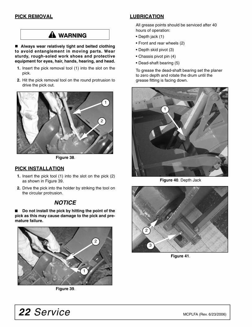
PICK REMOVAL
Always wear relatively tight and belted clothingto avoid entanglement in moving parts. Wearsturdy, rough-soled work shoes and protectiveequipment for eyes, hair, hands, hearing, and head.
1. Insert the pick removal tool (1) into the slot on thepick.
2. Hit the pick removal tool on the round protrusion todrive the pick out.
Figure 38.
PICK INSTALLATION1. Insert the pick tool (1) into the slot on the pick (2)
as shown in Figure 39.
2. Drive the pick into the holder by striking the tool onthe circular protrusion.
NOTICE■ Do not install the pick by hitting the point of thepick as this may cause damage to the pick and pre-mature failure.
Figure 39.
LUBRICATION
All grease points should be serviced after 40 hours of operation:
• Depth jack (1)
• Front and rear wheels (2)
• Depth skid pivot (3)
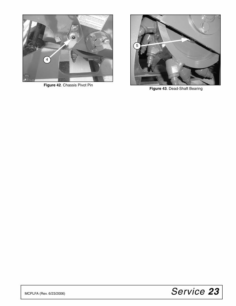
• Chassis pivot pin (4)
• Dead-shaft bearing (5)
To grease the dead-shaft bearing set the planer to zero depth and rotate the drum until the grease fitting is facing down.
Figure 40. Depth Jack
Figure 41.
�������
2
1
2
1
1
2
3
Service 23MCPLFA (Rev. 6/23/2006)
Figure 42. Chassis Pivot Pin Figure 43. Dead-Shaft Bearing
4
5

24 Parts MCPLFA (Rev. 6/23/2006)
CP12FLA
CP12FLA ASSEMBLY........................................................................................................25
CP12FLA ASSEMBLY - NEW HOLLAND ..........................................................................26
BASE ASSEMBLY ..............................................................................................................27
CHASSIS ASSEMBLY........................................................................................................28
DRUM ASSEMBLY.............................................................................................................29
VALVE ASSEMBLY.............................................................................................................29
DRUM / DRIVE ASSEMBLY...............................................................................................30
HYDRAULIC ASSEMBLY...................................................................................................31
HYDRAULIC ASSEMBLY - NEW HOLLAND .....................................................................32
DECAL PLACEMENT.........................................................................................................33
DECAL PLACEMENT - NEW HOLLAND ...........................................................................34
PARTS INDEX
Parts 25MCPLFA (Rev. 6/23/2006)
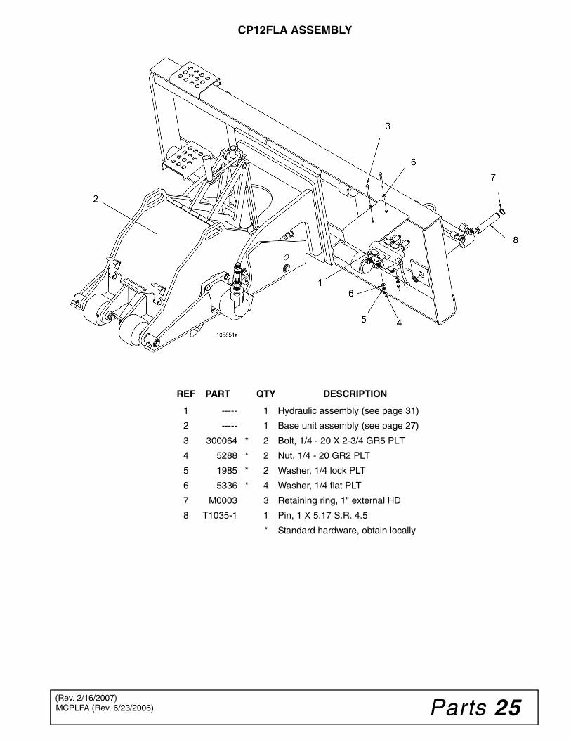
CP12FLA ASSEMBLY
REF PART QTY DESCRIPTION
1 ----- 1 Hydraulic assembly (see page 31)
2 ----- 1 Base unit assembly (see page 27)
3 300064 * 2 Bolt, 1/4 - 20 X 2-3/4 GR5 PLT
4 5288 * 2 Nut, 1/4 - 20 GR2 PLT
5 1985 * 2 Washer, 1/4 lock PLT
6 5336 * 4 Washer, 1/4 flat PLT
7 M0003 3 Retaining ring, 1" external HD
8 T1035-1 1 Pin, 1 X 5.17 S.R. 4.5
* Standard hardware, obtain locally
(Rev. 2/16/2007)
26 Parts MCPLFA (Rev. 6/23/2006)
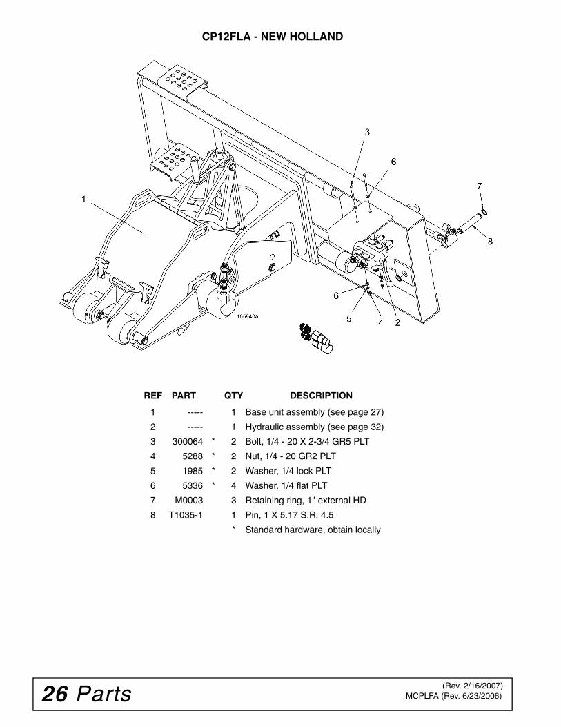
CP12FLA - NEW HOLLAND
REF PART QTY DESCRIPTION
1 ----- 1 Base unit assembly (see page 27)
2 ----- 1 Hydraulic assembly (see page 32)
3 300064 * 2 Bolt, 1/4 - 20 X 2-3/4 GR5 PLT
4 5288 * 2 Nut, 1/4 - 20 GR2 PLT
5 1985 * 2 Washer, 1/4 lock PLT
6 5336 * 4 Washer, 1/4 flat PLT
7 M0003 3 Retaining ring, 1" external HD
8 T1035-1 1 Pin, 1 X 5.17 S.R. 4.5
* Standard hardware, obtain locally
(Rev. 2/16/2007)
Parts 27MCPLFA (Rev. 6/23/2006)
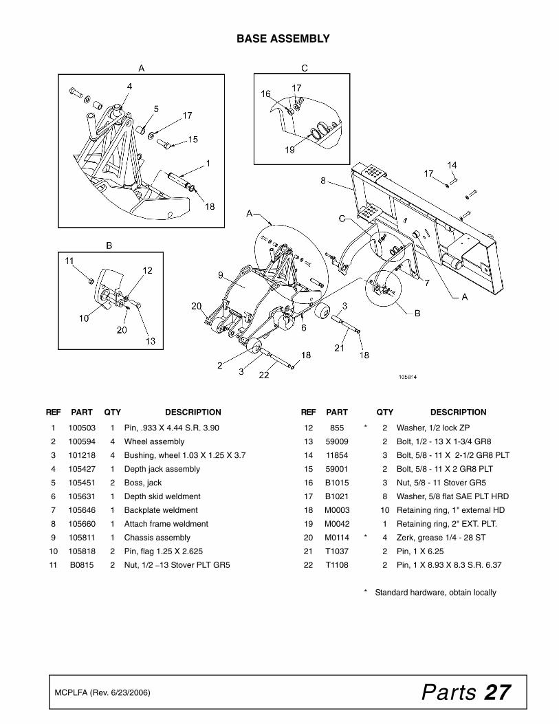
BASE ASSEMBLY
REF PART QTY DESCRIPTION
1 100503 1 Pin, .933 X 4.44 S.R. 3.90
2 100594 4 Wheel assembly
3 101218 4 Bushing, wheel 1.03 X 1.25 X 3.7
4 105427 1 Depth jack assembly
5 105451 2 Boss, jack
6 105631 1 Depth skid weldment
7 105646 1 Backplate weldment
8 105660 1 Attach frame weldment
9 105811 1 Chassis assembly
10 105818 2 Pin, flag 1.25 X 2.625
11 B0815 2 Nut, 1/2 –13 Stover PLT GR5
REF PART QTY DESCRIPTION
12 855 * 2 Washer, 1/2 lock ZP
13 59009 2 Bolt, 1/2 - 13 X 1-3/4 GR8
14 11854 3 Bolt, 5/8 - 11 X 2-1/2 GR8 PLT
15 59001 2 Bolt, 5/8 - 11 X 2 GR8 PLT
16 B1015 3 Nut, 5/8 - 11 Stover GR5
17 B1021 8 Washer, 5/8 flat SAE PLT HRD
18 M0003 10 Retaining ring, 1" external HD
19 M0042 1 Retaining ring, 2" EXT. PLT.
20 M0114 * 4 Zerk, grease 1/4 - 28 ST
21 T1037 2 Pin, 1 X 6.25
22 T1108 2 Pin, 1 X 8.93 X 8.3 S.R. 6.37
* Standard hardware, obtain locally
28 Parts MCPLFA (Rev. 6/23/2006)
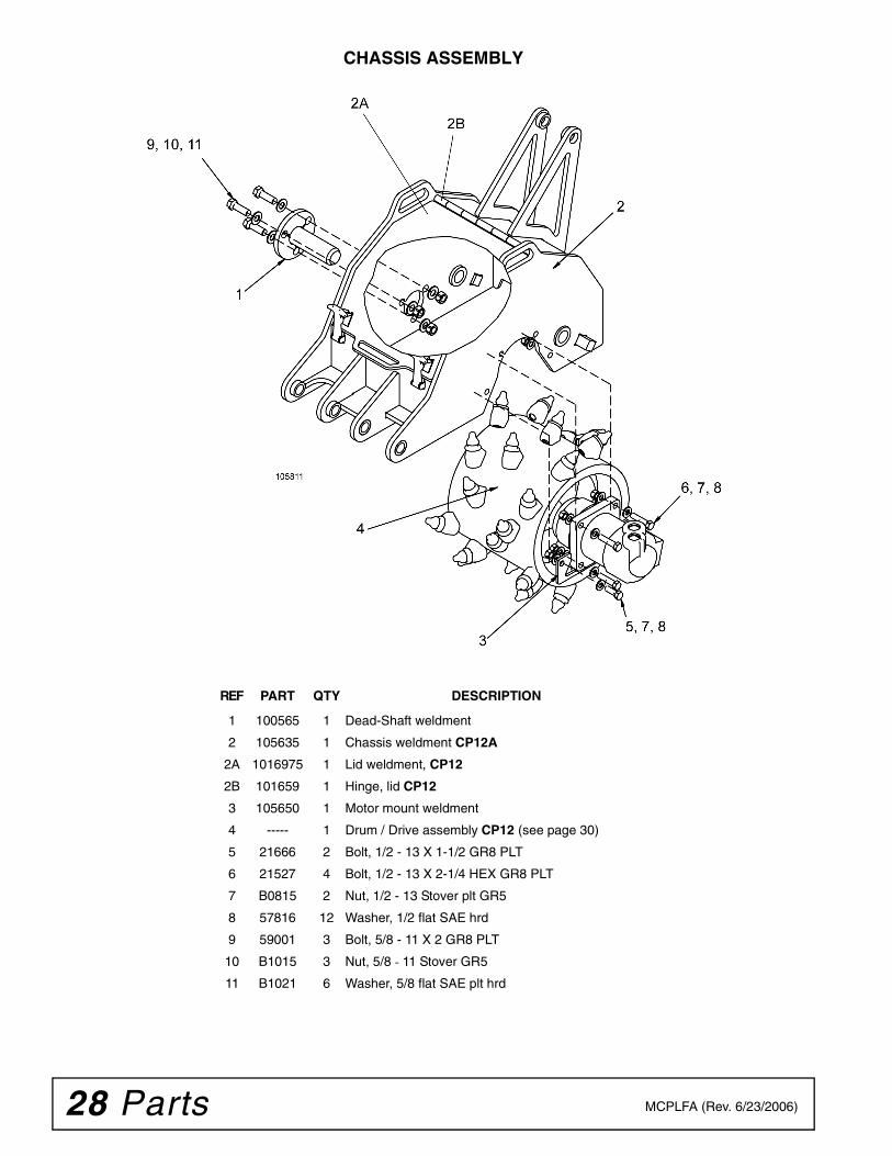
CHASSIS ASSEMBLY
REF PART QTY DESCRIPTION
1 100565 1 Dead-Shaft weldment
2 105635 1 Chassis weldment CP12A
2A 1016975 1 Lid weldment, CP12
2B 101659 1 Hinge, lid CP12
3 105650 1 Motor mount weldment
4 ----- 1 Drum / Drive assembly CP12 (see page 30)
5 21666 2 Bolt, 1/2 - 13 X 1-1/2 GR8 PLT
6 21527 4 Bolt, 1/2 - 13 X 2-1/4 HEX GR8 PLT
7 B0815 2 Nut, 1/2 - 13 Stover plt GR5
8 57816 12 Washer, 1/2 flat SAE hrd
9 59001 3 Bolt, 5/8 - 11 X 2 GR8 PLT
10 B1015 3 Nut, 5/8 - 11 Stover GR5
11 B1021 6 Washer, 5/8 flat SAE plt hrd
Parts 29MCPLFA (Rev. 6/23/2006)
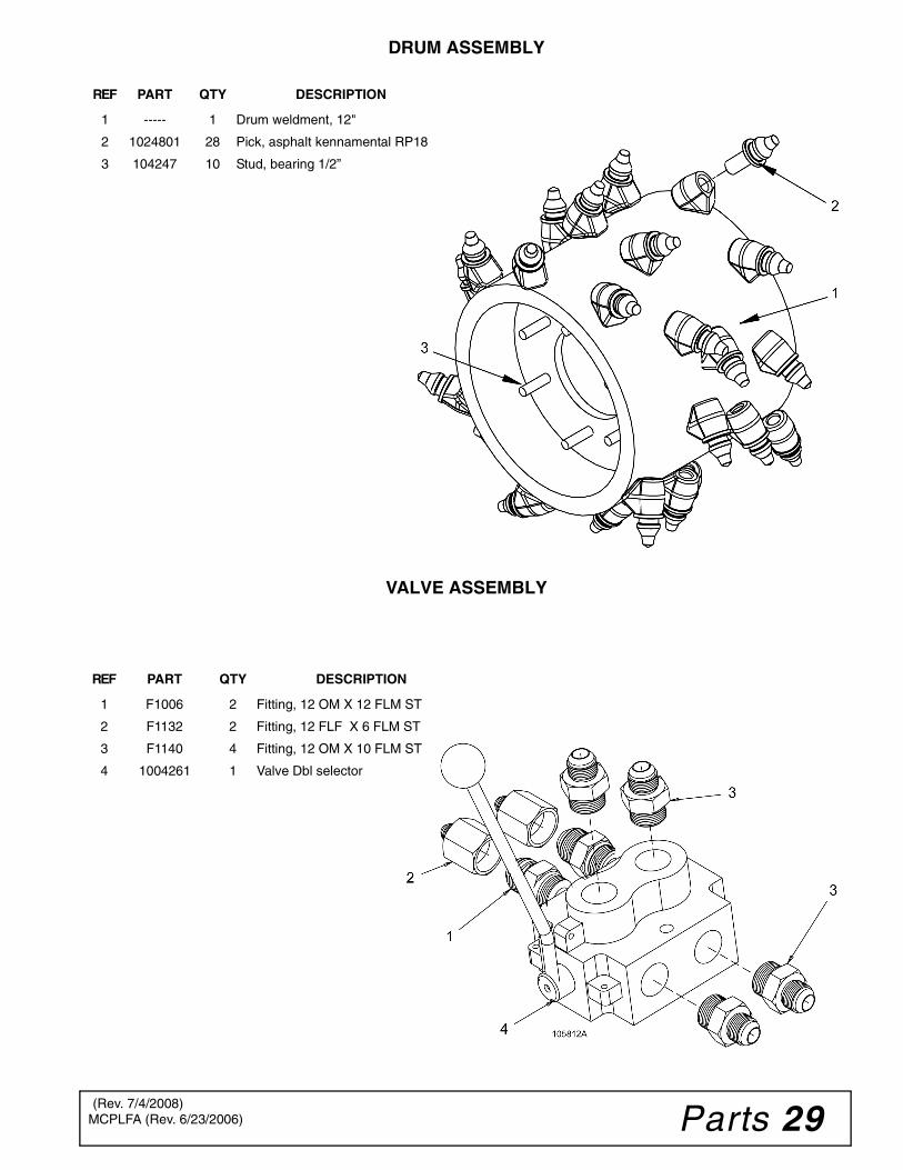
DRUM ASSEMBLY
VALVE ASSEMBLY
REF PART QTY DESCRIPTION
1 ----- 1 Drum weldment, 12"
2 1024801 28 Pick, asphalt kennamental RP18
3 104247 10 Stud, bearing 1/2”
REF PART QTY DESCRIPTION
1 F1006 2 Fitting, 12 OM X 12 FLM ST
2 F1132 2 Fitting, 12 FLF X 6 FLM ST
3 F1140 4 Fitting, 12 OM X 10 FLM ST
4 1004261 1 Valve Dbl selector
(Rev. 7/4/2008)
30 Parts MCPLFA (Rev. 6/23/2006)
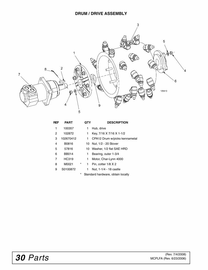
DRUM / DRIVE ASSEMBLY
REF PART QTY DESCRIPTION
1 100357 1 Hub, drive
2 102872 1 Key, 7/16 X 7/16 X 1-1/2
3 102670412 1 CPA12 Drum w/picks kennametal
4 B0816 10 Nut, 1/2 - 20 Stover
5 57816 10 Washer, 1/2 flat SAE HRD
6 BB014 1 Bearing, outer 1-3/4
7 HC319 1 Motor, Char-Lynn 4000
8 M0021 * 1 Pin, cotter 1/8 X 2
9 S0100872 1 Nut, 1-1/4 - 18 castle
* Standard hardware, obtain locally
(Rev. 7/4/2008)
Parts 31MCPLFA (Rev. 6/23/2006)
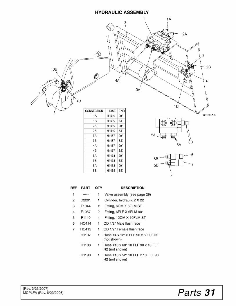
HYDRAULIC ASSEMBLY
REF PART QTY DESCRIPTION
1 ----- 1 Valve assembly (see page 29)
2 C2201 1 Cylinder, hydraulic 2 X 22
3 F1044 2 Fitting, 6OM X 6FLM ST
4 F1057 2 Fitting, 6FLF X 6FLM 90°
5 F1140 4 Fitting, 12OM X 10FLM ST
6 HC414 1 QD 1/2" Male flush face
7 HC415 1 QD 1/2" Female flush face
H1137 1 Hose #4 x 12" 6 FLF 90 x 6 FLF R2 (not shown)
H1188 1 Hose #10 x 60" 10 FLF 90 x 10 FLF R2 (not shown)
H1190 1 Hose #10 x 52" 10 FLF x 10 FLF 90 R2 (not shown)
(Rev. 3/23/2007)
32 Parts MCPLFA (Rev. 6/23/2006)
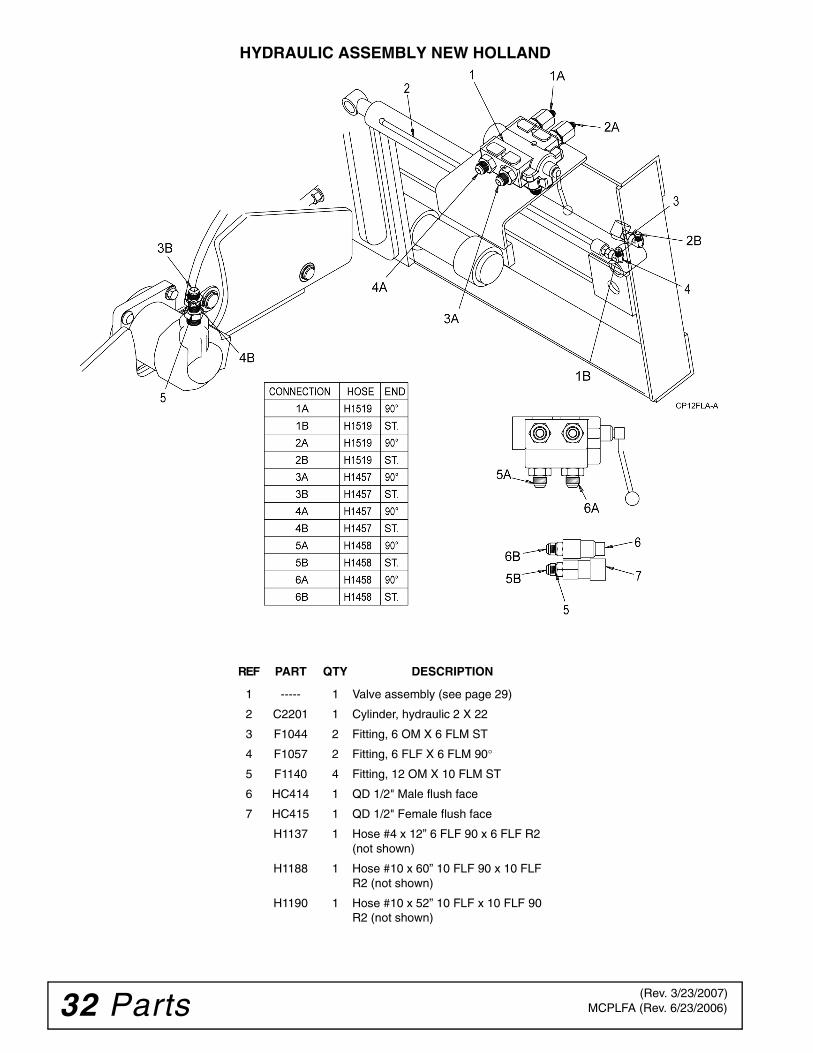
HYDRAULIC ASSEMBLY NEW HOLLAND
REF PART QTY DESCRIPTION
1 ----- 1 Valve assembly (see page 29)
2 C2201 1 Cylinder, hydraulic 2 X 22
3 F1044 2 Fitting, 6 OM X 6 FLM ST
4 F1057 2 Fitting, 6 FLF X 6 FLM 90°
5 F1140 4 Fitting, 12 OM X 10 FLM ST
6 HC414 1 QD 1/2" Male flush face
7 HC415 1 QD 1/2" Female flush face
H1137 1 Hose #4 x 12” 6 FLF 90 x 6 FLF R2 (not shown)
H1188 1 Hose #10 x 60” 10 FLF 90 x 10 FLF R2 (not shown)
H1190 1 Hose #10 x 52” 10 FLF x 10 FLF 90 R2 (not shown)
(Rev. 3/23/2007)
Parts 33MCPLFA (Rev. 6/23/2006)
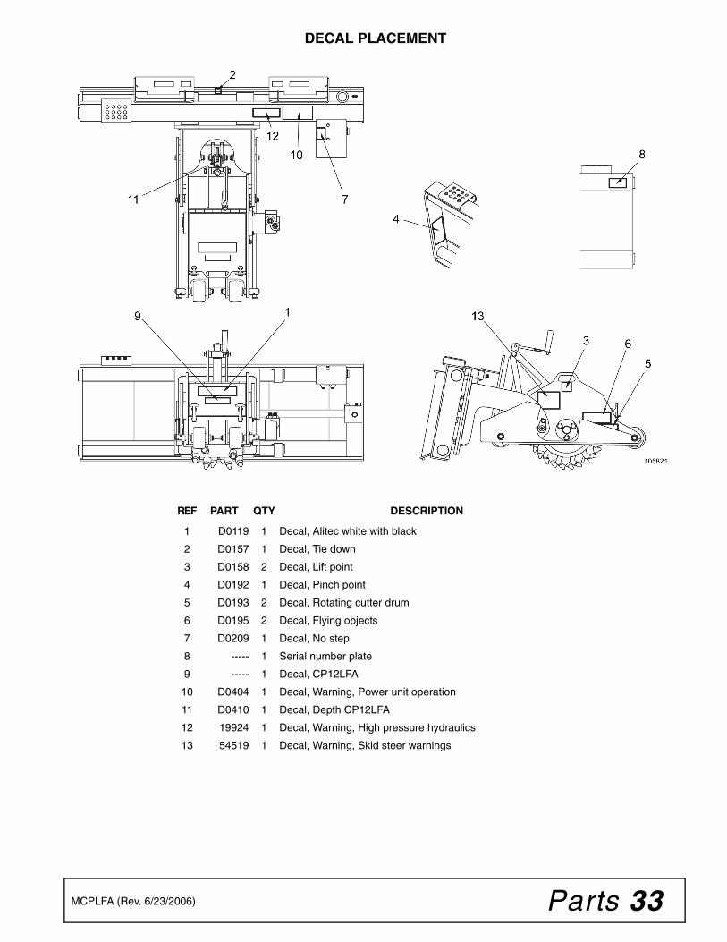
DECAL PLACEMENT
REF PART QTY DESCRIPTION
1 D0119 1 Decal, Alitec white with black
2 D0157 1 Decal, Tie down
3 D0158 2 Decal, Lift point
4 D0192 1 Decal, Pinch point
5 D0193 2 Decal, Rotating cutter drum
6 D0195 2 Decal, Flying objects
7 D0209 1 Decal, No step
8 ----- 1 Serial number plate
9 ----- 1 Decal, CP12LFA
10 D0404 1 Decal, Warning, Power unit operation
11 D0410 1 Decal, Depth CP12LFA
12 19924 1 Decal, Warning, High pressure hydraulics
13 54519 1 Decal, Warning, Skid steer warnings
34 Parts MCPLFA (Rev. 6/23/2006)
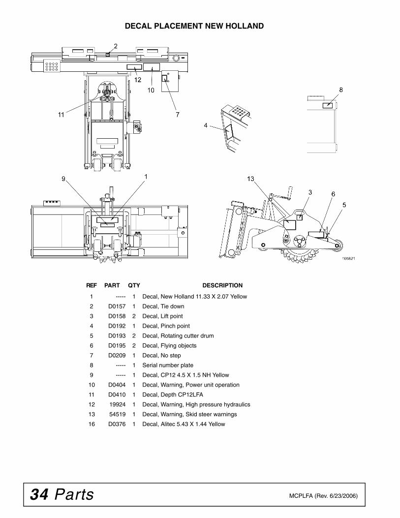
DECAL PLACEMENT NEW HOLLAND
REF PART QTY DESCRIPTION
1 ----- 1 Decal, New Holland 11.33 X 2.07 Yellow
2 D0157 1 Decal, Tie down
3 D0158 2 Decal, Lift point
4 D0192 1 Decal, Pinch point
5 D0193 2 Decal, Rotating cutter drum
6 D0195 2 Decal, Flying objects
7 D0209 1 Decal, No step
8 ----- 1 Serial number plate
9 ----- 1 Decal, CP12 4.5 X 1.5 NH Yellow
10 D0404 1 Decal, Warning, Power unit operation
11 D0410 1 Decal, Depth CP12LFA
12 19924 1 Decal, Warning, High pressure hydraulics
13 54519 1 Decal, Warning, Skid steer warnings
16 D0376 1 Decal, Alitec 5.43 X 1.44 Yellow
Appendix 35MCPLFA (Rev. 6/23/2006)
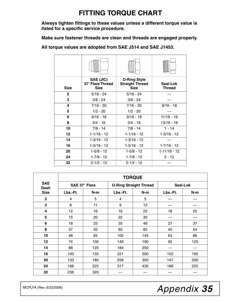
FITTING TORQUE CHARTAlways tighten fittings to these values unless a different torque value is listed for a specific service procedure.
Make sure fastener threads are clean and threads are engaged properly.
All torque values are adopted from SAE J514 and SAE J1453.
Size
SAE (JIC) 37° Flare Thread
Size
O-Ring Style Straight Thread
SizeSeal-LokThread
2 5/16 - 24 5/16 - 24 ---
3 3/8 - 24 3/8 - 24 ---
4 7/16 - 20 7/16 - 20 9/16 - 18
5 1/2 - 20 1/2 - 20 ---
6 9/16 - 18 9/16 - 18 11/16 - 16
8 3/4 - 16 3/4 - 16 13/16 - 16
10 7/8 - 14 7/8 - 14 1 - 14
12 1-1/16 - 12 1-1/16 - 12 1-3/16 - 12
14 1-3/16 - 12 1-3/16 - 12 ---
16 1-5/16 - 12 1-5/16 - 12 1-7/16 - 12
20 1-5/8 - 12 1-5/8 - 12 1-11/16 - 12
24 1-7/8 - 12 1-7/8 - 12 2 - 12
32 2-1/2 - 12 2-1/2 - 12 ---
SAEDashSize
TORQUE
SAE 37° Flare O-Ring Straight Thread Seal-Lok
Lbs.-Ft. N-m Lbs.-Ft. N-m Lbs.-Ft. N-m
2 4 5 4 5 --- ---
3 8 11 9 12 --- ---
4 12 16 16 22 18 25
5 15 20 22 30 --- ---
6 18 25 35 48 27 37
8 37 50 60 82 40 54
10 48 65 105 143 63 86
12 74 100 140 190 92 125
14 88 120 184 250 --- ---
16 100 135 221 300 122 165
20 133 180 258 350 147 200
24 166 225 317 430 166 225
32 236 320 --- --- --- ---
36 Quick Coupler Quick Coupler Chart (Rev. 10/20/2006)
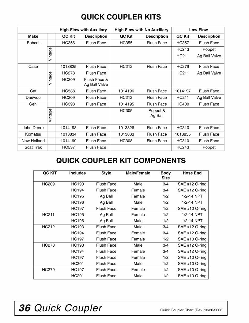
QUICK COUPLER KITS
QUICK COUPLER KIT COMPONENTS
High-Flow with Auxiliary High-Flow with No Auxiliary Low-Flow
Make QC Kit Description QC Kit Description QC Kit Description
Bobcat HC356 Flush Face HC355 Flush Face HC357 Flush Face
Vin
tage HC243 Poppet
HC211 Ag Ball Valve
Case 1013825 Flush Face HC212 Flush Face HC279 Flush Face
Vin
tage HC278 Flush Face HC211 Ag Ball Valve
HC209 Flush Face & Ag Ball Valve
Cat HC538 Flush Face 1014196 Flush Face 1014197 Flush Face
Daewoo HC209 Flush Face HC212 Flush Face HC211 Ag Ball Valve
Gehl HC398 Flush Face 1014195 Flush Face HC400 Flush Face
Vin
tage HC305 Poppet &
Ag Ball
John Deere 1014198 Flush Face 1013826 Flush Face HC310 Flush Face
Komatsu 1013834 Flush Face 1013833 Flush Face 1013835 Flush Face
New Holland 1014199 Flush Face HC308 Flush Face HC310 Flush Face
Scat Trak HC537 Flush Face HC243 Poppet
QC KIT Includes Style Male/Female BodySize
Hose End
HC209 HC193 Flush Face Male 3/4 SAE #12 O-ring
HC194 Flush Face Female 3/4 SAE #12 O-ring
HC195 Ag Ball Female 1/2 1/2-14 NPT
HC196 Ag Ball Male 1/2 1/2-14 NPT
HC197 Flush Face Female 1/2 SAE #10 O-ring
HC211 HC195 Ag Ball Female 1/2 1/2-14 NPT
HC196 Ag Ball Male 1/2 1/2-14 NPT
HC212 HC193 Flush Face Male 3/4 SAE #12 O-ring
HC194 Flush Face Female 3/4 SAE #12 O-ring
HC197 Flush Face Female 1/2 SAE #10 O-ring
HC278 HC193 Flush Face Male 3/4 SAE #12 O-ring
HC194 Flush Face Female 3/4 SAE #12 O-ring
HC197 Flush Face Female 1/2 SAE #10 O-ring
HC201 Flush Face Male 1/2 SAE #10 O-ring
HC279 HC197 Flush Face Female 1/2 SAE #10 O-ring
HC201 Flush Face Male 1/2 SAE #10 O-ring

Quick Coupler 37Quick Coupler Chart (Rev. 10/20/2006)
QUICK COUPLER KIT COMPONENTSQC KIT Includes Style Male/Female Body
SizeHose End
HC308 HC416 Flush Face Female 5/8 SAE #12 O-ring
HC417 Flush Face Male 5/8 SAE #12 O-ring
HC418 Flush Face Male 3/8 SAE #8 O-ring
HC310 HC414 Flush Face Male 1/2 SAE #12 O-ring
HC415 Flush Face Female 1/2 SAE #12 O-ring
HC355 HC344 Flush Face Male 12 mm SAE #12 O-ring
HC345 Flush Face Female 12 mm SAE #12 O-ring
HC346 Flush Face Female 9 mm SAE #8 O-ring
HC356 HC342 Flush Face Female 7 mm SAE #6 O-ring
HC343 Flush Face Male 7 mm SAE #6 O-ring
HC344 Flush Face Male 12 mm SAE #12 O-ring
HC345 Flush Face Female 12 mm SAE #12 O-ring
HC346 Flush Face Female 9 mm SAE #8 O-ring
HC357 HC344 Flush Face Male 12 mm SAE #12 O-ring
HC345 Flush Face Female 12 mm SAE #12 O-ring
HC398 HC344 Flush Face Male 12 mm SAE #12 O-ring
HC345 Flush Face Female 12 mm SAE #12 O-ring
HC346 Flush Face Female 9 mm SAE #8 O-ring
HC400 HC344 Flush Face Male 12 mm SAE #12 O-ring
HC345 Flush Face Female 12 mm SAE #12 O-ring
HC537 HC415 Flush Face Female 1/2 SAE #12 O-ring
HC416 Flush Face Female 5/8 SAE #12 O-ring
HC417 Flush Face Male 5/8 SAE #12 O-ring
HC418 Flush Face Male 3/8 SAE #8 O-ring
HC538 HC521 Flush Face Female 16 mm SAE #12 O-ring
HC522 Flush Face Male 16 mm SAE #12 O-ring
1532994 Flush Face Female 3/4 SAE #12 O-ring
1532995 Flush Face Male 3/4 SAE #12 O-ring
1532997 Flush Face Female 1/2 SAE #8 O-ring
1013825 HC417 Flush Face Male 5/8 SAE #12 O-ring
HC418 Flush Face Male 3/8 SAE #8 O-ring
HC545 Flush Face Female 5/8 SAE #12 O-ring
HC546 Flush Face Female 1/2 SAE #10 O-ring
HC547 Flush Face Male 1/2 SAE #10 O-ring
1013826 HC343 Flush Face Male 7 mm SAE #6 O-ring
HC521 Flush Face Female 16 mm SAE #12 O-ring
HC522 Flush Face Male 16 mm SAE #12 O-ring
1013833 HC415 Flush Face Female 1/2 SAE #12 O-ring
HC521 Flush Face Female 16 mm SAE #12 O-ring
HC522 Flush Face Male 16 mm SAE #12 O-ring
38 Quick Coupler Quick Coupler Chart (Rev. 10/20/2006)
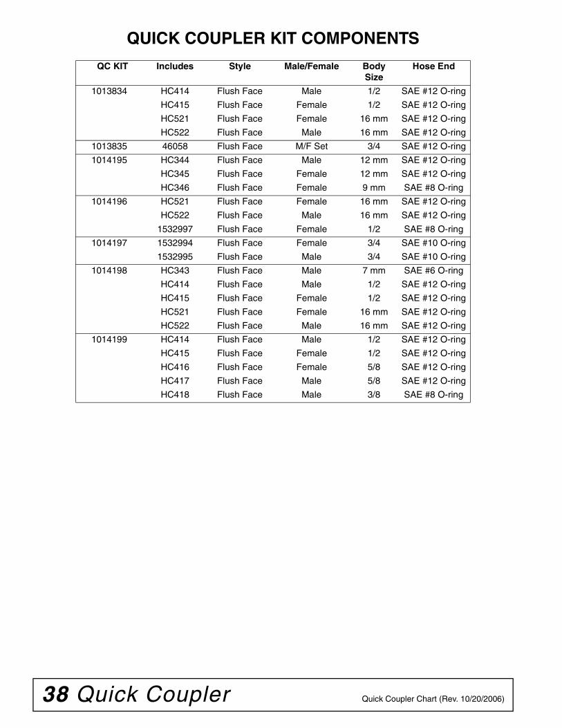
QUICK COUPLER KIT COMPONENTS
QC KIT Includes Style Male/Female BodySize
Hose End
1013834 HC414 Flush Face Male 1/2 SAE #12 O-ring
HC415 Flush Face Female 1/2 SAE #12 O-ring
HC521 Flush Face Female 16 mm SAE #12 O-ring
HC522 Flush Face Male 16 mm SAE #12 O-ring
1013835 46058 Flush Face M/F Set 3/4 SAE #12 O-ring
1014195 HC344 Flush Face Male 12 mm SAE #12 O-ring
HC345 Flush Face Female 12 mm SAE #12 O-ring
HC346 Flush Face Female 9 mm SAE #8 O-ring
1014196 HC521 Flush Face Female 16 mm SAE #12 O-ring
HC522 Flush Face Male 16 mm SAE #12 O-ring
1532997 Flush Face Female 1/2 SAE #8 O-ring
1014197 1532994 Flush Face Female 3/4 SAE #10 O-ring
1532995 Flush Face Male 3/4 SAE #10 O-ring
1014198 HC343 Flush Face Male 7 mm SAE #6 O-ring
HC414 Flush Face Male 1/2 SAE #12 O-ring
HC415 Flush Face Female 1/2 SAE #12 O-ring
HC521 Flush Face Female 16 mm SAE #12 O-ring
HC522 Flush Face Male 16 mm SAE #12 O-ring
1014199 HC414 Flush Face Male 1/2 SAE #12 O-ring
HC415 Flush Face Female 1/2 SAE #12 O-ring
HC416 Flush Face Female 5/8 SAE #12 O-ring
HC417 Flush Face Male 5/8 SAE #12 O-ring
HC418 Flush Face Male 3/8 SAE #8 O-ring

Appendix 39Bolt Torque & Size Charts (Rev. 3/28/2007)
BOLT TORQUE CHARTAlways tighten hardware to these values unless a different torque value or tightening procedure is listed for a specific application.Fasteners must always be replaced with the same grade as specified in the manual parts list.Always use the proper tool for tightening hardware: SAE for SAE hardware and Metric for metric hardware.Make sure fastener threads are clean and you start thread engagement properly. All torque values are given to specifications used on hardware defined by SAE J1701 MAR 99 & J1701M JUL 96.
Diameter (Inches)
WrenchSize
MARKING ON HEAD
SAE 2 SAE 5 SAE 8
lbs-ft N-m lbs-ft N-m lbs-ft N-m
1/4" 7/16" 6 8 10 13 14 18
5/16" 1/2" 12 17 19 26 27 37
3/8" 9/16" 23 31 35 47 49 67
7/16" 5/8" 36 48 55 75 78 106
1/2" 3/4" 55 75 85 115 120 163
9/16" 13/16" 78 106 121 164 171 232
5/8" 15/16" 110 149 170 230 240 325
3/4" 1-1/8" 192 261 297 403 420 569
7/8" 1-5/16" 306 416 474 642 669 907
1" 1-1/2" 467 634 722 979 1020 1383
Diameter & Thread Pitch (Millimeters)
Wrench Size
Coarse Thread Fine Thread
Diameter & Thread Pitch (Millimeters)
Marking on Head Marking on Head
Metric 8.8 Metric 10.9 Metric 8.8 Metric 10.9
N-m lbs-ft N-m lbs-ft N-m lbs-ft N-m lbs-ft
6 x 1.0 10 mm 8 6 11 8 8 6 11 8 6 x 1.0
8 x 1.25 13 mm 20 15 27 20 21 16 29 22 8 x 1.0
10 x 1.5 16 mm 39 29 54 40 41 30 57 42 10 x 1.25
12 x 1.75 18 mm 68 50 94 70 75 55 103 76 12 x 1.25
14 x 2.0 21 mm 109 80 151 111 118 87 163 120 14 x 1.5
16 x 2.0 24 mm 169 125 234 173 181 133 250 184 16 x 1.5
18 x 2.5 27 mm 234 172 323 239 263 194 363 268 18 x 1.5
20 x 2.5 30 mm 330 244 457 337 367 270 507 374 20 x 1.5
22 x 2.5 34 mm 451 332 623 460 495 365 684 505 22 x 1.5
24 x 3.0 36 mm 571 421 790 583 623 459 861 635 24 x 2.0
30 x 3.0 46 mm 1175 867 1626 1199 1258 928 1740 1283 30 x 2.0
A
SAE SERIES TORQUE CHART
SAE Bolt Head Identification
SAE Grade 2(No Dashes)
SAE Grade 5(3 Radial Dashes)
SAE Grade 8(6 Radial Dashes)
A
METRIC SERIES TORQUE CHART
Metric Bolt Head Identification
8.8
MetricGrade 10.9
10.9
MetricGrade 8.8
A
A A
Typical Washer Installations Lock Washer
Flat Washer
8/9/00
Bolt
40 Appendix Bolt Torque & Size Charts (Rev. 3/28/2007)
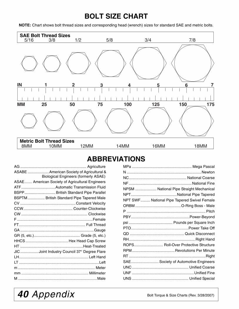
BOLT SIZE CHARTNOTE: Chart shows bolt thread sizes and corresponding head (wrench) sizes for standard SAE and metric bolts.
ABBREVIATIONSAG .............................................................. AgricultureASABE ....................American Society of Agricultural &
Biological Engineers (formerly ASAE)ASAE....... American Society of Agricultural EngineersATF................................Automatic Transmission FluidBSPP............................. British Standard Pipe ParallelBSPTM................ British Standard Pipe Tapered MaleCV ....................................................Constant VelocityCCW.............................................. Counter-ClockwiseCW .............................................................. ClockwiseF .......................................................................FemaleFT.............................................................. Full ThreadGA .....................................................................GaugeGR (5, etc.)........................................... Grade (5, etc.)HHCS ........................................ Hex Head Cap ScrewHT ...........................................................Heat-TreatedJIC................. Joint Industry Council 37° Degree FlareLH................................................................. Left HandLT ...........................................................................Leftm ........................................................................ Metermm ............................................................... MillimeterM ..........................................................................Male
MPa ........................................................ Mega Pascal
N ......................................................................Newton
NC...................................................... National Coarse
NF ...........................................................National Fine
NPSM .................... National Pipe Straight Mechanical
NPT...........................................National Pipe Tapered
NPT SWF......... National Pipe Tapered Swivel Female
ORBM ...........................................O-Ring Boss - Male
P .......................................................................... Pitch
PBY.......................................................Power-Beyond
psi ......................................... Pounds per Square Inch
PTO......................................................Power Take Off
QD ................................................... Quick Disconnect
RH.............................................................. Right Hand
ROPS........................... Roll-Over Protective Structure
RPM........................................Revolutions Per Minute
RT ........................................................................Right
SAE.......................... Society of Automotive Engineers
UNC ..................................................... Unified Coarse
UNF ..........................................................Unified Fine
UNS ..................................................... Unified Special
5/16 3/8 1/2 5/8 3/4 7/8SAE Bolt Thread Sizes
MM 25 50 75 100 125 150 175
IN 1 7
Metric Bolt Thread Sizes8MM 18MM14MM12MM10MM 16MM
2 3 4 5 6
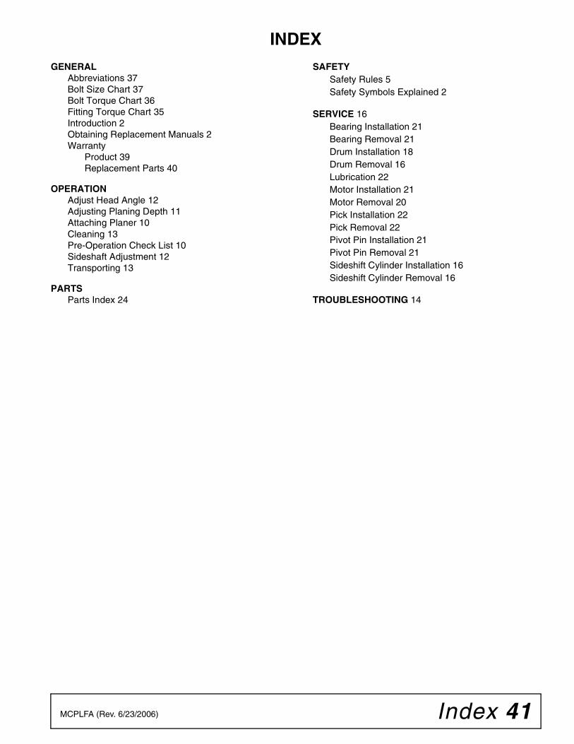
Index 41MCPLFA (Rev. 6/23/2006)
INDEXGENERAL
Abbreviations 37Bolt Size Chart 37Bolt Torque Chart 36Fitting Torque Chart 35Introduction 2Obtaining Replacement Manuals 2Warranty
Product 39Replacement Parts 40
OPERATIONAdjust Head Angle 12Adjusting Planing Depth 11Attaching Planer 10Cleaning 13Pre-Operation Check List 10Sideshaft Adjustment 12Transporting 13
PARTSParts Index 24
SAFETYSafety Rules 5Safety Symbols Explained 2
SERVICE 16Bearing Installation 21Bearing Removal 21Drum Installation 18Drum Removal 16Lubrication 22Motor Installation 21Motor Removal 20Pick Installation 22Pick Removal 22Pivot Pin Installation 21Pivot Pin Removal 21Sideshift Cylinder Installation 16Sideshift Cylinder Removal 16
TROUBLESHOOTING 14

F-3079 (Rev. 5/15/2008)
WARRANTY(All Models Except Mow’n MachineTM Zero-Turn Mowers and Woods BoundaryTM Utility Vehicles)
Please Enter Information Below and Save for Future Reference.
Date Purchased: ____________________________ From (Dealer): ___________________________________________
Model Number: ____________________________ Serial Number: ___________________________________________
Woods Equipment Company (“WOODS”) warrants this product to be free from defect in material and workmanship. Except as otherwise setforth below, the duration of this Warranty shall be for TWELVE (12) MONTHS COMMENCING ON THE DATE OF DELIVERY OF THEPRODUCT TO THE ORIGINAL PURCHASER.
Woods backhoe models BH70-X, BH80-X, and BH90-X are warranted for two (2) years from the date of delivery to the original purchaser.
The warranty periods for specific parts or conditions are listed below:
Under no circumstances will this Warranty apply in the event that the product, in the good faith opinion of WOODS, has been subjected toimproper operation, improper maintenance, misuse, or an accident. This Warranty does not apply in the event that the product has beenmaterially modified or repaired by someone other than WOODS, a WOODS authorized dealer or distributor, and/or a WOODS authorizedservice center. This Warranty does not cover normal wear or tear, or normal maintenance items. This Warranty also does not cover repairs madewith parts other than those obtainable through WOODS.
This Warranty is extended solely to the original purchaser of the product. Should the original purchaser sell or otherwise transfer this product toa third party, this Warranty does not transfer to the third party purchaser in any way. There are no third party beneficiaries of this Warranty.
WOODS makes no warranty, express or implied, with respect to engines, batteries, tires or other parts or accessories not manufactured byWOODS. Warranties for these items, if any, are provided separately by their respective manufacturers.
WOODS’ obligation under this Warranty is limited to, at WOODS’ option, the repair or replacement, free of charge, of the product if WOODS,in its sole discretion, deems it to be defective or in noncompliance with this Warranty. The product must be returned to WOODS with proofof purchase within thirty (30) days after such defect or noncompliance is discovered or should have been discovered, routed through thedealer and distributor from whom the purchase was made, transportation charges prepaid. WOODS shall complete such repair orreplacement within a reasonable time after WOODS receives the product. THERE ARE NO OTHER REMEDIES UNDER THISWARRANTY. THE REMEDY OF REPAIR OR REPLACEMENT IS THE SOLE AND EXCLUSIVE REMEDY UNDER THISWARRANTY.
THERE ARE NO WARRANTIES WHICH EXTEND BEYOND THE DESCRIPTION ON THE FACE OF THIS WARRANTY. WOODSMAKES NO OTHER WARRANTY, EXPRESS OR IMPLIED, AND WOODS SPECIFICALLY DISCLAIMS ANY IMPLIED WARRANTYOF MERCHANTABILITY AND/OR ANY IMPLIED WARRANTY OF FITNESS FOR A PARTICULAR PURPOSE.
WOODS shall not be liable for any incidental or consequential losses, damages or expenses, arising directly or indirectly from theproduct, whether such claim is based upon breach of contract, breach of warranty, negligence, strict liability in tort or any other legaltheory. Without limiting the generality of the foregoing, Woods specifically disclaims any damages relating to (i) lost profits, business,revenues or goodwill; (ii) loss of crops; (iii) loss because of delay in harvesting; (iv) any expense or loss incurred for labor, supplies, substitutemachinery or rental; or (v) any other type of damage to property or economic loss.
This Warranty is subject to any existing conditions of supply which may directly affect WOODS’ ability to obtain materials or manufacturereplacement parts.
No agent, representative, dealer, distributor, serviceperson, salesperson, or employee of any company, including without limitation, WOODS,its authorized dealers, distributors, and service centers, is authorized to alter, modify, or enlarge this Warranty.
Answers to any questions regarding warranty service and locations may be obtained by contacting:
Part or Condition Warranted
Model Number Duration (from date of delivery to the original purchaser)
Gearbox components
BW1260, BW1800 8 years
BB48X, BB60X, BB72X, BB84X, BB600X, BB720X, BB840X, BB6000X,BB7200X, BB8400X, DS1260, DSO1260, DS1440, TS1680, BW126-3, BW180-3 6 years
PHD25, PHD35, PHD65, PHD95, 2162, 3240, DS96, DS120, RCC42, RM550-2,RM660-2, RM990-3, PRD6000, PRD7200, PRD8400, 7144RD-2, 9180RD-2,9204RD-2, S15CD, S20CD, S22CD, S25CD, S27CD
5 years
RDC54, RD60, RD72 3 years (1 year if used in rental or commercial applications)
Blade spindles RM550-2, RM660-2, RM990-3, PRD6000, PRD7200, PRD8400, 7144RD-2,9180RD-2, 9204RD-2 3 years
Rust-through BB600, BB720, BB840, BB6000, BB7200, BB8400, BW126-3, BW180-3,BW1260, BW1800, 2162, 3240, DS1260, DSO1260, DS1440, TS1680 10 years

F-8494 (Rev. 6/23/2005)
WARRANTY(Replacement Parts For All Models Except Mow’n MachineTM
Zero-Turn Mowers and Woods BoundaryTM Utility Vehicles)
Woods Equipment Company (“WOODS”) warrants this product to be free from defect in material andworkmanship for a period of ninety (90) days from the date of delivery of the product to the originalpurchaser with the exception of V-belts, which will be free of defect in material and workmanship for aperiod of 12 months.
Under no circumstances will this Warranty apply in the event that the product, in the good faith opinion ofWOODS, has been subjected to improper operation, improper maintenance, misuse, or an accident. ThisWarranty does not cover normal wear or tear, or normal maintenance items.
This Warranty is extended solely to the original purchaser of the product. Should the original purchaser sellor otherwise transfer this product to a third party, this Warranty does not transfer to the third party purchaserin any way. There are no third party beneficiaries of this Warranty.
WOODS’ obligation under this Warranty is limited to, at WOODS’ option, the repair or replacement, free ofcharge, of the product if WOODS, in its sole discretion, deems it to be defective or in noncompliance withthis Warranty. The product must be returned to WOODS with proof of purchase within thirty (30)days after such defect or noncompliance is discovered or should have been discovered, routed throughthe dealer and distributor from whom the purchase was made, transportation charges prepaid.WOODS shall complete such repair or replacement within a reasonable time after WOODS receives theproduct. THERE ARE NO OTHER REMEDIES UNDER THIS WARRANTY. THE REMEDY OFREPAIR OR REPLACEMENT IS THE SOLE AND EXCLUSIVE REMEDY UNDER THISWARRANTY.
THERE ARE NO WARRANTIES WHICH EXTEND BEYOND THE DESCRIPTION ON THE FACE OFTHIS WARRANTY. WOODS MAKES NO OTHER WARRANTY, EXPRESS OR IMPLIED, ANDWOODS SPECIFICALLY DISCLAIMS ANY IMPLIED WARRANTY OF MERCHANTABILITY AND/OR ANY IMPLIED WARRANTY OF FITNESS FOR A PARTICULAR PURPOSE.
WOODS shall not be liable for any incidental or consequential losses, damages or expenses, arisingdirectly or indirectly from the product, whether such claim is based upon breach of contract, breachof warranty, negligence, strict liability in tort or any other legal theory. Without limiting the generalityof the foregoing, Woods specifically disclaims any damages relating to (i) lost profits, business, revenues orgoodwill; (ii) loss of crops; (iii) loss because of delay in harvesting; (iv) any expense or loss incurred forlabor, supplies, substitute machinery or rental; or (v) any other type of damage to property or economic loss.
This Warranty is subject to any existing conditions of supply which may directly affect WOODS’ ability toobtain materials or manufacture replacement parts.
No agent, representative, dealer, distributor, service person, salesperson, or employee of any company,including without limitation, WOODS, its authorized dealers, distributors, and service centers, is authorizedto alter, modify, or enlarge this Warranty.
Answers to any questions regarding warranty service and locations may be obtained by contacting:

PART NO.
MCPLFA
© 2001 Woods Equipment Company. All rights reserved. WOODS, the Woods logo, and "Tested. Proven. Unbeatable." are trademarks of WoodsEquipment Company. All other trademarks, trade names, or service marks not owned by Woods Equipment Company that appear in this manualare the property of their respective companies or mark holders. Specifications subject to change without notice.
Woods Equipment Company
2606 South Illinois Route 2Post Office Box 1000Oregon, Illinois 61061
800-319-6637 tel800-399-6637 faxwww.WoodsEquipment.com