Embed Size (px)
Citation preview

• Vibration sensors
• Sensor selection, installation and mounting
• Cables and connectors
• Mounting accessories
SKF Vibration Sensors Catalog
1PUB CM/P1 11604-14 EN April 2016

Introduction . . . . . . . . . . . . . . . . . . . . . . . . . . . . . . . . . . . . . . . 3
SKF – the knowledge engineering company . . . . . . . . . . . . . . 4
Overview for the SKF family of vibration sensors . . . . . . . . . . 7
Vibration sensor selection . . . . . . . . . . . . . . . . . . . . . . . . . . . . 8
Pulp and Paper . . . . . . . . . . . . . . . . . . . . . . . . . . . . . . . . . . . . . . 9
General purpose, food and beverage . . . . . . . . . . . . . . . . . . . . . 10
Oil and gas, refining, petrochemicals . . . . . . . . . . . . . . . . . . . . . 11
Power generation (fossil fuel, nuclear, hydro) . . . . . . . . . . . . . . . 12
Power generation (wind turbines) . . . . . . . . . . . . . . . . . . . . . . . . 13
Metalworking . . . . . . . . . . . . . . . . . . . . . . . . . . . . . . . . . . . . . . . 14
Mining, mineral processing and cement . . . . . . . . . . . . . . . . . . . 15
Specialized models for data collector / analyzer usage . . . . . . . . 16
Other specialized models . . . . . . . . . . . . . . . . . . . . . . . . . . . . . . 17
Industrial accelerometers for widespread applications . . . . . 18
Economical accelerometers . . . . . . . . . . . . . . . . . . . . . . . . . . . 27
Integral cable accelerometers . . . . . . . . . . . . . . . . . . . . . . . . . 32
Accelerometers with extended temperature range . . . . . . . . . 47
Combination vibration and temperature sensors . . . . . . . . . . 52
Hazardous area approved sensors . . . . . . . . . . . . . . . . . . . . . . 65
Velocity sensors . . . . . . . . . . . . . . . . . . . . . . . . . . . . . . . . . . . . 80
Portable analysis accelerometers . . . . . . . . . . . . . . . . . . . . . . 87
Special purpose sensors . . . . . . . . . . . . . . . . . . . . . . . . . . . . . . 96
Low frequency accelerometers . . . . . . . . . . . . . . . . . . . . . . . . . . 98
High frequency accelerometers . . . . . . . . . . . . . . . . . . . . . . . . . 104
Machine tool accelerometers . . . . . . . . . . . . . . . . . . . . . . . . . . . 106
Acceleration and AEE sensors . . . . . . . . . . . . . . . . . . . . . . . . . . . 110
Small diameter accelerometers . . . . . . . . . . . . . . . . . . . . . . . . . 112
High temperature accelerometers . . . . . . . . . . . . . . . . . . . . . . . 114
Vibration sensor installation and mounting requirements . . . 116
Vibration sensor cables and accessories . . . . . . . . . . . . . . . . . 125
Mounting hardware . . . . . . . . . . . . . . . . . . . . . . . . . . . . . . . . . 143
Contents
2 PUB CM/P1 11604-14 EN April 2016

The measurement of vibration is the most
common method of assessing the mechani-
cal status of machinery for condition moni-
toring purposes.
Although advances have been made in
the field of vibration monitoring and analysis
equipment, the selection of sensors and the
way they are installed on a machine remain
critical factors in determining the success of
any condition monitoring program. Invest-
ments made for installing superior sensors
are a prudent investment since the informa-
tion provided about the machine of interest
is accurate and reliable. Poor quality sensors
and inadequate installation can easily give
misleading data or, in some cases, cause a
critical machine condition to be completely
overlooked.
SKF has developed a range of industrial
vibration sensors that incorporates over
three decades of practical experience from
providing transducers such as eddy current
probe displacement sensors, accelerometers
and velocity sensors, to machinery monitor-
ing of all classes in multiple industries.
The measurements of vibrationThe three parameters representing motion
detected by vibration monitors are:
• Displacement
• Velocity
• Acceleration
These parameters can be measured by a
variety of motion sensors and are mathe-
matically related:
• Velocity is the first time derivative of dis-
placement
• Acceleration is the first time derivative of
velocity
Selection of a sensor proportional to dis-
placement, velocity or acceleration depends
upon the type and design of the equipment
that is to be monitored, the frequencies of
interest and the signal levels involved.
Accelerometers
The acceleration sensor is versatile, reliable
and the most popular vibration sensor for
machinery monitoring. For a given mechan-
ical acceleration level, piezoelectric acceler-
ometers have a constant signal over a wide
frequency range, typically up to 20 kHz, and
are very useful for all types of vibration
measurements. Acceleration integrated to
velocity can be used for low frequency mea-
surements. Acceleration signals in the high
frequency range added with various signal
processing techniques like Acceleration
Enveloping (gE) are very useful for bearing
and gear measurements.
The basic acceleration sensor has a good
signal to noise ratio over a wide dynamic
range. They are useful for measuring low to
very high frequencies and are available in a
wide variety of general purpose and applica-
tion specific designs.
When combined with vibration monitors
capable of integrating from acceleration to
velocity, accelerometers can be useful com-
ponents in a multi-parameter monitoring
program.
Sensor wiring, mounting hardware and accessoriesIn addition to sensor selection, sensor
mounting and wiring are important aspect
of vibration sensor installation. As with sen-
sors and monitoring equipment, using
superior installation components is a good
investment. Time and effort to troubleshoot
problems related to poor cabling and inferior
mounting can easily exceed the original cost
of an inferior installation.
SKF offers a comprehensive product line
of sensor wiring, mounting hardware and
accessories. These are the same compo-
nents that SKF uses in its own bearing
manufacturing plants and for customer sys-
tems that are installed and maintained
under SKF service contracts.
Introduction
Displacement sensors
Eddy current probes are non-contact sen-
sors primarily used to measure displace-
ment that reflects shaft radial vibration,
shaft/rotor position and clearance and rota-
tional speed. Also referred to as “proximity
probes” or “displacement probes”, eddy cur-
rent probes are typically applied on
machines utilizing sleeve/journal bearings.
They have excellent frequency response
with no lower frequency limit and can also
be used to provide a trigger input for phase-
related measurements. Eddy current probe
systems are the best solution for shaft posi-
tion measurements in sleeve bearing equip-
ment. The selection and specifications of
SKF’s range of eddy current probes is
detailed in a separate catalog.
Velocity sensors
Velocity sensors are used for low to medium
frequency measurements. They are useful
for vibration monitoring and balancing
operations on rotating machinery. As com-
pared to accelerometers, velocity sensors
have lower sensitivity to high frequency
vibrations. There are two types:
• Traditional, “self-generating” velocity sen-
sors or “velocity pickups”. These are of a
mechanical design that use an electro-
magnetic (coil and magnet) system to
generate the velocity signal. Their advan-
tage is a direct measurement of velocity.
Their disadvantages are that they wear
out over time, owing to the moving parts,
and are sensitive to mounting orientation.
• Piezoelectric velocity sensors (internally
integrated accelerometers). These are
more common today, as they have
improved capabilities over self-generating
types and are a more rugged and smaller
size design.
3PUB CM/P1 11604-14 EN April 2016

From one simple but
inspired solution to
a misalignment
problem in a textile
mill in Sweden, and
fifteen employees in
1907, SKF has
grown to become a
global industrial
knowledge leader.
Over the years we have built on our exper-
tise in bearings, extending it to seals, me-
chatronics, services and lubrication systems.
Our knowledge network includes 46 000
employees, 15 000 distributor partners,
offices in more than 130 countries, and a
growing number of SKF Solution Factory
sites around the world.
Research and development
We have hands-on experience in over forty
industries, based on our employees’ know-
ledge of real life conditions. In addition our
world-leading experts and university part-
ners who pioneer advanced theoretical
research and development in areas includ-
ing tribology, condition monitoring, asset
management and bearing life theory. Our
ongoing commitment to research and
devel opment helps us keep our customers
at the forefront of their industries.
Meeting the toughest challenges
Our network of knowledge and experience
along with our understanding of how our
core technologies can be combined helps
us create innovative solutions that meet the
toughest of challenges. We work closely with
our customers throughout the asset life
cycle, helping them to profitably and
re spon sibly grow their businesses.
SKF Solution Factory makes SKF knowledge and manu facturing expertise available locally, to provide unique solutions and services to our customers.
Working with SKF IT and logistics systems and application experts, SKF Authorized Distributors deliver a valuable mix of product and application knowledge to customers worldwide.
Working for a sustainable future
Since 2005, SKF has worked to reduce the
negative environmental impact from our
own operations and those of our suppliers.
Our continuing technology development
intro duced the SKF BeyondZero portfolio
of products and services which improve
efficiency and reduce energy losses, as well
as enable new technol ogies harnessing
wind, solar and ocean power. This combined
approach helps reduce the environmental
impact both in our own oper ations and in
our customers’.
SKF – the knowledge engineering company
4 PUB CM/P1 11604-14 EN April 2016

BearingsSKF is the world leader in the design, development and manufacture of high performance rolling bearings, plain bearings, bearing units and housings.
Machinery maintenanceCondition monitoring technologies and main-tenance services from SKF can help minimize unplanned downtime, improve operational efficiency and reduce maintenance costs.
Sealing solutionsSKF offers standard seals and custom engineered sealing solutions to increase uptime, improve machine reliability, reduce friction and power losses, and extend lubricant life.
MechatronicsSKF fly-by-wire systems for aircraft and drive-by-wire systems for off-road, agricultural and forklift applications replace heavy, grease or oil consuming mechanical and hydraulic systems.
Lubrication solutionsFrom specialized lubricants to state-of-the-art lubrication systems and lubrication management ser vices, lubrication solutions from SKF can help to reduce lubrication related downtime and lubricant consumption.
Actuation and motion controlWith a wide assortment of products – from actu-ators and ball screws to profile rail guides – SKF can work with you to solve your most pressing linear system challenges.
Our knowledge – your successSKF Life Cycle Management is how we combine our technology
platforms and advanced ser vices, and apply them at each stage
of the asset life cycle, to help our customers to be more
success ful, sustainable and profitable.
Working closely with you
Our objective is to help our customers
improve productivity, minimize main ten-
ance, achieve higher energy and resource
efficiency, and optimize designs for long
service life and reliability.
Innovative solutions
Whether the application is linear or rotary
or a combination of the two, SKF engineers
can work with you at each stage of the asset
life cycle to improve machine performance
by looking at the entire application. This
approach doesn’t just focus on individual
components like bearings or seals. It looks
at the whole application to see how each
com po nent interacts with the next.
Design optimization and verification
SKF can work with you to optimize current
or new designs with proprietary 3-D model-
ing software that can also be used as a vir-
tual test rig to confirm the integrity of the
design.
SKF Life Cycle Management
Design and developManufacture and test
Spec
ifica
tion
Install a
nd com
mis
sion
Operate and monitor
Maintain and repair
5PUB CM/P1 11604-14 EN April 2016

With the proper sensor to supply the critical operating information,
the machine operates in a safer condition for both the machine as
well as the personnel operating the machine.
Various machine operating conditions concerning temperature
extremes, magnetic fields, vibration range, frequency range, elec-
tromagnetic compatibility (EMC) and electrostatic discharge (ESD)
conditions and the required signal quality necessitate the need for a
variety of sensors.
The measurement of vibration is a complex subject. SKF has opti-
mized its selection of vibration sensors to obtain the best perfor-
mance, in a multiplicity of industrial applications, from its range of
vibration instrumentation systems, including:
• SKF Microlog portable data collectors/analyzers
• SKF Multilog On-line System DMx
• SKF Multilog On-line System IMx (-C, -M, -R, -S, -T, -W)
• SKF Multilog On-line System WMx
• SKF Machine Condition Transmitter (CMSS 500 series)
Overview for the SKF family of vibration sensors
��� Microlog GX series (CMXA 75)
SKF Microlog AX series (CMXA 80)
SKF Multilog On-line System DMx
SKF Multilog On-line System WMx
SKF Multilog On-line System IMx-M
SKF Multilog On-line System IMx-S
SKF Machine Condition Transmitter (CMSS 500 series)
6 PUB CM/P1 11604-14 EN April 2016

The range of vibration sensors offered is wide, as a vibration sensor
has many different characteristics that may vary, including mea-
surement related factors such as frequency response, sensitivity and
accuracy. Physical characteristics such as temperature rating, size
and connector orientation are also considerations.
The following is a guide to SKF’s experience in sensor use in the
most common industrial sectors in which vibration monitoring is
employed.
For each industry, the top four features required of a quality
vibration sensor are stated and explained. Industrial sensor choices
are graded:
• “Good” – A general purpose choice that has adequate measure-
ment and physical characteristics for condition monitoring pro-
grams, where data is trended for change and absolute precision is
not so important.
• “Better” – A general purpose choice that has adequate measure-
ment and physical characteristics for condition monitoring pro-
grams, but adds a specific feature such as an extended tempera-
ture range or mounting orientation better suited to the
application.
• “Best” – A premium choice that has optimum measurement and
physical characteristics, but also offers the longest history as evi-
dence of reliability. These are particularly suited to critical
machinery applications where the sensor may be used in safety-
related functions such as machinery protection.
Vibration sensor selection
7PUB CM/P1 11604-14 EN April 2016

Pulp and paper
Following are the top features required of a quality vibration sensor
in the pulp and paper industry, along with the reasons why:
• Low frequency response ≤ 1,0 Hz
– For low rotational speed of rolls
• Elevated temperature 120 to 150 °C (2 5 0 to 3 0 0 °F)
– For dryer section heat and humidity
• IP 68 cable/connector assembly
– For wet environment and frequent roll changes
• Good signal to noise ratio
– For bearing defect detection
Best – Elevated temperatures
CMSS 2200
CMSS 2106 CMSS 2207
CMSS 2100 CMSS 2100T
Good – General purpose monitoring Better – Installation robustness
CMSS 2200T
8 PUB CM/P1 11604-14 EN April 2016

General purpose, food and beverageFollowing are the top features required of a quality vibration sensor
in the food and beverage industry, along with the reasons why:
• Low frequency response ≤ 1,0 Hz
– For low rotational speed of machines
• Small physical size
– Small bearing and access restrictions
• Corrosion precautions
– Cleaning fluid and chemical attack
• Integral cable or IP 68 connector/cable
– Frequent hose-down environment
Good – General purpose monitoring
Best – Frequency and precision
Better – Installation robustness
CMSS 797T-1
CMSS 780C CMSS 2100F
CMSS 2100 CMSS 793T-3 CMSS 2200
9PUB CM/P1 11604-14 EN April 2016

Oil and gas, refining, petrochemicalsFollowing are the top features required of a quality vibration sensor
in the oil and gas, refining and petrochemicals industries:
• ATEX/NEC certification
– Hazardous area
• Minimum 10 Hz to 10 kHz frequency response
– For turbines, blades and gears
• ±5% sensitivity precision
– May be used for API 670 machine trip
• High EMI/RFI shielding
– May be used for API 670 machine trip
Good – Monitoring in Class I, Division 2 areas
Best – High precision and long experience
Better – Monitoring in Intrinsically Safe areas
CMSS 793-EE (-FM, -CA) CMSS 797-EE (-FM, -CA) CMSS 793V-EE (-FM, -CA)
CMSS 786A-D2 CMSS 787A-D2 CMSS 786T-D2 CMSS 786F-D2 CMSS 786A-IS CMSS 787A-IS CMSS 786T-IS CMSS 786F-IS
10 PUB CM/P1 11604-14 EN April 2016

Industrial accelerometers for widespread applications• CMSS 2100 Industrial accelerometer, straight exit
• CMSS 2200 / CMSS 2200-M8 Industrial accelerometer, side exit
• CMSS 793 Superior accelerometer, straight exit
• CMSS 797 Superior accelerometer, side exit
���� 2 1 0 0 ���� �� � ��������� ���� 7 9 3
���� 7 9 7
11PUB CM/P1 11604-14 EN April 2016

The CMSS 2100 accelerometer is a good multi-purpose sensor. The
sensor is most commonly deployed in the following industries:
• Power Generation (Fossil, Nuclear, Hydro)
• Pulp and Paper
• Food and Beverage
Features• For use with all SKF on-line systems, protection systems and the
portable data collection instruments
• Rugged, economical and all around general purpose sensor
• 100 mV/g sensitivity to optimize use in multiple applications
• Exceptional bias voltage (BV) stability at elevated temperatures
• Designed for exceptional low noise level over a wide temperature
range
• Meets stringent CE, EMC requirements
• Two mounting studs (1/4-28 and M8 × 1,25) provided
• Corrosion resistant and hermetically sealed for installation in high
humidity areas
• Reverse polarity wiring protection
Recommended connector/cable assembly
• CMSS 932 series
SpecificationsSpecifications conform to ISA-RP-37.2 (1-64) and are typical values
referenced at 24 °C (75 °F), 24 V DC supply, 4 mA constant current
and 100 Hz.
Dynamic
• Sensitivity: 100 mV/g
• Sensitivity precision: ±5% at 25 °C (75 °F)
• Acceleration range: 80 g peak
• Amplitude linearity: ≤ 1%, up to full scale
• Frequency range:
– ±5%: 3,0 to 5 000 Hz
– ±10%: 1,0 to 9 000 Hz
– ±3 dB: 0,5 to 14 000 Hz
• Resonance frequency, mounted, nominal: 30 kHz
• Transverse sensitivity: ≤ 5% of axial
• Temperature response: See graph
CMSS 2100Industrial accelerometer, straight exit
Dimensions
MODEL CMSS2100
S/N S00000
A B
Two pin connector
53,0 mm (2.10 in.)
20,3 mm (0.80 in.)
22,3 mm (0.87 in.)
19,0 mm (0.75 in.)
1/4-28 mounting hole
7/8 in. hex
Limited
Lifetime
WARRANTY
Electrical
• Power requirements:
– Voltage source: 24 V DC nominal, 18 to 30 V DC
– Constant current diode: 2 to 10 mA, recommended 4 mA
• Electrical noise:
– 2,0 Hz: 20 µg/√Hz
• Output impedance: < 100 Ω
• Bias output voltage: 12 V DC
• Grounding: Case isolated, internally shielded
12 PUB CM/P1 11604-14 EN April 2016

Physical
• Dimensions: See drawing
• Weight: 90 g (3.2 oz.)
• Case material: 316L stainless steel
• Mounting:
– Internal 1/4-28 thread
– M8 × 1,25 and 1/4-28 to 1/4-28 mounting studs provided
• Mounting torque: 2,9 Nm (24 in. lbs.)
• Connections:
– Pin A: Signal/Power
– Pin B: Common
• Mating connector: CMSS 932-68LC or CMSS 932-68TL, two pin,
IP 68, locking collar or twist lock
• Recommended cable: CMSS 932-SY-XXM and
CMSS 932-DY-XXM, two conductor, twisted pair, single or double
shielded, yellow
Environmental
• Temperature range: –50 to +120 °C (–60 to +250 °F) operating
temperature
• Vibration limit: 500 g peak
• Shock limit: 5 000 g peak
• Electromagnetic sensitivity, equivalent g, maximum: 70 µg/gauss
• Sealing: Hermetic
• Base strain sensitivity: 200 µg/µstrain
• CE: According to the generic immunity standard for Industrial
Environment EN 50082-2
– Acceptance criteria: The generated “false equivalent g level”
under the above test conditions should be less than 2 mg
measured peak to peak
Ordering information
CMSS 2100 Industrial accelerometer, straight exit with MIL-C-5015 two pin connector.• 1/4-28 and M8 mounting studs provided. Calibration sensitivity and
nominal sensitivity is provided for each accelerometer package.• For corresponding cables, refer to the section Vibration sensor cables
and accessories († page 127).
Typical temperature response
Temperature, °C (°F)
Deviation, % sensitivity
+10
+5
0
–5
–10
–50 0 +50 +100 +120
(–60) (+30) (+120) (+210) (+250)
Typical frequency response
Frequency, Hz
Deviation, dB
3
2
1
0
–1
–2
–30.5 1 10 100 1 k 10 k
13PUB CM/P1 11604-14 EN April 2016

The CMSS 2200 accelerometer is a good multi-purpose sensor. The
sensor is most commonly deployed in the following industries:
• Power Generation (Fossil, Nuclear, Hydro)
• Pulp and Paper
• Mineral Processing
• Food and Beverage
Features• For use with all SKF on-line systems, protection systems and the
portable data collection instruments
• Rugged, economical and all around general purpose sensor
• 100 mV/g sensitivity to optimize use in multiple applications
• Exceptional bias voltage (BV) stability at elevated temperatures
• Designed for exceptional low noise level over a wide temperature
range
• Meets stringent CE, EMC requirements
• Captive mounting bolts (1/4-28, M6 × 1,00 or M8 × 1,25) provided
• Corrosion resistant and hermetically sealed for installation in high
humidity areas
• Reverse polarity wiring protection
Recommended connector/cable assembly
• CMSS 932 series
SpecificationsSpecifications conform to ISA-RP-37.2 (1-64) and are typical values
referenced at 24 °C (75 °F), 24 V DC supply, 4 mA constant current
and 100 Hz.
Dynamic
• Sensitivity: 100 mV/g
• Sensitivity precision: ±5% at 24 °C (75 °F)
• Acceleration range: 80 g peak
• Amplitude linearity: 1%
• Frequency range:
– ±10%: 1,0 to 5 000 Hz
– ±3 dB: 0,7 to 10 000 Hz
• Resonance frequency, mounted, minimum: 22 kHz
• Transverse sensitivity: ≤ 5% of axial
• Temperature response: See graph
CMSS 2200 / CMSS 2200-M8Industrial accelerometer, side exit
Dimensions
MODEL CMSS2200MODEL CMSS2200-M8
S/N S0000
Two pin connector MIL-C-5015
1/4 in. socket head captive screw
CMSS 2200: 1/4-28 mounting thread CMSS 2200-M8: M8 mounting thread
53,0 mm (2.10 in.)
37,0 mm (1.44 in.)
25,0 mm (1.00 in.)
40,0 mm (1.60 in.)
26,0 mm (1.04 in.)
23,0 mm (0.92 in.)
6,3 mm (0.25 in.)
Limited
Lifetime
WARRANTY
Electrical
• Power requirements:
– Voltage source: 18 to 30 V DC
– Constant current diode: 2 to 10 mA, recommended 4 mA
• Electrical noise:
– 2,0 Hz: 20 µg/√Hz
• Output impedance: < 100 Ω
• Bias output voltage: 12 V DC
• Grounding: Case isolated, internally shielded
14 PUB CM/P1 11604-14 EN April 2016

Economical accelerometers• CMSS 780C / CMSS 780C-M8 Small economical accelerometer, straight exit
• CMSS 2100-M12 Industrial accelerometer, straight exit, with M12 connector
CMSS 780C /CMSS 780C-M8
CMSS 2100-M12
15PUB CM/P1 11604-14 EN April 2016

The CMSS 780C is a cost-effective, small sensor for use with
portable data collector routes found in the following industries:
• General Industry
• Food and Beverage
Common applications include general purpose machines such as
pumps, motors, fans and gearboxes, where a trend of normal condi-
tion is the main measurement objective, rather than absolute sensi-
tivity precision.
Features• For use with all SKF on-line surveillance systems and portable
data collection instruments
• Economical top-exit design
• Small physical size
• Rugged corrosion resistant and hermetically sealed
• Case isolated
• Meets stringent CE, EMC requirements
• ESD protection
• Reverse wiring protection
Recommended connector/cable assembly
• CMSS 932 series
Specifications
Dynamic
• Sensitivity: 100 mV/g
• Sensitivity precision: ±15% at 25 °C (75 °F)
• Acceleration range: 80 g peak
• Amplitude non-linearity: 1%
• Frequency range:
– ±5%: 1,0 to 7 000 Hz
– ±10%: 0,7 to 9 000 Hz
– ±3 dB: 0,4 to 14 000 Hz
• Resonance frequency, mounted, nominal: 30 kHz
• Transverse sensitivity: ≤ 5% of axial
• Temperature sensitivity:
– –50 °C (–60 °F): –5%
– +120 °C (+250 °F): +5%
CMSS 780C / CMSS 780C-M8Small economical accelerometer, straight exit
Dimensions
46,0 mm (1.81 in.) MODEL CMSS780C
S/N 1004
17,5 mm (0.69 in.)
Two pin connector MIL-C-5015
11/16 in. hex
1/4-28 mounting hole
Electrical
• Power requirements:
– Voltage source: 18 to 30 V DC
– Constant current diode: 2 to 10 mA
• Electrical noise:
– Broadband:
· 2,5 Hz to 25 kHz: 500 µg
– Spectral:
· 10 Hz: 7 µg/√Hz
· 100 Hz: 4 µg/√Hz
· 1 000 Hz: 2 µg/√Hz
• Output impedance: < 100 Ω
• Bias output voltage: 12 V DC
• Grounding: Case isolated, internally shielded
16 PUB CM/P1 11604-14 EN April 2016

Physical
• Dimensions: See drawing
• Weight: 62 g (2.2 oz.)
• Case material: 316L stainless steel
• Sensing element design: PZT ceramic/shear
• Mounting:
– CMSS 780C: 1/4-28 stud
– CMSS 780C-M8: 1/4-28 to M8 stud
• Connections:
– Sensor casing to ground
– Pin A: Power/Signal
– Pin B: Common
• Output connector: Two pin, MIL-C-5015 style
• Mating connector/cable: CMSS 932 series
• Recommended cable: CMSS 932-SY-XXM and
CMSS 932-DY-XXM, two conductor, twisted pair, single or double
shielded, yellow
Ordering information
CMSS 780C Small economical accelerometer, straight exit with 1/4-28 stud.CMSS 780C-M8 Small economical accelerometer, straight exit with 1/4-28 to M8 stud.• A calibration data certificate with the actual sensitivity of the
accelerometer is included in each package. The nominal sensitivity is etched on each unit.
Environmental
• Temperature range: –50 to +120 °C (–60 to +250 °F)
• Vibration limit: 500 g peak
• Shock limit: 5 000 g peak
• Electromagnetic sensitivity, equivalent g, maximum: 70 µg/gauss
• Sealing: Hermetic
• Base strain sensitivity: 0,0002 g/µstrain
• CE: According to the generic immunity standard for Industrial
Environment EN 50082-2
– Acceptance criteria: The generated “false equivalent g level”
under the above test conditions should be less than 2 mg
measured peak to peak
17PUB CM/P1 11604-14 EN April 2016

The CMSS 2100-M12 is a cost-effective sensor ideal for light to
medium-duty applications where vibration measurements are
required. The CMSS 2100-M12 is typically used in the following
industries:
• Automation
• Food and Beverage
• Power Generation
Common applications include general purpose machines such as
pumps, motors and fans.
Features• For use with all SKF on-line systems, protection systems and
switch box applications
• M12 four-pin connector
• Rugged, corrosion resistant and hermetically sealed for
installation in high humidity areas
• 100 mV/g sensitivity to optimize use in multiple applications
• Mounting studs provided (1/4-28 stud and 1/4-28 to M8 adapter
mounting stud)
Recommended connector/cable assembly
• CMSS R75SI-J9T2A-XX (length in feet)
Connector/cable assembly description: Cable connector assembly
with M12 connector, two-wire, IP 68 rated, shielded, various
lengths.
MODEL CMSS2100-M12
S/N S00000
Dimensions
Connector key
19,0 mm (0.75 in.)
22,2 mm (0.87 in.)
across flats
21,8 mm (0.86 in.)
M8 × 1,25 adapter mounting stud or1/4-28 mounting stud
M12 four-pin connector
47,0 mm (1.85 in.)
1
4
2
3
CMSS 2100-M12Industrial accelerometer, straight exit, with M12 connector
Limited
Lifetime
WARRANTY
18 PUB CM/P1 11604-14 EN April 2016

Specifications
Dynamic
• Sensitivity: 100 mV/g
• Sensitivity precision: ±5% at 25 °C (75 °F)
• Acceleration range: 80 g peak
• Amplitude linearity: 1%
• Frequency range:
– ±5%: 3,0 to 5 000 Hz
– ±10%: 1,0 to 9 000 Hz
– ±3 dB: 0,5 to 14 000 Hz
• Resonance frequency, mounted, minimum: 30 kHz
• Transverse sensitivity: ≤ 5% of axial
• Temperature response:
– –25 °C (–15 °F): –10%
– +120 °C (+250 °F): +10%
Electrical
• Power requirements:
– Voltage source: 18 to 30 V DC
– Constant current diode: 2 to 10 mA, recommended 4 mA
• Electrical noise, equivalent g:
– Broadband:
· 2,5 Hz to 25 kHz: 700 µg
– Spectral:
· 10 Hz: 10 µg/√Hz
· 100 Hz: 5 µg/√Hz
· 1 000 Hz: 5 µg/√Hz
• Output impedance: < 100 Ω
• Bias output voltage, nominal: 12 V DC
• Grounding: Case isolated, internally shielded
Environmental
• Temperature range: –50 to +120 °C (–60 to +250 °F) operating
temperature
• Vibration limit: 500 g peak
• Shock limit: 5 000 g peak
• Electromagnetic sensitivity, equivalent g, maximum: 70 µg/gauss
• Sealing: Hermetic
• Base strain sensitivity: 200 µg/µstrain
Physical
• Dimensions: See drawing
• Weight: 90 g (3.2 oz.)
• Case material: 316L stainless steel
• Mounting: 1/4-28 and 1/4-28 to M8 mounting studs provided
• Mounting torque: 3,4 Nm (30 in. lbs.)
• Connections:
– Shell: Ground
– Pin 1: Power/Signal
– Pin 2: Common
– Pin 3: N/C
– Pin 4: N/C
• Mating connector: M12-style
Typical frequency response
Frequency, Hz
Deviation, dB
3
2
1
0
–1
–2
–30.5 1 10 100 1 k 10 k
Ordering information
CMSS 2100-M12 Industrial accelerometer, straight exit with M12 connector, with 1/4-28 and M8 mounting studs.• A calibration data certificate with the actual sensitivity of the
accelerometer is included in each package. The nominal sensitivity is etched on each unit.
Typical temperature response
Temperature, °C (°F)
Deviation, % sensitivity+20
+10
0
–10
–20
–25 0 +25 +50 +75 +100 +120
(–15) (+30) (+75) (+120) (+170) (+210) (+250)
19PUB CM/P1 11604-14 EN April 2016

Integral cable accelerometers• CMSS 2100F Accelerometer with integral cable, straight exit
• CMSS 2200F Industrial accelerometer with integral cable, side exit
• CMSS 2110 Accelerometer with integral, braided cable, straight exit
• CMSS 2110-3 Accelerometer with integral, braided cable, straight exit
• CMPT 2310 Accelerometer for mining industry, with integral, braided cable, side exit
• CMPT 2323 Accelerometer for mining industry, with integral, braided cable, side exit
• CMSS WIND-100-10 Small accelerometer for wind turbines, with integral cable, side exit
CMSS 2100F CMSS 2110
CMSS 2310
CMSS 2110-3
CMSS 2323
CMSS 2200F
CMSS WIND-100-10
20 PUB CM/P1 11604-14 EN April 2016

CMSS 2100FAccelerometer with integral cable, straight exit
The CMSS 2100F accelerometer is a good multi-purpose sensor
with integral cable for light to medium-duty applications in the
following industries:
• Food and Beverage
Common applications include general purpose machines such as
pumps, motors and fans.
Features• For use with all SKF on-line systems, protection systems and the
portable data collection instruments
• Economical, top exit design
• Rugged, corrosion resistant and hermetically sealed
• Case isolation
• Meets stringent CE, EMC requirements
• ESD protection
• Reverse wiring protection
Specifications
Dynamic
• Sensitivity: 100 mV/g
• Sensitivity precision: ±5% at 25 °C (75 °F)
• Acceleration range: 80 g peak
• Amplitude linearity: 1%
• Frequency range:
– ±10%: 1,0 to 8 000 Hz
– ±3 dB: 0,5 to 13 000 Hz
• Resonance frequency, mounted, nominal: 30 kHz
• Transverse sensitivity: ≤ 5% of axial
• Temperature response: See graph
Electrical
• Power requirements:
– Voltage source1): 18 to 30 V DC
– Constant current diode1), 2): 2 to 10 mA
• Electrical noise:
– Broadband:
· 2,5 Hz to 25 kHz: 700 µg
– Spectral:
· 10 Hz: 10 µg/√Hz
· 100 Hz: 5 µg/√Hz
· 1 000 Hz: 5 µg/√Hz
• Output impedance: < 100 Ω
• Bias output voltage: 12 V DC
• Grounding: Case isolated, internally shielded
Dimensions
MODEL CMSS2100F
S/N S00000
Fluorine based polymer cable
42,7 mm (1.68 in.)
strain relief boot
45,0 mm (1.77 in.)
19,0 mm (0.75 in.)
37,5 mm (1.50 in.) minimum
bend diameter
70,0 mm (2.80 in.)
Hermetically sealed feed-through assembly
7/8 in. hex
1/4-28 mounting hole
21PUB CM/P1 11604-14 EN April 2016

Ordering information
CMSS 2100F Accelerometer with 5 meter (16,4 ft) integral cable, straight exit.
CMSS 2100F-33 Accelerometer with 10 meter (33 ft) integral cable, straight exit.
CMSS 2100F-50 Accelerometer with 15 meter (50 ft) integral cable, straight exit.
CMSS 2100F-66 Accelerometer with 20 meter (66 ft) integral cable, straight exit.
CMSS 2100F-100 Accelerometer with 30 meter (100 ft) integral cable, straight exit.
CMSS 2100F-XX (ft) Accelerometer with custom integral cable length, straight exit, in 10-meter (33 ft) increments.
Physical
• Dimensions: See drawing
• Weight: 90 g (3.2 oz.)
• Case material: 316L stainless steel
• Mounting: Internal 1/4-28 thread
• Mounting torque: 2,9 Nm (24 in. lbs.)
• Connections:
– Power/Signal: White
– Common: Black
– Case: Shield
• Integral cable: Fluorine based polymer, 5 m (16.4 ft.) blunt cut
1) To minimize the possibility of signal distortion when driving long cables with high vibration signals, 24 to 30 V DC powering is recommended. The higher level constant current source should be used when driving long cables (please consult SKF).
2) A maximum current of 6 mA is recommended for operating temperatures in excess of 100 °C (210 °F).
Environmental
• Temperature range: –50 to +120 °C (–60 to +250 °F) operating
temperature
• Vibration limit: 500 g peak
• Shock limit: 5 000 g peak
• Electromagnetic sensitivity, equivalent g maximum: 70 µg/gauss
• Sealing: Hermetic
• Base strain sensitivity: 0,0002 g/µstrain
• Hydrostatic pressure: 100 psi
• CE: According to the generic immunity standard for Industrial
Environment EN 50082-2
– Acceptance criteria: The generated “false equivalent g level”
under the above test conditions should be less than 2 mg
measured peak to peak
Typical temperature response
Temperature, °C (°F)
Deviation, % sensitivity+10
+5
0
–5
–10
–50 0 +50 +100 +120
(–60) (+30) (+120) (+210) (+250)
Typical frequency response
Frequency, Hz
Deviation, dB
3
2
1
0
–1
–2
–30.5 1 10 100 1 k 10 k
• 1/4-28 and M8 mounting studs provided. Calibration sensitivity is provided for each accelerometer package with nominal sensitivity etched on each unit.
22 PUB CM/P1 11604-14 EN April 2016

CMSS 2200FIndustrial accelerometer with integral cable, side exit
The CMSS 2200 accelerometer is a good multi-purpose sensor. The
integral cable delivers a tight connection to the sensor.
The sensor is commonly deployed in the following industries:
• Power Generation
• Mineral Processing
• Food and Beverage
Features• For use with all SKF on-line systems and protection systems
• Rugged, economical and all around general purpose sensor
• Standard 100 mV/g sensitivity to optimize use in multiple applica-
tions
• Designed for execptional low noise level over a wide tempeature
range
• Meets stringent CE, EMC requirements
• Captive mounting bolts (1/4-28 and M6 ™ 1.00) provided
• Corrosion resitant and hermitaclly sealed for submersion in water
up to 65 meter depth
• Reverse polarity wiring protection
• Mounts in any orientation
Specifications
Dynamic
• Sensitivity: 100 mV/g
• Sensitivity precision: ±10% at 24 °C (75 °F)
• Acceleration range: 80 g peak
• Amplitude nonlinearity: 1%
• Frequency range:
– ±10%: 1.0 to 5,000 Hz
– ±3 dB: 0.7 to 10,000 Hz
• Resonance frequency, mounted: 22 kHz
• Transverse sensitivity: ≤ 5% of axial
• Temperature response: See graph
MODEL CMSS2200FS/N S0000
Dimensions
42,7 mm(1.68 in.)
strain relief boot
30,2 mm(1.19 in.)
37,5 mm(1.50 in.)minimum
bend diameter
45,5 mm(1.79 in.)
1/4-28mounting thread
1/4 in. socket head captive screw
26,4 mm(1.04 in.)
23,4 mm(0.92 in.)
6,4 mm(0.25 in.)
24,9 mm(0.98 in.)
38,1 mm(1.50 in.)
Radius14,0 mm(0.55 in.)
Electrical
• Power requirement:
– Voltage source: 18 to 30 V DC
– Constant current diode: 2 to 10 mA
• Electrical noise, equivalent g:
– Broadband:
· 2.5 Hz to 25 kHz: 700 µg
Spectral:
· 10 Hz: 10 µg/√Hz
· 100 Hz: 5 µg/√Hz
· 1000 Hz: 5 µg/√Hz
• Output impedance: ≤ 100 Ω
• Bias output voltage: 12 V DC
• Grounding: Case isolated, internally shielded
23PUB CM/P1 11604-14 EN April 2016

Ordering information
CMSS 2200F Industrial accelerometer with 5 meter (16 feet) integral cable, side exit• 1/4-28 and M6 captive mounting bolts provided. Calibration
sensitivity and nominal sensitivity is provided for each accelerometer package.
CMSS 2200F-33 Industrial accelerometer with 10 meter (33 feet) integral cable, side exit
CMSS 2200F-66 Industrial accelerometer with 20 meter (66 feet) integral cable, side exit
Typical temperature response
Temperature, °C (°F)
Deviation, % sensitivity+10
+5
0
–5
–10
–50 0 +50 +100 +120
(–60) (+30) (+120) (+210) (+250)
Typical frequency response
Frequency, Hz
Deviation, dB
3
2
1
0
–1
–2
–30.5 1 10 100 1 k 10 k
Physical
• Dimensions: See drawing
• Weight: 145 g (5.1 oz.)
• Case material: 316L stainless steel
• Sensing element: PZT ceramic / shear
• Mounting: M6 and 1/4-28 captive mounting bolts
• Connections:
– White: Accelerometer power / signal
– Black: Accelerometer common
• Integral cabling: 5 meter (16 feet), blunt cut
Environmental
• Temperature range: –50 to +120 °C (–60 to +250 °F) operating
temperature
• Vibration limit: 500 g
• Shock limit: 5,000 g
• Electromagnetic sensitivity, equivalent g, maximum: 70 µg/gauss
• Sealing: Hermetic
• Base strain sensitivity: 2 mg/µstrain
• Hydrostatic pressure: 100 psi
24 PUB CM/P1 11604-14 EN April 2016
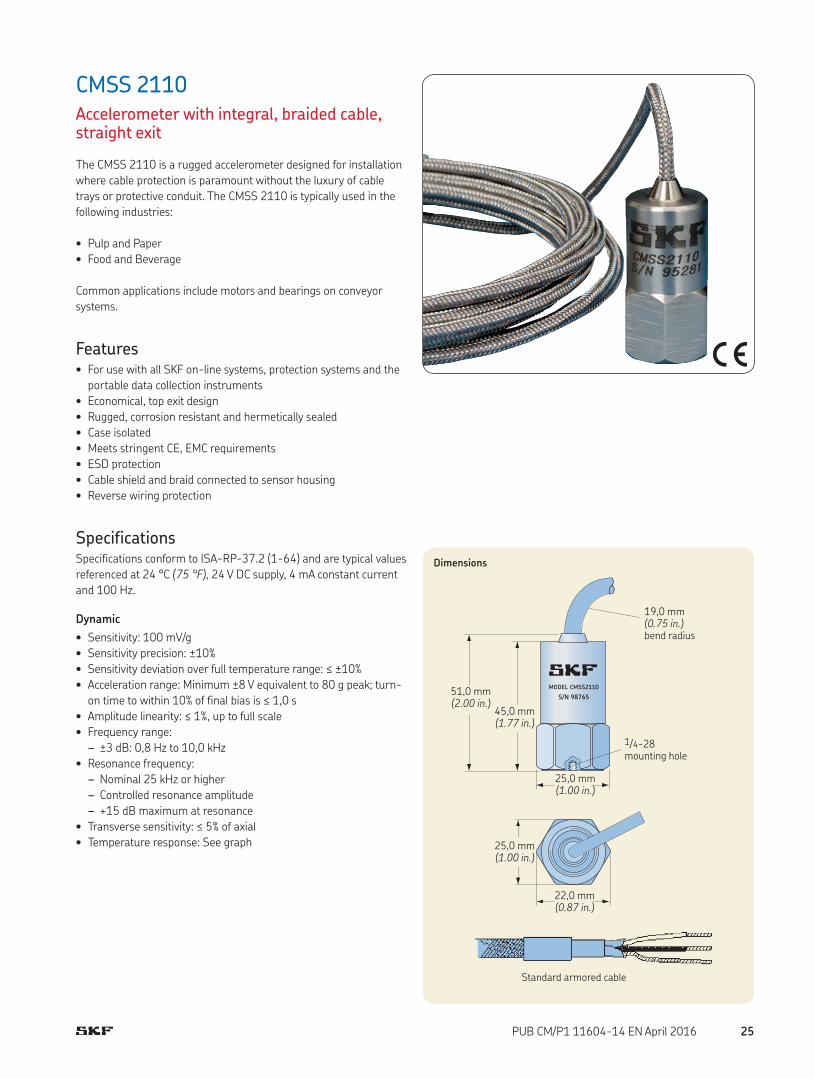
CMSS 2110Accelerometer with integral, braided cable, straight exit
The CMSS 2110 is a rugged accelerometer designed for installation
where cable protection is paramount without the luxury of cable
trays or protective conduit. The CMSS 2110 is typically used in the
following industries:
• Pulp and Paper
• Food and Beverage
Common applications include motors and bearings on conveyor
systems.
Features• For use with all SKF on-line systems, protection systems and the
portable data collection instruments
• Economical, top exit design
• Rugged, corrosion resistant and hermetically sealed
• Case isolated
• Meets stringent CE, EMC requirements
• ESD protection
• Cable shield and braid connected to sensor housing
• Reverse wiring protection
SpecificationsSpecifications conform to ISA-RP-37.2 (1-64) and are typical values
referenced at 24 °C (75 °F), 24 V DC supply, 4 mA constant current
and 100 Hz.
Dynamic
• Sensitivity: 100 mV/g
• Sensitivity precision: ±10%
• Sensitivity deviation over full temperature range: ≤ ±10%
• Acceleration range: Minimum ±8 V equivalent to 80 g peak; turn-
on time to within 10% of final bias is ≤ 1,0 s
• Amplitude linearity: ≤ 1%, up to full scale
• Frequency range:
– ±3 dB: 0,8 Hz to 10,0 kHz
• Resonance frequency:
– Nominal 25 kHz or higher
– Controlled resonance amplitude
– +15 dB maximum at resonance
• Transverse sensitivity: ≤ 5% of axial
• Temperature response: See graph
Dimensions
MODEL CMSS2110
S/N 98765
19,0 mm (0.75 in.) bend radius
51,0 mm (2.00 in.)
45,0 mm (1.77 in.)
1/4-28 mounting hole
25,0 mm (1.00 in.)
25,0 mm (1.00 in.)
22,0 mm (0.87 in.)
Standard armored cable
25PUB CM/P1 11604-14 EN April 2016

Physical
• Dimensions: See drawing
• Cable length: 5 m (16.4 ft.)
• Weight: 350 g (12.4 oz.), including cable
• Case material: 316L stainless steel
• Mounting:
– Internal 1/4-28 thread
– M8 × 1,25 and 1/4-28 to 1/4-28 mounting studs provided
• Mounting torque: 2,9 Nm (24 in. lbs.)
• Connections:
– Power signal: White
– Common: Black
– Shielding: Drain
• Cable:
– Integral cable, 5 m (16.4 ft.) long
– Shielded twisted pair; two times AWG 20
– Shield grounded to sensor housing
– Cable armored with stainless steel braid
– Braid also connected to sensor housing
– High temperature cable
– Cable diameter less than 5 mm (0.19 in.)
• Cable specifications: 2/C 20 AWG FEP/A/M/FEP 10-1254;
recommend two wire, twisted, shielded
Electrical
• Power requirements:
– Voltage source: 24 V DC nominal, ±20%
– Constant current diode: 2 to 10 mA, recommend 4 mA
• Electrical noise:
– Broadband (2,5 Hz to 25,0 kHz): < 0,6 mg RMS
• Output impedance: < 50 Ω
• Bias output voltage:
– 12,5 to 13,5 V DC for 24 V DC supply over temperature range
–50 to +100 °C (–60 to +210 °F)
– 11,0 to 14,0 V DC for 24 V DC supply over temperature range
100 to 120 °C (210 to 250 °F)
• Grounding:
– Case isolated, internally shielded (Faraday cage)
– The internal Faraday cage is connected to the signal return of
the shielded twisted pair
– The internal shield, as well as the stainless steel braid, is
connected to the sensor housing
• Isolation to sensor housing: > 10 MΩ over full temperature range
• Over-voltage protection
• Reverse polarity (wiring) protection
Environmental
• Temperature range: –50 to +120 °C (–60 to +250 °F) operating
temperature
• Vibration limit: 500 g peak
• Shock limit: 1 000 g peak
• Electromagnetic sensitivity, equivalent g, maximum:
< 100 µg/gauss at 50 to 60 Hz
• Base strain sensitivity: 200 µg/µstrain
• CE: According to the generic immunity standard for Industrial
Environment EN 50082-2
– Acceptance criteria: The generated “false equivalent g level”
under the above test conditions should be less than 2 mg
measured peak to peak
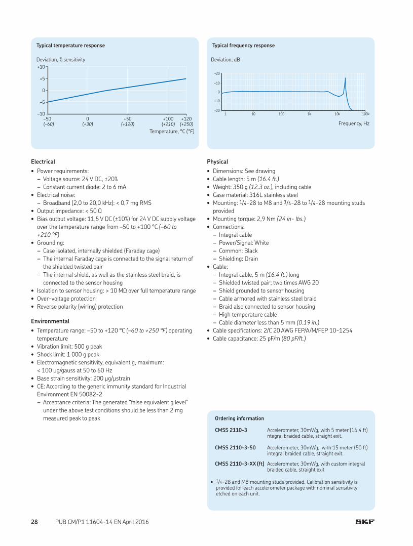
Typical frequency response
Frequency, Hz
Deviation, dB
+20
0
–20 1 10 100 1k 10k 100k
+10
–10
Typical temperature response
Temperature, °C (°F)
Deviation, % sensitivity
+10
+5
0
–5
–10
–50 0 +50 +100 +120
(–60) (+30) (+120) (+210) (+250)
Ordering information
CMSS 2110 Accelerometer with 5 meter (16,4 ft) overbraided integral cable, straight exit.
CMSS 2110-33 Accelerometer with 10 meter (33 ft) integral braided cable, straight exit.
CMSS 2110-50 Accelerometer with 15 meter (50 ft) integral braided cable, straight exit.
CMSS 2110-64 Accelerometer with 19,5 meter (66 ft) integral braided cable, straight exit.
CMSS 2110-100 Accelerometer with 30 meter (100 ft) integral braided cable, straight exit.
CMSS 2110-XX (ft) Accelerometer with custom integral braided cable in 10-meter (33 ft) increments.
• 1/4-28 and M8 mounting studs provided. Calibration sensitivity is provided for each accelerometer package with nominal sensitivity etched on each unit.
26 PUB CM/P1 11604-14 EN April 2016
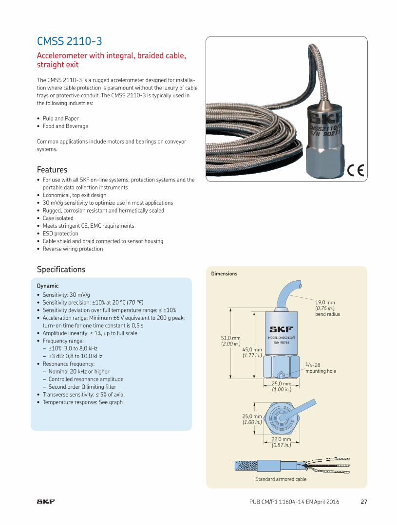
CMSS 2110-3Accelerometer with integral, braided cable, straight exit
The CMSS 2110-3 is a rugged accelerometer designed for installa-
tion where cable protection is paramount without the luxury of cable
trays or protective conduit. The CMSS 2110-3 is typically used in
the following industries:
• Pulp and Paper
• Food and Beverage
Common applications include motors and bearings on conveyor
systems.
Features• For use with all SKF on-line systems, protection systems and the
portable data collection instruments
• Economical, top exit design
• 30 mV/g sensitivity to optimize use in most applications
• Rugged, corrosion resistant and hermetically sealed
• Case isolated
• Meets stringent CE, EMC requirements
• ESD protection
• Cable shield and braid connected to sensor housing
• Reverse wiring protection
Specifications
Dynamic
• Sensitivity: 30 mV/g
• Sensitivity precision: ±10% at 20 °C (70 °F)
• Sensitivity deviation over full temperature range: ≤ ±10%
• Acceleration range: Minimum ±6 V equivalent to 200 g peak;
turn-on time for one time constant is 0,5 s
• Amplitude linearity: ≤ 1%, up to full scale
• Frequency range:
– ±10%: 3,0 to 8,0 kHz
– ±3 dB: 0,8 to 10,0 kHz
• Resonance frequency:
– Nominal 20 kHz or higher
– Controlled resonance amplitude
– Second order Q limiting filter
• Transverse sensitivity: ≤ 5% of axial
• Temperature response: See graph
Dimensions
MODEL CMSS2110/3
S/N 98765
19,0 mm (0.75 in.) bend radius
51,0 mm (2.00 in.)
45,0 mm (1.77 in.)
1/4-28 mounting hole
25,0 mm (1.00 in.)
25,0 mm (1.00 in.)
22,0 mm (0.87 in.)
Standard armored cable
27PUB CM/P1 11604-14 EN April 2016
Electrical
• Power requirements:
– Voltage source: 24 V DC, ±20%
– Constant current diode: 2 to 6 mA
• Electrical noise:
– Broadband (2,0 to 20,0 kHz): < 0,7 mg RMS
• Output impedance: < 50 Ω
• Bias output voltage: 11,5 V DC (±10%) for 24 V DC supply voltage
over the temperature range from –50 to +100 °C (–60 to
+210 °F)
• Grounding:
– Case isolated, internally shielded (Faraday cage)
– The internal Faraday cage is connected to the signal return of
the shielded twisted pair
– The internal shield, as well as the stainless steel braid, is
connected to the sensor housing
• Isolation to sensor housing: > 10 MΩ over full temperature range
• Over-voltage protection
• Reverse polarity (wiring) protection
Environmental
• Temperature range: –50 to +120 °C (–60 to +250 °F) operating
temperature
• Vibration limit: 500 g peak
• Shock limit: 1 000 g peak
• Electromagnetic sensitivity, equivalent g, maximum:
< 100 µg/gauss at 50 to 60 Hz
• Base strain sensitivity: 200 µg/µstrain
• CE: According to the generic immunity standard for Industrial
Environment EN 50082-2
– Acceptance criteria: The generated “false equivalent g level”
under the above test conditions should be less than 2 mg
measured peak to peak
Physical
• Dimensions: See drawing
• Cable length: 5 m (16.4 ft.)
• Weight: 350 g (12.3 oz.), including cable
• Case material: 316L stainless steel
• Mounting: 1/4-28 to M8 and 1/4-28 to 1/4-28 mounting studs
provided
• Mounting torque: 2,9 Nm (24 in- lbs.)
• Connections:
– Integral cable
– Power/Signal: White
– Common: Black
– Shielding: Drain
• Cable:
– Integral cable, 5 m (16.4 ft.) long
– Shielded twisted pair; two times AWG 20
– Shield grounded to sensor housing
– Cable armored with stainless steel braid
– Braid also connected to sensor housing
– High temperature cable
– Cable diameter less than 5 mm (0.19 in.)
• Cable specifications: 2/C 20 AWG FEP/A/M/FEP 10-1254
• Cable capacitance: 25 pF/m (80 pF/ft.)
Typical temperature response
Temperature, °C (°F)
Deviation, % sensitivity
+10
+5
0
–5
–10
–50 0 +50 +100 +120
(–60) (+30) (+120) (+210) (+250)
Typical frequency response
Frequency, Hz
Deviation, dB
+20
0
–20 1 10 100 1k 10k 100k
+10
–10
Ordering information
CMSS 2110-3 Accelerometer, 30mV/g, with 5 meter (16,4 ft) ntegral braided cable, straight exit.
CMSS 2110-3-50 Accelerometer, 30mV/g, with 15 meter (50 ft) integral braided cable, straight exit.
CMSS 2110-3-XX (ft) Accelerometer, 30mV/g, with custom integral braided cable, straight exit
• 1/4-28 and M8 mounting studs provided. Calibration sensitivity is provided for each accelerometer package with nominal sensitivity etched on each unit.
28 PUB CM/P1 11604-14 EN April 2016

CMPT 2310Accelerometer for mining industry, integral, braided cable, side exit
The CMPT 2310 is a physically rugged accelerometer optimized for
use in heavy-duty environments in the following industries:
• Mining
• Mineral Processing
• Cement
In these industries, dust, mud and flying debris are commonplace,
together with low rotational speeds. When used on shakers and
screens, the accelerometer must also withstand high levels of con-
tinuous and random vibration. The sensor uses an integral cable
with stainless over-braid for mounting where protective conduit is
not available.
Features• For use with the SKF on-line system IMx-S, IMx-M, MCT and CTU
• 100 mV/g sensitivity
• Physically rugged
• Meets CE, EMC requirements
• Low profile, side exit industrial accelerometer with M6 × 1 and 1/4-28 UNF socket head cap screws provided
• 5 m (16.4 ft.) integral cable with stainless steel over-braid
• Corrosion resistant and hermetically sealed
• The internal sensor capsule is isolated from the machine ground
• Low noise, highly shock resistant
• Overload protected electronics
Dimensions
CMPT2310S/N 00000
21,0 mm (0.83 in.)
34,0 mm (1.34 in.)
29,0 mm (1.14 in.)
ø 4,4 mm (0.17 in.)
47,2 mm (1.86 in.)
11,0 mm (0.43 in.)
14,0 mm (0.55 in.)
ACCEL signal / supply WHITE
ACCEL/TEMP GND (common) BLACK
TEMP signal high RED (CMPT 2310T only)
GND wire
SpecificationsSpecifications conform to ISA-RP-37.2 (1-95) and are typical values
referenced at 24 °C (75 °F), 24 V DC supply, 4 mA constant current
and 80 Hz.
Dynamic
• Sensitivity: 100 mV/g
• Sensitivity precision: ±10%
• Sensitivity deviation over full temperature range: 10%, approxi-
mately –5% at –50 °C (–60 °F) and +5% at +120 °C (+250 °F)
• Acceleration range: 70 g
• Amplitude linearity: < 1%, up to full scale
• Frequency range: 1 Hz to 10 kHz
• Transverse sensitivity: ≤ 5% of axial
29PUB CM/P1 11604-14 EN April 2016

Electrical
• Power requirements:
– Voltage source: 24 V DC nominal, 18 to 30 V DC
– Constant current diode: 4 mA at 24 V, 2 to 10 mA is permissible
• Electrical noise: < 1 mg RMS broadband 2,5 Hz to 25,0 kHz
• Bias output voltage: 11,5 V DC, ±10% for 24 V DC supply at
25 °C (75°F)
• Grounding: Case isolated, internally shielded (Faraday cage)
– Faraday cage connected to power supply return
• Over-voltage protection: Approximately 18 V DC
• Reverse polarity (wiring) protection installed
Environmental
• Temperature range:
– Accelerometer measurement temperature range:
–50 to +120 °C (–60 to +250 °F)
– Maximum operating temperature: 120 °C (250 °F)
– Storage temperature: –50 to +150 °C (–60 to +300 °F)
• Vibration limit: 70 g peak
• Shock limit: 5 000 g peak
• Electromagnetic sensitivity, equivalent g, maximum:
< 100 µg/gauss at 50 to 60 Hz
• CE: According to the generic immunity standard for Industrial
Environment EN 50082-2
– Acceptance criteria: The generated “false equivalent g level”
under the above test conditions should be less than 2 mg
measured peak to peak
• IEC: 529, IP 67
Physical
• Dimensions: See drawing
• Weight:
– Sensor without cable: 210 g (7.4 oz.)
– Sensor with cable: 410 g (14.5 oz.)
• Case material: 304 stainless steel
• Mounting: M6 × 1 and 1/4-28 UNF socket head cap screws
included
• Mounting torque: 6 Nm (50 in. lbs.)
• Cable: Integral cable, 5 m (16.4 ft.) length
• Wire specification: 0,32 mm² (AWG 22) stranded tin copper
(seven strands at 0,05 mm² each)
• Connections:
– White: ACCEL signal/power (connected to constant current
source)
– Black: ACCEL signal ground (GND)
– Blank twisted wire: Screen connected to internal shield
Ordering information
CMSS 2310 Copperhead accelerometer for mining industry with 5 meter (16,4 ft) integral braided cable, side exit.
CMSS 2310x10 Copperhead accelerometer for mining industry with 10 meter (33 ft) integral braided cable, side exit.
CMSS 2310x15 Copperhead accelerometer for mining industry with 15 meter (50 ft) integral braided cable, side exit.
• 1/4-28 and M6 × 1 socket head cap screws provided. Calibration sensitivity is provided for each accelerometer package with nominal sensitivity etched on each unit.
30 PUB CM/P1 11604-14 EN April 2016

CMPT 2323Accelerometer for mining industry, integral, braided cable, side exit
The CMPT 2323 is a physically rugged accelerometer optimized for
use in heavy-duty environments in the following industries:
• Mining
• Mineral Processing
• Cement
In these industries, dust, mud and flying debris are commonplace,
together with low rotational speeds. When used on shakers and
screens, the accelerometer must also withstand high levels of con-
tinuous and random vibration. The sensor uses an integral cable
with stainless over-braid for mounting where protective conduit is
not available.
A higher sensitivity is used for detection of low amplitude signals
in slow moving equipment.
Features• For use with the SKF on-line system IMx-S, IMx-M, MCT and CTU
• 230 mV/g sensitivity
• Physically rugged
• Meets CE, EMC requirements
• Low profile, side exit industrial accelerometer with M6 × 1 and 1/4-28 UNF socket head cap screws provided
• 5 m (16.4 ft.) integral cable with stainless steel over-braid
• Corrosion resistant and hermetically sealed
• The internal sensor capsule is isolated from the machine ground
• Low noise, highly shock resistant
• Overload protected electronics
Dimensions
CMPT2323S/N 00000
21,0 mm (0.83 in.)
34,0 mm (1.34 in.)
29,0 mm (1.14 in.)
ø 4,4 mm (0.17 in.)
47,2 mm (1.86 in.)
11,0 mm (0.43 in.)
14,0 mm (0.55 in.)
ACCEL signal / supply WHITE
ACCEL/TEMP GND (common) BLACK
TEMP signal high RED (CMPT 2323T only)
GND wire
SpecificationsSpecifications conform to ISA-RP-37.2 (1-95) and are typical values
referenced at 24 °C (75 °F), 24 V DC supply, 4 mA constant current
and 80 Hz.
Dynamic
• Sensitivity: 230 mV/g
• Sensitivity precision: ±10%
• Sensitivity deviation over full temperature range: 10%, approxi-
mately –5% at –50 °C (–60 °F) and +5% at +120 °C (+250 °F)
• Acceleration range: 70 g
• Amplitude linearity: < 1%, up to full scale
• Frequency range: 0,2 Hz to 10 kHz
• Transverse sensitivity: ≤ 5% of axial
31PUB CM/P1 11604-14 EN April 2016

Electrical
• Power requirements:
– Voltage source: 24 V DC nominal, 18 to 30 V DC
– Constant current diode: 4 mA at 24 V, 2 to 10 mA is permissible
• Electrical noise: < 1 mg RMS broadband 2,5 Hz to 25,0 kHz
• Bias output voltage: 11,5 V DC, ±10% for 24 V DC supply at
25 °C (75 °F)
• Grounding: Case isolated, internally shielded (Faraday cage)
– Faraday cage connected to power supply return
• Over-voltage protection: Approximately 18 V DC
• Reverse polarity (wiring) protection installed
Environmental
• Temperature range:
– Accelerometer measurement temperature range:
–50 to +120 °C (–60 to +250 °F)
– Maximum operating temperature: 120 °C (250 °F)
– Storage temperature: –50 to +150 °C (–60 to +300 °F)
• Vibration limit: 70 g peak
• Shock limit: 5 000 g peak
• Electromagnetic sensitivity, equivalent g, maximum:
< 100 µg/gauss at 50 to 60 Hz
• CE: According to the generic immunity standard for Industrial
Environment EN 50082-2
– Acceptance criteria: The generated “false equivalent g level”
under the above test conditions should be less than 2 mg
measured peak to peak
• IEC: 529, IP 67
Physical
• Dimensions: See drawing
• Weight:
– Sensor without cable: 210 g (7.4 oz.)
– Sensor with cable: 410 g (14.5 oz.)
• Case material: 304 stainless steel
• Mounting: M6 × 1 and 1/4-28 UNF socket head cap screws
provided
• Mounting torque: 6 Nm (50 in. lbs.)
• Cable: Integral cable, 5 m (16.4 ft.) length
• Wire specification: 0,32 mm² (AWG 22) stranded tin copper
(7 strands at 0,05 mm² each)
• Connections:
– White: ACCEL signal/power (connected to constant current
source)
– Black: ACCEL signal ground (GND)
– Blank twisted wire: Screen connected to internal shield
Ordering information
CMPT 2323 Copperhead accelerometer for mining industry, 230 mV/g, with 5 meter (16,4 ft) integral braided cable, side exit.
CMSS 2323x10 Copperhead accelerometer for mining industry, 230 mV/g, with 10 meter (33 ft) integral braided cable, side exit.
CMSS 2323x15 Copperhead accelerometer for mining industry, 230 mV/g, with 15 meter (50 ft) integral braided cable, side exit.
• 1/4-28 and M6 × 1 socket head cap screws provided. Calibration sensitivity is provided for each accelerometer package with nominal sensitivity etched on each unit.
32 PUB CM/P1 11604-14 EN April 2016

CMSS-WIND-100-10Small accelerometer for wind turbines, with integral cable, side exit
The CMSS WIND-100-10 is an accelerometer optimized for use
with wind turbine applications:
• Wind turbine gearboxes
• Wind turbine generators
The small-size accelerometer is specially configured for unobtrusive
mounting on wind turbine drive components, within the relatively
protected environment of the turbine’s nacelle. An integral cable is
used to eliminate any cause to travel to a remote site to fix a loose
connector.
Features• For use with the SKF on-line system IMx-W
• 100 mV/g sensitivity
• Meets CE, EMC requirements
• High resistance to electrical noise
• Low profile integral cable accelerometer
• Compact design ideal for mounting with limited space
• Corrosion resistant
Dimensions
40,1 mm (1.58 in.)
15,9 mm (0.63 in.)
24,6 mm (0.97 in.)
White: Signal/Power
Black: Ground
Molded integral cable terminating in blunt cut 10 m (32 ft.) from application
14,0 mm (0.56 in.) hex
1/2-20 UNF-2A
M6 X 1.00-6g
Mounting stud model M080A159 (supplied)
4 mm hex allen key required
SpecificationsSpecifications based on low-profile industrial constant current
accelerometer, 100 mV/g, 0,5 to 10 000 Hz, side exit, 10 m (32 ft.)
integral cable and swiveled base.
Dynamic
• Sensitivity: 100 mV/g
• Sensitivity precision: ±10%
• Acceleration range: ±490 m/s2 (±50 g)
• Amplitude linearity: ±1%
• Frequency range: 0,5 Hz to 10 kHz (30 to 600 000 cpm)
• Resonance frequency, mounted, nominal: 25 kHz (1 500 kcpm)
• Transverse sensitivity: ≤ 7%
• Temperature response:See graph
33PUB CM/P1 11604-14 EN April 2016

Ordering information
CMSS WIND-100-10 Small accelerometer for wind turbines with integral cable, side exit, 10 m (32.8 ft.).CMSS WIND-100-15 Small accelerometer for wind turbines with integral cable, side exit, 15 m (49.2 ft.).
Electrical
• Power requirements:
– Voltage source: 18 to 28 V DC
– Constant current diode: 2 to 20 mA
• Electrical noise:
– Spectral:
· Output impedance: < 150 Ω
• Bias output voltage: 8 to 12 V DC
• Electrical isolation (case): > 108 Ω
Environmental
• Temperature range: –55 to +120 °C (–65 to +250 °F)
• Shock limit: 5 000 g peak
• Sealing: Welded hermetic
• CE: According to the generic immunity standard for Industrial
Environment EN 50082-2
– Acceptance criteria: The generated “false equivalent g level”
under the above test conditions should be less than 2 mg
measured peak to peak
Physical
• Dimensions: See drawing
• Weight: 31 g (1.1 oz.)
• Case material: Stainless steel
• Enclosure rating: IP 68
• Sensing element: Ceramic, shear
• Mounting: Threaded stud M6 x 1 male
• Mounting torque:
– Stud: 9,5 to 10,8 Nm (7 to 8 ft. lbs.)
– Hex nut: 2,7 to 6,8 Nm (2 to 5 ft. lbs.)
• Connection: Molded integral cable, side
• Cable type: steel over braided FEP
Typical frequency response
Frequency, Hz
Deviation, dB
3
2
1
0
–1
–2
–30.5 1 10 100 1 k 10 k
Typical temperature response
Temperature, °C (°F)
Deviation, % sensitivity+20
+10
0
–10
–20
–54 0 +50 +100 +121
(–65) (+30) (+120) (+210) (+250)
34 PUB CM/P1 11604-14 EN April 2016
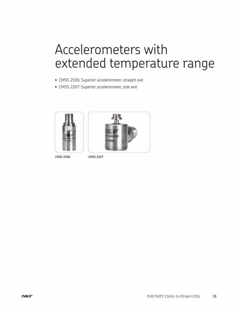
Accelerometers with extended temperature range• CMSS 2106 Superior accelerometer, straight exit
• CMSS 2207 Superior accelerometer, side exit
CMSS 2106 CMSS 2207
35PUB CM/P1 11604-14 EN April 2016

The CMSS 2106 accelerometer is a multi-purpose sensor with an
elevated temperature resistance to extend life and performance in
applications that are known to provide a challenging hot environ-
ment. The sensor is most commonly deployed in the following
industries:
• Pulp and Paper – dryer sections
• Mineral Processing – ovens and kilns
• Metalworking – hot rolling mills
Features• Optimal for use with SKF on-line system IMx-S and all portable
data collection instruments
• Rugged, economical and all around high temperature, general
purpose sensor for up to 150 °C (300 °F) operating temperature
• 100 mV/g sensitivity to optimize use in multiple applications
• Exceptional bias voltage (BV) stability at elevated temperatures
• Designed for exceptional low noise level over a wide temperature
range
• Meets stringent CE, EMC requirements
• Two mounting studs (1/4-28 and M8 × 1,25) provided
• Corrosion resistant and hermetically sealed for installation in high
humidity areas
• Reverse polarity wiring protection
Recommended connector/cable assembly
• CMSS 932 series
SpecificationsSpecifications conform to ISA-RP-37.2 (1-64) and are typical values
referenced at 24 °C (75 °F), 24 V DC supply, 4 mA constant current
and 100 Hz.
Dynamic
• Sensitivity: 100 mV/g
• Sensitivity precision: ±10% at –50 to +150 °C (–60 to +300 °F)
• Acceleration range: 50 g peak
• Amplitude linearity: 1%
• Frequency range:
– ±5%: 4,0 to 4 000 Hz
– ±10%: 3,0 to 6 000 Hz
– ±3 dB: 1,0 to 10 000 Hz
• Resonance frequency, mounted, nominal: 20 kHz
• Transverse sensitivity: ≤ 5% of axial
• Temperature response: See graph
CMSS 2106Superior accelerometer, straight exit
Dimensions
MODEL CMSS2106
S/N S00000
25,0 mm (0.98 in.)
23,8 mm (0.94 in.)
1/4-28 mounting hole
15/16 in. hex
Two pin connector MIL-C-5015
61,0 mm (2.42 in.)
45,0 mm (1.78 in.)
Limited
Lifetime
WARRANTY
Electrical
• Power requirements:
– Voltage source: 24 V DC nominal, 18 to 30 V DC
– Constant current diode: 2 to 4 mA, recommended 4 mA
• Electrical noise:
– 2,0 Hz: 30 µg/√Hz
• Output impedance: < 100 Ω
• Bias output voltage:
– 12 V DC at 25 °C (75 °F)
– 11 V DC at 150 °C (300 °F)
• Grounding: Case isolated, internally shielded
36 PUB CM/P1 11604-14 EN April 2016

Environmental
• Temperature range: –50 to +150 °C (–60 to +300 °F) operating
temperature
• Vibration limit: 500 g peak
• Shock limit: 2 500 g peak
• Electromagnetic sensitivity, equivalent g, maximum: 15 µg/gauss
• Sealing: Hermetic
• Base strain sensitivity: 500 µg/µstrain
• CE: According to the generic immunity standard for Industrial
Environment EN 50082-2
– Acceptance criteria: The generated “false equivalent g level”
under the above test conditions should be less than 2 mg
measured peak to peak
Physical
• Dimensions: See drawing
• Weight: 135 g (4.8 oz.)
• Case material: 316L stainless steel
• Mounting:
– Internal 1/4-28 thread
– M8 × 1,25 and 1/4-28 to 1/4-28 mounting studs provided
• Mounting torque: 2,9 Nm (24 in. lbs.)
• Connections:
– Pin A: Signal/Power
– Pin B: Common
• Mating connector: CMSS 932-68LC or CMSS 932-68TL, two pin,
IP 68, locking collar or twist lock
• Recommended cable: CMSS 932-SY-XXM and
CMSS 932-DY-XXM, two conductor, twisted pair, single or double
shielded, yellow
Ordering information
CMSS 2106 Superior accelerometer, straight exit with MIL-C-5015 two pin connector.• 1/4-28 and M8 mounting studs provided. Calibration sensitivity is
provided for each accelerometer package with nominal sensitivity etched on each unit.
Typical temperature response
Temperature, °C (°F)
Deviation, % sensitivity
+10
+5
0
–5
–10
–50 0 +50 +100 +150
(–60) (+30) (+120) (+210) (+300)
Typical frequency response
Frequency, Hz
Deviation, dB
3
2
1
0
–1
–2
–31 10 100 1 k 10 k
37PUB CM/P1 11604-14 EN April 2016

CMSS 2207Superior accelerometer, side exit
The CMSS 2207 accelerometer is a multi-purpose sensor with an
elevated temperature resistance to extend life and performance in
applications that are known to provide a challenging hot environ-
ment. The sensor is most commonly deployed in the following
industries:
• Pulp and Paper – dryer sections
• Mineral Processing – ovens and kilns
• Metalworking – hot rolling mills
Features• Optimal for use with SKF on-line system IMx-S and all portable
data collection instruments
• Rugged, economical and all around high temperature, general
purpose sensor for up to 150 °C (300 °F) operating temperature
• 100 mV/g sensitivity to optimize use in multiple applications
• Exceptional bias voltage (BV) stability at elevated temperatures
• Designed for exceptional low noise level over a wide temperature
range
• Meets stringent CE, EMC requirements
• Captive mounting bolts (1/4-28 or M6 × 1,0) provided
• Corrosion resistant and hermetically sealed for installation in high
humidity areas
• Reverse polarity wiring protection
Recommended connector/cable assembly
• CMSS 932 series
SpecificationsSpecifications conform to ISA-RP-37.2 (1-64) and are typical values
referenced at 24 °C (75 °F), 24 V DC supply, 4 mA constant current
and 100 Hz.
Dynamic
• Sensitivity: 100 mV/g
• Sensitivity precision: ±10% at 25 °C (75 °F)
• Acceleration range: 50 g peak
• Amplitude linearity: ≤ 1%, up to full scale
• Frequency range:
– ±5%: 4,0 to 5 000 Hz
– ±10%: 3,0 to 7 000 Hz
– ±3 dB: 1,0 to 11 000 Hz
• Resonance frequency, mounted, nominal: 20 kHz
• Transverse sensitivity, maximum: ≤ 5% of axial
• Temperature response: See graph
Dimensions
A B
MODEL CMSS2207
S/N S00000
1/4-28 mounting
thread
30,0 mm (1.20 in.)
43,0 mm (1.70 in.)
26,0 mm (1.05 in.)
54,0 mm (2.15 in.)
6,0 mm (0.25 in.)
Side View
Top View
Bottom View End View
Safety wire hole 1,5 mm (0.06 in.) diameter
Two pin connector MIL-C-5015
Limited
Lifetime
WARRANTY
Electrical
• Power requirements:
– Voltage source: 24 V DC nominal, 18 to 30 V DC
– Constant current diode: 2 to 4 mA, recommended 4 mA
• Electrical noise:
– 2,0 Hz: 30 µg/√Hz
• Output impedance: < 100 Ω
• Bias output voltage:
– 12 V DC at 25 °C (75 °F)
– 11 V DC at 150 °C (300 °F)
• Grounding: Case isolated, internally shielded
38 PUB CM/P1 11604-14 EN April 2016

Environmental
• Temperature range: –50 to +150 °C (–60 to +300 °F) operating
temperature
• Vibration limit: 500 g peak
• Shock limit: 2 500 g peak
• Electromagnetic sensitivity, equivalent g, maximum: < 5 µg/gauss
• Base strain sensitivity: 100 µg/µstrain
• CE: According to the generic immunity standard for Industrial
Environment EN 50082-2
– Acceptance criteria: The generated “false equivalent g level”
under the above test conditions should be less than 2 mg
measured peak to peak
Physical
• Dimensions: See drawing
• Weight: 145 g (5.1 oz.)
• Case material: 316L stainless steel
• Mounting: M6 × 1,0 and 1/4-28 captive mounting bolts provided
• Mounting torque: 3,4 Nm (30 in. lbs.)
• Connections:
– Pin A: Signal/Power
– Pin B: Common
• Mating connector: CMSS 932-68LC or CMSS 932-68TL, two pin,
IP 68, locking collar or twist lock
• Recommended cable: CMSS 932-SY-XXM and
CMSS 932-DY-XXM, two conductor, twisted pair, single or double
shielded, yellow
Ordering information
CMSS 2207 Superior accelerometer, side exit with MIL-C-5015 two pin connector.• 1/4-28 and M6 mounting studs provided. Calibration sensitivity is
provided for each accelerometer package with nominal sensitivity etched on each unit.
Typical temperature response
Temperature, °C (°F)
Deviation, % sensitivity
+10
+5
0
–5
–10
–50 0 +50 +100 +150
(–60) (+30) (+120) (+210) (+300)
Typical frequency response
Frequency, Hz
Deviation, dB
3
2
1
0
–1
–2
–31 10 100 1 k 10 k
39PUB CM/P1 11604-14 EN April 2016

Combination vibration and temperature sensors• CMSS 2100T Industrial sensor, straight exit, acceleration and temperature
• CMSS 2200T Industrial sensor, side exit, acceleration and temperature
• CMSS 793T-3 Superior sensor, straight exit, acceleration and temperature
• CMSS 797T-1 Superior sensor, ring mode, side exit, acceleration and temperature
• CMPT 2310T Sensor for mining industry, side exit, acceleration and temperature
• CMPT 2323T Sensor for mining industry, side exit, acceleration and temperature
CMSS 2100T CMSS 2200T CMSS 793T-3
CMSS 797T-1 CMPT 2310T CMPT 2323T
40 PUB CM/P1 11604-14 EN April 2016
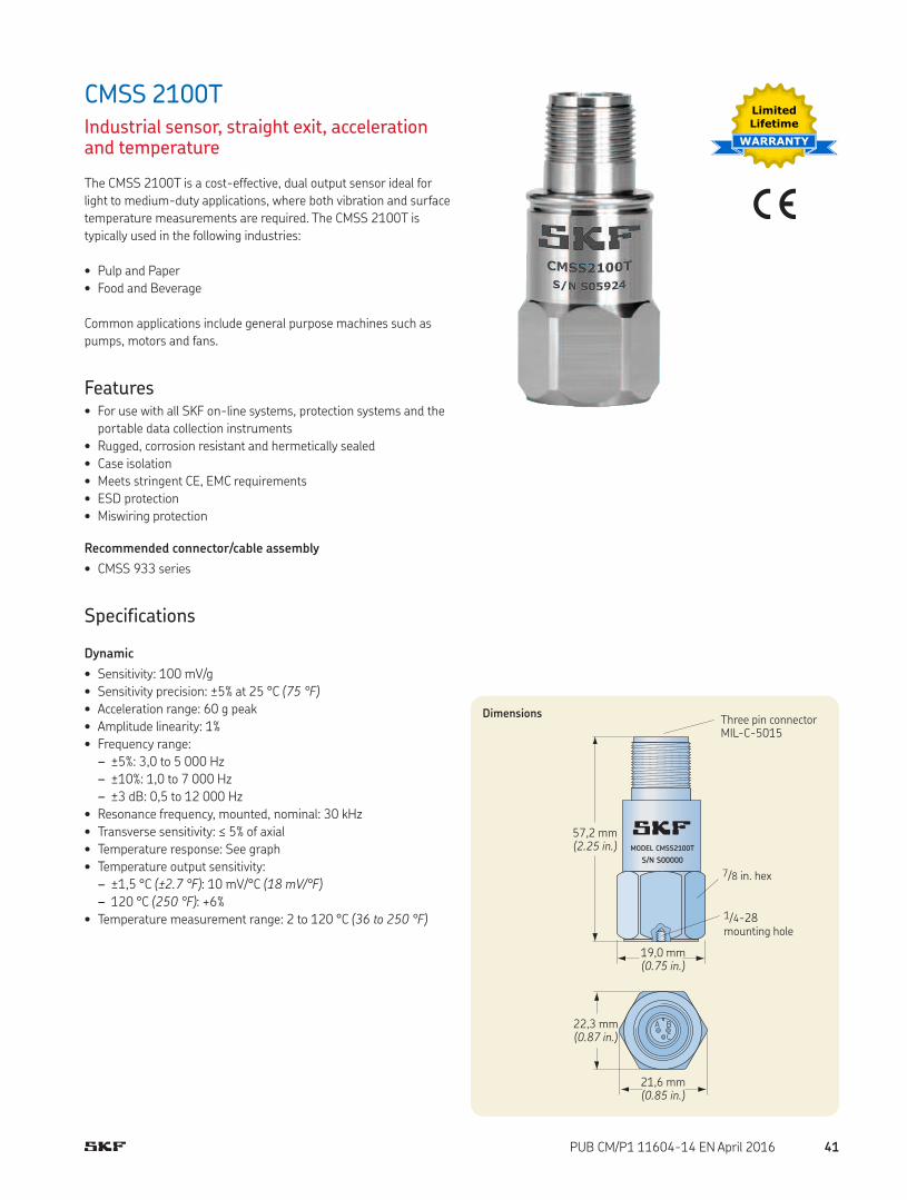
CMSS 2100TIndustrial sensor, straight exit, acceleration and temperature
The CMSS 2100T is a cost-effective, dual output sensor ideal for
light to medium-duty applications, where both vibration and surface
temperature measurements are required. The CMSS 2100T is
typically used in the following industries:
• Pulp and Paper
• Food and Beverage
Common applications include general purpose machines such as
pumps, motors and fans.
Features• For use with all SKF on-line systems, protection systems and the
portable data collection instruments
• Rugged, corrosion resistant and hermetically sealed
• Case isolation
• Meets stringent CE, EMC requirements
• ESD protection
• Miswiring protection
Recommended connector/cable assembly
• CMSS 933 series
Specifications
Dynamic
• Sensitivity: 100 mV/g
• Sensitivity precision: ±5% at 25 °C (75 °F)
• Acceleration range: 60 g peak
• Amplitude linearity: 1%
• Frequency range:
– ±5%: 3,0 to 5 000 Hz
– ±10%: 1,0 to 7 000 Hz
– ±3 dB: 0,5 to 12 000 Hz
• Resonance frequency, mounted, nominal: 30 kHz
• Transverse sensitivity: ≤ 5% of axial
• Temperature response: See graph
• Temperature output sensitivity:
– ±1,5 °C (±2.7 °F): 10 mV/°C (18 mV/°F)
– 120 °C (250 °F): +6%
• Temperature measurement range: 2 to 120 °C (36 to 250 °F)
Dimensions
MODEL CMSS2100T
S/N S00000
A B
C
21,6 mm (0.85 in.)
22,3 mm (0.87 in.)
57,2 mm (2.25 in.)
19,0 mm (0.75 in.)
Three pin connector MIL-C-5015
7/8 in. hex
1/4-28 mounting hole
Limited
Lifetime
WARRANTY
41PUB CM/P1 11604-14 EN April 2016
Electrical
• Power requirements:
– Voltage source: 18 to 30 V DC
– Constant current diode: 2 to 10 mA
• Electrical noise:
– Broadband:
· 2,5 Hz to 25 kHz: 700 µg
– Spectral:
· 10 Hz: 10 µg/√Hz
· 100 Hz: 5 µg/√Hz
· 1 000 Hz: 5 µg/√Hz
• Output impedance: < 100 Ω
• Bias output voltage: 10 V DC
• Grounding: Case isolated, internally shielded
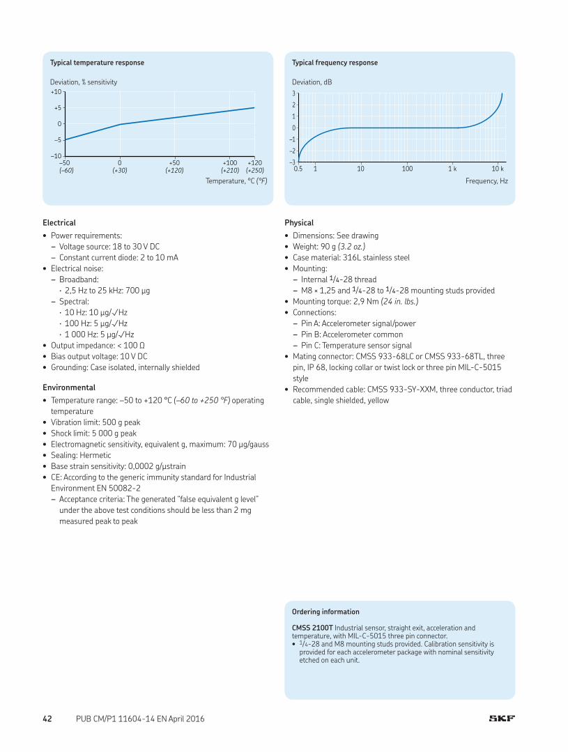
Environmental
• Temperature range: –50 to +120 °C (–60 to +250 °F) operating
temperature
• Vibration limit: 500 g peak
• Shock limit: 5 000 g peak
• Electromagnetic sensitivity, equivalent g, maximum: 70 µg/gauss
• Sealing: Hermetic
• Base strain sensitivity: 0,0002 g/µstrain
• CE: According to the generic immunity standard for Industrial
Environment EN 50082-2
– Acceptance criteria: The generated “false equivalent g level”
under the above test conditions should be less than 2 mg
measured peak to peak
Physical
• Dimensions: See drawing
• Weight: 90 g (3.2 oz.)
• Case material: 316L stainless steel
• Mounting:
– Internal 1/4-28 thread
– M8 × 1,25 and 1/4-28 to 1/4-28 mounting studs provided
• Mounting torque: 2,9 Nm (24 in. lbs.)
• Connections:
– Pin A: Accelerometer signal/power
– Pin B: Accelerometer common
– Pin C: Temperature sensor signal
• Mating connector: CMSS 933-68LC or CMSS 933-68TL, three
pin, IP 68, locking collar or twist lock or three pin MIL-C-5015
style
• Recommended cable: CMSS 933-SY-XXM, three conductor, triad
cable, single shielded, yellow
Ordering information
CMSS 2100T Industrial sensor, straight exit, acceleration and temperature, with MIL-C-5015 three pin connector.• 1/4-28 and M8 mounting studs provided. Calibration sensitivity is
provided for each accelerometer package with nominal sensitivity etched on each unit.
Typical temperature response
Temperature, °C (°F)
Deviation, % sensitivity+10
+5
0
–5
–10
–50 0 +50 +100 +120
(–60) (+30) (+120) (+210) (+250)
Typical frequency response
Frequency, Hz
Deviation, dB
3
2
1
0
–1
–2
–30.5 1 10 100 1 k 10 k
42 PUB CM/P1 11604-14 EN April 2016

The CMSS 2200T is a cost-effective, dual output sensor ideal for
light to medium-duty applications, where both vibration and
temperature measurements are required. The CMSS 2200T is
typically used in the following industries:
• Pulp and Paper
• Food and Beverage
Common applications include general purpose machines such as
pumps, motors and fans.
Features• For use with SKF on-line systems and protection systems (note
that DMx requires adapter module CMMA 9700); recommended
sensor for the WMx
• Measures both acceleration and temperature
• Low profile
• Rugged, corrosion resistant and hermetically sealed for installa-
tion in high humidity areas
• 100 mV/g sensitivity to optimize use in multiple applications
• 10 mV/°C temperature output sensitivity
• CE approved, meets EMC requirements
• ESD protection
• M6 and 1/4-28 captive mounting bolts provided
• Reverse wiring protection
Recommended connector/cable assembly
• CMSS 933 series, three pin connector, IP 68 locking, collar or
twist lock
Specifications
Dynamic
• Sensitivity: 100 mV/g
• Sensitivity precision: ±5% at 25 °C (75 °F)
• Acceleration range: 60 g peak
• Amplitude linearity: 1%
• Frequency range:
– ±5%: 1,0 to 5 000 Hz
– ±10%: 0,7 to 10 000 Hz
– ±3 dB: 0,5 to 12 000 Hz
• Resonance frequency, mounted, minimum: 22 kHz
• Transverse sensitivity: ≤ 5% of axial
• Temperature response: See graph
• Temperature output sensitivity:
– ±1,5 °C (±2.7 °F): 10 mV/°C (18 mV/°F)
• Temperature measurement range: 2 to 120 °C (36 to 250 °F)
CMSS 2200TIndustrial sensor, side exit, acceleration and temperature
MODEL CMSS2200TS/N S0000
C A
B
Dimensions
Three pin connector MIL-C-5015
1/4-28 or M6 mounting screw
53,1 mm (2.09 in.)
37,0 mm (1.44 in.)
24,9 mm (0.98 in.)
30,2 mm (1.19 in.)
26,0 mm (1.04 in.)
23,0 mm (0.92 in.)
5,3 mm (0.21 in.)
Limited
Lifetime
WARRANTY
43PUB CM/P1 11604-14 EN April 2016
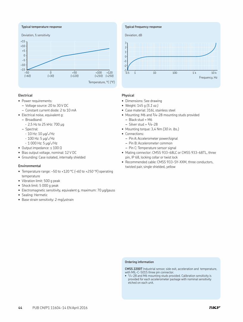
Electrical
• Power requirements:
– Voltage source: 20 to 30 V DC
– Constant current diode: 2 to 10 mA
• Electrical noise, equivalent g:
– Broadband:
· 2,5 Hz to 25 kHz: 700 µg
– Spectral:
· 10 Hz: 10 µg/√Hz
· 100 Hz: 5 µg/√Hz
· 1 000 Hz: 5 µg/√Hz
• Output impedance: ≤ 100 Ω
• Bias output voltage, nominal: 12 V DC
• Grounding: Case isolated, internally shielded
Environmental
• Temperature range: –50 to +120 °C (–60 to +250 °F) operating
temperature
• Vibration limit: 500 g peak
• Shock limit: 5 000 g peak
• Electromagnetic sensitivity, equivalent g, maximum: 70 µg/gauss
• Sealing: Hermetic
• Base strain sensitivity: 2 mg/µstrain
Physical
• Dimensions: See drawing
• Weight: 145 g (5.1 oz.)
• Case material: 316L stainless steel
• Mounting: M6 and 1/4-28 mounting studs provided
– Black stud = M6
– Silver stud = 1/4-28
• Mounting torque: 3,4 Nm (30 in. lbs.)
• Connections:
– Pin A: Accelerometer power/signal
– Pin B: Accelerometer common
– Pin C: Temperature sensor signal
• Mating connector: CMSS 933-68LC or CMSS 933-68TL, three
pin, IP 68, locking collar or twist lock
• Recommended cable: CMSS 933-SY-XXM, three conductors,
twisted pair, single shielded, yellow
Ordering information
CMSS 2200T Industrial sensor, side exit, acceleration and temperature, with MIL-C-5015 three pin connector.• 1/4-28 and M6 mounting studs provided. Calibration sensitivity is
provided for each accelerometer package with nominal sensitivity etched on each unit.
Typical frequency response
Frequency, Hz
Deviation, dB
3
2
1
0
–1
–2
–30.5 1 10 100 1 k 10 k
Typical temperature response
Temperature, °C (°F)
Deviation, % sensitivity
+15
+10
+5
0
–5
–10
–15
–50 0 +50 +100 +120
(–60) (+30) (+120) (+210) (+250)
44 PUB CM/P1 11604-14 EN April 2016

CMSS 793T-3Superior sensor, straight exit, acceleration and temperature
The CMSS 793T-3 is a higher precision accelerometer that also
offers an in-built measurement of the temperature of the mounting
point surface. The sensor is most applicable in the following
industries:
• Power Generation (Fossil, Nuclear, Hydro) – pumps and fans,
where regulatory expectations may require a higher vibration
precision
The surface temperature measurement is good for rolling element
(anti-friction) bearing housings and small journal bearing housings.
Temperature measurements in large journal bearings should use
established measurement locations.
Features• Optimal for use with the SKF on-line system DMx, IMx-S, IMx-M
and all portable data collection instruments
• Measures both temperature and acceleration
• Rugged construction
• Hermetically sealed
• Case isolated
• Meets stringent CE, EMC requirements
• ESD protection
• Miswiring protection
Recommended connector/cable assembly
• CMSS 933 series
Specifications
Dynamic
• Sensitivity: 100 mV/g
• Sensitivity precision: ±5% at 25 °C (75 °F)
• Peak amplitude (24 V supply): 80 g
• Frequency range:
– ±5%: 1,5 to 5 000 Hz
– ±10%: 1,0 to 7 000 Hz
– ±3 dB: 0,5 to 15 000 Hz
• Resonance frequency, mounted, nominal: 24 kHz
• Transverse sensitivity: ≤ 5% of axial
• Temperature response: See graph
• Temperature output sensitivity: ±5% of 10 mV/°K
• Temperature measurement range: –50 to +120 °C
(–60 to +250 °F)
Dimensions
MODEL CMSS793T-3
S/N S00000
25,4 mm (1.00 in.)
25,4 mm (1.00 in.)
25,4 mm (1.00 in.)
61,0 mm (2.42 in.)
45,0 mm (1.78 in.)
Three pin connector MIL-C-5015
15/16 in. hex
1/4-28 mounting hole
Electrical
Temperature sensor
• Power requirements:
– Voltage source: 18 to 30 V DC
– Constant current diode: 2 to 4 mA
• Grounding: Case isolated, internally shielded
Limited
Lifetime
WARRANTY
45PUB CM/P1 11604-14 EN April 2016

Environmental
• Temperature range: –50 to +120 °C (–60 to +250 °F)
• Vibration limit: 500 g peak
• Shock limit: 5 000 g peak
• Electromagnetic sensitivity, equivalent g, maximum: 10 µg/gauss
• Sealing: Hermetic
• Base strain sensitivity: 0,0005 g/µstrain
• CE: According to the generic immunity standard for Industrial
Environment EN 50082-2
– Acceptance criteria: The generated “false equivalent g level”
under the above test conditions should be less than 2 mg
measured peak to peak
Physical
• Dimensions: See drawing
• Weight: 115 g (4 oz.)
• Case material: 316L stainless steel
• Mounting: 1/4-28 tapped hole
• Mounting torque: 2,9 Nm (24 in. lbs.)
• Connections:
– Shell: Ground
– Pin A: Power and accelerometer signal
– Pin B: Accelerometer, temperature common
– Pin C: Power and temperature signal
• Mating connector: CMSS 933-68LC or CMSS 933-68TL, three
pin, IP 68, locking collar or twist lock
• Recommended cable: CMSS 933-SY-XXM, three conductor, triad
cable, single shielded, yellow
Accelerometer
• Power requirements:
– Voltage source: 18 to 30 V DC
– Constant current diode: 2 to 10 mA
• Electrical noise:
– Broadband:
· 2,5 Hz to 25 kHz: 600 µg
– Spectral:
· 10 Hz: 8 µg/√Hz
· 100 Hz: 5 µg/√Hz
· 1 000 Hz: 5 µg/√Hz
• Output impedance: < 100 Ω
• Bias output voltage: 12 V DC
• Grounding: Case isolated, internally shielded
Note: Each channel (acceleration and temperature) requires standard cur-rent powering for use with multiplexed sensors and data collector voltage inputs. Common leads are connected together inside the sensor.
Ordering information
CMSS 793T-3 Superior sensor, straight exit, acceleration and temperature, with MIL-C-5015 three pin connector.• 1/4-28 and M6 mounting studs provided. A calibration data certificate
with the actual sensitivity of the accelerometer is included in each package. The nominal sensitivity is etched on each unit.
Typical temperature response
Temperature, °C (°F)
Deviation, % sensitivity
+10
+5
0
–5
–10
–50 0 +50 +100 +120
(–60) (+30) (+120) (+210) (+250)
Block diagram
CX LM35 CZ
Piezofet AmplifierPin A Power and accelerometer signal
Pin C Power and temperature signal
Pin B Accelerometer return, temperature common
Typical frequency response
Frequency, Hz
Deviation, dB
3
2
1
0
–1
–2
–30.5 1 10 100 1 k 10 k
46 PUB CM/P1 11604-14 EN April 2016

CMSS 797T-1Superior sensor, ring mode, side exit, acceleration and temperature
The CMSS 797T-1 is a higher precision accelerometer that also
offers an in-built measurement of the temperature of the mounting
point surface. The sensor is most applicable in the following
industries:
• Power Generation (Fossil, Nuclear, Hydro) – pumps and fans,
where regulatory expectations may require a higher vibration
precision
The surface temperature measurement is good for rolling element
(anti-friction) bearing housings and small journal bearing housings.
Temperature measurements in large journal bearings should use
established measurement locations.
Features• Optimal for use with the SKF on-line system DMx, IMx-S, IMx-M
and all portable data collection instruments
• Measures both temperature and acceleration
• Rugged construction
• Hermetically sealed
• Case isolated
• Meets stringent CE, EMC requirements
• ESD protection
• Reverse wiring protection
Recommended connector/cable assembly
• CMSS 933 series
Specifications
Dynamic
• Sensitivity: 100 mV/g
• Sensitivity precision: ±5% at 25 °C (75 °F)
• Acceleration range: 80 g peak
• Amplitude non-linearity: 1%
• Frequency range:
– ±5%: 3,0 to 5 000 Hz
– ±10%: 2,0 to 7 000 Hz
– ±3 dB: 1,0 to 12 000 Hz
• Resonance frequency, mounted, nominal: 26 kHz
• Transverse sensitivity: ≤ 5% of axial
• Temperature response: See graph
• Temperature output sensitivity: ±5% of 10 mV/°K
• Temperature measurement range: –50 to +120 °C
(–60 to +250 °F)
Dimensions
MODEL CMSS797T-1
S/N S00000
54,0 mm (2.15 in.)
26,0 mm (1.05 in.)
1/4-28 mounting thread
Two pin connector MIL-C-5015
30,0 mm (1.20 in.)
43,0 mm (1.70 in.)
6,0 mm (0.25 in.)
Electrical
Accelerometer
• Power requirements:
– Voltage source: 18 to 30 V DC
– Constant current diode: 2 to 10 mA
• Electrical noise:
– Broadband:
· 2,5 Hz to 25 kHz: 600 µg
– Spectral:
· 10 Hz: 8 µg/√Hz
· 100 Hz: 5 µg/√Hz
· 1 000 Hz: 5 µg/√Hz
• Output impedance: < 100 Ω
• Bias output voltage: 12 V DC
• Grounding: Case isolated, internally shielded
Limited
Lifetime
WARRANTY
47PUB CM/P1 11604-14 EN April 2016

Physical
• Dimensions: See drawing
• Weight: 135 g (4.8 oz.)
• Case material: 316L stainless steel
• Mounting: 1/4-28 captive socket head screw
• Mounting torque: 3,4 Nm (30 in. lbs.)
• Connections:
– Shell: Ground
– Pin A: Power and accelerometer signal
– Pin B: Accelerometer, temperature common
– Pin C: Power and temperature signal
• Mating connector: CMSS 933-68LC or CMSS 933-68TL, three
pin, IP 68, locking collar or twist lock or three pin MIL-C-5015
style
• Recommended cable: CMSS 933-SY-XXM, three conductor, triad
cable, single or shielded, yellow
1) To minimize the possibility of signal distortion when driving long cables with high vibration signals, 24 to 30 V DC powering is recommended. The higher level constant current source should be used when driving long cables (please consult SKF).
2) A maximum current of 6 mA is recommended for operating temperatures in excess of 100 °C (210 °F).
Ordering information
CMSS 797T-1 Superior sensor, ring mode, side exit, acceleration and temperature, with MIL-C-5015 three pin connector.• 1/4-28 captive socket head screw provided. A calibration data
certificate with the actual sensitivity of the accelerometer is included in each package. The nominal sensitivity is etched on each unit.
Typical frequency response
Frequency, Hz
Deviation, dB
3
2
1
0
–1
–2
–31 10 100 1 k 10 k
Block diagram
CX LM35 CZ
Piezofet AmplifierPin A Power and accelerometer signal
Pin C Power and temperature signal
Pin B Accelerometer return, temperature common
Typical temperature response
Temperature, °C (°F)
Deviation, % sensitivity
+10
+5
0
–5
–10
–50 0 +50 +100 +120
(–60) (+30) (+120) (+210) (+250)
Temperature sensor
• Power requirements:
– Voltage source1): 18 to 30 V DC
– Constant current diode1), 2): 2 to 4 mA
• Grounding: Case isolated, internally shielded
Environmental
• Temperature range: –50 to +120 °C (–60 to +250 °F)
• Vibration limit: 500 g peak
• Shock limit: 5 000 g peak
• Electromagnetic sensitivity, equivalent g, maximum: 30 µg/gauss
• Sealing: Hermetic
• Base strain sensitivity: 0,002 g/µstrain
• CE: According to the generic immunity standard for Industrial
Environment EN 50082-2
– Acceptance criteria: The generated “false equivalent g level”
under the above test conditions should be less than 2 mg
measured peak to peak
48 PUB CM/P1 11604-14 EN April 2016

CMPT 2310TSensor for mining industry, side exit, acceleration and temperature
The CMPT 2310T is a physically rugged accelerometer that also
provides a surface temperature measurement. The sensor is opti-
mized for use in heavy-duty environments in the following indus-
tries:
• Mining
• Mineral Processing
• Cement
In these industries, dust, mud and flying debris are commonplace,
together with low rotational speeds. When used on shakers and
screens, the accelerometer must also withstand high levels of con-
tinuous and random vibration. The sensor uses an integral cable
with stainless over-braid for mounting where protective conduit is
not available.
Features• For use with the SKF on-line system IMx-S, IMx-M, MCT and CTU
• 100 mV/g sensitivity
• Acceleration (mV/g) and temperature (mV/°C)
• Physically rugged
• Meets CE, EMC requirements
• Low profile, side exit industrial accelerometer with M6 × 1 and 1/4-28 UNF socket head cap screws provided
• 5 m (16.4 ft.) integral cable with stainless steel over-braid
• Corrosion resistant and hermetically sealed
• The internal sensor capsule is isolated from the machine ground
• Low noise, highly shock resistant
• Overload protected electronics
CMPT2310TS/N 00000
Dimensions
21,0 mm (0.83 in.)
34,0 mm (1.34 in.)
29,0 mm (1.14 in.)
ø 4,4 mm (0.17 in.)
47,2 mm (1.86 in.)
11,0 mm (0.43 in.)
14,0 mm (0.55 in.)
ACCEL signal / supply WHITE
ACCEL/TEMP GND (common) BLACK
TEMP signal high RED (CMPT 2310T only)
GND wire
SpecificationsSpecifications conform to ISA-RP-37.2 (1-95) and are typical values
referenced at 24 °C (75 °F), 24 V DC supply, 4 mA constant current
and 80 Hz.
Dynamic
• Sensitivity: 100 mV/g
• Sensitivity precision: ±10%
• Sensitivity deviation over full temperature range: 10%, approxi-
mately –5% at –50 °C (–60 °F) and +5% at +120 °C (+250 °F)
• Acceleration range: 70 g
• Amplitude linearity: < 1%, up to full scale
• Frequency range: 1 Hz to 10 kHz
• Transverse sensitivity: ≤ 5% of axial
• Temperature sensitivity: 10 mV/°C
• Temperature sensor measurement range: 0 to 120 °C
(30 to 250 °F)
• Temperature precision: ±1,5 °C (±2.7 °F)
49PUB CM/P1 11604-14 EN April 2016
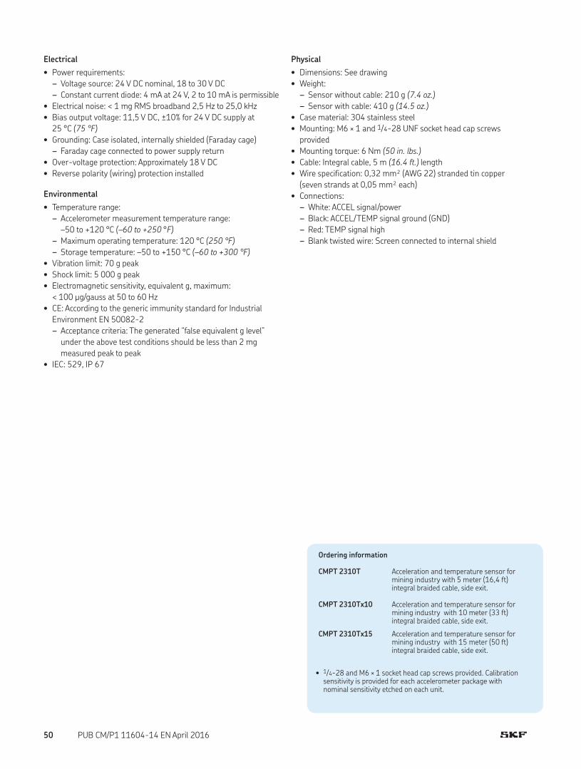
Electrical
• Power requirements:
– Voltage source: 24 V DC nominal, 18 to 30 V DC
– Constant current diode: 4 mA at 24 V, 2 to 10 mA is permissible
• Electrical noise: < 1 mg RMS broadband 2,5 Hz to 25,0 kHz
• Bias output voltage: 11,5 V DC, ±10% for 24 V DC supply at
25 °C (75 °F)
• Grounding: Case isolated, internally shielded (Faraday cage)
– Faraday cage connected to power supply return
• Over-voltage protection: Approximately 18 V DC
• Reverse polarity (wiring) protection installed
Environmental
• Temperature range:
– Accelerometer measurement temperature range:
–50 to +120 °C (–60 to +250 °F)
– Maximum operating temperature: 120 °C (250 °F)
– Storage temperature: –50 to +150 °C (–60 to +300 °F)
• Vibration limit: 70 g peak
• Shock limit: 5 000 g peak
• Electromagnetic sensitivity, equivalent g, maximum:
< 100 µg/gauss at 50 to 60 Hz
• CE: According to the generic immunity standard for Industrial
Environment EN 50082-2
– Acceptance criteria: The generated “false equivalent g level”
under the above test conditions should be less than 2 mg
measured peak to peak
• IEC: 529, IP 67
Physical
• Dimensions: See drawing
• Weight:
– Sensor without cable: 210 g (7.4 oz.)
– Sensor with cable: 410 g (14.5 oz.)
• Case material: 304 stainless steel
• Mounting: M6 × 1 and 1/4-28 UNF socket head cap screws
provided
• Mounting torque: 6 Nm (50 in. lbs.)
• Cable: Integral cable, 5 m (16.4 ft.) length
• Wire specification: 0,32 mm² (AWG 22) stranded tin copper
(seven strands at 0,05 mm² each)
• Connections:
– White: ACCEL signal/power
– Black: ACCEL/TEMP signal ground (GND)
– Red: TEMP signal high
– Blank twisted wire: Screen connected to internal shield
Ordering information
CMPT 2310T Acceleration and temperature sensor for mining industry with 5 meter (16,4 ft) integral braided cable, side exit.
CMPT 2310Tx10 Acceleration and temperature sensor for mining industry with 10 meter (33 ft) integral braided cable, side exit.
CMPT 2310Tx15 Acceleration and temperature sensor for mining industry with 15 meter (50 ft) integral braided cable, side exit.
• 1/4-28 and M6 × 1 socket head cap screws provided. Calibration sensitivity is provided for each accelerometer package with nominal sensitivity etched on each unit.
50 PUB CM/P1 11604-14 EN April 2016

CMPT 2323TSensor for mining industry, side exit, acceleration and temperature
The CMPT 2323T is a physically rugged accelerometer optimized for
use in heavy-duty environments in the following industries:
• Mining
• Mineral Processing
• Cement
In these industries, dust, mud and flying debris are commonplace,
together with low rotational speeds. When used on shakers and
screens, the accelerometer must also withstand high levels of con-
tinuous and random vibration. The sensor uses an integral cable
with stainless over-braid for mounting where protective conduit is
not available.
A higher sensitivity is used for detection of low amplitude signals
in slow moving equipment.
Features• For use with the SKF on-line system IMx-S, IMx-M, MCT and CTU
• 230 mV/g sensitivity
• Acceleration (mV/g) and temperature (mV/°C)
• Physically rugged
• Meets CE, EMC requirements
• Low profile, side exit industrial accelerometer with M6 × 1 and 1/4-28 UNF socket head cap screws provided
• 5 m (16.4 ft.) integral cable with stainless steel over-braid
• Corrosion resistant and hermetically sealed
• The internal sensor capsule is isolated from the machine ground
• Low noise, highly shock resistant
• Overload protected electronics
Dimensions
CMPT2323TS/N 00000
21,0 mm (0.83 in.)
34,0 mm (1.34 in.)
29,0 mm (1.14 in.)
ø 4,4 mm (0.17 in.)
47,2 mm (1.86 in.)
11,0 mm (0.43 in.)
14,0 mm (0.55 in.)
ACCEL signal / supply WHITE
ACCEL/TEMP GND (common) BLACK
TEMP signal high RED (CMPT 2323T only)
GND wire
SpecificationsSpecifications conform to ISA-RP-37.2 (1-95) and are typical values
referenced at 24 °C (75 °F), 24 V DC supply, 4 mA constant current
and 80 Hz.
Dynamic
• Sensitivity: 230 mV/g
• Sensitivity precision: ±10%
• Sensitivity deviation over full temperature range: 10%, approxi-
mately –5% at –50 °C (–60 °F) and +5% at +120 °C (+250 °F)
• Acceleration range: 70 g
• Amplitude linearity: < 1%, up to full scale
• Frequency range: 0,2 Hz to 10 kHz
• Transverse sensitivity: ≤ 5% of axial
• Temperature sensitivity: 10 mV/°C
• Temperature sensor measurement range: 0 to 120 °C
(30 to 250 °F)
• Temperature precision: ±1,5 °C (±2.7 °F)
51PUB CM/P1 11604-14 EN April 2016

Electrical
• Power requirements:
– Voltage source: 24 V DC nominal, 18 to 30 V DC
– Constant current diode: 4 mA at 24 V, 2 to 10 mA is
permissible.
• Electrical noise: < 1 mg RMS broadband 2,5 Hz to 25,0 kHz
• Bias output voltage: 11,5 V DC, ±10% for 24 V DC supply at
25 °C (75 °F)
• Grounding: Case isolated, internally shielded (Faraday cage)
– Faraday cage connected to power supply return
• Over-voltage protection: Approximately 18 V DC
• Reverse polarity (wiring) protection installed
Environmental
• Temperature range:
– Accelerometer measurement temperature range:
–50 to +120 °C (–60 to +250 °F)
– Maximum operating temperature: 120 °C (250 °F)
– Storage temperature: –50 to +150 °C (–60 to +300 °F)
• Vibration limit: 70 g peak
• Shock limit: 5 000 g peak
• Electromagnetic sensitivity, equivalent g, maximum:
< 100 µg/gauss at 50 to 60 Hz
• CE: According to the generic immunity standard for Industrial
Environment EN 50082-2
– Acceptance criteria: The generated “false equivalent g level”
under the above test conditions should be less than 2 mg
measured peak to peak
• IEC: 529, IP 67
Physical
• Dimensions: See drawing
• Weight:
– Sensor without cable: 210 g (7.4 oz.)
– Sensor with cable: 410 g (14.5 oz.)
• Case material: 304 stainless steel
• Mounting: M6 × 1 and 1/4-28 UNF socket head cap screws
provided
• Mounting torque: 6 Nm (50 in. lbs.)
• Cable: Integral cable, 5 m (16.4 ft.) length
• Wire specification: 0,32 mm² (AWG 22) stranded tin copper
(seven strands at 0,05 mm² each)
• Connections:
– White: ACCEL signal/power
– Black: ACCEL/TEMP signal ground (GND)
– Red: TEMP signal high
– Blank twisted wire: Screen connected to internal shield
Ordering information
CMPT 2323T Acceleration and temperature sensor for mining industry, 230 mV/g, with 5 meter (16,4 ft) integral braided cable, side exit.
CMPT 2323Tx10 Acceleration and temperature sensor for mining industry, 230 mV/g, with 10 meter (33 ft) integral braided cable, side exit.
CMPT 2323Tx15 Acceleration and temperature sensor for mining industry, 230 mV/g, with 15 meter (50 ft) integral braided cable, side exit.
• 1/4-28 and M6 × 1 socket head cap screws provided. Calibration sensitivity is provided for each accelerometer package with nominal sensitivity etched on each unit.
52 PUB CM/P1 11604-14 EN April 2016

Hazardous area approved sensors• CMSS 786A-IS / CMSS 786A-D2 Agency approved accelerometer, straight exit
• CMSS 786F-IS / CMSS 786F-D2 Agency approved accelerometer with integral cable
• CMSS 787A-IS / CMSS 787A-M8-IS / CMSS 787A-D2 / CMSS 787A-M8-D2 Agency approved accelerometer,
side exit
• CMSS 786T-IS / CMSS 786T-D2 Agency approved sensor, acceleration and temperature, straight exit
• CMSS 793-CA / CMSS 793-EE / CMSS 793-FM Superior, agency approved accelerometer, straight exit
• CMSS 797-CA / CMSS 797-EE / CMSS 797-FM Superior, agency approved accelerometer, ring mode, side exit
• CMPT 2310A / CMPT 2310TA Mining Group 1 Intrinsically Safe accelerometer (IECEx / ATEX certified)
• CMPT 2310AC / CMPT 2310ACT Mining Group 1 Intrinsically Safe accelerometer (IECEx ITA Australia certified)
CMSS 786A-IS / CMSS 786A-D2
CMSS 786F-IS /CMSS 786F-D2
CMSS 787A-IS / CMSS 787A-M8-IS /CMSS 787A-D2 / CMSS 787A-M8-D2
CMSS 786T-IS / CMSS 786T-D2 /
CMSS 793-CA / CMSS 793-EE /CMSS 793-FM
CMSS 797-CA / CMSS 797-EE /CMSS 797-FM
CMPT 2310A /CMPT 2310TA
CMPT 2310AC /CMPT 2310ACT
53PUB CM/P1 11604-14 EN April 2016

CMSS 786A-IS / CMSS 786A-D2Agency approved accelerometer, straight exit
The CMSS 786A-IS / CMSS 786A-D2 is a cost-effective sensor for
use in hazardous areas typically found in the following industries:
• Oil and Gas
• Refining
• Petrochemicals
Common applications include general purpose machines such as
pumps, motors, fans and gearboxes. The CMSS 786A-IS is particu-
larly suitable for the SKF Multilog On-line System DMx since, in this
case, no additional barriers are required for use in hazardous areas.
Features• Optimal for use with SKF on-line system DMx, WMx and IMx-M
when used with the appropriate safety barriers, accessories and/
or methods as required by the particular hazardous area
classification
• Economical, top exit design
• Rugged, corrosion resistant and hermetically sealed
• Case isolated
• Meets stringent CE, EMC requirements
• ESD protection
• Reverse wiring protection
Recommended connector/cable assembly
• CMSS 932 series
Specifications
Dynamic
• Sensitivity: 100 mV/g
• Sensitivity precision: ±5% at 25 °C (75 °F)
• Acceleration range: 80 g peak
• Amplitude non-linearity: 1%
• Frequency range:
– ±5%: 3,0 to 5 000 Hz
– ±10%: 1,0 to 9 000 Hz
– ±3 dB: 0,5 to 14 000 Hz
• Resonance frequency, mounted, nominal: 30 kHz
• Transverse sensitivity: ≤ 5% of axial
• Temperature response: See graph
Dimensions
MODEL CMSS786A-IS
S/N S00000
A B
21,6 mm (0.85 in.)
19,0 mm (0.75 in.)
22,3 mm (0.87 in.)
52,8 mm (2.08 in.)
1/4-28 mounting hole
7/8 in. hex
Two pin connector
Electrical
• Power requirements:
– Voltage source1): 18 to 30 V DC
– Constant current diode1), 2): 2 to 10 mA
• Electrical noise:
– Broadband:
· 2,5 Hz to 25 kHz: 700 µg
– Spectral:
· 10 Hz: 10 µg/√Hz
· 100 Hz: 5 µg/√Hz
· 1 000 Hz: 5 µg/√Hz
• Output impedance: < 100 Ω
• Bias output voltage: 12 V DC
• Grounding: Case isolated (> 108 Ω at 100 V), internally shielded
Limited
Lifetime
WARRANTY
54 PUB CM/P1 11604-14 EN April 2016

Environmental
• Temperature range: –50 to +120 °C (–60 to +250 °F) operating
temperature
• Vibration limit: 500 g peak
• Shock limit: 5 000 g peak
• Electromagnetic sensitivity, equivalent g, maximum: 70 µg/gauss
• Sealing: Hermetic
• Base strain sensitivity: 0,0002 g/µstrain
• Certifications: CE, CSA and ATEX (see table)
• CE: According to the generic immunity standard for Industrial
Environment EN 50082-2
– Acceptance criteria: The generated “false equivalent g level”
under the above test conditions should be less than 2 mg
measured peak to peak
Physical
• Dimensions: See drawing
• Weight: 90 g (3.2 oz.)
• Case material: 316L stainless steel
• Mounting: 1/4-28 tapped hole
• Mounting torque: 2,9 Nm (24 in. lbs.)
• Connections:
– Shell: Ground
– Pin A: Power/Signal
– Pin B: Common
• Mating connector: CMSS 932-68LC or CMSS 932-68TL, two pin,
IP 68, locking collar or twist lock
• Recommended cable: CMSS 932-SY-XXM and
CMSS 932-DY-XXM, two conductor, twisted pair, single shielded,
yellow or blue
1) To minimize the possibility of signal distortion when driving long cables with high vibration signals, 24 to 30 V DC powering is recommended. The higher level constant current source should be used when driving long cables (please consult SKF).
2) A maximum current of 6 mA is recommended for operating temperatures in excess of 100 °C (210 °F).
Ordering information
CMSS 786A-IS Agency approved accelerometer, straight exit (intrinsically safe (IS) rated).CMSS 786A-D2 Agency approved accelerometer, straight exit (non-incendive rated).• Both models with MIL-C-5015 style two pin connector. 1/4-28 and
M8 mounting studs provided. A calibration data certificate with the actual sensitivity of the accelerometer is included in each package. The nominal sensitivity is etched on each unit.
Typical temperature response
Temperature, °C (°F)
Deviation, % sensitivity+10
+5
0
–5
–10
–50 0 +50 +100 +120
(–60) (+30) (+120) (+210) (+250)
Typical frequency response
Frequency, Hz
Deviation, dB
3
2
1
0
–1
–2
–30.5 1 10 100 1 k 10 k
Agency approvals for hazardous area
CMSS 786A-IS
CSA
Intrinsically SafeClass I, Zone 0, AEx / Ex ia IIC; T4
CSA
KEMA
Class I, Division 1, Groups A, B, C, DClass II, Division 1, Groups E, F, GClass III, Division 1
ATEX Zone 0II 1 G Ex ia IIC; T4
Must be installed per drawing 12881.
CMSS 786A-D2
CSA
KEMA
Non-incendiveClass I, Division 2, Groups A, B, C, DClass I, Zone 2, Ex nA II;T4
ATEX Zone 2II 3 G Ex nA II;T4
Must be installed per drawing 13031.
55PUB CM/P1 11604-14 EN April 2016

CMSS 786F-IS / CMSS 786F-D2Agency approved accelerometer with integral cable
The CMSS 786F-IS / CMSS 786F-D2 is a cost effective sensor for
use in hazardous areas typically found in the following industries:
• Oil and Gas
• Refining
• Petrochemicals
Common applications include general purpose machines such as
pumps, motors, fans and gearboxes. The CMSS 786F-IS is particu-
larly suitable for the SKF Multilog On-line System DMx since, in this
case, no additional barriers are required for use in hazardous areas.
Features• Optimal for use with SKF on-line system DMx, WMx, IMx-S and
IMx-M when used with the appropriate safety barriers, accesso-
ries and/or methods as required by the particular hazardous area
classification
• Economical, top exit design
• Rugged, corrosion resistant and hermetically-sealed
• Case isolation
• Meets stringent CE, EMC requirements
• ESD protection
• Reverse wiring protection
Specifications
Dynamic
• Sensitivity: 100 mV/g
• Sensitivity precision: ±5% at 25 °C (75 °F)
• Acceleration range: 80 g peak
• Amplitude non-linearity: 1%
• Frequency range:
– ±10%: 1,0 to 8 000 Hz
– ±3 dB: 0,5 to 13 000 Hz
• Resonance frequency, mounted, nominal: 30 kHz
• Transverse sensitivity: ≤ 5% of axial
• Temperature response: See graph
Electrical
• Power requirements:
– Voltage source1): 18 to 30 V DC
– Constant current diode1), 2): 2 to 10 mA
• Electrical noise:
– Broadband:
· 2,5 Hz to 25 kHz: 700 µg
– Spectral:
· 10 Hz: 10 µg/√Hz
· 100 Hz: 5 µg/√Hz
· 1 000 Hz: 5 µg/√Hz
Dimensions
MODEL CMSS786F-IS
S/N S00000
19,0 mm (0.75 in.)
45,0 mm (1.77 in.)
42,7 mm (1.68 in.)
strain relief boot
Fluorine based polymer cable
70,0 mm (2.80 in.)
37,5 mm (1.50 in.)minimum
bend diameter
Hermetically sealed feed-through assembly
7/8 in. hex
1/4-28 mounting hole
56 PUB CM/P1 11604-14 EN April 2016

Physical
• Dimensions: See drawing
• Weight:
– Sensor: 90 g (3.2 oz.)
– Sensor with 5 m (16.4 ft.) integral cable supplied: 340 g (12
oz.)
• Case material: 316L stainless steel
• Mounting: 1/4-28 tapped hole
• Mounting torque: 2,9 Nm (24 in. lbs.)
• Connections:
– Shell: Ground
– Pin A: Power/Signal
– Pin B: Common
1) To minimize the possibility of signal distortion when driving long cables with high vibration signals, 24 to 30 V DC powering is recommended. The higher level constant current source should be used when driving long cables (please consult SKF).
2) A maximum current of 6 mA is recommended for operating temperatures in excess of 100 °C (210 °F).
Ordering information
CMSS 786F-IS Agency approved accelerometer with integral cable, intrinsically safe (IS) rated.CMSS 786F-D2 Agency approved accelerometer with integral cable, non-incendive rated.• Both models with 1/4-28 and M8 mounting studs provided. A
calibration data certificate with the actual sensitivity of the accelerometer is included in each package. The nominal sensitivity is etched on each unit.
Agency approvals for hazardous area
CMSS 786F-IS
CSA
Intrinsically SafeClass I, Zone 0, AEx / Ex ia IIC; T4
CSA
KEMA
Class I, Division 1, Groups A, B, C, DClass II, Division 1, Groups E, F, GClass III, Division 1
ATEX Zone 0II 1 G Ex ia IIC; T4
Must be installed per drawing 12881.
CMSS 786F-D2
CSA
KEMA
Non-incendiveClass I, Division 2, Groups A, B, C, DClass I, Zone 2, Ex nA II;T4
ATEX Zone 2II 3 G Ex nA II;T4
Must be installed per drawing 13031.
Typical temperature response
Temperature, °C (°F)
Deviation, % sensitivity+10
+5
0
–5
–10
–50 0 +50 +100 +120
(–60) (+30) (+120) (+210) (+250)
Typical frequency response
Frequency, Hz
Deviation, dB
3
2
1
0
–1
–2
–30.5 1 10 100 1 k 10 k
• Output impedance: < 100 Ω
• Bias output voltage: 12 V DC
• Grounding: Case isolated (> 108 Ω at 100 V), internally shielded
Environmental
• Temperature range: –50 to +120 °C (–60 to +250 °F) operating
temperature
• Vibration limit: 500 g peak
• Shock limit: 5 000 g peak
• Electromagnetic sensitivity, equivalent g, maximum: 70 µg/gauss
• Sealing: Hermetic
• Base strain sensitivity: 0,0002 g/µstrain
• Certifications: CE, CSA and ATEX (see table)
• CE: According to the generic immunity standard for Industrial
Environment EN 50082-2
– Acceptance criteria: The generated “false equivalent g level”
under the above test conditions should be less than 2 mg
measured peak to peak
57PUB CM/P1 11604-14 EN April 2016

The CMSS 787A-IS / CMSS 787A-D2 is a cost-effective sensor for
use in hazardous areas typically found in the following industries:
• Oil and Gas
• Refining
• Petrochemicals
Common applications include general purpose machines such as
pumps, motors, fans and gearboxes. The CMSS 787A-IS is particu-
larly suitable for the SKF Multilog On-line System DMx since, in this
case, no additional barriers are required for use in hazardous areas.
Features• Optimal for use with SKF on-line system DMx, WMx and IMx-M
when used with the appropriate safety barriers, accessories
and/or methods as required by the particular hazardous area
classification
• Low profile, side exit design
• Rugged, corrosion resistant and hermetically sealed
• Case isolated
• Meets stringent CE, EMC requirements
• ESD protection
• Reverse wiring protection
Recommended connector/cable assembly
• CMSS 932 series
Specifications
Dynamic
• Sensitivity: 100 mV/g
• Sensitivity precision: ±5% at 25 °C (75 °F)
• Acceleration range: 80 g peak
• Amplitude non-linearity: 1%
• Frequency range:
– ±10%: 1,0 to 5 000 Hz
– ±3 dB: 0,7 to 10 000 Hz
• Resonance frequency, mounted, nominal: 22 kHz
• Transverse sensitivity: ≤ 5% of axial
• Temperature response: See graph
Electrical
• Power requirements:
– Voltage source1): 18 to 30 V DC
– Constant current diode1), 2): 2 to 10 mA
CMSS 787A-IS / CMSS 787A-M8-IS / CMSS 787A-D2 / CMSS 787A-M8-D2Agency approved accelerometer with side exit
Dimensions
MODEL CMSS787A-ISS/N S0000
A B
+ –
Two pin connector MIL-C-5015
53,0 mm (2.10 in.)
37,0 mm (1.44 in.)
25,2 mm (1.00 in.)
23,0 mm (0.92 in.)
CMSS 787A-IS: 1/4-28 mounting thread CMSS 787A-M8-IS: M8 mounting thread
6,3 mm (0.25 in.)
26,0 mm (1.04 in.)
37,6 mm (1.48 in.)
1/4 in. socket head captive screw
• Electrical noise:
– Broadband:
· 2,5 Hz to 25 kHz: 700 µg
– Spectral:
· 10 Hz: 10 µg/√Hz
· 100 Hz: 5 µg/√Hz
· 1 000 Hz: 5 µg/√Hz
• Output impedance: < 100 Ω
• Bias output voltage: 12 V DC
• Grounding: Case isolated, internally shielded
Limited
Lifetime
WARRANTY
58 PUB CM/P1 11604-14 EN April 2016

Physical
• Dimensions: See drawing
• Weight: 90 g (3.2 oz.)
• Case material: 316L stainless steel
• Mounting: With 1,5 mm (0.06 in.) diameter safety wire hole
– CMSS 787A-IS: 1/4-28 tapped hole
– CMSS 787A-M8-IS: M8 captive screw
• Mounting torque: 2,9 Nm (24 in. lbs.)
• Connections:
– Shell: Ground
– Pin A: Power/Signal
– Pin B: Common
• Mating connector: CMSS 932-68LC or CMSS 932-68TL, two pin,
IP 68, locking collar or twist lock
• Recommended cable: CMSS 932-SY-XXM and
CMSS 932-DY-XXM, two conductor, twisted pair, single shielded,
yellow or blue
1) To minimize the possibility of signal distortion when driving long cables with high vibration signals, 24 to 30 V DC powering is recommended. The higher level constant current source should be used when driving long cables (please consult SKF).
2) A maximum current of 6 mA is recommended for operating temperatures in excess of 100 °C (210 °F).
Ordering information
CMSS 787A-IS Agency approved accelerometer with side exit, intrinsically safe (IS) rated.CMSS 787A-D2 Agency approved accelerometer with side exit, non-incendive rated.• Both models with MIL-C-5015 style two pin connector. 1/4-28
captive hex head screw. Calibration sensitivity is provided for each accelerometer package with nominal sensitivity etched on each unit.
CMSS 787A-M8-IS Agency approved accelerometer with side exit, intrinsically safe (IS) rated.CMSS 787A-M8-D2 Agency approved accelerometer with side exit, non-incendive rated.• Both models with MIL-C-5015 style two pin connector. M8 captive
hex head screw. A calibration data certificate with the actual sensitivity of the accelerometer is included in each package. The nominal sensitivity is etched on each unit.
Typical frequency response
Frequency, Hz
Deviation, dB
3
2
1
0
–1
–2
–30.7 1 10 100 1 k 10 k
Agency approvals for hazardous area
CMSS 787A-IS / CMSS 787A-M8-IS
CSA
Intrinsically SafeClass I, Zone 0, AEx / Ex ia IIC; T4
CSA
KEMA
Class I, Division 1, Groups A, B, C, DClass II, Division 1, Groups E, F, GClass III, Division 1
ATEX Zone 0II 1 G Ex ia IIC; T4
Must be installed per drawing 12881.
CMSS 787A-D2 / CMSS 787A-M8-D2
CSA
KEMA
Non-incendiveClass I, Division 2, Groups A, B, C, DClass I, Zone 2, Ex nA II;T4
ATEX Zone 2II 3 G Ex nA II;T4
Must be installed per drawing 13031.
Typical temperature response
Temperature, °C (°F)
Deviation, % sensitivity+10
+5
0
–5
–10
–50 0 +50 +100 +120
(–60) (+30) (+120) (+210) (+250)
Environmental
• Temperature range: –50 to +120 °C (–60 to +250 °F) operating
temperature
• Vibration limit: 500 g peak
• Shock limit: 5 000 g peak
• Electromagnetic sensitivity, equivalent g, maximum: 70 µg/gauss
• Sealing: Hermetic
• Base strain sensitivity: 0,0002 g/µstrain
• Certifications: CE, CSA and ATEX (see table)
• CE: According to the generic immunity standard for Industrial
Environment EN 50082-2
– Acceptance criteria: The generated “false equivalent g level”
under the above test conditions should be less than 2 mg
measured peak to peak
59PUB CM/P1 11604-14 EN April 2016

CMSS 786T-IS / CMSS 786T-D2Agency approved sensor, acceleration and temperature, straight exit
The CMSS 786T-IS / CMSS 786T-D2 is a cost-effective, dual out-
put sensor ideal for applications where both vibration and surface
temperature measurements are required. The sensor is suitable for
use in hazardous areas typically found in the following industries:
• Oil and Gas
• Refining
• Petrochemicals
Common applications include general purpose machines such as
pumps, motors, fans and gearboxes. The CMSS 786T-IS is particu-
larly suitable for the SKF Multilog On-line System DMx, and the
CMSS 786T-D2 is suitable for the Machine Condition Transmitters
(MCT), as in both cases no additional barriers are required for use in
hazardous areas.
Features• Optimal for use with SKF on-line systems DMx, WMx, IMx-M and
MCT when used with the appropriate safety barriers, accessories
and/or methods as required by the particular hazardous area
classification
• Economical, top exit design
• Rugged, corrosion resistant and hermetically sealed
• Case isolated
• Meets stringent CE, EMC requirements
• ESD protection
• Reverse wiring protection
Recommended connector/cable assembly
• CMSS 933 series
Specifications
Dynamic
• Sensitivity: 100 mV/g
• Sensitivity precision: ±5% at 25 °C (75 °F)
• Acceleration range: 60 g peak
• Amplitude non-linearity: 1%
• Frequency range:
– ±5%: 3,0 to 5 000 Hz
– ±10%: 1,0 to 7 000 Hz
– ±3 dB: 0,5 to 12 000 Hz
• Resonance frequency, mounted, nominal: 30 kHz
• Transverse sensitivity: ≤ 5% of axial
• Temperature response: See graph
• Temperature output sensitivity:
– ±1,5 °C (±2.7 °F): 10 mV/°C (18 mV/°F)
• Temperature measurement range: 2 to 120 °C (36 to 250 °F)
Dimensions
MODEL CMSS786T-IS
S/N S00000
A B
C
21,6 mm (0.85 in.)
22,3 mm (0.87 in.)
19,0 mm (0.75 in.)
57,2 mm (2.25 in.)
Three pin connector MIL-C-5015
7/8 in. hex
1/4-28 mounting hole
Electrical
• Power requirements:
– Voltage source: 18 to 30 V DC
– Constant current diode: 2 to 10 mA
• Electrical noise:
– Broadband:
· 2,5 Hz to 25 kHz: 700 µg
– Spectral:
· 10 Hz: 10 µg/√Hz
· 100 Hz: 5 µg/√Hz
· 1 000 Hz: 5 µg/√Hz
• Output impedance: < 100 Ω
• Bias output voltage: 12 V DC
• Grounding: Case isolated, internally shielded
Limited
Lifetime
WARRANTY
60 PUB CM/P1 11604-14 EN April 2016

Environmental
• Temperature range: –50 to +120 °C (–60 to +250 °F) operating
temperature
• Vibration limit: 500 g peak
• Shock limit: 5 000 g peak
• Electromagnetic sensitivity, equivalent g, maximum: 70 µg/gauss
• Sealing: Hermetic
• Base strain sensitivity: 0,0002 g/µstrain
• Certifications: CE, CSA and ATEX (see table)
• CE: According to the generic immunity standard for Industrial
Environment EN 50082-2
– Acceptance criteria: The generated “false equivalent g level”
under the above test conditions should be less than 2 mg
measured peak to peak
Physical
• Dimensions: See drawing
• Weight: 90 g (3.2 oz.)
• Case material: 316L stainless steel
• Mounting:
– Internal 1/4-28 thread
– M8 × 1,25 and 1/4-28 to 1/4-28 mounting studs provided
• Mounting torque: 2,9 Nm (24 in. lbs.)
• Connections:
– Pin A: Accelerometer signal/power
– Pin B: Accelerometer and temperature signal common
– Pin C: Temperature sensor signal
• Mating connector: CMSS 933-68LC or CMSS 933-68TL, three
pin, IP 68 locking collar or twist lock or three pin MIL-C-5015
style
• Recommended cable: CMSS 933-SY-XXM, three conductor, triad
cable, single shielded, yellow
Ordering information
CMSS 786T-IS Agency approved sensor, acceleration and temperature, straight exit, intrinsically safe (IS) rated.CMSS 786T-D2 Agency approved sensor, acceleration and temperature, straight exit, non-incendive rated.• Both models with MIL-C-5015 style three pin connector. 1/4-28 and
M8 mounting studs provided. A calibration data certificate with the actual sensitivity of the accelerometer is included in each package. The nominal sensitivity is etched on each unit.
Typical temperature response
Temperature, °C (°F)
Deviation, % sensitivity
+10
+5
0
–5
–10
–50 0 +50 +100 +120
(–60) (+30) (+120) (+210) (+250)
Typical frequency response
Frequency, Hz
Deviation, dB
3
2
1
0
–1
–2
–30.5 1 10 100 1 k 10 k
Agency approvals for hazardous area
CMSS 786T-IS
CSA
Intrinsically SafeClass I, Zone 0, AEx / Ex ia IIC; T4
CSA
KEMA
Class I, Division 1, Groups A, B, C, DClass II, Division 1, Groups E, F, GClass III, Division 1
ATEX Zone 0II 1 G Ex ia IIC; T4
Must be installed per drawing 12882.
CMSS 786T-D2
CSA
KEMA
Non-incendiveClass I, Division 2, Groups A, B, C, DClass I, Zone 2, Ex nA II;T4
ATEX Zone 2II 3 G Ex nA II;T4
Must be installed per drawing 13032.
61PUB CM/P1 11604-14 EN April 2016

CMSS 793-CA / CMSS 793-EE / CMSS 793-FMSuperior, agency approved accelerometer, straight exit
Ordering information
CMSS 793-CA Superior, CSA approved accelerometer, straight exit.CMSS 793-EE Superior, ATEX approved accelerometer, straight exit.CMSS 793-FM Superior, FM approved accelerometer, straight exit.• 1/4–28 mounting studs are provided for all models. A calibration data
certificate with the actual sensitivity of the accelerometer is included in each package. The nominal sensitivity is etched on each unit.
Optional accessories
CMSS 908-MD Medium duty magnetic base
The CMSS 793-CA, CMSS 793-EE and CMSS 793-FM are superior
acceleration sensors with a top exit, two pin connector and agency
approvals. They are based on the CMSS 793 sensor specifications.
Features• Agency approval
– CMSS 793-CA: Canadian Standards Association (CSA)
Class I, II, III, Division 1 certification
– CMSS 793-EE: ATEX Zone 0 intrinsically safe (IS) certification
– CMSS 793-FM: Factory Mutual (FM) intrinsically safe (IS)
certification
• Ground isolated
• Rugged construction
• Corrosion resistant and hermetically sealed for installation in high
humidity areas
• ESD protection
• Reverse wiring protection
For more information about this hazardous area approved sensor,
refer to the section Industrial accelerometers for widespread applica-
tions († page 16).
Agency approvals for hazardous area
CMSS 793-CA
CSA
Class I, Division 1, Groups A, B, C, D
Must be installed per drawing 31256700.
CMSS 793-EE
SIRA
ATEX Zone 0II 1 GEx ia IIC T4 Ga (Ta = –50 to +120 °C (–60 to +250 °F))
Must be installed per drawing 11535.
CMSS 793-FM
FM
Intrinsically SafeClass I, II, III, Division 1, Groups A, B, C, D, E, F, GNIClass I, II, III, Division 2, Groups A, B, C, D, F, G
Must be installed per document drawing set 31533600.
Limited
Lifetime
WARRANTY
62 PUB CM/P1 11604-14 EN April 2016

CMSS 797-CA / CMSS 797-EE / CMSS 797-FMSuperior, agency approved accelerometer, ring mode, side exit
Ordering information
CMSS 797-CA Superior, CSA approved accelerometer, ring mode, side exit.CMSS 797-EE Superior, ATEX approved accelerometer, ring mode, side exit.CMSS 797-FM Superior, FM approved accelerometer, ring mode, side exit.• 1/4–28 captive hex head screws are provided for all models. A
calibration data certificate with the actual sensitivity of the accelerometer is included in each package. The nominal sensitivity is etched on each unit.
The CMSS 797-CA, CMSS 797-EE and CMSS 797-FM are superior
acceleration sensors with a side exit, two pin connector and agency
approvals. They are based on the CMSS 797 sensor specification.
Features• Agency approval
– CMSS 797-CA: Canadian Standards Association (CSA)
Class I, II, III, Division 1 certification
– CMSS 797-EE: ATEX Zone 0 intrinsically safe (IS) certification
– CMSS 797-FM: Factory Mutual (FM) intrinsically safe (IS)
certification
• Rugged construction
• Corrosion resistant and hermetically sealed for installation in high
humidity areas
• Case isolated
• Meets stringent CE, EMC requirements
• ESD protection
• Reverse wiring protection
For more information about this hazardous area approved sensor,
refer to the section Industrial accelerometers for widespread applica-
tions († page 16).
Agency approvals for hazardous area
CMSS 797-CA
CSA
Class I, Division 1, Groups A, B, C, D
Must be installed per drawing 31256700.
CMSS 797-EE
SIRA
ATEX Zone 0II 1 GEx ia IIC T4 Ga (Ta = –50 to +120 °C (–60 to +250 °F))
Must be installed per drawing 11537.
CMSS 797-FM
FM
Intrinsically SafeClass I, II, III, Division 1, Groups A, B, C, D, E, F, GNIClass I, II, III, Division 2, Groups A, B, C, D, F, G
Must be installed per document drawing set 31533600.
Limited
Lifetime
WARRANTY
63PUB CM/P1 11604-14 EN April 2016

The CMPT 2310A / CMPT 2310TA models
are piezoelectric accelerometer sensors
especially made for the monitoring of
machinery operating in hazardous mining
environments. They are highly reliable with
their high shock limit, excellent thermal sta-
bility and minimum mass loading effects.
The CMPT 2310TA model sensors
includes a precision integrated circuit tem-
perature sensor. The CMPT 2310TA tem-
perature output voltage is linearly propor-
tional to the temperature (°C) and does not
require external calibration or trimming to
provide high accuracy over the full 0 to +110
°C temperature range.
The CMPT 2310A / CMPT 2310TA sensors are hermetically
sealed in a stainless steel body and have an integral stainless steel
wire over-braided cable. The sensors have low profile housing and a
side exit integral cable for use in a wide range of industrial applica-
tions where harsh operating conditions and limited mounting space
prevail. The stainless steel and hermetic construction makes them
suitable in corrosive and wet environments. The sensor cable is
double insulated and highly resistant to abrasion and wear. It has
excellent signal transmission characteristics, low capacitance,
redundant shielding and high mechanical durability. The transducer
and internal cable shield/ground are isolated from the sensor hous-
ing to prevent ground loops.
The Intrinsic Safe CMPT 2310A / CMPT 2310TA sensors can be
used with any Intrinsic Safe portable vibration data collector having
the allowable terminal and isolation parameters, as defined in the
features section.
Features• ATEX certification:
I M 1 Ex ia I Ma (–50 °C ≤ Ta ≤ +110 °C)
• IECEx certification: Ex ia I Ma (–50 °C ≤ Ta ≤ +110 °C)
• IP 67
• 100 mV/g sensitivity
• CMPT 2310TA includes an integral temperature sensor
(10 mV/°C)
• Rugged design, stainless steel hermetically sealed sensor housing
CMPT 2310A / CMPT 2310TAMining Group 1 Intrinsically Safe accelerometer (IECEx / ATEX certified)
• Integral 5 meters (16.4 feet) stainless steel wire over-braided
shielded cable
• Straightforward sensor interface with color-coded cabling
• Standard mounting techniques, utilizing a low profile side exit
cable with recessed mounting screws
• The internal sensor capsule is isolated from the machine ground
• Low noise, highly shock resistant, and overload protected elec-
tronics
Certified to the following standards• IEC Standards for IECEx
– IEC 60079-0:2011
– IEC 60079-11:2011
• Essential Health and Safety Requirements for ATEX
– EN 60079-0:2012
– EN 60079-11:2012
– EN 50303:2000
ø 21,0 mm(0.83 in.)
34,0 mm (1.34 in.)
29,0 mm (1.14 in.)
ø 4,4 mm (0.17 in.)
47,2 mm(1.86 in.)
11,0 mm (0.43 in.)
14,0 mm(0.55 in.)
ACCEL signal / supply WHITE
ACCEL/TEMP GND (common) BLACK
TEMP signal high RED (CMPT 2323TA only)
GND wire
Dimensions
CMPT 2310AS/N 00000
64 PUB CM/P1 11604-14 EN April 2016

SpecificationsSpecifications conform to ISA-RP-37.2 (1-95) and are typical values
referenced at 24 °C (75 °F), 24 V DC supply, 4 mA constant current
and 80 Hz.
Sensor Accelerometer (CMPT 2310A / CMPT 2310TA)
• Mounted base resonance: 22 kHz (nominal)
• Sensitivity: 100 mV/g, ±10%, nominal 80 Hz at 22 °C (72 °F)
• Frequency response: 2 Hz to 10 kHz, ±5%, 0,8 Hz to 15 kHz
• Isolation: Base isolated
• Acceleration output range: 70 g
• Transverse sensitivity: <5% of axial
• Accelerometer measurement temperature range: –50 to +110 °C
(–58 to +230 °F)
Sensor – Temperature (CMPT 2310TA)
• Sensitivity: 10 mV/°C
• Temperature sensor measurement range: 0 to +110 °C (32 to
+230 °F)
Electrical
• Power requirements:
– Voltage source: +24 V DC nominal, +18 to +30 V DC
– Constant current diode: 4 mA DC at +24 V DC, 2 to 10 mA is
permissible
• Acceleration sensor electrical noise: <1 mg RMS broadband
2,5 Hz to 25,0 kHz
• Acceleration sensor bias output voltage: 11,5 V DC, ±10% for
+24 V DC supply at 25 °C (77 °F)
• Over-voltage protection: Approximately 18 V DC
• Reverse polarity (wiring) Protection installed
• Settling time: 2 seconds
• Output impedance: 200 Ohms maximum
• Case isolation: >108 Ohms at 500 V
Wire connections (CMPT 2310A)
• White: ACCEL signal/power (connected to constant current source)
• Black: ACCEL signal ground (GND)
• Drain wire: Screen connected to internal shield (isolated from
case)
Wire connections (CMPT 2310TA)
• White: ACCEL signal/power (connected to constant current source)
• Black: ACCEL signal ground (GND)
• Red: Temperature signal high
• Drain wire: Screen connected to internal shield (isolated from
case)
Environmental
• Storage temperature range: –50 to +110 °C (-58 to +230 °F)
• Vibration limit: 70 g peak
• Shock limit: 5 000 g
• Electromagnetic sensitivity, equivalent g, maximum:
<100 µg/gauss at 50 to 60 Hz
• Emissions: EN 61000-6-4:2001
• Immunity: EN 61000-6-2:1999
• CE: According to the generic immunity standard for Industrial
Environment EN 50082-2
– Acceptance criteria: The generated “false equivalent g level”
under the above test conditions should be less than 2 mg
measured peak to peak
• IEC: 529, IP 67
Physical
• Dimensions: See drawing
• Weight: Sensor with cable 410 g (14.5 oz.)
• Case material: 304 stainless steel
• Sensing element/construction: PZT/Compression
• Mounting: M6 ™ 1 (30 mm long) and 1/4–28 UNF (1.25 in. long)
socket head cap screws included
• Mounting torque: 6 Nm (50 in. lbs.)
• Cable: Integral cable, 5 m (16.4 ft.)
• Wire specification: 0,32 mm2 (AWG 22) stranded tin copper
(seven strands at 0,02 mm2 each)
Intrinsically Safe Requirements
• Cable: Integral cable, 5 m (16.4 ft.)
• Certificate details: Group I
– IECEx BAS 08.0087, Ex ia I Ma (–50 °C ≤ Ta ≤ +110 °C)
– Baseefa08ATEX0268, I M 1 Ex ia I Ma (–50 °C ≤ Ta ≤ +110 °C)
• Terminal parameters: Ui = 28 V, Ii = 93 mA, Pi = 0.65 W
• 500 V isolation: Units will pass a 500 V Isolation Test
• Equipment: The equipment must be returned to the manufacturer
for maintenance or replacement
– Address:
SKF Condition Monitoring Centre (Livingston) Ltd
2 Michaelson Square, Kirkton Campus,
Livingston, United Kingdom EH54 7DP
Ordering information
Standard sensor, 5 m (16.4 ft.) configuration*Sensor with 5 m (16.4 ft.) integral cable, 1/4-28 and M6 ™ 1 socket head cap screws provided.
• CMPT 2310A Sensor for mining industry, side exit and acceleration.• CMPT 2310TA Sensor for mining industry, side exit, acceleration and
temperature.
10 m (32.8 ft.) configuration*Sensor with 10 m (32.8 ft.) integral cable, 1/4-28 and M6 ™ 1 socket head cap screws provided.
• CMPT 2310A-10 Sensor for mining industry, side exit and acceleration.
• CMPT 2310TA-10 Sensor for mining industry, side exit, acceleration and temperature.
15 m (49.2 ft.) configuration*Sensor with 15 m (49.2 ft.) integral cable, 1/4-28 and M6 ™ 1 socket head cap screws provided.
• CMPT 2310A-15 Sensor for mining industry, side exit and acceleration.
• CMPT 2310TA-15 Sensor for mining industry, side exit, acceleration and temperature.
* Calibration sensitivity is provided for each accelerometer package with nominal sensitivity etched on each unit.
65PUB CM/P1 11604-14 EN April 2016

The CMPT 2310AC / CMPT 2310ACT mod-
els are piezoelectric accelerometer sensors
especially made for the monitoring of
machinery operating in hazardous mining
environments. They are highly reliable with
their high shock limit, excellent thermal sta-
bility and minimum mass loading effects.
The CMPT 2310ACT model sensors
includes a precision integrated circuit tem-
perature sensor. The CMPT 2310ACT tem-
perature output voltage is linearly propor-
tional to the temperature (°C) and does not
require external calibration or trimming to
provide high accuracy over the full 0 to
+110 °C temperature range.
The CMPT 2310AC / CMPT 2310ACT sensors are hermetically
sealed in a stainless steel body and have an integral stainless steel
wire over-braided cable. The sensors have low profile housing and a
side exit integral cable for use in a wide range of industrial applica-
tions where harsh operating conditions and limited mounting space
prevail. The stainless steel and hermetic construction makes them
suitable in corrosive and wet environments. The sensor cable is
double insulated and highly resistant to abrasion and wear. It has
excellent signal transmission characteristics, low capacitance,
redundant shielding and high mechanical durability. The transducer
and internal cable shield/ground are isolated from the sensor hous-
ing to prevent ground loops.
The Intrinsic Safe CMPT 2310AC / CMPT 2310ACT sensors can
be used with any Intrinsic Safe portable vibration data collector hav-
ing the allowable terminal and isolation parameters, as defined in
the features section.
Features• IECEx certification: Ex ia I Ma (–50 °C ≤ Ta ≤ +110 °C)
• IP 67
• 100 mV/g sensitivity
• CMPT 2310ACT includes an integral temperature sensor
(10 mV/°C)
• Rugged design, stainless steel hermetically sealed sensor housing
CMPT 2310AC / CMPT 2310ACTMining Group 1 Intrinsically Safe accelerometer (IECEx ITA Australia certified)
• Integral 5 meters (16.4 feet) stainless steel wire over-braided
shielded cable
• Straightforward sensor interface with color-coded cabling
• Standard mounting techniques, utilizing a low profile side exit
cable with recessed mounting screws
• The internal sensor capsule is isolated from the machine ground
• Low noise, highly shock resistant, and overload protected elec-
tronics
Certified to the following standards• IEC Standards for IECEx
– IEC 60079-0:2011
– IEC 60079-11:2011
ø 21,0 mm(0.83 in.)
34,0 mm (1.34 in.)
29,0 mm (1.14 in.)
ø 4,4 mm (0.17 in.)
47,2 mm(1.86 in.)
11,0 mm (0.43 in.)
14,0 mm(0.55 in.)
ACCEL signal / supply WHITE
ACCEL/TEMP GND (common) BLACK
TEMP signal high RED (CMPT 2323TA only)
GND wire
Dimensions
CMPT 2310ACS/N 00000
66 PUB CM/P1 11604-14 EN April 2016

SpecificationsSpecifications conform to ISA-RP-37.2 (1-95) and are typical values
referenced at 24 °C (75 °F), 24 V DC supply, 4 mA constant current
and 80 Hz.
Sensor Accelerometer (CMPT 2310AC / CMPT 2310ACT)
• Mounted base resonance: 22 kHz (nominal)
• Sensitivity: 100 mV/g, ±10%, nominal 80 Hz at 22 °C (72 °F)
• Frequency response: 2 Hz to 10 kHz, ±5%, 0,8 Hz to 15 kHz
• Isolation: Base isolated
• Acceleration output range: 70 g
• Transverse sensitivity: <5% of axial
• Accelerometer measurement temperature range: –50 to +110 °C
(–58 to +230 °F)
Sensor – Temperature (CMPT 2310ACT)
• Sensitivity: 10 mV/°C
• Temperature sensor measurement range: 0 to +110 °C (32 to
+230 °F)
Electrical
• Power requirements:
– Voltage source: +24 V DC nominal, +18 to +30 V DC
– Constant current diode: 4 mA DC at +24 V DC, 2 to 10 mA is
permissible
• Acceleration sensor electrical noise: <1 mg RMS broadband
2,5 Hz to 25,0 kHz
• Acceleration sensor bias output voltage: 11,5 V DC, ±10% for
+24 V DC supply at 25 °C (77 °F)
• Over-voltage protection: Approximately 18 V DC
• Reverse polarity (wiring) Protection installed
• Settling time: 2 seconds
• Output impedance: 200 Ohms maximum
• Case isolation: >108 Ohms at 500 V
Wire connections (CMPT 2310AC)
• White: ACCEL signal/power (connected to constant current source)
• Black: ACCEL signal ground (GND)
• Drain wire: Screen connected to internal shield (isolated from
case)
Wire connections (CMPT 2310ACT)
• White: ACCEL signal/power (connected to constant current source)
• Black: ACCEL signal ground (GND)
• Red: Temperature signal high
• Drain wire: Screen connected to internal shield (isolated from
case)
Environmental
• Storage temperature range: –50 to +110 °C (-58 to +230 °F)
• Vibration limit: 70 g peak
• Shock limit: 5 000 g
• Electromagnetic sensitivity, equivalent g, maximum:
<100 µg/gauss at 50 to 60 Hz
• Emissions: EN 61000-6-4:2001
• Immunity: EN 61000-6-2:1999
• CE: According to the generic immunity standard for Industrial
Environment EN 50082-2
– Acceptance criteria: The generated “false equivalent g level”
under the above test conditions should be less than 2 mg
measured peak to peak
• IEC: 529, IP 67
Physical
• Dimensions: See drawing
• Weight: Sensor with cable 410 g (14.5 oz.)
• Case material: 304 stainless steel
• Sensing element/construction: PZT/Compression
• Mounting: M6 ™ 1 (30 mm long) and 1/4–28 UNF (1.25 in. long)
socket head cap screws included
• Mounting torque: 6 Nm (50 in. lbs.)
• Cable: Integral cable, 5 m (16.4 ft.)
• Wire specification: 0,32 mm2 (AWG 22) stranded tin copper
(seven strands at 0,02 mm2 each)
Intrinsically Safe Requirements
• Cable: Integral cable, 5 m (16.4 ft.)
• Certificate details: Group I
– IECEx ITA 13.0008X, Ex ia I Ma (–50 °C to +110 °C)
• Terminal parameters: Ui = 28 V, Ii = 93 mA, Pi = 0.65 W
• 500 V isolation: Units will pass a 500 V Isolation Test
• Equipment: The equipment must be returned to the manufacturer
for maintenance or replacement
– Address:
SKF Condition Monitoring Centre (Livingston) Ltd
2 Michaelson Square, Kirkton Campus,
Livingston, United Kingdom EH54 7DP
Ordering information
Standard sensor, 5 m (16.4 ft.) configuration*Sensor with 5 m (16.4 ft.) integral cable, 1/4-28 and M6 ™ 1 socket head cap screws provided.
• CMPT 2310AC Sensor for mining industry, side exit and acceleration.• CMPT 2310ACT Sensor for mining industry, side exit, acceleration
and temperature.
10 m (32.8 ft.) configuration*Sensor with 10 m (32.8 ft.) integral cable, 1/4-28 and M6 ™ 1 socket head cap screws provided.
• CMPT 2310AC-10 Sensor for mining industry, side exit and acceleration.
• CMPT 2310ACT-10 Sensor for mining industry, side exit, acceleration and temperature.
15 m (49.2 ft.) configuration*Sensor with 15 m (49.2 ft.) integral cable, 1/4-28 and M6 ™ 1 socket head cap screws provided.
• CMPT 2310AC-15 Sensor for mining industry, side exit and acceleration.
• CMPT 2310ACT-15 Sensor for mining industry, side exit, acceleration and temperature.
* Calibration sensitivity is provided for each accelerometer package with nominal sensitivity etched on each unit.
67PUB CM/P1 11604-14 EN April 2016

Velocity sensors• CMSS 793V series; CMSS 793V-CA / CMSS 793V-EE / CMSS 793V-FM Piezoelectric industrial velocity sensor,
straight exit
• CMSS 797V Piezoelectric industrial velocity sensor, iso-ring, side exit
• CMSS 85 series High temperature velocity sensor
CMSS 793V series CMSS 797V CMSS 85 series
68 PUB CM/P1 11604-14 EN April 2016

CMSS 793V CMSS 793V-CA / CMSS 793V-EE / CMSS 793V-FMPiezoelectric industrial velocity sensor, straight exit
The CMSS 793V is a precision velocity sensor mainly for use in the
following industries:
• Oil and Gas
• Refining
• Petrochemicals
• Power Generation
Corporate standards and practices in these industries often require
the use of velocity transducers, and piezoelectric devices such as the
CMSS 793V eliminate the moving parts associated with self-gener-
ating velocity sensors (which will lead to degradation over time). The
CMSS 793V is an accelerometer with internal integration electronics
in order to provide velocity as an output.
This series of sensor is one of the most long-standing models
from SKF, with over 25 years of installed experience, together with a
long track record of proven reliability. It is recommended for use
when the vibration signal is to be used for machinery protection
applications, where a higher precision may be required.
Common applications would include API 670 standard monitoring
of pumps, fans and compressors.
Features• Optimal for use with SKF on-line system DMx, IMx-M and MCT
when used with the appropriate safety barriers, accessories and/
or methods as required by the particular hazardous area classifi-
cation
• Rugged, corrosion resistant and hermetically sealed
• Case isolated
• Meets stringent CE, EMC requirements
• ESD protection
• Reverse wiring protection
Recommended connector/cable assembly
• CMSS 932 series
Dimensions
MODEL CMSS793V
S/N 1234
25,0 mm (0.98 in.)
25,0 mm (0.98 in.)
61,0 mm (2.42 in.)
45,0 mm (1.75 in.)
Two pin connector MIL-C-5015
15/16 in. hex
1/4-28 mounting hole
Specifications
Dynamic
• Sensitivity: 100 mV/in./s
• Sensitivity precision: ±10% at 25 °C (75 °F)
• Velocity range: 50 in./s peak Amplitude non-linearity: 1%
• Frequency range:
– 10%: 3,0 to 3 500 Hz
– ±3 dB: 2,5 to 7 000 Hz
• Resonance frequency, mounted, nominal: 15 kHz
• Transverse sensitivity: ≤ 5% of axial
• Temperature response: See graph
Limited
Lifetime
WARRANTY
69PUB CM/P1 11604-14 EN April 2016

• Vibration limit: 250 g peak
• Shock limit: 2 500 g peak
• Electromagnetic sensitivity, equivalent g, maximum:
25 µin./s/gauss
• Sealing: Hermetic
• Base strain sensitivity: 0,0005 µin./s/µstrain
• CE: According to the generic immunity standard for Industrial
Environment EN 50082-2
– Acceptance criteria: The generated “false equivalent g level”
under the above test conditions should be less than 2 mg
measured peak to peak
Physical
• Dimensions: See drawing
• Weight: 145 g (5.1 oz.)
• Case material: 316L stainless steel
• Mounting: 1/4-28 tapped hole
• Mounting torque: 2,9 Nm (24 in. lbs.)
• Connections:
– Pin A: Power/Signal
– Pin B: Common
• Mating connector: CMSS 932-68LC or CMSS 932-68TL, two pin,
IP 68 locking collar or twist lock
• Recommended cable: CMSS 932-SY-XXM and
CMSS 932-SB-XXM, two conductor, twisted pair, single shielded,
yellow or blue
1) To minimize the possibility of signal distortion when driving long cables with high vibration signals, 24 to 30 V DC powering is recommended. The higher level constant current source should be used when driving long cables (please consult SKF).
2) A maximum current of 6 mA is recommended for operating temperatures in excess of 100 °C (210 °F).
Ordering information
CMSS 793V Piezoelectric industrial velocity sensor, straight exit.• CMSS 793V-CA, CMSS 793V-EE or CMSS 793V-FM agency
approved intrinsically safe (IS) version.• All models with MIL-C-5015 style two pin connector. 1/4-28
mounting studs provided. A calibration data certificate with the actual sensitivity of the accelerometer is included in each package. The nominal sensitivity is etched on each unit.
Electrical
• Power requirements:
– Voltage source1): 18 to 30 V DC
– Constant current diode1), 2): 2 to 10 mA
• Electrical noise:
– Broadband:
· 2,5 Hz to 25 kHz: 100 µin./s
– Spectral:
· 10 Hz: 10,0 µin,/s/√Hz
· 100 Hz: 1,0 µin,/s/√Hz
· 1 000 Hz: 0,2 µin,/s/√Hz
• Output impedance: < 200 Ω
• Bias output voltage: 10 V DC
• Grounding: Case isolated, internally shielded
• Absolute phase shift, nominal: > 2°
Environmental
• Temperature range: –50 to +120 °C (–60 to +250 °F) operating
temperature
Typical frequency response
Frequency, Hz
Deviation, dB
3
2
1
0
–1
–2
–32.5 10 100 1 k 7k
Typical temperature response
Temperature, °C (°F)
Deviation, % sensitivity
+10
+5
0
–5
–10
–50 0 +50 +100 +120
(–60) (+30) (+120) (+210) (+250)
Agency approvals for hazardous area
CMSS 793V-CA
CSA
Class I, Division 1, Groups A, B, C, D
Must be installed per drawing 31256700.
CMSS 793V-EE
SIRA
ATEX Zone 0II 1 GEx ia IIC T4 Ga (Ta = –50 to +120 °C (–60 to +250 °F))
Must be installed per drawing 11535.
CMSS 793V-FM
FM
Intrinsically SafeClass I, II, III, Division 1, Groups A, B, C, D, E, F, GNIClass I, II, III, Division 2, Groups A, B, C, D, F, G
Must be installed per document drawing set 31533600.
70 PUB CM/P1 11604-14 EN April 2016

CMSS 797VPiezoelectric industrial velocity sensor, iso-ring, side exit
The CMSS 797V is a precision velocity sensor mainly for use in the
following industries:
• Oil and Gas
• Refining
• Petrochemicals
• Power Generation
Corporate standards and practices in these industries often require
the use of velocity transducers. Piezoelectric devices such as the
CMSS 797V eliminate the moving parts associated with self-gener-
ating velocity sensors (which will lead to degradation over time). The
CMSS 797V is an accelerometer with internal integration electronics
in order to provide velocity as an output.
This series of sensor is one of the most long-standing models
from SKF, with over 25 years of installed experience, together with a
long track record of proven reliability. It is recommended for use
when the vibration signal is to be used for machinery protection
applications, where a higher precision may be required.
Common applications would include API 670 standard monitoring
of pumps, fans and compressors.
Features• Optimal for use with SKF on-line system DMx, IMx and MCT
when used with the appropriate safety barriers, accessories and/
or methods as required by the particular hazardous area
classification
• Rugged, corrosion resistant and hermetically sealed
• Case isolated
• Meets stringent CE, EMC requirements
• ESD protection
• Reverse wiring protection
Recommended connector/cable assembly
• CMSS 932 series
Specifications
Dynamic
• Sensitivity: 100 mV/in./s
• Sensitivity precision: ±10% at 25 °C (75 °F)
• Velocity range: 50 in./s peak
• Amplitude non-linearity: 1%
• Frequency range:
– ±10%: 2,0 to 3 500 Hz
– ±3 dB: 1,6 to 7 000 Hz
• Resonance frequency, mounted, nominal: 18 kHz
• Transverse sensitivity: ≤ 5% of axial
• Temperature response: See graph
Dimensions
MODEL CMSS797V
S/N S00000
54,0 mm (2.15 in.)
26,0 mm (1.05 in.)
1/4-28 mounting thread
6,0 mm (0.25 in.)
Two pin connector MIL-C-5015
30,0 mm (1.20 in.)
43,0 mm (1.70 in.)
Electrical
• Power requirements:
– Voltage source1): 18 to 30 V DC
– Constant current diode1), 2): 2 to 10 mA
• Electrical noise:
– Broadband:
· 2,5 Hz to 25 kHz: 100 µin./s
– Spectral:
· 10 Hz: 10 µin./s/√Hz
· 100 Hz: 0,8 µin./s/√Hz
· 1 000 Hz: 0,1 µin./s/√Hz
• Output impedance: < 200 Ω
• Bias output voltage: 10 V DC
• Grounding: Case isolated, internally shielded
Limited
Lifetime
WARRANTY
71PUB CM/P1 11604-14 EN April 2016

Physical
• Dimensions: See drawing
• Weight: 148 g (5.2 oz.)
• Case material: 316L stainless steel
• Mounting: 1/4-28 captive socket head screw
• Mounting torque: 2,9 Nm (24 in. lbs.)
• Connections:
– Shell: Ground
– Pin A: Power/Signal
– Pin B: Common
• Mating connector: CMSS 932-68LC or CMSS 932-68TL, two pin,
IP 68, locking collar or twist lock
• Recommended cable: CMSS 932-SY-XXM and
CMSS 932-SB-XXM, two conductor, twisted pair, single shielded,
yellow or blue
1) To minimize the possibility of signal distortion when driving long cables with high vibration signals, 24 to 30 V DC powering is recommended. The higher level constant current source should be used when driving long cables (please consult SKF).
2) A maximum current of 6 mA is recommended for operating temperatures in excess of 100 °C (210 °F).
Ordering information
CMSS 797V Piezoelectric industrial velocity sensor, iso-ring, side exit.• All models with MIL-C-5015 style two pin connector. 1/4-28 captive
hex head screw mounting studs provided. A calibration data certificate with the actual sensitivity of the accelerometer is included in each package. The nominal sensitivity is etched on each unit.
Environmental
• Temperature range: –50 to +120 °C (–60 to +250 °F) operating
temperature
• Vibration limit: 250 g peak
• Shock limit: 2 500 g peak
• Electromagnetic sensitivity, equivalent g, maximum:
5 µin./s/gauss
• Sealing: Hermetic
• Base strain sensitivity: 0,004 in./s/µstrain
• CE: According to the generic immunity standard for Industrial
Environment EN 50082-2
– Acceptance criteria: The generated “false equivalent g level”
under the above test conditions should be less than 2 mg
measured peak to peak
Typical frequency response
Frequency, Hz
Deviation, dB
3
2
1
0
–1
–2
–31.6 10 100 1 k 7k
Typical temperature response
Temperature, °C (°F)
Deviation, % sensitivity
+10
+5
0
–5
–10
–50 0 +50 +100 +120
(–60) (+30) (+120) (+210) (+250)
72 PUB CM/P1 11604-14 EN April 2016

CMSS 85 seriesHigh temperature velocity sensor
The CMSS 85 series is a self-generating type velocity sensor mainly
for use in the following industries:
• Oil and Gas
• Refining
• Petrochemicals
• Power Generation
Corporate standards and practices in these industries often require
the use of velocity transducers. The use of self-generating velocity
sensors are often preferred by gas turbine original equipment man-
ufacturers (OEM's). The CMSS 85 series is designed for the high
temperature environment of the gas turbine casing and uses a fric-
tion-free, directionally independent design to maximize life and
minimize error.
Features• Typical use on gas turbine engines
• Zero friction coil
• Hermetically sealed
Response limits
Frequency, Hz
Deviation, dB
15 100 1K 2K
Dimensions
28,9 mm(1.14 in.)maximum
60,2 mm(2.37 in.)maximum
31,7 mm(1.25 in.)
8,0 mm(0.315 in.)
(+) Pin forupward motion
73PUB CM/P1 11604-14 EN April 2016

Specifications• Axis orientation: Any
• Sensitivity: 145 mV/in./s
• Sensitivity precision: ±5%
• Sensitivity versus temperature: Less than 0,02%/°C (0.01%/°F)
• Cross axis sensitivity: Less than 10%
• Acceleration range: 0 to 50 g
• Frequency range: 15 to 2 000 Hz
• Temperature limits: See temperature range table
• Displacement limits: 1,8 mm pk-pk (0.07 in. pk-pk)
• Damping (electromagnetic):
– At 20 °C (70 °F): 0,80
– At 200 °C (390 °F): 0,55
– At 375 °C (710 °F): 0,40
• Case to coil isolation:
– At 20 °C (70 °F): 100,0 MΩ minimum
– At 200 °C (390 °F): 10,0 MΩ minimum
– At 375 °C (710 °F): 1,0 MΩ minimum
• Sealing: Hermetic
• Dimensions: See drawing
• Weight: 213 g (7.5 oz.)
• Case material: Stainless steel
Temperature range
Model number
Temperature range
Coil resistance
Termination
CMSS 85-9 –55 to +375 °C (–65 to +710 °F)
125 Ω Two pin hermetically sealed connector
CMSS 85-10 –55 to +375 °C (–65 to +710 °F)
125 Ω Integral cable, 4,6 m (15 ft.)
Ordering information
CMSS 85-9 High temperature velocity sensor, up to 375 °C (710 °F).CMSS 85-10 High temperature velocity sensor with integral cable, up to 375 °C (710 °F).
Cables:• CMSS 4850-015 Armored 4,6 m (15 ft.) cable that mates to the
CMSS 85-9 velocity sensor with the two pin connector.• CMSS 4850-015-593 Unarmored 4,6 m (15 ft.) cable with only
0,6 m (2 ft.) of the cable having armor at the velocity sensor end of the cable. This cable mates to the CMSS 85-9 velocity sensor with the two pin connector.
Agency approvals for hazardous area
CMSS 85-9
CSA
Class I, Division 1, Groups A, B, C, D
Must be connected to CSA Certified Zener Barrier rated 22 V maximum, 300 Ω minimum, or 14 V maximum, 50 Ω minimum.
CMSS 85-10
CSA
Class I, Division 1, Groups A, B, C, D
Must be connected to CSA Certified Zener Barrier rated 22 V maximum and 300 Ω minimum, or 14 V maximum and 50 Ω minimum.
Cable configurations
Notes: • The "015" in the model number of the cables designates the cable length. If oth-er cable lengths are desired, specify the length in feet (i.e., 020, 025, etc.). It is preferred that cable lengths be ordered in increments of five feet, i.e., 015, 020, 025, etc. • The termination of the cable end opposite the mating to the velocity transducer is trimmed wire only. • The cable mating connectors are custom designed and proprietary assembled by the vendor and consequently are not available for on-site cable fabrication.
Fixed cable configuration
3,8 mm (0.15 in.) diameter, fourholes on 35,0 mm (1.38 in.) B.C.
Connector configuration
Bottom view
Mating connector/cable assemblyStandard models:CMSS 4850-015, 4,6 m (15 ft.)CMSS 4850-050, 15,3 m (50 ft.)
Two pin hermetic connector3/8-32 thread
3,0 m (9.8 ft.)or specify
Shielded two-conductor (20 AWG) glass insulation, inside stainless steel armor
35,0 mm (1.38 in.)
74 PUB CM/P1 11604-14 EN April 2016

Portable analysis accelerometers• CMSS 2200 / CMSS 2200-M8 Industrial accelerometer, side exit
• CMSS 2111 Small footprint accelerometer with integral cable
• CMSS 2114-K High frequency accelerometer kit
• CMSS 4370-K Triax accelerometer kit
• CMSS 2222 Intrinsically safe (IS) accelerometer for the SKF Micrologs
CMSS 2200 / CMSS 2200-M8 CMSS 2111 CMSS 2114-K
CMSS 4370-K CMSS 2222
75PUB CM/P1 11604-14 EN April 2016

Data capture from a range of sourcesSKF Microlog analyzers automatically collect both dynamic (vibra-
tion) and static (process) measurements from almost any source,
including handheld and magnetically mounted accelerometers, per-
manently mounted vibration sensors or on-line monitoring systems.
Temperature measurements can be collected with a non-contact
infrared sensor or with a contact probe.
The CMSS 2200 and CMSS 2200-M8 industrial accelerometers,
with their side exit and two pin connector, offer a low profile for
machinery with limited clearance. The sensor mounts in any
orientation.
Please refer to the Industrial accelerometers for widespread appli-
cations section earlier in this catalog for more information about this
portable sensor.
CMSS 2200 / CMSS 2200-M8Industrial accelerometer, side exit
Ordering information
CMSS 2200 Industrial accelerometer with side exit MIL-C-5015 two pin connector.• 1/4-28 and M6 mounting studs provided. Calibration sensitivity and
nominal sensitivity is provided for each accelerometer package.CMSS 2200-M8 Industrial accelerometer with side exit MIL-C-5015 two pin connector.• M8 mounting stud provided. Calibration sensitivity and nominal
sensitivity is provided for each accelerometer package.
Limited
Lifetime
WARRANTY
76 PUB CM/P1 11604-14 EN April 2016
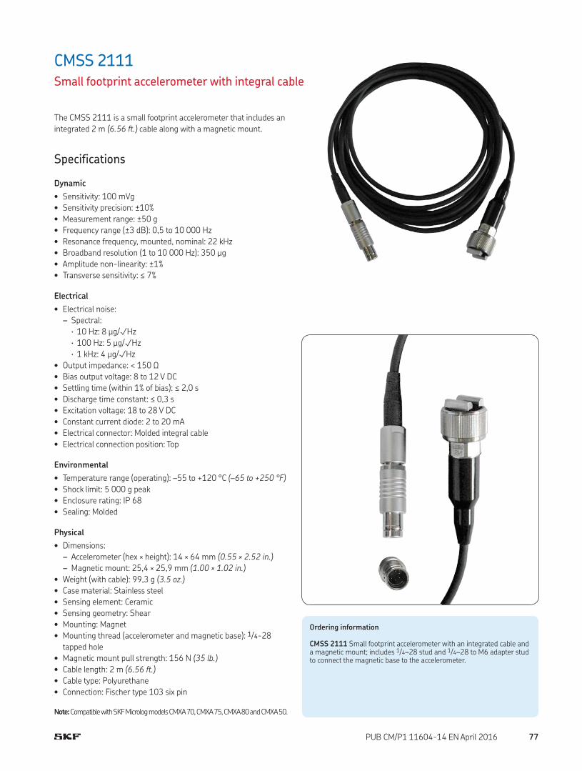
CMSS 2111Small footprint accelerometer with integral cable
The CMSS 2111 is a small footprint accelerometer that includes an
integrated 2 m (6.56 ft.) cable along with a magnetic mount.
Specifications
Dynamic
• Sensitivity: 100 mVg
• Sensitivity precision: ±10%
• Measurement range: ±50 g
• Frequency range (±3 dB): 0,5 to 10 000 Hz
• Resonance frequency, mounted, nominal: 22 kHz
• Broadband resolution (1 to 10 000 Hz): 350 µg
• Amplitude non-linearity: ±1%
• Transverse sensitivity: ≤ 7%
Electrical
• Electrical noise:
– Spectral:
· 10 Hz: 8 µg/√Hz
· 100 Hz: 5 µg/√Hz
· 1 kHz: 4 µg/√Hz
• Output impedance: < 150 Ω
• Bias output voltage: 8 to 12 V DC
• Settling time (within 1% of bias): ≤ 2,0 s
• Discharge time constant: ≤ 0,3 s
• Excitation voltage: 18 to 28 V DC
• Constant current diode: 2 to 20 mA
• Electrical connector: Molded integral cable
• Electrical connection position: Top
Environmental
• Temperature range (operating): –55 to +120 °C (–65 to +250 °F)
• Shock limit: 5 000 g peak
• Enclosure rating: IP 68
• Sealing: Molded
Physical
• Dimensions:
– Accelerometer (hex × height): 14 × 64 mm (0.55 × 2.52 in.)
– Magnetic mount: 25,4 × 25,9 mm (1.00 × 1.02 in.)
• Weight (with cable): 99,3 g (3.5 oz.)
• Case material: Stainless steel
• Sensing element: Ceramic
• Sensing geometry: Shear
• Mounting: Magnet
• Mounting thread (accelerometer and magnetic base): 1/4-28
tapped hole
• Magnetic mount pull strength: 156 N (35 lb.)
• Cable length: 2 m (6.56 ft.)
• Cable type: Polyurethane
• Connection: Fischer type 103 six pin
Note: Compatible with SKF Microlog models CMXA 70, CMXA 75, CMXA 80 and CMXA 50.
Ordering information
CMSS 2111 Small footprint accelerometer with an integrated cable and a magnetic mount; includes 1/4–28 stud and 1/4–28 to M6 adapter stud to connect the magnetic base to the accelerometer.
77PUB CM/P1 11604-14 EN April 2016

CMSS 2114-KHigh frequency accelerometer kit
The CMSS 2114-K is a high frequency accelerometer kit that
includes a high frequency cable with an adhesive mounting base.
Specifications
Dynamic
• Sensitivity: 10 mVg
• Sensitivity precision: ±15%
• Measurement range: ±500 g peak
• Amplitude non-linearity: ≤ 1%
• Frequency range (±3 dB): 5 to 60 000 Hz
• Resonance frequency, mounted, nominal: ≥ 95 kHz
• Broadband resolution (1 to 10 000 Hz): 0,002 g RMS
• Transverse sensitivity: ≤ 5%
Electrical
• Electrical noise:
– Spectral:
· 10 Hz: 160 µg/√Hz
· 100 Hz: 40 µg/√Hz
· 1 kHz: 15 µg/√Hz
· 10 kHz: 10 µg/√Hz
• Output impedance: ≤ 100 Ω
• Bias output voltage: 8 to 12 V DC
• Excitation voltage: 18 to 30 V DC
• Constant current diode: 2 to 20 mA
• Discharge time constant: 0,02 to 0,06 s
• Electrical connector: 5-44 Coaxial
• Electrical connection position: Top
Environmental
• Temperature range: –55 to +120 °C (–65 to +250 °F)
• Shock limit: 5 000 g peak
• Base strain sensitivity: ≤ 0,05 g µ
• Sealing: Welded hermetic
• CE: According to the generic immunity standard for Industrial
Environment EN 50082-2
– Acceptance criteria: The generated “false equivalent g level”
under the above test conditions should be less than 2 mg
measured peak to peak
Dimensions
352A60
10,7 mm (0.42 in.)
9,5 mm (0.38 in.)
20,6 mm (0.81 in.)
5-44 coaxial connector
2,8 mm (0.11 in.)
3,3 mm (0.13 in.)
4,6 mm (0.18 in.)
10-32 mounting hole1) 2)
1) Stud removed for sensor with adhesive mount option.
2) M6 × 0,75 thread for Metric option
Physical
• Dimensions: See drawing
• Weight: 6,0 g (0.21 oz.)
• Case material: Stainless steel
• Sensing element: Ceramic
• Sensing geometry: Shear
• Mounting thread: 10-32, male
• Mounting torque: 1,13 to 2,25 Nm (10 to 20 in. lbs.)
Note: All specifications are at room temperature unless otherwise specified. Compatible with SKF Microlog models CMXA 70, CMXA 75, CMXA 80 and CMXA 50. Loctite 454 insensitive adhesive gel is the recommended adhesive. This item is not included in the kit
78 PUB CM/P1 11604-14 EN April 2016

Adhesive mounting base
CMAC 5062 high frequency accelerometer cable
Ordering information
CMSS 2114-K High frequency accelerometer kit, including a high frequency accelerometer, cable and adhesive mounting base.
Kit contents• 352A60: High frequency constant current accelerometer
• CMAC 5062: High frequency accelerometer cable, Fischer six pin
to Microdot connector (5-44 coaxial connector)
• Adhesive mounting base
79PUB CM/P1 11604-14 EN April 2016
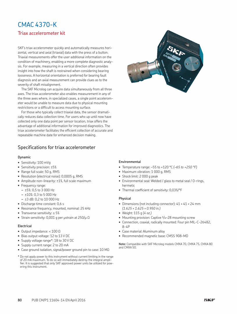
CMAC 4370-KTriax accelerometer kit
SKF’s triax accelerometer quickly and automatically measures hori-
zontal, vertical and axial (triaxial) data with the press of a button.
Triaxial measurements offer the user additional information on the
condition of machinery, enabling a more complete diagnostic analy-
sis. For example, measuring in a vertical direction often provides
insight into how the shaft is restrained when considering bearing
looseness. A horizontal orientation is preferred for bearing fault
diagnosis and an axial measurement can provide clues as to the
severity of shaft misalignment.
The SKF Microlog can acquire data simultaneously from all three
axes. The triax accelerometer also enables measurement in any of
the three axes where, in specialized cases, a single point accelerom-
eter would be unable to measure data due to physical mounting
restrictions or a difficult to access mounting surface.
For those who typically collect triaxial data, the sensor dramati-
cally reduces data collection time. For users who up until now have
collected only one data point per sensor location, triax offers the
advantage of additional information for improved diagnostics. The
triax accelerometer facilitates the efficient collection of accurate and
repeatable machine date for enhanced decision making.
Specifications for triax accelerometer
Dynamic
• Sensitivity: 100 mVg
• Sensitivity precision: ±5%
• Range full scale: 50 g, RMS
• Resolution (electrical noise): 0,0005 g, RMS
• Amplitude non-linearity: ±1%, full scale maximum
• Frequency range:
– ±5%: 0,5 to 3 000 Hz
– ±10%: 0,3 to 5 000 Hz
– ±3 dB: 0,2 to 10 000 Hz
• Discharge time constant: 0,6 s
• Resonance frequency, mounted, nominal: 25 kHz
• Transverse sensitivity: ≤ 5%
• Strain sensitivity: 0,001 g per µstrain at 250/µ Ω
Electrical
• Output impedance: < 100 Ω
• Bias output voltage: 12 to 13 V DC
• Supply voltage range*: 18 to 30 V DC
• Supply current range: 2 to 20 mA
• Case ground isolation, signal/power ground pin to case: 10 MΩ
* Do not apply power to this instrument without current limiting in the range of 20 mA maximum. To do so will immediately destroy the integral ampli-fier. It is suggested that only SKF approved power units be utilized for pow-ering this instrument.
Environmental
• Temperature range: –55 to +120 °C (–65 to +250 °F)
• Maximum vibration: 1 000 g, RMS
• Shock limit: 2 000 g peak
• Environmental seal: Welded / glass to metal seal / O-rings,
hermetic
• Thermal coefficient of sensitivity: 0,03%/°F
Physical
• Dimensions (not including connector): 41 × 41 × 24 mm
(1.625 × 1.625 × 0.950 in.)
• Weight: 115 g (4 oz.)
• Mounting provision: Captive 1/4–28 mounting screw
• Connection, coaxial, radically mounted: Four pin MIL-C-26482,
8-4P
• Case material: Aluminum alloy
• Recommended magnetic base: CMSS 908-MD
Note: Compatible with SKF Microlog models CMXA 70, CMXA 75, CMXA 80 and CMXA 50.
80 PUB CM/P1 11604-14 EN April 2016

Kit contents• Triax accelerometer
• Anti-rotation pin mounted on the bottom surface of the sensor
(the anti-rotation pin can be carefully unthreaded from the sensor
so that it can be permanently mounted)
• CMAC 5009: Triaxial accelerometer cable
• CMAC 4300: Stud adapter
• CMSS 2620-3: Studs (three)
• Calibration certificate traceable to NIST
Ordering information
CMAC 4370-K Triax accelerometer kit. Each kit includes a triax acceler-ometer, triax accelerometer cable, stud adapter and three studs. A cali-bration certificate traceable to NIST is also supplied with each instrument.
Optional Accessories
CMAC 9600-01 Toolkit for 1/4–28 studCMSS 908-MD Medium duty magnetic base
Optional accessories
CMAC 5009 triaxial accelerometer cable
CMAC 4300 stud adapter
CMSS 2620-3 stud
CMAC 9600-01 toolkit for 1/4-28 stud
Dimensions
TRIAXIAL
ACC
ELER
OMET
ER
3073M
6S/N
3
1
2
25,4 mm (1.00 in.)
Mounting surface
24,1 mm (0.95 in.)
Model 6551 fiber washerAxis #3
10-32 tapped hole for calibration, typical two places
Sig/Pwr Axis 2 Pin B
Common ground2) Pin D
Sig/Pwr Axis 3 Pin C
Sig/Pwr Axis 1 Pin A
Model 6524, 1/4-28 mounting screw. Mounting screw is detachable
Location of anti-rotation pin viewed from above1)
Axis 2
Axis 1
30,2 mm (1.19 in.)
53,8 mm (2.12 in.)
41,3 mm (1.63 in.)
10,3 mm (0.41 in.)
1) Anti-rotation pin is a 4-40 socket head cap screw, head diameter 4,65 mm (0.18 in.) maximum
2) Sig/Pwr ground return is isolated from case by > 10 MΩ
3) Torque mounting screw T-15 lb. in.4) Axis arrowheads delineate sense
and direction of positive acceleration for positive going voltage
81PUB CM/P1 11604-14 EN April 2016

Dimensions
MODEL CMSS2222
S/N S00000
A B
CMSS 2222Intrinsically safe (IS) accelerometer for the SKF Microlog series
The CMSS 2222 industrial accelerometer is intrinsically safe and is
ATEX and IECEx Group I and II approved. The CMSS 2222 acceler-
ometer is compatible with the CMXA 45/CMXA 48/CMXA 75/
CMXA 80-Z2 (ATEX Zone 2) and CMXA 51-IS (Zone 0 and Mining)
SKF Microlog series.
These approvals are most commonly needed in the following indus-
tries:
• Mining
• Petrochemicals
• Offshore
• Gas
Applications include Fans, Motors, Pumps, Compressors, Centri-
fuges, Conveyors, Air Handlers, Gearboxes, Rolls, Dyers, Presses,
Cooling, HVAC, Spindles, Machine Tooling, Process Equipment and
others.
Specifications
Dynamic
• Sensitivity: 100 mVg
• Sensitivity precision: ±10% nominal at 80 Hz
• Frequency range: 2 Hz to 10 kHz ±5% (–3 dB at 0,8 Hz)
• Mounted base resonance: 22 kHz, nominal
• Isolation: Base isolated
• Transverse sensitivity: <5%
Electrical
• Electrical noise: 0,1 mg maximum
• Bias output voltage: 10 to 12 V DC
• Current range: 0,5 to 8 mA
• Output impedance: 200 Ohms, maximum
• Case isolation: >108 Ohms at 500 Volts
Environmental
• Certified temperature range:
– Ex ia IIC T6 Ga (–55 °C ≤ Ta ≤ +60 °C) (Gas)
– Ex ia IIIC T80 °C IP65 Da (–55 °C ≤ Ta ≤ +60 °C) (Dust)*
– Ex ia I Ma (–55 °C ≤ Ta ≤ +110 °C) (Mining)
* Although the sensor is Dust certified, the SKF Micrologs are not
• Sensor Temperature Range: –55 to +140 °C (–65 to +284 °F)
• Emissions: EN61000-6-4:2007, Electromagnetic compatibility
(EMC, Generic standards – Emission standard for industrial envi-
ronments
• Immunity: EN61000-6-2:2005, Electromagnetic compatibility
(EMC), Generic standards – Immunity for industrial environments
29,0 mm(1.14 in.)
25,0 mm(0.98 in.)
25,0 mm(0.98 in.)
57,0 mm(2.24 in.)
22,0 mm(0.87 in.)
Two pin connectorMIL-C-5015
1/4-28mounting hole
7/8 in. hex
Physical
• Dimensions: See drawing
• Weight: 110 g (3.9 oz.), nominal
• Sealing: IP 67
• Mounting torque: 8 Nm (70.8 in. lbs.)
• Case material: Stainless steel
• Maximum shock: 5,000 g
• Recommended cable for CMXA 51-IS: CMAC 5115
• Recommended cable for CMXA 45/CMXA 48/CMXA 75/
CMXA 80-Z2 (ATEX Zone 2): CMAC 5209
• Recommended magnetic base: CMSS 908-MD
82 PUB CM/P1 11604-14 EN April 2016

Intrinsically Safe Requirements
• Terminal parameters (connector only):
– Ui = 28 V
– Ii = 93 mA
– Pi = 0.65 W
– Ci = 1.0 nF
– Li = negligible
• Certificate details:
– Group I
· IECEx BAS07.0037X
· Baseefa07ATEX0149X
· I M1
· Ex ia I Ma
· (–55 °C ≤ Ta ≤ +110 °C)
– Group II
· IECEx BAS07.0035X
· Baseefa07ATEX0144X
· II 1GD
· Ex ia IIC T6 Ga
· Ex ia IIIC T80 °C IP65 Da
· (–55 °C ≤ Ta ≤ +60 °C)
Ordering information
CMSS 2222 Intrinsically safe (IS) accelerometer for the SKF Microlog series
Optional accessories
CMSS 908-MD Medium duty magnetic base
Typical frequency response
Deviation, dB
50
40
30
20
10
0
–10
–20
–30
–40
–50 1 10 100 1 k 10 k 100 k
Frequency, Hz
83PUB CM/P1 11604-14 EN April 2016

Special purpose sensorsLow frequency accelerometers• CMSS 793L / CMSS 793L-FM Low frequency accelerometer, straight exit
• CMSS 797L / CMSS 797L-FM Low frequency industrial accelerometer, ring mode, side exit
• CMSS 799LF Low frequency, filtered accelerometer
High frequency accelerometer• CMSS 732A Medium-high frequency accelerometer, small diameter
Machine tool accelerometers• CMSS MT-1 Machine tool industry accelerometer, low profile
• CMSS MT-3 Machine tool industry accelerometer, low profile, adhesive mount
CMSS 732ACMSS 793L /CMSS 793L-FM
CMSS 797L /CMSS 797L-FM
CMSS 799LF
CMSS MT-1 CMSS MT-3
84 PUB CM/P1 11604-14 EN April 2016

Special purpose sensorsAcceleration and AEE sensor• CMSS 786M Industrial sensor, straight exit, acceleration and AEE
Small diameter accelerometer• CMSS 726 Small diameter, piezoelectric accelerometer
High temperature accelerometer• CMSS 376 High temperature accelerometer with charge amplifier system
CMSS 786M CMSS 726 CMSS 376
85PUB CM/P1 11604-14 EN April 2016

CMSS 793L / CMSS 793L-FMLow frequency accelerometer, straight exit
The CMSS 793L /CMSS 793L-FM is an industrial accelerometer for
higher precision measurements at rotational frequencies as low as
12 r/min. These speeds are most commonly found in the following
industries:
• Power Generation (Wind Turbines)
• Pulp and Paper
• Petrochemicals
Applications include rotors, rolls and extruders. The CMSS 793L
combines high sensitivity (to reveal low amplitude signals) with a
narrow band of frequency response. The value of the high-pass fil-
tering within the sensor makes it ideal for use in specialized, low
speed analysis tasks using portable instruments or at specific mea-
surement points on on-line systems. However, the low-pass filtering
makes the CMSS 793L unsuitable as a general purpose accelerom-
eter for rolling element bearing defect detection at more normal
rotational speeds.
Features• Optimal for use with SKF on-line system DMx, IMx-S, IMx-M and
all portable data collection instruments
• 500 mV/g high sensitivity
• Ultra low-noise electronics for clear signals at very low vibration
levels
• Low-pass filtered to attenuate high frequencies
• Hermetically sealed
• ESD protection
• Reverse wiring protection
Recommended connector/cable assembly
• CMSS 932 series
Specifications
Dynamic
• Sensitivity: 500 mV/g
• Sensitivity precision: ±5% at 25 °C (75 °F)
• Acceleration range: 10 g peak
Low frequency accelerometers
Dimensions
MODEL CMSS793L
S/N S00000
25,4 mm (1.00 in.)
25,4 mm (1.00 in.)
25,4 mm (1.00 in.)
45,0 mm (1.78 in.)
61,0 mm (2.42 in.)
15/16 in. hex
Two pin connector MIL-C-5015
1/4-28 mounting hole
• Amplitude non-linearity: 1%
• Frequency range:
– ±5%: 0,6 to 700 Hz
– ±10%: 0,4 to 1 000 Hz
– ±3 dB: 0,2 to 2 300 Hz
• Resonance frequency, mounted, nominal: 15 kHz
• Transverse sensitivity: ≤ 5% of axial
• Temperature response: See graph
Limited
Lifetime
WARRANTY
86 PUB CM/P1 11604-14 EN April 2016

Physical
• Dimensions: See drawing
• Weight: 142 g (5 oz.)
• Case material: 316L stainless steel
• Mounting: 1/4-28 tapped hole
• Mounting torque: 2,9 Nm (24 in. lbs.)
• Connections:
– Shell: Ground
– Pin A: Power/Signal
– Pin B: Common
• Mating connector: CMSS 932-68LC or CMSS 932-68TL, two pin,
IP 68, locking collar or twist lock
• Recommended cable: CMSS 932-SY-XXM and
CMSS 932-DY-XXM, two conductor, twisted pair, single or double
shielded, yellow
1) To minimize the possibility of signal distortion when driving long cables with high vibration signals, 24 to 30 V DC powering is recommended. The higher level constant current source should be used when driving long cables (please consult SKF).
2) A maximum current of 6 mA is recommended for operating temperatures in excess of 100 °C (210 °F).
Electrical
• Power requirements:
– Voltage source1): 18 to 30 V DC
– Constant current diode1), 2): 2 to 10 mA
• Electrical noise:
– Broadband:
· 2,5 Hz to 25 kHz: 8,0 µg
– Spectral:
· 2 Hz: 2,0 µg/√Hz
· 10 Hz: 0,4 µg/√Hz
· 100 Hz: 0,2 µg/√Hz
• Output impedance: < 100 Ω
• Bias output voltage: 10 V DC
• Grounding: Case isolated, internally shielded
Environmental
• Temperature range: –50 to +120 °C (–60 to +250 °F) operating
temperature
• Vibration limit: 250 g peak
• Shock limit: 5 000 g peak
• Electromagnetic sensitivity, equivalent g, maximum: 20 µg/gauss
• Sealing: Hermetic
• Base strain sensitivity: 0,0001 g/µstrain
• CE: According to the generic immunity standard for Industrial
Environment EN 50082-2
– Acceptance criteria: The generated “false equivalent g level”
under the above test conditions should be less than 2 mg
measured peak to peak
Ordering information
CMSS 793L Low frequency accelerometer, straight exit.CMSS 793L-FM FM Agency approved, intrinsically safe (IS), low frequency accelerometer, straight exit.• All models with MIL-C-5015 style two pin connector. 1/4-28 captive
hex head screw mounting studs provided. A calibration data certificate with the actual sensitivity of the accelerometer is included in each package. The nominal sensitivity is etched on each unit.
Typical frequency response
Frequency, Hz
Deviation, dB3
2
1
0
–1
–2
–30.2 1 10 100 1 k 10 k
Typical temperature response
Temperature, °C (°F)
Deviation, % sensitivity
+10
+5
0
–5
–10
–50 0 +50 +100 +150
(–60) (+30) (+120) (+210) (+300)
Agency approvals for hazardous area
CMSS 793L-FM
FM
Intrinsically SafeClass I, II, III, Division 1, Groups A, B, C, D, E, F, G
Must be installed per drawing 31413400 (in drawing set 31475400).
87PUB CM/P1 11604-14 EN April 2016

CMSS 797L / CMSS 797L-FMLow frequency industrial accelerometer, ring mode, side exit
The CMSS 797L / CMSS 797L-FM is an industrial accelerometer for
higher precision measurements at rotational frequencies as low as
12 r/min. These speeds are most commonly found in the following
industries:
• Power Generation (Wind Turbines)
• Pulp and Paper
• Petrochemicals
Applications include rotors, rolls and extruders. The CMSS 797L
combines a high sensitivity (to reveal low amplitude signals) with a
narrow band of frequency response. The value of the high-pass fil-
tering within the sensor makes it ideal for use in specialized, low
speed analysis tasks using portable instruments or at specific mea-
surement points on on-line systems. However, the low-pass filter-
ing makes the CMSS 797L unsuitable as a general purpose acceler-
ometer for rolling element bearing defect detection at more normal
rotational speeds.
Features• Optimal for use with SKF on-line system DMx, IMx-S, IMx-M and
all portable data collection instruments
• 500 mV/g high sensitivity
• Ultra low-noise electronics for clear signals at very low vibration
levels
• Low-pass filtered to attenuate high frequencies
• Hermetically sealed
• ESD protection
• Reverse wiring protection
Recommended connector/cable assembly
• CMSS 932 series
Specifications
Dynamic
• Sensitivity: 500 mV/g
• Sensitivity precision: ±5% at 25 °C (75 °F)
• Acceleration range: 10 g peak
• Amplitude non-linearity: 1%
• Frequency range:
– ±5%: 0,6 to 850 Hz
– ±10%: 0,4 to 1 500 Hz
– ±3 dB: 0,2 to 3 700 Hz
• Resonance frequency, mounted, nominal: 18 kHz
• Transverse sensitivity: ≤ 7% of axial
• Temperature response: See graph
Dimensions
MODEL CMSS797L
S/N S00000
54,0 mm (2.15 in.)
26,0 mm (1.05 in.) 1/4-28
mounting thread
6,0 mm (0.25 in.)
43,0 mm (1.70 in.)
30,0 mm (1.20 in.)
Two pin connector MIL-C-5015
Electrical
• Power requirements:
– Voltage source1): 18 to 30 V DC
– Constant current diode1), 2): 2 to 10 mA
• Electrical noise:
– Broadband:
· 2,5 Hz to 25 kHz: 12,0 µg
– Spectral:
· 2 Hz: 2,0 µg/√Hz
· 10 Hz: 0,6 µg/√Hz
· 100 Hz: 0,2 µg/√Hz
• Output impedance: < 100 Ω
• Bias output voltage: 10 V DC
• Grounding: Case isolated, internally shielded
Limited
Lifetime
WARRANTY
88 PUB CM/P1 11604-14 EN April 2016

Physical
• Dimensions: See drawing
• Weight: 148 g (5.2 oz.)
• Case material: 316L stainless steel
• Mounting: 1/4-28 captive socket head screw
• Mounting torque: 2,9 Nm (24 in. lbs.)
• Connections:
– Shell: Ground
– Pin A: Power/Signal
– Pin B: Common
• Mating connector: CMSS 932-68LC or CMSS 932-68TL, two pin,
IP 68, locking collar or twist lock
• Recommended cable: CMSS 932-SY-XXM and
CMSS 932-DY-XXM, two conductor, twisted pair, single or double
shielded, yellow
1) To minimize the possibility of signal distortion when driving long cables with high vibration signals, 24 to 30 V DC powering is recommended. The higher level constant current source should be used when driving long cables (please consult SKF).
2) A maximum current of 6 mA is recommended for operating temperatures in excess of 100 °C (210 °F).
Ordering information
CMSS 797L Low frequency, industrial accelerometer, ring mode, side exit.CMSS 797L-FM FM Agency approved, intrinsically safe (IS), low frequency industrial accelerometer, ring mode, side exit.• 1/4-28 mounting studs provided. A calibration data certificate with
the actual sensitivity of the accelerometer is included in each package. The nominal sensitivity is etched on each unit.
Environmental
• Temperature range: –50 to +120 °C (–60 to +250 °F) operating
temperature
• Vibration limit: 250 g peak
• Shock limit: 2 500 g peak
• Electromagnetic sensitivity, equivalent g, maximum: 5 µg/gauss
• Sealing: Hermetic
• Base strain sensitivity: 0,0001 g/µstrain
• CE: According to the generic immunity standard for Industrial
Environment EN 50082-2
– Acceptance criteria: The generated “false equivalent g level”
under the above test conditions should be less than 2 mg
measured peak to peak
Typical frequency response
Frequency, Hz
Deviation, dB
3
2
1
0
–1
–2
–30.2 1 10 100 1 k 3.7 k
Typical temperature response
Temperature, °C (°F)
Deviation, % sensitivity+10
+5
0
–5
–10
–50 0 +50 +100 +120
(–60) (+30) (+120) (+210) (+250)
Agency approvals for hazardous area
CMSS 797L-FM
FM
Intrinsically SafeClass I, II, III, Division 1, Groups A, B, C, D, E, F, G
Must be installed per drawing 31413400 (in drawing set 31475400).
89PUB CM/P1 11604-14 EN April 2016

CMSS 799LFLow frequency, filtered accelerometer
Low frequency measurements are critical for many industries, such
as:
• Petrochemicals
• Machine tool
• Pulp and Paper
Low frequency can be used for both condition monitoring and pro-
cess measurements. Other applications include slow speed agita-
tors, cooling towers, semi-conductor lithography and structural
testing.
Acceleration levels decrease at low frequencies. In order to have
adequate voltage signals at the acquisition equipment, this low fre-
quency sensor has an output sensitivity of 500 mV/g. Additionally,
the low-end frequency cut-off is improved down to 0,1 Hz at –3 dB
in order to read slow speed vibration signals. However, the nar-
rowed frequency response makes the CMSS 799LF unsuitable as a
general purpose accelerometer for rolling element bearing defect
detection at the usual rotational speeds.
Features• For use with the SKF on-line systems, protection systems and the
portable data collection instruments
• High sensitivity
• Ultra low-noise electronics for clear signals at very low vibration
levels
• Optimized for 15 V supply
• Filtered to eliminate high frequencies
• Hermetically sealed
• ESD protection
• Reverse wiring protection
• Fast turn-on time
• Reduced settling time
Specifications
Dynamic
• Sensitivity: 500 mV/g
• Sensitivity precision: ±5% at 25 °C (75 °F)
• Acceleration range: 10 g peak
• Amplitude non-linearity: 1%
• Frequency range:
– ±5%: 0,3 to 1 200 Hz
– ±10%: 0,2 to 1 600 Hz
– ±3 dB: 0,1 to 2 500 Hz
• Resonance frequency, mounted, nominal: 18 kHz
• Transverse sensitivity: ≤ 5% of axial
• Temperature response: See graph
Dimensions
MODEL CMSS799LF
S/N S00000
31,8 mm (1.25 in.)
66,0 mm (2.60 in.)
Two pin connector MIL-C-5015
1-1/8 in. hex
1/4-28 mounting hole
Electrical
• Power requirements:
– Voltage source1): 15 to 30 V DC
– Constant current diode1), 2): 2 to 10 mA
• Electrical noise:
– Spectral:
· 0,1 Hz: 15 µg/√Hz
· 1 Hz: 3 µg/√Hz
· 10 Hz: 1 µg/√Hz
· 100 Hz: 1 µg/√Hz
• Output impedance: < 400 Ω
• Bias output voltage: 8 V DC
• Grounding: Case isolated, internally shielded
90 PUB CM/P1 11604-14 EN April 2016

Physical
• Dimensions: See drawing
• Weight: 205 g (7.2 oz.)
• Case material: 316L stainless steel
• Mounting: 1/4-28 tapped hole
• Mounting torque: 2,9 Nm (24 in. lbs.)
• Connections:
– Shell: Ground
– Pin A: Power/Signal
– Pin B: Common
• Mating connector: CMSS 932-68LC or CMSS 932-68TL, two pin,
IP 68, locking collar or twist lock
• Recommended cable: CMSS 932-SY-XXM and
CMSS 932-DY-XXM, two conductor, twisted pair, single or double
shielded, yellow
1) To minimize the possibility of signal distortion when driving long cables with high vibration signals, 24 to 30 V DC powering is recommended. The higher level constant current source should be used when driving long cables (please consult SKF).
2) A maximum current of 6 mA is recommended for operating temperatures in excess of 100 °C (210 °F).
Ordering information
CMSS 799LF Low frequency, filtered accelerometer.• 1/4-28 mounting stud provided. A calibration data certificate with the
actual sensitivity of the accelerometer is included in each package. The nominal sensitivity is etched on each unit.
Environmental
• Temperature range: –50 to +120 °C (–60 to +250 °F) operating
temperature
• Vibration limit: 250 g peak
• Shock limit: 5 000 g peak
• Electromagnetic sensitivity, equivalent g, maximum: 150 µg/gauss
• Sealing: Hermetic
• Base strain sensitivity: 0,0005 g/µstrain
• CE: According to the generic immunity standard for Industrial
Environment EN 50082-2
– Acceptance criteria: The generated “false equivalent g level”
under the above test conditions should be less than 2 mg
measured peak to peak
Typical frequency response
Frequency, Hz
Deviation, dB
3
2
1
0
–1
–2
–30.1 1 10 100 1 k 10 k
Typical temperature response
Temperature, °C (°F)
Deviation, % sensitivity+10
+5
0
–5
–10
–50 0 +50 +100 +120
(–60) (+30) (+120) (+210) (+250)
91PUB CM/P1 11604-14 EN April 2016

CMSS 732AMedium-high frequency accelerometer, small diameter
The CMSS 732A accelerometer is a lightweight sensor that can be
used in all industries, mainly for temporary analysis purposes, or for
special on-line applications that require a high frequency measure-
ment combined with restricted space.
The small mass of the sensor makes it a good choice for use in
structural analyses such as Operating Deflection Shape (ODS).
Features• For use with all SKF on-line systems, protection systems and the
portable data collection instruments
• Wide dynamic range
• Wide frequency range
• Small size, lightweight
• Hermetically sealed
Recommended connector/cable assembly
• CMSS R1-J93-16: Coaxial, high temperature cable with 10-32
connector, 4,8 m (16 ft.)
• CMSS R1-J93-32: Coaxial, high temperature cable with 10-32
connector, 9,7 m (32 ft.)
Specifications
Dynamic
• Sensitivity: 10 mV/g
• Sensitivity precision: ±5% at 25 °C (75 °F)
• Acceleration range: 500 g peak
• Amplitude non-linearity: 1%
• Frequency range:
– ±5%: 2,0 to 15 000 Hz
– ±3 dB: 0,5 to 25,000 Hz
• Resonance frequency, mounted, nominal: 60 kHz
• Transverse sensitivity: 5% of axial
• Temperature response: See graph
Electrical
• Power requirements:
– Voltage source1): 18 to 30 V DC
– Constant current diode1), 2): 2 to 10 mA
• Electrical noise:
– Broadband:
· 2,5 Hz to 25 kHz: 200 µg
High frequency accelerometers
Dimensions
MODEL CMSS732A
S/N 00000
12,4 mm (0.49 in.)
23,6 mm (0.93 in.)
12,2 mm (0.48 in.)
10-32 mounting hole
10-32 coaxial connector
1/2 in. hex
– Spectral:
· 10 Hz: 20 µg/√Hz
· 100 Hz: 3 µg/√Hz
· 1 000 Hz: 2 µg/√Hz
· 10 000 Hz: 2 µg/√Hz
• Output impedance: < 100 Ω
• Bias output voltage: 10 V DC
• Grounding: Case isolated, internally shielded
92 PUB CM/P1 11604-14 EN April 2016

Ordering information
CMSS 732A Medium-high frequency accelerometer, small diameter.• A 10 × 32 mounting stud is provided. A calibration data certificate
with the actual sensitivity of the accelerometer is included in each package. The nominal sensitivity is etched on each unit.
Optional accessories
CMSS B13 Magnetic base mountingCMSS 30205300 Mounting stud (10 × 32 to 1/4-28) for use with the CMSS B13 magnetCMAC 5061 High frequency accelerometer cable
Optional accessories
CMSS B13 magnetic base mounting
Environmental
• Temperature range: –50 to +120 °C (–60 to +250 °F) operating
temperature
• Vibration limit: 500 g peak
• Shock limit: 5 000 g peak
• Electromagnetic sensitivity, equivalent g, maximum: 100 µg/gauss
• Sealing: Hermetic
• Base strain sensitivity: 0,005 g/µstrain
• CE: According to the generic immunity standard for Industrial
Environment EN 50082-2
– Acceptance criteria: The generated “false equivalent g level”
under the above test conditions should be less than 2 mg
measured peak to peak
Physical
• Dimensions: See drawing
• Weight: 13 g (0.46 oz.)
• Case material: 316L stainless steel
• Mounting: 10-32 tapped hole
• Mounting torque: 2,9 Nm (24 in. lbs.)
• Connections:
– Shell: Common
– Pin A: Power/Signal
• Mating connector: 10-32 coaxial connector
• Recommended cable: Coaxial, high temperature cable
1) To minimize the possibility of signal distortion when driving long cables with high vibration signals, 24 to 30 V DC powering is recommended. The higher level constant current source should be used when driving long cables (please consult SKF).
2) A maximum current of 6 mA is recommended for operating temperatures in excess of 100 °C (210 °F).
Typical frequency response
Frequency, Hz
Deviation, dB
3
2
1
0
–1
–2
–30.5 1 10 100 1 k 10 k
Typical temperature response
Temperature, °C (°F)
Deviation, % sensitivity
+10
+5
0
–5
–10
–50 0 +50 +100 +120
(–60) (+30) (+120) (+210) (+250)
CMSS B13 magnetic mounting base specifications:
• Description: Rare earth, two-pole magnet
• Pull strength: 16 kg (35 lb.)
• Outside diameter: 25 mm (1.0 in.)
• Mount: 1/4-28 tapped hole (Metric studs available)
• Knurled gripping edge
93PUB CM/P1 11604-14 EN April 2016

CMSS MT-1Machine tool industry accelerometer, low profile
The CMSS MT-1 accelerometer is optimized for use with on-line
monitoring systems in machine tool applications:
• Machine tool drives
• Machine tool gearboxes
• Machine tool carriages
The small size accelerometer is a low profile, bolt mounted sensor
used for ease of location in inaccessible and guarded locations. To
exclude noise from electrical transients, it uses a double-shielded
integral cable.
Features• For use with the SKF on-line system DMx, IMx and TMU
• Meets CE, EMC requirements
• High resistance to electrical noise
• Low profile, side exit, industrial accelerometer with captive bolt
(M8 × 1,25, 33 mm (1.3 in.) length) provided
• Compact design ideal for mounting with limited space
• Corrosion resistant and hermetically sealed
Machine tool accelerometers
Dimensions
CMSSMT1S/N 99999
12,3 mm (0.48 in.)
0,8 mm (0.03 in.)
27,0 mm (1.06 in.) 19,0 mm
(0.75 in.)
M8 × 1,25 socket cap head screw, 33 mm (1.3 in.) length
Drain (open) White (sensor – signal and power) Black (sensor – return) Screen (external shield connected to case)
8,5 mm (0.34 in.)
17,0 mm (0.67 in.)
8,5 mm (0.34 in.)
21,5 mm (0.84 in.)
36,0 mm (1.42 in.)
Outside diameter of cable, approximately 3,6 mm (0.14 in.)
Double shielded, twisted pair
Cable length, based on model number (see Ordering information)
Specifications
Dynamic
• Sensitivity: 100 mV/g
• Sensitivity precision: ±10% at 25 °C (75 °F)
• Acceleration range: 50 g peak
• Amplitude linearity: 1% of full scale
• Frequency range:
– ±3 dB: 0,32 to 10 000 Hz
• Resonance frequency, mounted, nominal: 10 kHz
• Transverse sensitivity: ≤ 5% of axial
94 PUB CM/P1 11604-14 EN April 2016

Electrical
• Power requirements:
– Voltage source: 18 to 28 V DC
– Constant current diode: 2 to 10 mA, recommended 4 mA
• Electrical noise: < 100 µV from 2,5 Hz to 25 kHz
• Output impedance: < 100 Ω
• Bias output voltage: 8 to 12 V DC
• Grounding: Case connected to outer shield, inner shield open
Environmental
• Temperature range:
– Operating: –40 to +85 °C (–40 to +185 °F)
– Storage: –55 to +120 °C (–65 to +250 °F)
• Shock limit: 7 000 g peak
• Sealing: Encapsulated
• CE: According to the generic immunity standard for Industrial
Environment EN 50082-2, Heavy Industrial
– Acceptance criteria: The generated “false equivalent g level”
under the above test conditions should be less than 2 mg
measured peak to peak
Physical
• Dimensions: See drawing
• Weight: Shipping weight, see table under "Ordering information"
• Case material: 304 stainless steel
• Mounting: M8 × 1,25 (33 mm (1.3 in.) length) captive mounting
bolt provided
• Mounting torque: 4,5 Nm (40 in. lbs.)
Cable
• Wires:
– 20 AWG Tin-plated Copper
– Stranded 19 × 0,20
– Overall diameter: 0,96 to 1,30 mm (0.04 to 0.05 in.)
• Termination:
– Signal/Power: White wire
– Common: Black wire
– Inner shield: Drain wire
– Outer shield: Braid
• Jacket:
– Fluorinated polyimide (FPI) 155
– Final diameter: 3,9 mm, ±0,20 mm (0.15 in., ±0.01 in.)
– Color: Transparent
• Rating: 600 V
• Temperature: –65 to +150 °C (–85 to +300 °F)
• Cond. resist (maximum): 32,4 Ω/km
• Insulation resist: > 1 500 MΩ × km
• Test voltage: 3 kV DC
• Weight (approximate): 30 kg/km (106 lb./mile)
• Minimum bend radius (MBR):
– Installation: 35 mm (1.38 in.)
– Dynamic use: 70 mm (2.76 in.)
Ordering information
CMSS MT-1 Machine tool industry accelerometer, low profile.
Part number Cable length Weight
CMSS MT1-16 4,88 m (16 ft.) 256 g (9 oz.)
CMSS MT1-32 9,75 m (32 ft.) 482 g (17 oz.)
CMSS MT1-64 19,51 m (64 ft.) 964 g (34 oz.)
Typical frequency response
Frequency, Hz
Deviation, dB
3
2
1
0
–1
–2
–30.3 1 10 100 1 k 10 k
95PUB CM/P1 11604-14 EN April 2016

CMSS MT-3Machine tool industry accelerometer, low profile, adhesive mount
The CMSS MT-3 is optimized for use with on-line monitoring
systems in machine tool applications:
• Machine tool spindles
The small size accelerometer is specially shaped to be adhesive
mounted in a pre-machined hole within a machine tool spindle
assembly. This ensures closest proximity to the spindle bearings,
which produce low amplitude signals easily attenuated by the
bearing housing. To exclude noise from electrical transients, it uses
a double-shielded integral cable.
Features• For use with the SKF on-line system DMx, IMx and TMU
• Machine tool spindles (adhesive mounting in pre-machined hole)
• Meets CE, EMC requirements
• High resistance to electrical noise
• Compact design ideal for mounting with limited space
• Corrosion resistant and hermetically sealed
Dimensions
CMSSMT3SQR#XXXXS/N 99999
16,0 mm (0.63 in.)
18,3 mm (0.72 in.)
18,5 mm (0.73 in.)
22,0 mm (0.87 in.)
2,5 mm (8.2 ft.) total length
Outside diameter of cable approximately 3,6 mm (0.14 in.)
Double shielded, twisted pair
Drain (open) Sensor (–) black wire Sensor (+) white wire Screen (connected to
casing)
Specifications
Dynamic
• Sensitivity: 100 mV/g
• Sensitivity precision: ±10% at 25 °C (75 °F)
• Acceleration range: 50 g peak
• Amplitude linearity: 1% of full scale
• Frequency range:
– ±3 dB: 0,32 to 10 000 Hz
• Resonance frequency, mounted, nominal: ≥ 10 kHz
• Transverse sensitivity: < 9% of axial
96 PUB CM/P1 11604-14 EN April 2016

Electrical
• Power requirements:
– Voltage source: 18 to 28 V DC
– Constant current diode: 2 to 10 mA, recommended 4 mA
• Electrical noise: < 100 µV from 2,5 Hz to 25 kHz
• Output impedance: < 100 Ω
• Bias output voltage: 8 to 12 V DC
• Grounding: Case connected to outer shield, inner shield open
Environmental
• Temperature range:
– Operating: –40 to +85 °C (–40 to +185 °F)
– Storage: –50 to +120 °C (–60 to +250 °F)
• Shock limit: 7 000 g peak
• Sealing: Encapsulated
• CE: According to the generic immunity standard for Industrial
Environment EN 50082-2, Heavy Industrial
– Acceptance criteria: The generated “false equivalent g level”
under the above test conditions should be less than 2 mg
measured peak to peak
Physical
• Dimensions: The sensor case dimensions are
18,3 × 22,0 mm (0.72 × 0.87 in.); refer to drawing for details
• Weight: 185 g (6.5 oz.)
• Case material: 316L stainless steel
• Mounting: Glued onto machine in pre-machined hole
Cable
• Wires:
– 20 AWG Tin-plated Copper
– Stranded 19 × 0,20
– Overall diameter: 0,96 to 1,30 mm (0.04 to 0.05 in.)
• Termination:
– Signal/Power: White wire
– Common: Black wire
– Inner shield: Drain wire
– Outer shield: Braid
• Jacket:
– Fluorinated polyimide (FPI) 155
– Final diameter: 3,9 mm, ±0,20 mm (0.15 in., ±0.01 in.)
– Color: Transparent
• Rating: 600 V
• Temperature: –65 to +150 °C (–85 to +300 °F)
• Cond. resist (maximum): 32,4 Ω/km
• Insulation resist: > 1 500 MΩ × km
• Test voltage: 3 kV DC
• Weight (approximate): 30 kg/km (106 lb./mile)
• Minimum bend radius (MBR):
– Installation: 35 mm (1.38 in.)
– Dynamic use: 70 mm (2.76 in.)
Ordering information
CMSS MT-3-08 Machine tool industry accelerometer, low profile, adhesive mount with 2,5 m (8 ft.) integral cable.
Typical frequency response
Frequency, Hz
Deviation, dB3
2
1
0
–1
–2
–30.3 1 10 100 1 k 10 k
97PUB CM/P1 11604-14 EN April 2016

CMSS 786MIndustrial sensor, straight exit, acceleration and AEE
AEE (SKF Acoustic Emission Enveloping) is a bearing fault detection
method developed by SKF in order to better monitor bearings. This
method of monitoring bearings breaks away from the traditional
approaches to the problem by using high frequency, acoustic emis-
sion detection in the frequency range of 250 000 to 350 000 Hz.
This technology has characteristics that set it apart from normal
vibration analysis and provides an excellent way of monitoring prob-
lems with bearings that other current technologies cannot provide.
Some of these advantages are detection of early bearing defects,
lubrication problems that stem from contamination and fretting.
The acoustic emissions transducer is sensitive to metal-to-metal
contact that occurs when bearing elements roll over a bearing race
without an intervening lubricating layer. The transducer emits a
high frequency, pulsed voltage that gives evidence of the defective
event. Thus, AEE technology, like enveloping, provides an early
warning of deteriorating mechanical condition. Combined with the
traditional information extracted from the acceleration readings, this
multi-parameter sensor delivers the basis for a broad spectrum of
data.
Features• For use with the SKF on-line systems, protection systems and the
portable data collection instruments
• Measures acceleration and AEE (SKF Acoustic Emission Envelop-
ing) units
• Meets CE requirements
• Electronic resonance damping
• Miswiring protection
• One second current settling time
• Low sensitivity to thermal gradients and base strain
Recommended connector/cable assembly
• CMSS R19-J9T2PS-XX: Shielded cable with PC06 connector
• CMSS R19SL-J9T2PS-XX: Shielded cable with splash-proof
connector
Acceleration and AEE sensors
Dimensions
MODEL CMSS786M
S/N S00000
19,0 mm (0.75 in.)
50,0 mm (2.00 in.)
Six pin connector
7/8 in. hex
1/4-28 mounting hole
Limited
Lifetime
WARRANTY
98 PUB CM/P1 11604-14 EN April 2016

Specifications
Dynamic
Accelerometer
• Sensitivity: 100 mV/g
• Sensitivity precision: ±10% at 25 °C (75 °F)
• Acceleration range: 80 g peak
• Amplitude non-linearity: 1%
• Frequency range:
– ±10%: 1,0 to 9 000 Hz
– ±20%: 0,5 to 14 000 Hz
• Resonance frequency, mounted, nominal: 22 kHz
• Transverse sensitivity: ≤ 5% of axial
• Base strain sensitivity: 0,0002 g/µstrain
• Temperature response: See graph
AEE sensor
• Sensitivity: 100 to 500 kHz
• Nominal: 10 mV/AEE ±2 dB
• Sensor capacitance, nominal: 500 pF
• Grounding: Case isolated
• Coupling capacitance to case: < 25 pF
Electrical
• Power requirements:
– Voltage source1): 18 to 30 V DC
– Constant current diode1), 2): 2 to 10 mA
• Electrical noise: 2 Hz: 20 µg/√Hz
• Output impedance: < 100 Ω
• Bias output voltage: 12 V DC
• Grounding: Case isolated, internally shielded
Environmental
• Temperature range: –50 to +120 °C (–60 to +250 °F)
• Vibration limit: 500 g peak
• Shock limit: 5 000 g peak
• Electromagnetic sensitivity, equivalent g, maximum: 70 µg/gauss
• Sealing: Hermetic
• CE: According to the generic immunity standard for Industrial
Environment EN 50082-2
– Acceptance criteria: The generated “false equivalent g level”
under the above test conditions should be less than 2 mg
measured peak to peak
Physical
• Dimensions: See drawing
• Weight: 95 g (3.4 oz.)
• Case material: 316L stainless steel
• Mounting: 1/4-28 tapped hole
• Mounting torque: 2,9 Nm (24 in. lbs.)
• Connections:
– Pin A: Case
– Pin B: AEE Sensor (–)
– Pin C: AEE Sensor (+)
– Pin D: Accelerometer, common
– Pin E: Accelerometer, power and signal
• Mating connector (six pin): CMSS R19 (meets requirements of
MIL-C-26482)
• Recommended cable: Type J9T2PS, two shielded conductor pairs,
clear fluorine based polymer jacket (100 Ω nominal)
1) To minimize the possibility of signal distortion when driving long cables with high vibration signals, 24 to 30 V DC powering is recommended. The higher level constant current source should be used when driving long cables (please consult SKF).
2) A maximum current of 6 mA is recommended for operating temperatures in excess of 100 °C (210 °F).
Ordering information
CMSS 786M Industrial sensor, straight exit, acceleration and AEE, with PC06-10-98S six pin connector.• 1/4-28 mounting studs provided. A calibration data certificate with
the actual sensitivity of the accelerometer is included in each package. The nominal sensitivity is etched on each unit.
Typical frequency response for accelerometer
Frequency, Hz
Deviation, dB
20
15
10
5
0
–5
–10
–15
–200.5 1 10 100 1 k 10 k
Typical temperature response
Temperature, °C (°F)
Deviation, % sensitivity
+10
+5
0
–5
–10
–50 0 +50 +100 +120
(–60) (+30) (+120) (+210) (+250)
99PUB CM/P1 11604-14 EN April 2016

CMSS 726Small diameter, piezoelectric accelerometer
This model is a lightweight piezoelectric accelerometer with integral
electronics, designed specifically for measuring vibration on small
structures. The unit is hermetically sealed against environmental
contamination. The CMSS 726 features a standard output sensitivity
of 100 mV/g, a high signal-to-noise ratio and a wide bandwidth.
Features• For use with the SKF on-line systems, protection systems and the
portable data collection instruments
• Meets CE requirements
• Wide frequency range
• Low noise floor
• Temperature compensated
• Wide dynamic range
• Small size, lightweight
• Hermetically sealed
Recommended connector/cable assembly
• CMSS R1-J93-16: Coaxial, high temperature cable with 10-32
connector, 4,8 m (16 ft.)
• CMSS R1-J93-32: Coaxial, high temperature cable with 10-32
connector, 9,7 m (32 ft.)
Specifications
Dynamic
• Sensitivity: 100 mV/g
• Sensitivity precision: ±5% at 25 °C (75 °F)
• Acceleration range: 80 g peak
• Amplitude non-linearity: 1%
• Frequency range:
– ±5%: 2,0 to 10 000 Hz
– ±10%: 1,0 to 12 000 Hz
– ±3 dB: 0,6 to 15 000 Hz
• Resonance frequency, mounted, nominal: 132 kHz
• Transverse sensitivity: ≤ 5% of axial
• Temperature response: See graph
Small diameter accelerometers
Dimensions
MODEL CMSS726
S/N S00000
14,0 mm (0.54 in.)
15,0 mm (0.60 in.)
25,0 mm (0.98 in.)
5/8 in. hex
10-32 coaxial connector
10-32 mounting hole
100 PUB CM/P1 11604-14 EN April 2016

Physical
• Dimensions: See drawing
• Weight: 30 g (1 oz.)
• Case material: 316L stainless steel
• Mounting: 10-32 tapped hole
• Mounting torque: 2,9 Nm (24 in. lbs.)
• Connections:
– Shell: Common
– Pin A: Power/Signal
• Mating connector: 10-32 connector
• Recommended cable: Coaxial, high temperature cable
1) To minimize the possibility of signal distortion when driving long cables with high vibration signals, 24 to 30 V DC powering is recommended. The higher level constant current source should be used when driving long cables (please consult SKF).
2) A maximum current of 6 mA is recommended for operating temperatures in excess of 100 °C (210 °F).
Ordering information
CMSS 726 Small diameter, piezoelectric accelerometer.• 10-32 mounting stud provided. A calibration data certificate with the
actual sensitivity of the accelerometer is included in each package. The nominal sensitivity is etched on each unit.
Electrical
• Power requirements:
– Voltage source1): 18 to 30 V DC
– Constant current diode1), 2): 2 to 10 mA
• Electrical noise:
– Broadband:
· 2,5 Hz to 25 kHz: 60 µg
– Spectral:
· 10 Hz: 8,0 µg/√Hz
· 100 Hz: 0,8 µg/√Hz
· 1 000 Hz: 0,3 µg/√Hz
· 10 000 Hz: 0,2 µg/√Hz
• Output impedance: < 100 Ω
• Bias output voltage: 12 V DC
• Grounding: Case isolated, internally shielded
Environmental
• Temperature range: –50 to +120 °C (–60 to +250 °F) operating
temperature
• Vibration limit: 500 g peak
• Shock limit: 5 000 g peak
• Electromagnetic sensitivity, equivalent g, maximum: 40 µg/gauss
• Sealing: Hermetic
• Base strain sensitivity: 0,002 g/µstrain
• CE: According to the generic immunity standard for Industrial
Environment EN 50082-2
– Acceptance criteria: The generated “false equivalent g level”
under the above test conditions should be less than 2 mg
measured peak to peak
Typical frequency response for accelerometer
Frequency, Hz
Deviation, dB
3
2
1
0
–1
–2
–30.6 1 10 100 1 k 10 k
Typical temperature response for accelerometer and AEE sensor
Temperature, °C (°F)
Deviation, % sensitivity
+10
+5
0
–5
–10
–50 0 +50 +100 +120
(–60) (+30) (+120) (+210) (+250)
101PUB CM/P1 11604-14 EN April 2016

The CMSS 376K high temperature acceleration system set consists
of a CMSS 376 accelerometer, CMSS 628 charge amplifier and
CMSS R1-2-J3-25 cable connector assembly.
Typically, this sensor finds its application in temperatures greater
than 150 °C (300 °F). Using this arrangement, the temperature-
sensitive converter (CMSS 628 charge amplifier) is removed from
the sensor and placed within a separate component outside the
intense heat. One end of the charge converter will be connected to
the sensor via the supplied cable and the other will be available to
connect to analysis or acquisition equipment.
Features• Operates up to 260 °C (500 °F)
• Charge output
• Hermetically sealed
• Ground isolated
• Industrial ruggedness
CMSS 376 accelerometer
Specifications
Dynamic
• Sensitivity, 25 °C (75 °F): 25 pC/g
• Amplitude non-linearity, to 250 g: 1%
• Frequency response1):
– ±5%: 3,0 to 7 000 Hz
– ±10%: 2,0 to 10 000 Hz
– ±3 dB: 1,0 to 13 000 Hz
• Resonance frequency, maximum: 32 kHz
• Transverse sensitivity, maximum: 7% of axial
• Temperature response: See graph
Electrical
• Capacitance, nominal2): 500 pF
• Resistance, minimum: 1 000 MΩ
• Grounding: Case isolated
1) As measured through a CMSS 628 charge amplifier.2) Tested at output connector.
High temperature accelerometers
CMSS 376KHigh temperature accelerometer with charge amplifier system
MODEL CMSS376
S/N 0000
CMSS 376 accelerometer dimensions
21,0 mm (0.85 in.)
44,0 mm (1.74 in.)
41,0 mm (1.62 in.)
7/8 in. hex
10-32 coaxial connector
1/4-28 mounting hole
1 mm (0.046 in.) safety wire hole
102 PUB CM/P1 11604-14 EN April 2016

Environmental
• Temperature range: –50 to +260 °C (–60 to +500 °F)
• Vibration limit: 500 g peak
• Shock limit: 5 000 g peak
• Base strain sensitivity, maximum: 0,002 g/µstrain
• Humidity limit: 100% relative
Physical
• Dimensions: See drawing
• Weight: 75 g (2.6 oz.)
• Case material: 316L stainless steel
• Mounting: 1/4-28 tapped hole for 1/4-28 stud
• Mounting torque: 2,9 Nm (24 in. lbs.)
• Output connector: 10-32 coaxial
• Cabling, mating connector: Microdot 10-32 (R1)
• Recommended cable: Low noise, fluorine based polymer jacket,
30 pF/ft; 100 pF/m (J3)
Ordering information
CMSS 376K High temperature accelerometer kit with charge amplifier. Consists of:• CMSS 376 high temperature accelerometer• CMSS 628 charge amplifier• CMSS R1-2-J3-25 cable connector assembly• 1/4-28 mounting stud• Calibration data for each set
Typical frequency response for accelerometer
Frequency, Hz
Deviation, dB
3
2
1
0
–1
–2
–31 10 100 1 k 10 k
Typical temperature response for accelerometer
Temperature, °C (°F)
Deviation, % sensitivity
+20
+10
0
–10
–20
–50 0 +50 +100 +150 +200 +260
(–60) (+30) (+120) (+210) (+300) (+390) (+500)
CMSS 628 charge amplifierThe CMSS 628 charge amplifier accepts the low level output of the
CMSS 376 high temperature accelerometer and amplifies it to
100 mV/g peak. The charge amplifier accepts constant current
power on the same line as the signal output. The interconnect cable
between the CMSS 376 and the CMSS 628 is the
CMSS R1-2-J3-25.
Specifications
Input
• Sensitivity: 25 pC/g peak nominal at 100 Hz, 25 °C (75 °F)
• Power: 2 to 10 mA constant current driven by 18 to 30 V DC
(24 V DC minimum for full output range)
Output
• CMSS 628 sensitivity: 100 mV/g peak, ±7% at 100 Hz
• CMSS 376K system sensitivity: 100 mV/g peak, ±10% at 100 Hz
and 20 °C (70 °F)
• Range: ±0,1 g to ±80 g
• Frequency: 3 Hz to 6 kHz, ±10%
• Amplitude linearity: ±1% of full scale
• Noise floor: 120 microV pk-pk
• Overload recovery time: 10 seconds for 150% overload
• Impedance: 100 Ω or less
• Bias voltage: 12 V DC, ±2 V DC
Connections
• Input: BNC (Center-HI, Shld-LO)
• Output: 5-pin terminal strip; two connections: Signal/Power (SIG),
Common (COM)
Environmental
• Operating temperature: –45 to +120 °C (–50 to +250 °F)
INPUT
NC
COM
SIG
COM
NC
76,2 mm (3.0 in.) typical
5,1 mm (0.2 in.)
63,5 mm (2.5 in.)
BNCinput
5 pins, 12,7 mm (0.5 in) diameter
5,1 mm(0.2 in.),(4 places; #10 screw clearance)
40,6 mm (1.6 in.)
25,4 mm (1.0 in.)
Maximum height with connector: 49,5 mm (1.95 in.)
CMSS 628 charge amplifier dimensions
103PUB CM/P1 11604-14 EN April 2016

Vibration sensor requirements, installation and mountingSealing requirements
The sealing specification for our sensors is defined as hermetic, if
not stated otherwise. Hermetic sealing, however, can be a vague
term. In order to quantify and compare levels of hermetic sealing,
we use a leakage scale where the leakage rate of helium is stated in
cc/second at one (1) atmosphere of pressure. SKF's industrial
sensors have the ighest hermetic seal rating in the industry. a
Helium Leak Test (HLT) is used to qualify the sealing of all sensor
designs and maintains a continuous monitoring program to ensure
the proper sealing of all hermetically-rated accelerometers.In this
context, hermetic sealing exceeds Ingress Protection ratings of IP68,
or even IP69K. The weaker link is then the cable connector assembly
with the highest Ingress Protection rating of IP68. For greater
protection against corrosion and moisture, it is recommended to fill
one-half of the connector with silicone grease. For continuous
submersion in water or other fluids, we recommend use of
accelerometer with integral cable if possible.
Cabling requirements
Cabling is one of the most important aspects of vibration sensor
installation. As with sensors and monitoring equipment, money
saved by purchasing inferior components is usually a poor invest-
ment. Time and effort to troubleshoot problems related to poor
cabling can easily cost several times the cost of the original cable.
Furthermore, measurement results can be unreliable and inaccu-
rate, thereby defeating the purpose of the condition monitoring pro-
gram in the first place. Careful attention must be given to six major
cable considerations:
• Type
• Length
• Routing
• Grounding
• Anchoring
• Environment
Each of these will be discussed on the following pages.
Cable typeVibration signals are dynamic, usually voltage-modulated and of low
amplitude (millivolts per engineering unit), thus the type of cable
used is an important factor in determining the quality of the signals
that reach the vibration monitoring device. This is true for both
handheld and permanently mounted sensors, but typically the con
sideration is more important for permanently installed sensors,
since the length of the cable is usually longer and, therefore,
exposed to more possible sources of noise. High quality cable is
recommended. In the context of vibration, “high quality” can be
defined as twisted pair, shielded cable. The sensor power and signal
are carried on individual wires and the cable’s shield(s) is grounded
at either the sensor or the vibration monitor (see the section on
Cable Grounding).
In general, coaxial cables are not recommended for use with
vibration monitors in an industrial environment. They are not
rugged enough and are susceptible to noise intrusion, since any type
of noise will be picked up on the coaxial cable’s shield and amplified
along with the signal.
Integral cables
Some vibration sensor models have a cable permanently fixed (or
“integral”) to the sensor body.
As there is no connector, this has the advantage of reducing cost
and eliminating any doubt about connectors working loose over time
and introducing noise. This feature is suited to environments where
the cable may be exposed to high ambient vibration, such as on a
vibrating screen, or the sensor is on a moving body, such as a press.
However, the integral cable brings with it significant maintenance
disadvantages. Should either the sensor or cable be damaged, the
entire sensor and cable must be replaced. In applications where the
sensor may need to be removed relatively frequently, such as with
paper machine roll changes, then an integral cable complicates the
procedure, particularly if a simple stud-mount has been used. In this
case, the cable will “coil up” and eventually break after repeated
changes (see the section on Mounting Requirements). Cable runs
greater than 5 to 10 m (16 to 33 ft.) should also be avoided – it
introduces costly installation rework in the event of a sensor change.
104 PUB CM/P1 11604-14 EN April 2016

Cable length
Length versus cable capacitance
All cables have a capacitance across their leads related to length.
Depending on the cable construction, this capacitance is generally
100 to 200 pF/m (30 to 60 pF/ft.).
After the cable length has been determined, its effect on the sen-
sor installation should first be evaluated. This is particularly impor-
tant in intrinsically safe applications, where a maximum permissible
cable capacitance is required by the certifications of the hazardous
area rated sensors and vibration monitoring device.
Length/Capacitance also has an effect on performance. Capacitive
loading attenuates the high frequency output of accelerometers. For
example, for a 160 pF/m multi-pair cable with 35 Ω/km resistance,
the effect of cable length on maximum frequency attenuation is
shown below
Connector and cable assemblies
The most common and practical approach is to use a connector and
cable assembly with a vibration sensor.
This approach has the advantage of easy and quick sensor
replacement or first installation without the need to disturb installed
field cabling. The sensor can be stud-mounted without any cable
“coil up”, and cable runs up to 20 m (65.6 ft.) remain practical. Most
SKF sensors utilize a sturdy “MIL-style” connector – when correctly
installed, these connectors do not work loose over time.
SKF offers a range of connector/cable assemblies designed to
withstand most industrial environments, from a simple fan to the
hot and wet environment of a paper machine dryer section.
Cable impedance
For monitoring vibration at higher frequencies or for applications
requiring a cable to carry a signal over a long distance with mini-
mum loss and distortion, the characteristic impedance is possibly
the most important cable parameter.
The characteristic impedance (Zo) is the combined resistive and
reactive components of the cable’s resistance to the flow of elec-
trons. Its value depends on the type of conductors, their size, spac-
ing, whether (and how tightly) they are twisted together and the type
and amount of insulating material used.
If there is a substantial mismatch between the characteristic
impedance of the transducer and the cable, or the cable and the
monitoring system, an electrical reflection will occur at the point of
the impedance mismatch. This electrical reflection will distort both
signal strength and quality. Additionally, if there is a lack of control in
the manufacture of the cable, then Zo can vary over the length of the
cable, causing electrical reflections, distortion and reduction in sig-
nal integrity within the cable itself.
For these reasons, it is important to use high quality cable that is
matched to both the transducer and the monitoring system. With
SKF sensors and monitoring equipment, best results will be
obtained with signal cable having a characteristic impedance of
120 Ω.
Cable capacitance
All cables have capacitance across their leads; therefore, the capaci-
tance load on the output of the sensor increases with cable length.
Note: Cable lengths for velocity transducers are less important since they are employed at low frequencies and contain filtering of acceleration compo-nents.
The use of high quality, twisted pair(s), shielded cable can greatly
improve the quality and reliability of vibration measurements,
together with permitting the use of longer cable runs in the installa-
tion.
Effect of cable length on maximum frequency attenuation
Distance: sensor to online device
Maximum frequency attenuation (kHz) in acceleration
100 m (330 ft.) 18,0
300 m (984 ft.) 6,0
500 m (1 640 ft.) 3,5
700 m (2 296 ft.) 2,51 000 m (3 281 ft.) 1,8
105PUB CM/P1 11604-14 EN April 2016

Cable routing
Cable routing and electromagnetic interference
Walkie-talkies, power lines or even electrical sparks may cause sig-
nal interference. The following guidelines will eliminate many mea-
surement errors due to electromagnetic interference (EMI) and elec-
trostatic discharge (ESD):
• Assure that high quality, well shielded cables are used; in such
environments, 100% shield coverage is necessary
• If cable splices are made, shielding continuity must be maintained
• Never run sensor cable alongside AC power lines
• Cables must cross AC power lines at right angles 1 m (3 ft.) away
from the power line
• Where possible, provide a separate grounded conduit to enclose
the sensor cable
• Where possible, route the cable away from radio transmission
equipment, motors/generators, transformers and other high cur-
rent charging conductors
• Finally, avoid routing the cable through areas prone to ESD,
except in applications where it is unavoidable; for example, in the
area around a paper machine, ESD cannot be escaped
Even though SKF sensors are protected against ESD failure, tempo-
rary signal distortion may appear at the monitor. Such signals usu-
ally appear as an overload or a “ski-slope” shaped FFT (Fast Fourier
Transform).
Cable routing and junction boxes
The practicalities of cabling result in the following typical arrange-
ment:
• Sensor and connector/cable assembly, typically 5 m (16.4 ft.)
length
• Junction box, mounted on or near the machine skid
• Multi-pair cabling to monitor, up to 500 m (1 640 ft.) in length,
with or without intermediate marshalling junction boxes
The short connector/cable assembly is to facilitate sensor mainte-
nance without disturbance to field cabling. When designing, attempt
to minimize the number of physical connections per “wire loop”
between sensor and monitor – it reduces the number of potential
failure points, sources of interference and is less to check when
commissioning or troubleshooting.
SKF recommendations for cables
Cable characteristic SKF recommendation
Type Twisted pair(s) or triads, shielded
Capacitance across leads < 60 pF/m (20 pF/ft.)
Impedance 120 Ω for signal cable
Size (gauge) 20 to 24 AWG (American Wire Gauge)Shield Braided or foil, single or double shield
Insulation As required by operating environment. A fluorine based polymer is standard. A fluoropolymer is recommended where fire retardation or some radiation resistance is needed.
Amplitude range versus cable capacitance
When the amplifier in the monitor drives a long cable, its perfor-
mance is limited by the current available from the Constant Current
Diode (CCD) to charge the cable capacitance at high frequencies. This
limits the amount of voltage swing from the amplifier and may
reduce the high frequency amplitude range. The reduction of the
amplitude range increases the sensor’s susceptibility to high fre-
quency amplifier overload. This will cause signal distortion and pro-
duce erroneous signals at low frequencies. Sources of high fre-
quency overload could be gear impacts or the broadband hiss of a
steam release valve. SKF sensors are protected from distortion
caused by moderate overloads.
Powering versus cable length
Proper powering will reduce signal distortion in long cable applica-
tions. It is recommended that for cable lengths over 30 m (100 ft.),
the constant current source should be 6 to 10 mA. In addition, the
voltage source should be no less than 24 V for maximum amplitude
range. Even when using very short cables, the current source should
be increased if amplifier overload signals are present or suspected.
106 PUB CM/P1 11604-14 EN April 2016

Fig. 1. Electronic circuit isolated from sensor casing.
Cable groundingThe purpose of having one or more shields around a pair of signal
lines is to reduce the coupling between the shielded signal line and
other signal lines and to reduce the intrusion of external noise.
Doing so protects the strength and fidelity of the signal of interest.
Grounding of shields, and the way in which they are grounded, has a
remarkable effect on their effectiveness. An improperly grounded
shield may actually be worse than no shield at all. In order to provide
proper shielding and prevent ground loops, cable grounding should
be carefully considered.
Ground loops
Ground loops are developed when a common line is grounded at
two points of differing electrical potential; for example, a single
shield is connected to ground on the sensor and on the instrument
side. Inadequate grounding results from not connecting the shield to
any side. As a first step to avoid ground loops, the signal, return and
internal shielding of all SKF sensors are isolated from the sensor
casing (housing).
Cable and shield
The cable shield serves to protect the signal from ESD and EMI. As a
second step to avoid ground loops, the shield should be grounded at
only one point, normally either to the instrument or to the sensor
casing. All SKF instruments are designed to accommodate ground-
ing of the sensor cable shield at the instrument († fig. 2).
Alternatively, it is possible to ground at the sensor side. Most of
SKF’s sensors are designed to allow for such a grounding scheme.
Assuming the sensor is stud-mounted to the machine and the
machine is properly grounded, the shield is thus grounded to the
machine through the sensor, and the drain wire should not be con-
nected to ground at the instrument end († fig. 3).
Non-isolated cable/connector assemblies
Within a single-shielded cable/connector assembly, “non-isolated”
means the drain wire (and hence the shield) is connected to the sen-
sor casing († fig. 3).
Within a single-shielded cable/connector assembly, “isolated”
means the drain wire (and hence the shield) are not connected to
the sensor casing, and the drain wire must be connected to ground
at the instrument end († fig. 2).
Double-shielded cable
When double-shielded cable is selected, then the outer shield is
non-isolated through the connector (to be grounded at the sensor
end only) and the inner shield is isolated (to be connected to ground
at the instrument end only) († fig. 4). Hence, double-shielded cable
cannot be selected in conjunction with isolated cable connector
assemblies.
Note: Sensors mounted in hazardous areas should be installed and ground-ed according to the installation drawings associated with their certification.
Internal shield isolated from casing
Fig. 2. Grounding at instrument side.
MODEL CMSS
S/N S12345
Ground
Instrument
Cable shield connect to instrument
Isolated cable shield
Instrument ground
– Common+ Signal
107PUB CM/P1 11604-14 EN April 2016

Fig. 4. Grounding with double-shielded cable.
MODEL CMSS
S/N S12345
Ground
Instrument
Inner shield connect to instrument
Isolated inner shield
Instrument ground
– Common+ Signal
Isolated outer shield
Sensor ground
Outer shield
connected to sensor
casing
Fig. 3. Grounding at sensor side.
MODEL CMSS
S/N S12345
Instrument
Isolated cable shield
Cable shield – connected to sensor casing
Sensor must be grounded
– Common
+ Signal
Grounding at the machine
If the machine being monitored is well grounded and the transducer
has a case terminal, the shield can be connected there. If the
machine is not well grounded, or if there is no terminal available on
the transducer, the shield should be connected to a good electrical
ground point at the machine.
However, if a junction box is used at the machine being moni-
tored, it is acceptable practice to leave the shields open at the trans-
ducers and electrically connect all of the shields together in the junc-
tion box. A ground wire should then be run from the “daisy chained”
shields to a good electrical ground at the machine being monitored.
Some cables contain more than one individually shielded signal
pair with the entire cable enclosed by an overall shield. In this case,
the recommended practice is to ground the individual shields at the
transducer and leave them open at the instrument. The overall
shield should then be grounded at the instrument and left open at
the transducers.
If a junction box is used, the overall shield must be electrically
continuous through the junction box and not connected to the other
shields.
If, when grounding at the sensor, EMI signals are found to affect
the vibration signal, a filtering capacitor (0,01 µF, 200 V low loss)
should be placed between the shield and the grounded monitor. This
capacitor prevents the passage of low frequency ground currents,
yet diverts high frequency EMI signals to ground.
Sources producing high levels of electromagnetic noise (such as
radio transmitters, static discharge and motor bush arcing) may
require a cable with dual isolated shields. In this configuration, the
outer shield is grounded to the sensor housing. The inner shield,
which is electrically isolated from the outer, is grounded to the
transmitter.
The double shielding allows electrical charges impressed on the
cable to be attenuated twice to minimize influence on the vibration
signal. Similar to the previous configuration, it is recommended that
a capacitor (0,01 µF, 200 V low loss) be placed in the terminal box
between the inner and outer shields to maximize this protection.
Note: In all cases, it is very important that the cable shield be properly grounded. Failure to do so in high EMI/ESD environments can result in damage to the sensor electronics.
108 PUB CM/P1 11604-14 EN April 2016
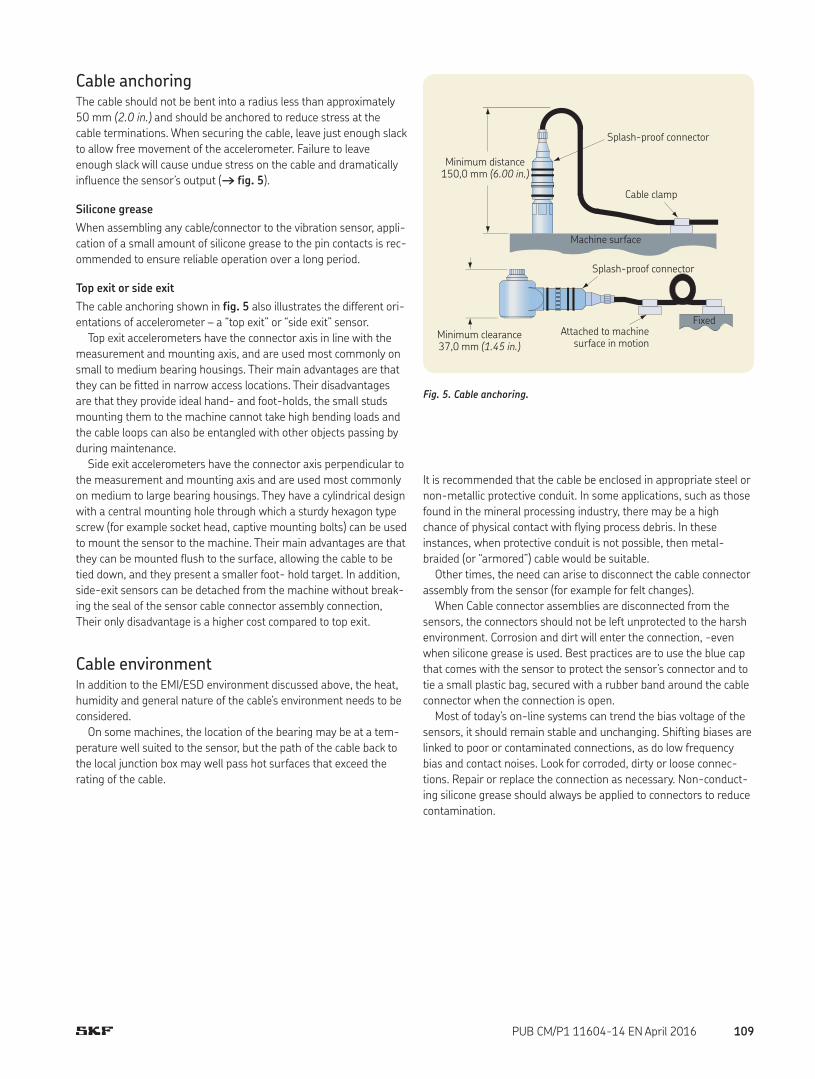
Fig. 5. Cable anchoring.
Cable anchoringThe cable should not be bent into a radius less than approximately
50 mm (2.0 in.) and should be anchored to reduce stress at the
cable terminations. When securing the cable, leave just enough slack
to allow free movement of the accelerometer. Failure to leave
enough slack will cause undue stress on the cable and dramatically
influence the sensor’s output († fig. 5).
Silicone grease
When assembling any cable/connector to the vibration sensor, appli-
cation of a small amount of silicone grease to the pin contacts is rec-
ommended to ensure reliable operation over a long period.
Top exit or side exit
The cable anchoring shown in fig. 5 also illustrates the different ori-
entations of accelerometer – a “top exit” or “side exit” sensor.
Top exit accelerometers have the connector axis in line with the
measurement and mounting axis, and are used most commonly on
small to medium bearing housings. Their main advantages are that
they can be fitted in narrow access locations. Their disadvantages
are that they provide ideal hand- and foot-holds, the small studs
mounting them to the machine cannot take high bending loads and
the cable loops can also be entangled with other objects passing by
during maintenance.
Side exit accelerometers have the connector axis perpendicular to
the measurement and mounting axis and are used most commonly
on medium to large bearing housings. They have a cylindrical design
with a central mounting hole through which a sturdy hexagon type
screw (for example socket head, captive mounting bolts) can be used
to mount the sensor to the machine. Their main advantages are that
they can be mounted flush to the surface, allowing the cable to be
tied down, and they present a smaller foot- hold target. In addition,
side-exit sensors can be detached from the machine without break-
ing the seal of the sensor cable connector assembly connection,
Their only disadvantage is a higher cost compared to top exit.
Cable environmentIn addition to the EMI/ESD environment discussed above, the heat,
humidity and general nature of the cable’s environment needs to be
considered.
On some machines, the location of the bearing may be at a tem-
perature well suited to the sensor, but the path of the cable back to
the local junction box may well pass hot surfaces that exceed the
rating of the cable.
Minimum clearance 37,0 mm (1.45 in.)
Minimum distance 150,0 mm (6.00 in.)
Splash-proof connector
Machine surface
Splash-proof connector
Attached to machine surface in motion
Fixed
Cable clamp
It is recommended that the cable be enclosed in appropriate steel or
non-metallic protective conduit. In some applications, such as those
found in the mineral processing industry, there may be a high
chance of physical contact with flying process debris. In these
instances, when protective conduit is not possible, then metal-
braided (or “armored”) cable would be suitable.
Other times, the need can arise to disconnect the cable connector
assembly from the sensor (for example for felt changes).
When Cable connector assemblies are disconnected from the
sensors, the connectors should not be left unprotected to the harsh
environment. Corrosion and dirt will enter the connection, -even
when silicone grease is used. Best practices are to use the blue cap
that comes with the sensor to protect the sensor’s connector and to
tie a small plastic bag, secured with a rubber band around the cable
connector when the connection is open.
Most of today’s on-line systems can trend the bias voltage of the
sensors, it should remain stable and unchanging. Shifting biases are
linked to poor or contaminated connections, as do low frequency
bias and contact noises. Look for corroded, dirty or loose connec-
tions. Repair or replace the connection as necessary. Non-conduct-
ing silicone grease should always be applied to connectors to reduce
contamination.
109PUB CM/P1 11604-14 EN April 2016

Handheld probe tipHandheld “stingers” are commonly used in walk-around monitoring
programs. The main task of any such program is basic screening and
seeking changes in trends, rather than absolute measurements.
Hence, the handheld method offers a fast and convenient way of
locating the sensor. The frequency attenuation experienced with the
method is still insufficient to affect the rotational vibration compo-
nents of most machines. However, good operator training and dili-
gence is required to ensure that measurements taken are reason-
ably repeatable, and consideration must be given to any higher
frequency measurements.
Because probe tips may have structural resonances in the fre-
quency range of interest, they should be made of steel and should
not exceed 150 mm (6 in.) in length.
Magnetic mountingMagnetic mounts are also popular in walk-around monitoring pro-
grams. The method removes the variations associated with hand-
held probes being applied by different users, and the frequency
response is better, although still dramatically reduced when com-
pared to stud or adhesive mounts.
Magnetic mounts are available with flat surfaces for flat locations
or two pole configurations for curved surfaces. Ensuring the magnet
is firmly attached is vital for good measurements.
Adhesive mountingIf a hole cannot be tapped properly into the machine, an adhesive
mount is recommended. The rigidity of an adhesive mount is very
dependent on the suitability of the adhesive used for the environ-
ment and whether it has been applied in accordance to the manu-
facturer’s instructions. An acrylic adhesive is the recommended
adhesive type.
Mounting pads
When using an adhesive, the
sensor may be directly attached
to the machine or onto an adhe-
sive mounting pad. The adhesive
mounting pad is flat on one side
with a threaded stud on the
other. After the pad is adhered to the machine, the sensor is torqued
onto the stud. A coupling fluid should be applied to the stud face that
mates with the sensor. Use of an adhesive mounting pad is recom-
mended if repeated removal of the sensor is required.
Note: If the circuit grounding scheme requires the sensor case to be ground-ed to the machine, then the installer must ensure that the adhesive mount-ing pad is electrically grounded to the machine. If grounding at the adhesive mounting pad is not practical, a suitable option is to place a junction box between the sensor and the monitor. The sensor shields can then be jump-ered together and a common ground established at the machine.
Mounting requirements
The mounting configuration depends upon the dynamic measure-
ment requirements, such as frequency and amplitude range. Other
factors to be considered are mounting location, prohibitions, acces-
sibility and temperature. In general, there are four mounting con-
figurations:
• Handheld probe tips
• Magnets
• Adhesives
• Threaded studs
The following table illustrates each method. A clear observation is
how the mounting method affects the frequency range that can be
measured; the less rigid the method, the lower the maximum fre-
quency.
Frequency range based on mounting techniques
Frequency, Hz
1
2
3
4 56
1 10 100 1 k 10 k 100 k
–10
0
10
20
30
–20
Relative sensitivity (dB)
65
3
2
1
4
Probe tip
Two-pole magnet
Flat magnet
Adhesive mounting
pad
Adhesive Stud
110 PUB CM/P1 11604-14 EN April 2016

Motor fin mounts
Motor fin mounts provide a mounting
location for either magnetically mounted
or permanently mounted accelerometers
on motors. They are adhesive mounted
between the cooling fins of the motor.
Threaded studsThe use of stud mounting results in the
widest frequency measurement range.
It is recommended for permanent
monitoring systems, high frequency
testing and harsh environments.
The mounting point on the structure
should be spot-faced 1,1 times greater
than the diameter of the mounting
surface of the sensor. For measure-
ments involving frequencies above 1
kHz, the surface should be flat within 25 µm (0.001 in.) and have
surface texture no greater than 0,8 µm (32 µin.). The tapped hole
must be perpendicular to the mounting surface and at least two
threads deeper than the stud. This will prevent a gap between the
sensor and the mounting surface, producing optimum frequency
response.
Proper screw torque on the mounting stud is also required.
Under-torque of the sensor reduces the stiffness of the coupling.
Over-torque can cause permanent thread damage to the sensor.
The following table shows recommended nominal mounting
torques.
Stud Stud size "A" Dimension "B" Dimension TorqueSF1 10-32 4,78 mm
(0.19 in.) 6,35 mm (0.25 in.)
20 Nm (2.3 lbf. in.)
CMAC 230 1/4-28 6,35 mm (0.25 in.)
8,90 mm (0.35 in.)
24 Nm (2.7 lbf. in.)
1/4-28 captive screw 6,35 mm (0.25 in.)
8,90 mm (0.35 in.)
30 Nm (3.4 lbf. in.)
A
> 1,1 × Sensor diameter
100 µm (0.004 in.)
– A –
25 µm (0.001 in.)
Surface finish
0,8 µm (32 µin.) RMS
"B""A"
Stud mounting surface preparation
Before stud mounting the accelerometer, silicone dielectric coupling
fluid should be applied to the mating surfaces. The coupling fluid
protects the mounting surface and optimizes the frequency
response by increasing the coupling stiffness. Suggested coupling
fluids are machine oil or vacuum grease. It is recommended that a
thread adhesive such as Loctite 222 be used.
Pipe thread adapters
Pipe thread mounting adapters pro-
vide a mounting location for either
magnetically mounted or perma-
nently mounted accelerometers, but
avoid the need to drill a hole in the
machine and spot-face. They can make use of existing plugged holes
on the machine.
Quick connects
A “quick connect” assembly allows the advantages of stud mounting
to be combined with repeated fitting and removal of the accelerom-
eter, which is most typically required in a walk-around monitoring
program.
111PUB CM/P1 11604-14 EN April 2016
Self generating velocity sensorsThese sensors wear out over time, as they contain moving parts. An
annual sensitivity check is recommended.
Summary
Vibration sensors are the initial source of machinery information
upon which productivity, product quality and personnel safety deci-
sions are based.
It is crucial that sensors be properly selected and installed to
ensure reliable signal information. Procedures should be imple-
mented to monitor the performance of all measurement channels to
further ensure the integrity of the vibration information base. Fol-
lowing this process will increase the effectiveness of your vibration
monitoring program and improve productivity of plant personnel
and equipment.
Maintenance considerations
In general, piezoelectric accelerometers are almost maintenance-
free, with only a small number of factors that need to be remem-
bered, as follows.
Sensitivity validationRegular sensitivity validation (or “calibration”) is not usually a
requirement. For example, the procedure is unnecessary in condi-
tion monitoring applications where changes in gross vibrations are
being measured and extreme accuracy is not a concern.
If high accuracy amplitude measurements are required, sensor
calibration should be verified once a year and can normally be done
on-site by a qualified technician with a vibration generator/shaker
device. A piezoelectric accelerometer cannot be adjusted, so any
variation measured must be accommodated by adjusting the sensi-
tivity used by the monitor system.
Bias output voltage monitoringA good indicator of accelerometer health can be found in its ”bias
output voltage”. The bias output voltage is the base DC voltage upon
which the AC vibration signal is carried and is typically around
12 V DC.
A regular check of the bias output voltage, or a continuous trend
in an on-line system, can reveal deterioration in the electronics
within the sensor, which may be caused by the environment (such as
temperature). It can also flag damage to cabling. Complete absence
of the bias output voltage will indicate a break in the cable or circuit.
112 PUB CM/P1 11604-14 EN April 2016

SKF’s CMSS 93X-XX cables are premium sensor cables providing
superior performance in demanding environments.
DescriptionCMSS 932 is a single or double shielded, twisted pair cable with the
conductors individually insulated with a fluorine based polymer, a
braided shield with drain wire and an outer insulated jacket also
made of a fluorine based polymer. Two insulated conductors are
cabled together with one un-insulated drain wire and two glass cord
fillers. The double shielded option adds an inner shield of aluminum
polyester foil with drain wire.
The CMSS 933 cable has the same characteristics as the
CMSS 932 cable, except it is a three-wire version for use with dual
temperature and vibration sensors. This cable does not have a
double shielded option. There are two wire colors (jacket) available:
• Yellow: For high visibility in the often dusty and debris laden
industrial environment
• Blue: For use in intrinsically safe circuits in the Oil/Gas and
Hydrocarbon Processing industries
Recommended usesThe single shield cable is recommended for use with sensors in nor-
mal industrial applications where these cable types have been his-
torically used and installed.
The double shield cable is highly recommended for use with sen-
sors in industrial installations where there is a high noise field, such
as machine tools and power generating facilities.
Vibration sensor cables and accessories
CMSS 932-SY / CMSS 932-DY / CMSS 932-SB / CMSS 933-SYBulk cable: single or double shielded, yellow or blue jacket, twisted pair or triads cables
Two-wire cable assembly
Drain wire
Jacket Shield Filler
Insulation Conductor
113PUB CM/P1 11604-14 EN April 2016

– Color code:
· Conductor: Black and white pair
· Jacket: Yellow (Y) or blue (B)
– Color code for CMSS 932:
· A = White = Acceleration signal/power
· B = Black = Common
– Color code for CMSS 933:
· A = Red = Acceleration signal/power
· B = Black = Acceleration and temperature common
· C = White = Temperature signal
– Dimensions:
· Conductor: 0,96 mm (0.038 in.) nominal
· Insulation: 1,40 mm (0.058 in.) nominal
· Drain wire: 0,61 mm (0.024 in.) nominal
· Shield: 3,50 mm (0.138 in.) nominal
· Jacket: 4,80 mm, ±0,1 mm (0.190 in., ±0.005 in.)
Ordering information
CMSS 932-SY-150M Two-conductor, twisted pair, single shield, yellow cable with continuous cable length, 150 m (500 ft.) spool.CMSS 932-SY-300M Two-conductor, twisted pair, single shield, yellow cable with continuous cable length, 300 m (1 000 ft.) spool.CMSS 932-DY-150M Two-conductor, twisted pair, double shield, yellow cable with continuous cable length, 150 m (500 ft.) spool.CMSS 932-SB-150M Two-conductor, twisted pair, single shield, blue cable with continuous cable length, 150 m (500 ft.) spool.CMSS 933-SY-150M Three-conductor, triad, single shield, yellow cable with continuous cable length, 150 m (500 ft.) spool.
Specifications (all models)
Electrical
• Capacitance: Approximately 89 pF/m (27 pF/ft.)
• Voltage rating: 600 V RMS maximum continuous use
Environmental
• Minimum bend radius: 48 mm (1.9 in.)
• Working temperature range: –80 to +200 °C (–110 to +390 °F)
• Heat and flame resistance: Non-flame propagating
• Plenum rated
• Meets ROHS requirements
Physical
• Materials:
– Conductor: Tin plated copper, 19 × 32 strands, size 20 AWG
(American Wire Gauge)
– Insulation: Extruded FEP
– Drain wire: Tin plated copper, 7 × 32 strands, size 24 AWG
– Shield: 36 AWG tin plated copper braid
– Jacket: Extruded FEP
114 PUB CM/P1 11604-14 EN April 2016
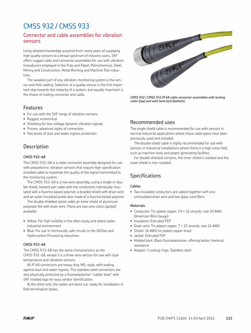
CMSS 932 / CMSS 933Connector and cable assemblies for vibration sensors
Using detailed knowledge acquired from many years of supplying
high quality sensors to a broad spectrum of industry users, SKF
offers rugged cable and connector assemblies for use with vibration
transducers employed in the Pulp and Paper, Petrochemical, Steel,
Mining and Construction, Metal Working and Machine Tool indus-
tries.
The weakest part of any vibration monitoring system is the sen-
sor and field cabling. Selection of a quality sensor is the first impor-
tant step towards the integrity of a system, but equally important is
the choice of mating connector and cable.
Features• For use with the SKF range of vibration sensors
• Rugged, economical
• Shielding for low-voltage dynamic vibration signals
• Proven, advanced styles of connectors
• Two levels of dust and water ingress protection
Description
CMSS 932-68
The CMSS 932-68 is a cable connector assembly designed for use
with piezoelectric vibration sensors that require high specification
shielded cable to maximize the quality of the signal transmitted to
the monitoring system.
The CMSS 932-68 is a two wire assembly, using a single or dou-
ble shield, twisted pair cable with the conductors individually insu-
lated with a fluorine based polymer, a braided shield with drain wire
and an outer insulated jacket also made of a fluorine based polymer.
The double shielded option adds an inner shield of aluminum
polyester foil with drain wire. There are two wire colors (jacket)
available:
• Yellow: For high visibility in the often dusty and debris laden
industrial environment
• Blue: For use in intrinsically safe circuits in the Oil/Gas and
Hydrocarbon Processing industries
CMSS 933-68
The CMSS 933-68 has the same characteristics as the
CMSS 932-68, except it is a three wire version for use with dual
temperature and vibration sensors.
All IP 68 connectors are heavy duty MIL-style, with sealing
against dust and water ingress. The stainless steel connectors are
also physically protected by a fluoroelastomer “rubber boot” with
SKF molded logo for easy vendor identification.
At the other end, the cables are blunt cut, ready for installation in
field termination boxes.
CMSS 932 / CMSS 933 IP 68 cable connector assemblies with locking collar (top) and with twist lock (bottom).
Recommended usesThe single shield cable is recommended for use with sensors in
normal industrial applications where these cable types have been
previously used and installed.
The double shield cable is highly recommended for use with
sensors in industrial installations where there is a high noise field,
such as machine tools and power generating facilities.
For double shielded versions, the inner shield is isolated and the
outer shield is non-isolated.
Specifications
Cables
• Two insulated conductors are cabled together with one
uninsulated drain wire and two glass cord fillers
Materials
• Conductor: Tin plated copper, 19 × 32 strands, size 20 AWG
(American Wire Gauge)
• Insulation: Extruded FEP
• Drain wire: Tin plated copper, 7 × 32 strands, size 24 AWG
• Shield: 36 AWG tin plated copper braid
• Jacket: Extruded FEP
• Molded boot: Black fluoroelastomer, offering better chemical
resistance
• Adaptor / Locking rings: Stainless steel
115PUB CM/P1 11604-14 EN April 2016
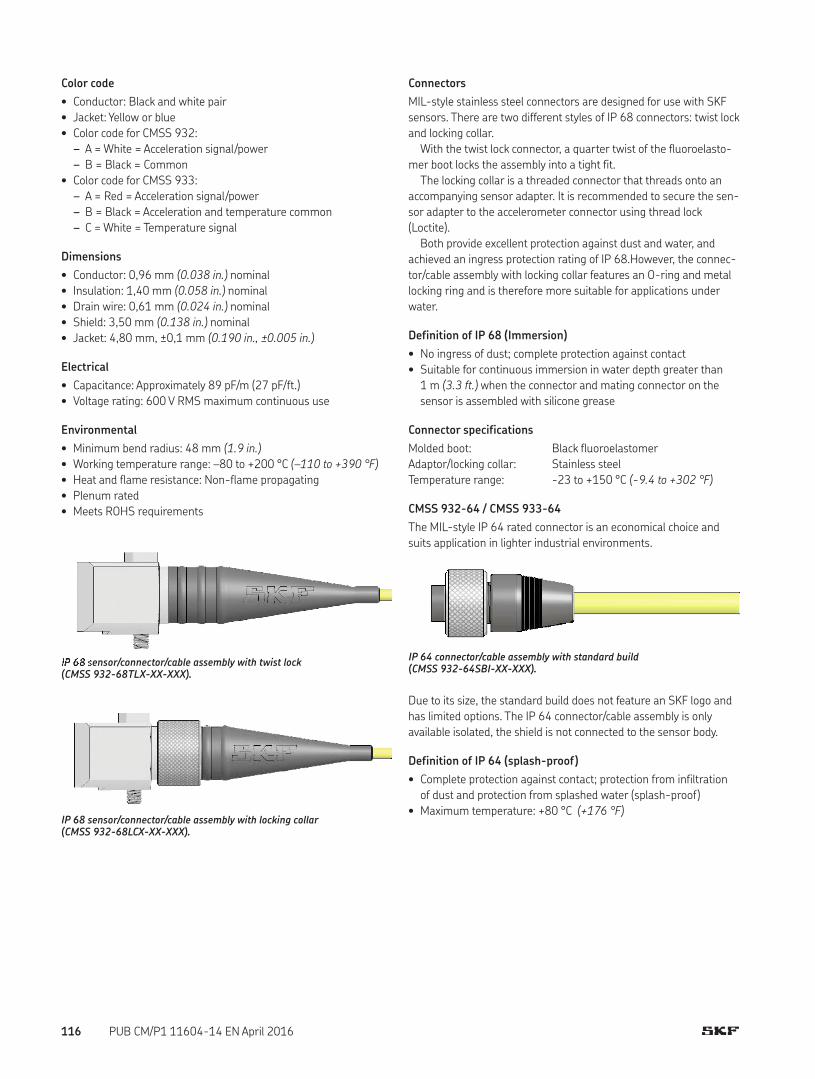
Color code
• Conductor: Black and white pair
• Jacket: Yellow or blue
• Color code for CMSS 932:
– A = White = Acceleration signal/power
– B = Black = Common
• Color code for CMSS 933:
– A = Red = Acceleration signal/power
– B = Black = Acceleration and temperature common
– C = White = Temperature signal
Dimensions
• Conductor: 0,96 mm (0.038 in.) nominal
• Insulation: 1,40 mm (0.058 in.) nominal
• Drain wire: 0,61 mm (0.024 in.) nominal
• Shield: 3,50 mm (0.138 in.) nominal
• Jacket: 4,80 mm, ±0,1 mm (0.190 in., ±0.005 in.)
Electrical
• Capacitance: Approximately 89 pF/m (27 pF/ft.)
• Voltage rating: 600 V RMS maximum continuous use
Environmental
• Minimum bend radius: 48 mm (1.9 in.)
• Working temperature range: –80 to +200 °C (–110 to +390 °F)
• Heat and flame resistance: Non-flame propagating
• Plenum rated
• Meets ROHS requirements
�� �� �ensor/connector/cable assembly with twist lock (CMSS 932-68TLX-XX-XXX).
IP 68 sensor/connector/cable assembly with locking collar (CMSS 932-68LCX-XX-XXX).
Due to its size, the standard build does not feature an SKF logo and
has limited options. The IP 64 connector/cable assembly is only
available isolated, the shield is not connected to the sensor body.
Definition of IP 64 (splash-proof)
• Complete protection against contact; protection from infiltration
of dust and protection from splashed water (splash-proof)
• Maximum temperature: +80 °C (+176 °F)
IP 64 connector/cable assembly with standard build (CMSS 932-64SBI-XX-XXX).
Connectors
MIL-style stainless steel connectors are designed for use with SKF
sensors. There are two different styles of IP 68 connectors: twist lock
and locking collar.
With the twist lock connector, a quarter twist of the fluoroelasto-
mer boot locks the assembly into a tight fit.
The locking collar is a threaded connector that threads onto an
accompanying sensor adapter. It is recommended to secure the sen-
sor adapter to the accelerometer connector using thread lock
(Loctite).
Both provide excellent protection against dust and water, and
achieved an ingress protection rating of IP 68.However, the connec-
tor/cable assembly with locking collar features an O-ring and metal
locking ring and is therefore more suitable for applications under
water.
Definition of IP 68 (Immersion)
• No ingress of dust; complete protection against contact
• Suitable for continuous immersion in water depth greater than
1 m (3.3 ft.) when the connector and mating connector on the
sensor is assembled with silicone grease
Connector specifications
Molded boot: Black fluoroelastomer
Adaptor/locking collar: Stainless steel
Temperature range: -23 to +150 °C (-9.4 to +302 °F)
CMSS 932-64 / CMSS 933-64
The MIL-style IP 64 rated connector is an economical choice and
suits application in lighter industrial environments.
116 PUB CM/P1 11604-14 EN April 2016

Cable assembliesIndustrial two pin accelerometer assemblies for SKF Multilog systems
MIL-style stainless steel connectors are designed for use with SKF
sensors. There are two different styles of IP 68 connectors: an
assembly with a twist lock and an assembly with a locking collar.
The locking collar is a threaded connector that threads onto an
accompanying sensor adapter. It is recommended to secure the
sensor adapter to the accelerometer connector using thread lock
(Loctite).
Both provide excellent protection against dust and water, and both
achieved an ingress protection rating of IP 68. However, the connec-
tor/cable assembly with locking collar features an O-ring and metal
locking ring and is therefore more suitable for applications under
water.
Model number Description Compatible accelerometers
Twist lock cables
• CMSS 780A-IS• CMSS 780A-D2• CMSS 780C• CMSS 780C-M8• CMSS 786A-IS• CMSS 787A-IS• CMSS 787A-M8-IS• CMSS 793-CA• CMSS 793-EE• CMSS 793-FM• CMSS 793L• CMSS 793V• CMSS 793V-CA• CMSS 793V-EE• CMSS 793V-FM• CMSS 797-CA• CMSS 797-EE• CMSS 797L• CMSS 797L-FM• CMSS 797V• CMSS 2100• CMSS 2106• CMSS 2200• CMSS 2200-M8• CMSS 2207
Twist lock, non-isolated
CMSS 932-68TLN-SY-5M
CMSS 932-68TLN-SY-10M
CMSS 932-68TLN-SY-10M
Two wire, IP 68 connector, twist lock, non-isolated, single shield, yellow cable, 5 m (16.4 ft.) lengthTwo wire, IP 68 connector, twist lock, non-isolated, single shield, yellow cable, 10 m (32.8 ft.) lengthTwo wire, IP 68 connector, twist lock, non-isolated, single shield, yellow cable, 20 m (65.6 ft.) length
Twist lock, isolated
CMSS 932-68TLI-SY-5M
CMSS 932-68TLI-SY-10M
CMSS 932-68TLI-SY-10M
Two wire, IP 68 connector, twist lock, isolated, single shield,yellow cable, 5 m (16.4 ft.) lengthTwo wire, IP 68 connector, twist lock, isolated, single shield,yellow cable, 10 m (32.8 ft.) lengthTwo wire, IP 68 connector, twist lock, isolated, single shield,yellow cable, 20 m (65.6 ft.) length
Locking collar cables
Locking collar, non-isolated
CMSS 932-68LCN-SY-5M
CMSS 932-68LCN-SY-10M
CMSS 932-68LCN-SY-10M
Two wire, IP 68 connector, locking collar, non-isolated, single shield, yellow cable, 5 m (16.4 ft.) lengthTwo wire, IP 68 connector, locking collar, non-isolated, single shield, yellow cable, 10 m (32.8 ft.) lengthTwo wire, IP 68 connector, locking collar, non-isolated, single shield, yellow cable, 20 m (65.6 ft.) length
Locking collar, isolated
CMSS 932-68LCI-SY-5M
CMSS 932-68LCI-SY-10M
CMSS 932-68LCI-SY-10M
Two wire, IP 68 connector, locking collar, isolated, single shield, yellow cable, 5 m (16.4 ft.) lengthTwo wire, IP 68 connector, locking collar, isolated, single shield, yellow cable, 10 m (32.8 ft.) lengthTwo wire, IP 68 connector, locking collar, isolated, single shield, yellow cable, 20 m (65.6 ft.) length
117PUB CM/P1 11604-14 EN April 2016

IP 68 rated cable/connector assembly – industrial
Ordering information
CMSS 932 Two-wire twisted pair cable / two-pin connector assembly. CMSS 933 Three-wire twisted triad cable / three-pin connector assembly.
CMSS 93a–68bbc-de-fff
a: Wire23
Two-wire twisted pair, two-pin connectorThree-wire twisted triad, three-pin connector
68: IP 68 connector (immersion)
bb: Lock typeTLLC
Twist lockLocking collar
c: Isolated/Non-isolatedIN
Isolated (must use single shielded)Non-isolated
d: ShieldDS
Double shielded (must use non-isolated)Single shielded
e: JacketYB
Yellow jacketBlue jacket
fff: Length5M10M20MXXM
Length: 5 meters (16.4 ft.)Length: 10 m (32.8 ft.)Length: 20 m (65.6 ft.)Length: Specify XX meters, in 5 m increments
Note: Isolated connectors cannot be selected with double shielded
cables (e.g., part number CMSS 932-68LCI-DY-XXM is not valid).
As such, if a double shielded cable is required (shield = D), select a
non-insolated connector (non-isolated = N); for example:
• CMSS 932-68LCN-DY-5M
If a isolated connector is required (isolated = I), select a single
shielded cable (shield = S); for example:
• CMSS 932-68LCI-SY-5M
Double shielded cable should be grounded on both sides: the instru-
ment side and the sensor side (through the machine). If an isolated
connector is selected with a double shielded cable, the sensor side
will be cut off and never connected to the sensor ground.
118 PUB CM/P1 11604-14 EN April 2016

Cable assembliesEconomical two pin accelerometer assemblies
The MIL-style IP 64 rated connector is an economical choice and
suits applications in lighter industrial environments. Due to its size,
the standard build does not feature an SKF logo and has limited
options. The IP 64 connector/cable assembly is only available
isolated; the shield is not connected to the sensor body.
Model number Description Compatible accelerometers
Standard build cables • CMSS 780A-IS• CMSS 780A-D2• CMSS 780C• CMSS 780C-M8• CMSS 786A-IS• CMSS 787A-IS• CMSS 787A-M8-IS• CMSS 793-CA• CMSS 793-EE• CMSS 793-FM• CMSS 793L• CMSS 793V• CMSS 793V-CA• CMSS 793V-EE• CMSS 793V-FM• CMSS 797-CA• CMSS 797-EE• CMSS 797L• CMSS 797L-FM• CMSS 797V• CMSS 2100• CMSS 2106• CMSS 2200• CMSS 2200-M8• CMSS 2207
Standard build, isolated
CMSS 932-64SBI-SY-5M
CMSS 932-64SBI-SY-10M
CMSS 932-64SBI-SY-10M
Two wire, IP 64 connector, standard build, isolated, single shield, yellow cable, 5 m (16.4 ft.) lengthTwo wire, IP 64 connector, standard build, isolated, single shield, yellow cable, 10 m (32.8 ft.) lengthTwo wire, IP 64 connector, standard build, isolated, single shield, yellow cable, 20 m (65.6 ft.) length
Longer cable lengths are available upon request. Please contact your SKF Sales Representative.
119PUB CM/P1 11604-14 EN April 2016
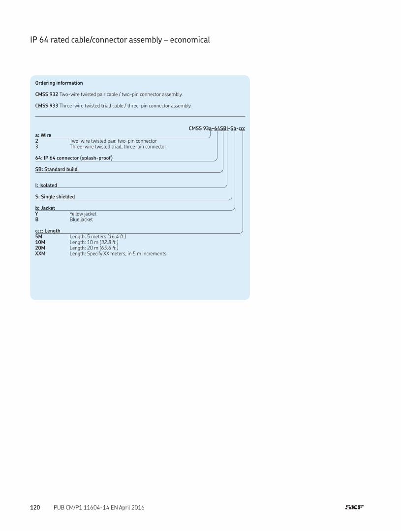
IP 64 rated cable/connector assembly – economical
Ordering information
CMSS 932 Two-wire twisted pair cable / two-pin connector assembly. CMSS 933 Three-wire twisted triad cable / three-pin connector assembly.
CMSS 93a–64SBI-Sb-ccc
a: Wire23
Two-wire twisted pair, two-pin connectorThree-wire twisted triad, three-pin connector
64: IP 64 connector (splash-proof)
SB: Standard build
I: Isolated
S: Single shielded
b: JacketYB
Yellow jacketBlue jacket
ccc: Length5M10M20MXXM
Length: 5 meters (16.4 ft.)Length: 10 m (32.8 ft.)Length: 20 m (65.6 ft.)Length: Specify XX meters, in 5 m increments
120 PUB CM/P1 11604-14 EN April 2016
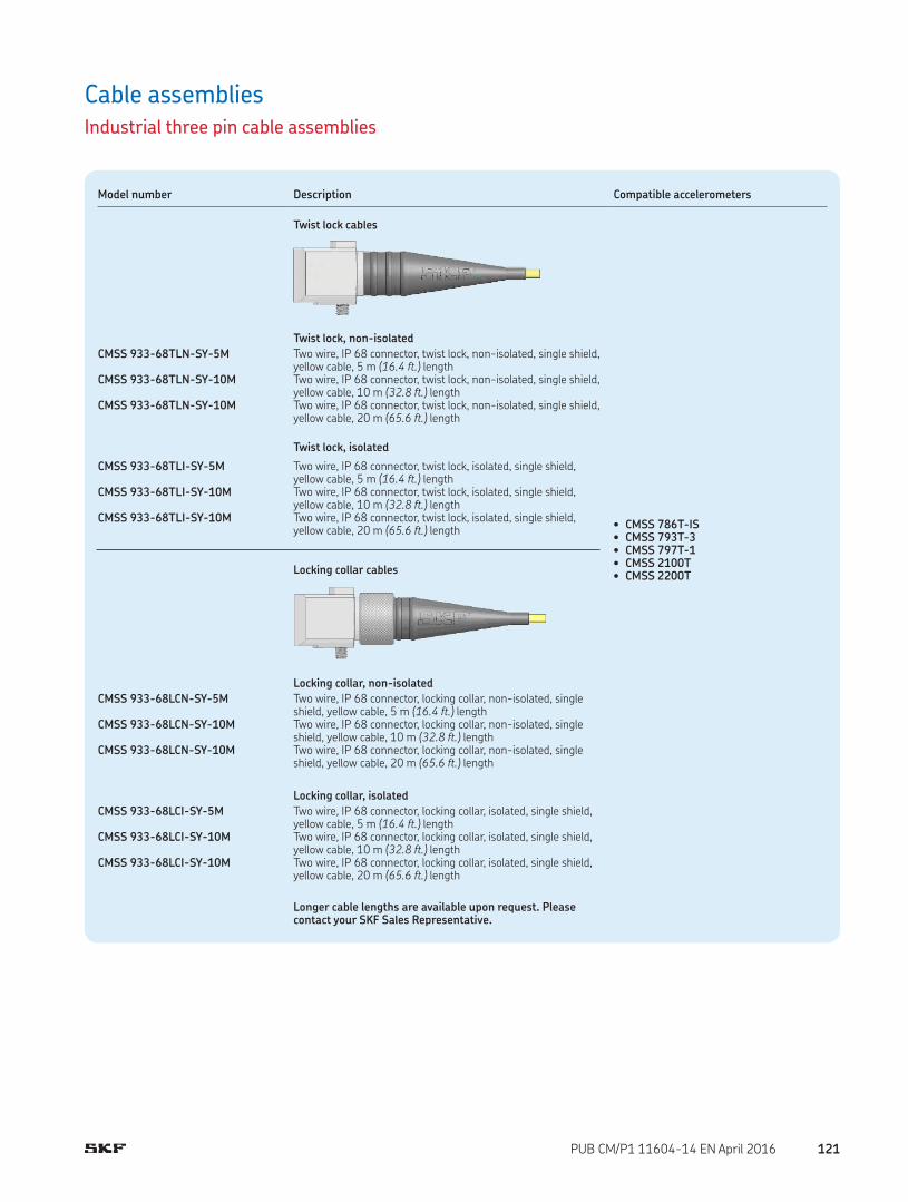
Cable assembliesIndustrial three pin cable assemblies
Model number Description Compatible accelerometers
Twist lock cables
• CMSS 786T-IS• CMSS 793T-3• CMSS 797T-1• CMSS 2100T• CMSS 2200T
Twist lock, non-isolated
CMSS 933-68TLN-SY-5M
CMSS 933-68TLN-SY-10M
CMSS 933-68TLN-SY-10M
Two wire, IP 68 connector, twist lock, non-isolated, single shield, yellow cable, 5 m (16.4 ft.) lengthTwo wire, IP 68 connector, twist lock, non-isolated, single shield, yellow cable, 10 m (32.8 ft.) lengthTwo wire, IP 68 connector, twist lock, non-isolated, single shield, yellow cable, 20 m (65.6 ft.) length
Twist lock, isolated
CMSS 933-68TLI-SY-5M
CMSS 933-68TLI-SY-10M
CMSS 933-68TLI-SY-10M
Two wire, IP 68 connector, twist lock, isolated, single shield,yellow cable, 5 m (16.4 ft.) lengthTwo wire, IP 68 connector, twist lock, isolated, single shield,yellow cable, 10 m (32.8 ft.) lengthTwo wire, IP 68 connector, twist lock, isolated, single shield,yellow cable, 20 m (65.6 ft.) length
Locking collar cables
Locking collar, non-isolated
CMSS 933-68LCN-SY-5M
CMSS 933-68LCN-SY-10M
CMSS 933-68LCN-SY-10M
Two wire, IP 68 connector, locking collar, non-isolated, single shield, yellow cable, 5 m (16.4 ft.) lengthTwo wire, IP 68 connector, locking collar, non-isolated, single shield, yellow cable, 10 m (32.8 ft.) lengthTwo wire, IP 68 connector, locking collar, non-isolated, single shield, yellow cable, 20 m (65.6 ft.) length
Locking collar, isolated
CMSS 933-68LCI-SY-5M
CMSS 933-68LCI-SY-10M
CMSS 933-68LCI-SY-10M
Two wire, IP 68 connector, locking collar, isolated, single shield, yellow cable, 5 m (16.4 ft.) lengthTwo wire, IP 68 connector, locking collar, isolated, single shield, yellow cable, 10 m (32.8 ft.) lengthTwo wire, IP 68 connector, locking collar, isolated, single shield, yellow cable, 20 m (65.6 ft.) length
Longer cable lengths are available upon request. Please contact your SKF Sales Representative.
121PUB CM/P1 11604-14 EN April 2016
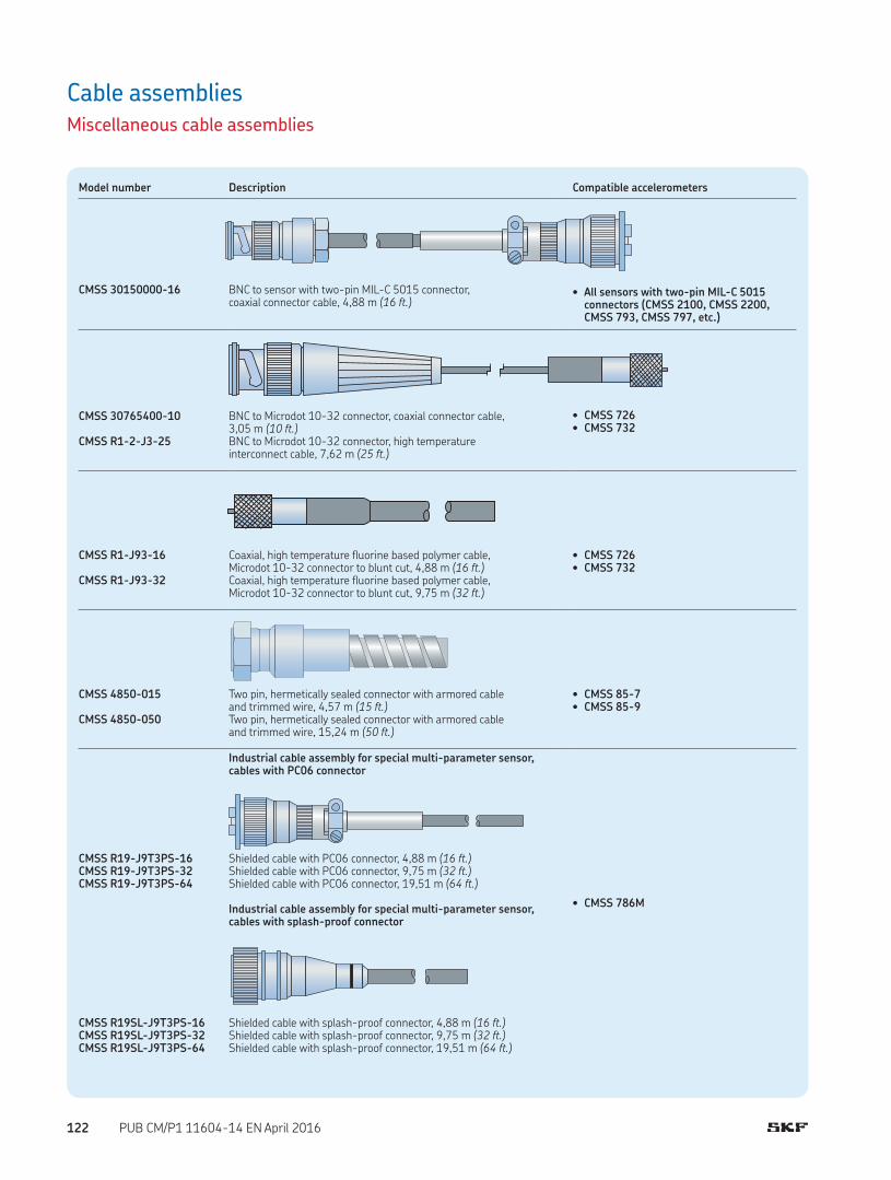
Cable assembliesMiscellaneous cable assemblies
Model number Description Compatible accelerometers
• All sensors with two-pin MIL-C 5015 connectors (CMSS 2100, CMSS 2200, CMSS 793, CMSS 797, etc.)
CMSS 30150000-16 BNC to sensor with two-pin MIL-C 5015 connector,coaxial connector cable, 4,88 m (16 ft.)
• CMSS 726• CMSS 732
CMSS 30765400-10 BNC to Microdot 10-32 connector, coaxial connector cable, 3,05 m (10 ft.)
CMSS R1-2-J3-25 BNC to Microdot 10-32 connector, high temperatureinterconnect cable, 7,62 m (25 ft.)
• CMSS 726• CMSS 732
CMSS R1-J93-16 Coaxial, high temperature fluorine based polymer cable,Microdot 10-32 connector to blunt cut, 4,88 m (16 ft.)
CMSS R1-J93-32 Coaxial, high temperature fluorine based polymer cable,Microdot 10-32 connector to blunt cut, 9,75 m (32 ft.)
• CMSS 85-7• CMSS 85-9
CMSS 4850-015 Two pin, hermetically sealed connector with armored cableand trimmed wire, 4,57 m (15 ft.)
CMSS 4850-050 Two pin, hermetically sealed connector with armored cableand trimmed wire, 15,24 m (50 ft.)
Industrial cable assembly for special multi-parameter sensor, cables with PC06 connector
• CMSS 786M
CMSS R19-J9T3PS-16 Shielded cable with PC06 connector, 4,88 m (16 ft.)CMSS R19-J9T3PS-32 Shielded cable with PC06 connector, 9,75 m (32 ft.)CMSS R19-J9T3PS-64 Shielded cable with PC06 connector, 19,51 m (64 ft.)
Industrial cable assembly for special multi-parameter sensor, cables with splash-proof connector
CMSS R19SL-J9T3PS-16 Shielded cable with splash-proof connector, 4,88 m (16 ft.)CMSS R19SL-J9T3PS-32 Shielded cable with splash-proof connector, 9,75 m (32 ft.)CMSS R19SL-J9T3PS-64 Shielded cable with splash-proof connector, 19,51 m (64 ft.)
122 PUB CM/P1 11604-14 EN April 2016

Connectors and toolkitsFor on-site cable fabrication
Model number Description
Connector packs for cables with a twist lock connector
For CMSS 932 series
CMSS 932-68TL-1 Connector pack for CMSS 932 series cable, two pin, IP 68, twist lock, isolated and non-isolated, single and double shield, quantity one
CMSS 932-68TL-10 Connector pack for CMSS 932 series cable, two pin, IP 68, twist lock, isolated and non-isolated, single and double shield, quantity 10
CMSS 932-68TL-50 Connector pack for CMSS 932 series cable, two pin, IP 68, twist lock, isolated and non-isolated, single and double shield, quantity 50
For CMSS 933 seriesCMSS 933-68TL-1 Connector pack for CMSS 933 series cable, three pin, IP 68, twist lock, isolated and non-isolated, single shield,
quantity oneCMSS 933-68TL-10 Connector pack for CMSS 933 series cable, three pin, IP 68, twist lock, isolated and non-isolated, single shield,
quantity 10CMSS 933-68TL-50 Connector pack for CMSS 933 series cable, three pin, IP 68, twist lock, isolated and non-isolated, single shield,
quantity 50
Connector packs for cables with a locking collar connector
For CMSS 932 seriesCMSS 932-68LC-1 Connector pack for CMSS 932 series cable, two pin, IP 68, locking collar, isolated and non-isolated, single and double
shield, quantity oneCMSS 932-68LC-10 Connector pack for CMSS 932 series cable, two pin, IP 68, locking collar, isolated and non-isolated, single and double
shield, quantity 10CMSS 932-68LC-50 Connector pack for CMSS 932 series cable, two pin, IP 68, locking collar, isolated and non-isolated, single and double
shield, quantity 50
For CMSS 933 seriesCMSS 933-68LC-1 Connector pack for CMSS 933 series cable, three pin, IP 68, locking collar, isolated and non-isolated, single shield,
quantity oneCMSS 933-68LC-10 Connector pack for CMSS 933 series cable, three pin, IP 68, locking collar, isolated and non-isolated, single shield,
quantity 10CMSS 933-68LC-50 Connector pack for CMSS 933 series cable, three pin, IP 68, locking collar, isolated and non-isolated, single shield,
quantity 50
Model number Description Compatible accelerometers
• CMSS 2100-M12CMSS RM12-ST-J10-10
CMSS RM12-ST-J10-16
CMSS RM12-ST-J10-32
CMSS RM12-ST-J10-64
Cable connector assembly with M12 connector, IP 68, two-wire cable, isolated, single shield, grey, 3,05 m (10 ft.)Cable connector assembly with M12 connector, IP 68, two-wire cable, isolated, single shield, grey, 4,88 m (16 ft.)Cable connector assembly with M12 connector, IP 68, two-wire cable, isolated, single shield, grey, 9,75 m (32 ft.)Cable connector assembly with M12 connector, IP 68, two-wire cable, isolated, single shield, grey, 19,51 m (64 ft.)
123PUB CM/P1 11604-14 EN April 2016

Connectors and toolkitsFor on-site cable fabrication (continued)
Model number Description
CMSS 930-68-K Toolkit for field installationToolkit for field installation for CMSS 93x series cable, IP 68 connectors, single and double shield (excludes connectors), for 25 to 50 connectors
Each toolkit contains:
• Crimp tool• Crimp tool positioner• Crimp tool frame• Exacto knife• Exacto knife blades (15)• Scissors• Wire stripper• High temperature epoxy (3 pack) (must use within two months)• Epoxy mix applicator gun• Metal socket insertion tool• Plastic socket insertion tool (2)• Epoxy mixing plunger• Epoxy nozzle (static mixing tubes) (10)
Replenishable accessories
CMAC 930-01 Epoxy nozzle (static mixing tube)CMAC 930-02 High temperature epoxy (must use within two months)CMAC 930-03 Plastic socket insertion tool
Epoxy nozzle (static mixing tubes), 10 each
High temperature epoxy, 3 each
Epoxy applicator gun with 4:1 plunger
15 blades
Crimp tool
Exacto knife
Wire stripper
Metal socket insertion tool
Plastic socket insertion tool, 2 each
Scissors
Crimp frame tool and crimp positioner tool
CMSS 930-68-K Toolkit for field installation
124 PUB CM/P1 11604-14 EN April 2016

Mounting hardwareAccelerometer / Velocity sensor mounting hardware
Model number Description
CMAC 230 Threaded mounting stud (1/4-28 to 1/4-28)
• Flanged sensor mounting stud, 1/4-28 thread on both sides• Material: Stainless steel• Recommended mounting torque: 2,9 Nm (24 in. lbs.)• Frequency response: Proper mounting on clean flat surface can achieve the specified
frequency response of sensor
Ordering information:
• CMAC 230-10 Threaded mounting studs (1/4-28 to 1/4-28), stainless steel, 10-pack• CMAC 230-50 Threaded mounting studs (1/4-28 to 1/4-28), stainless steel, 50-pack
CMAC 231 Adapter mounting stud (1/4-28 to M8)
• Flanged sensor mounting stud, adapts 1/4-28 threads to M8 thread• Material: Stainless steel• Recommended mounting torque: 2,9 Nm (24 in. lbs.)• Frequency response: Proper mounting on clean flat surface can achieve the specified
frequency response of sensor
Ordering information:
• CMAC 231-10 Adapter mounting studs (1/4-28 to M8), stainless steel, 10-pack• CMAC 231-50 Adapter mounting studs (1/4-28 to M8), stainless steel, 50-pack
CMSS 30168703 Adapter mounting stud (1/4-28 to M6)
• Flanged sensor mounting stud, adapts 1/4-28 tapped threads to M6 thread• Material: Stainless steel• Recommended mounting torque: 2,9 Nm (24 in. lbs.)• Frequency response: Proper mounting on clean flat surface can achieve the specified
frequency response of sensor
CMSS 30205300 Mounting stud (1/4-28 to 10-32)
• Flanged sensor mounting stud, adapts 1/4-28 tapped threads to 10-32 thread• Material: Stainless steel• Recommended mounting torque: 2,3 Nm (20 in. lbs.)• Frequency response: Proper mounting on clean flat surface can achieve the specified
frequency response of sensor
4,7 mm (0.19 in.)
1/4-28
M8 × 1,25
8,3 mm (0.33 in.)
9,1 mm (0.36 in.)
4,6 mm (0.18 in.)
1/4-28
1/4-28
4,7 mm (0.19 in.)
4,7 mm (0.19 in.)
M6 × 1,00
1/4-28
Sensor end 10-32
Structure end 1/4-28
8,1 mm (0.32 in.)
3,0 mm (0.12 in.)
125PUB CM/P1 11604-14 EN April 2016

Mounting hardwareAccelerometer / Velocity sensor mounting hardware (continued)
Model number Description
CMSS 12105-03
CMSS 12105-01
Metric thread, socket head, captive mounting bolt M6 × 1.0 (37 mm overall), black oxide finish, for ring-mode superior accelerometers CMSS 2207, CMSS 797, CMSS 797-CA/EE/FM, CMSS 797L, CMSS 797L-FM, CMSS 797T-1, CMSS 797V
Imperial thread, socket head, captive mounting bolt 1/4-28 (1.40 in. overall), 18-8 stainless steel, for ring-mode superior accelerometers CMSS 2207, CMSS 797, CMSS 797-CA/EE/FM, CMSS 797L, CMSS 797L-FM, CMSS 797T-1, CMSS 797V
CMSS 11714-05
CMSS 11714-04
Metric thread, socket head, captive mounting bolt M6 × 1.0 (32 mm overall), black oxide finish, for standard side-exit accelerometers CMSS 2200, CMSS 2200T, CMSS 787A-D2, CMSS 787A-IS
Imperial thread, socket head, captive mounting bolt 1/4-28 (1.25 in. overall), 18-8 stainless steel, for standard side-exit accelerometers CMSS 2200, CMSS 2200T, CMSS 787A-D2, CMSS 787A-IS
CMSS 11714-06 Metric thread, socket head, captive mounting bolt M8 × 1.25 (33 mm overall), black oxide finish, for standard side-exit accelerometers CMSS 2200-M8, CMSS 787A-M8-D2, CMSS 787A-M8-IS
CMSS 910M Cementing stud with 1/4-28 male
• Cementing studs for sensors with 1/4-28 tapped threads• Material: Stainless steel• Recommended mounting torque: 2,9 Nm (24 in. lbs.)• Frequency response: Flat up to about 80% of the specified response value using
epoxy or similar cement; flat up to about 30% of the specified response value using double-sided tape
Note: To avoid sensor damage, always remove the sensor from the cementing stud first, then remove the stud from the surface by means of a wrench using the flats provided.
Recommended with Loctite 454 adhesive gel (not included).
22,4 mm (0.88 in.)
11,2 mm (0.44 in.)
25,4 mm (1.00 in.) diameter
10,2 mm (0.40 in.)
5,6 mm (0.22 in.)
4,6 mm (0.18 in.)
1/4-28
126 PUB CM/P1 11604-14 EN April 2016

Mounting hardwareAccelerometer / Velocity sensor mounting hardware (continued)
Model number Description
CMSS 910F Cementing stud with 1/4-28 female
• Cementing studs for sensors requiring 1/4-28 tapped mounting threads (see page 139 for adapters to M6, M8 and 10-32 thread accelerometers); includes key notch for consistent triaxial axis orientation
• Material: Stainless steel• Recommended mounting torque: 2,9 Nm (24 in. lbs.)• Frequency response: Flat up to about 80% of the specified response value using
epoxy or similar cement; flat up to about 30% of the specified response value using double-sided tape
Note: To avoid sensor damage, always remove the sensor from the cementing stud first, then remove the stud from the surface by means of a wrench using the flats provided.
Recommended with Loctite 454 adhesive gel (not included).
CMSS 910QDB1CMSS 910QDP1CMSS 910QDP2
Quick connect/disconnect sensor mounting pads
Mounting pads allow vibration technicians using such instruments as the SKF Microlog on walkaround routes to quickly mount vibration sensors in less than one turn. This quick mount design results in a decrease in mounting time as compared to the older style threaded stud mounting pads.
Key benefits:• Decreased sensor mounting time by 90%• Eliminates wrist fatigue from repetitive twisting• Combines ease and speed of a magnet mount with the
accuracy and repeatability of a permanent mount• Ensures the repeatable, reliable vibration data of a
permanently mounted sensor• Prevents cable twisting• Upgrades existing installations
Features:• Constructed of corrosion resistant 316 stainless steel• Convenient cement mounting capability• Accepts all 1/4-28 compatible vibration sensors, including SKF's low profile models• Compatible with existing 1/4-28 stud mount installations• Easily removed to upgrade to permanent mount allowing the sensor to be directly
attached to the same measuring point
CMSS 910QDB1 Quick connect adapter sensor base
• The CMSS 910QDB1 attaches easily to 1/4-28 compatible sensors• In walkaround data collection, the sensor can be attached in less than one turn to any
of the quick connect/disconnect mounting pads• The CMSS 910QDB1 can remain on the sensor or be removed and reattached to
other popular SKF vibration sensors
22,4 mm (0.88 in.)
12,7 mm (0.50 in.)
25,4 mm (1.00 in.) diameter
4,0 mm (0.16 in.)
radius key notch
6,4 mm (0.25 in.)
1/4-28
127PUB CM/P1 11604-14 EN April 2016

Mounting hardwareAccelerometer / Velocity sensor mounting hardware (continued)
Model number Description
CMSS 910QDP1 Quick connect, threaded stud mounting pad
• The CMSS 910QDP1 is stud mounted to the measuring point or attached to an existing 1/4-28 stud
• Easy conversion to permanently mounted sensors• Once the CMSS 910QDP1 is mounted, conversion to permanently mounted sensors
is quick and easy• By simply removing the pad and attaching an SKF vibration sensor to the existing
1/4-28 stud, sensor location and vibration data history remains reliable
CMSS 910QDP2 Quick connect, cement mounting pad
• The CMSS 910QDP2 is epoxied to the measuring point• Removable for upgrading to permanently mounted sensors• When upgrading to permanently mounted sensors, the cement pad can easily be
removed to allow a stud mounted sensor to be installed in the location
12,7 mm (0.50 in.)
25,4 mm (1.00 in.)
1/4-28 tapped hole
25,4 mm (1.00 in.)
12,7 mm (0.50 in.)
128 PUB CM/P1 11604-14 EN April 2016
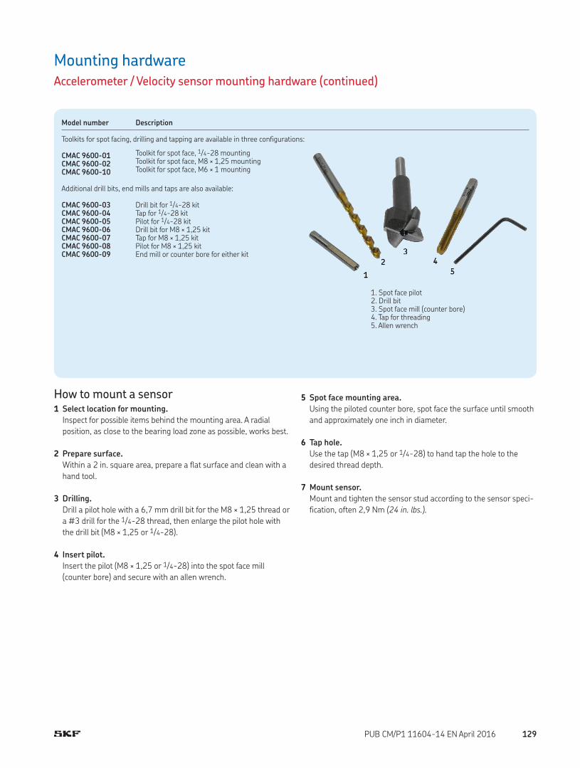
Mounting hardwareAccelerometer / Velocity sensor mounting hardware (continued)
Model number Description
Toolkits for spot facing, drilling and tapping are available in three configurations:
CMAC 9600-01CMAC 9600-02CMAC 9600-10
Toolkit for spot face, 1/4-28 mountingToolkit for spot face, M8 × 1,25 mountingToolkit for spot face, M6 × 1 mounting
Additional drill bits, end mills and taps are also available:
CMAC 9600-03CMAC 9600-04CMAC 9600-05CMAC 9600-06CMAC 9600-07CMAC 9600-08CMAC 9600-09
Drill bit for 1/4-28 kitTap for 1/4-28 kitPilot for 1/4-28 kitDrill bit for M8 × 1,25 kitTap for M8 × 1,25 kitPilot for M8 × 1,25 kitEnd mill or counter bore for either kit
1. Spot face pilot2. Drill bit3. Spot face mill (counter bore)4. Tap for threading5. Allen wrench
How to mount a sensor1 Select location for mounting.
Inspect for possible items behind the mounting area. A radial
position, as close to the bearing load zone as possible, works best.
2 Prepare surface.
Within a 2 in. square area, prepare a flat surface and clean with a
hand tool.
3 Drilling.
Drill a pilot hole with a 6,7 mm drill bit for the M8 × 1,25 thread or
a #3 drill for the 1/4-28 thread, then enlarge the pilot hole with
the drill bit (M8 × 1,25 or 1/4-28).
4 Insert pilot.
Insert the pilot (M8 × 1,25 or 1/4-28) into the spot face mill
(counter bore) and secure with an allen wrench.
5 Spot face mounting area.
Using the piloted counter bore, spot face the surface until smooth
and approximately one inch in diameter.
6 Tap hole.
Use the tap (M8 × 1,25 or 1/4-28) to hand tap the hole to the
desired thread depth.
7 Mount sensor.
Mount and tighten the sensor stud according to the sensor speci-
fication, often 2,9 Nm (24 in. lbs.).
129PUB CM/P1 11604-14 EN April 2016

Magnetic bases for curved surfaces (CMSS 908-MD and CMSS 909-HD)
Models CMSS 908-MD and CMSS 909-HD are designed in a two-pole configuration for industrial vibration monitoring applications where flat surfaces are rarely found. Each magnet is supplied with a 1/4-28 mounting stud to allow compatibility with most SKF transducers. Note: Two-pole magnet bases are recommended for low-frequency measurements only, and only for applications where other mounting methods are now practical.
Model number Description
CMSS 908-MDMedium-duty magnetic base for use in moderate conditions
• Material: Stainless steel• Pull strength: 23 kg (50 lbs.)• Mounting hole: 1/4-28• Dimensions: 19,0 mm (0.75 in.) height × 35,6 mm (1.40 in.) diameter
CMSS 909-HD
High-strength magnet base for high duty. Features alignment holes for triaxial sensors.
• Material: Rare earth neodymium, mounted in a stainless steel housing with steel poles.
• Frequency response: Flat up to about 10% of resonance frequency (6,6 kHz)• Pull strength: Approximately 34 kg (75 lbs.) of force• Mounting: 1/4-28 hole• Dimensions: 20,52 mm (0,808 in.) height × 38,35 mm (1.51 in.) diameter
Magnet base for flat surfaces
CMSS 909-RE
Rare earth flat-bottom magnetic base for flat surfaces
• Material: Rare earth neodymium, mounted in a stainless steel housing• Frequency response: Flat up to about 20% of resonance frequency (8,4 kHz)• Pull strength: Approximately 18,1 kg (40 lbs.)• Mounting hole: 1/4-28 hole• Dimensions: 10,41 mm (0,410 in.) height × 25,65 mm (1,010 in.) diameter
Magnet base for smaller sensors (CMSS 732A)
CMSS B13
Rare earth two-pole magnet with knurled gripping surface
• Pull strength: Approximately 16 kg (35 lbs.)• Mounting hole: 1/4-28 hole (studs and adapter available)• Dimensions: 17,53 mm (0,69 in.) height × 25,65 mm (1,01 in.) diameter
1/4-28 mounting hole
19,0 mm
(0,75 in.)
35,6 mm
(1,40 in.)
19,05 mm
(0,750 in.)
38.35 mm(1,510 in.)
2,03 mm
(0,08 in.)
25.65 mm(1,010 in.)
10.41 mm(0,410 in.)
25.65 mm(1,010 in.)
17,53 mm(0,69 in.)
2,03 mm(0,08 in.)
Mounting hardwareMagnetic bases
130 PUB CM/P1 11604-14 EN April 2016

Mounting hardwareCMSS 50042300Case mounted transducer housing
The CMSS 50042300 case mounted transducer housing provides
physical and environmental protection for the CMSS 766,
CMSS 786 and CMSS 793 series seismic sensors. The housing is
used in installations where the pickup can be subject to possible
damage from adverse conditions. This housing meets API 670 stan-
dards when properly installed.
The mounting kit includes a dome cover, mounting base with a 3/4 in. conduit connection, neoprene gasket, mounting screws,
washers and a 1/2 in. NPT reducing bushing.
Note: The seismic sensor must be ordered separately.
InstallationThe housing is compatible with 1/2 in. and 3/4 in. flex, EMT and rigid
conduit.
1 Selector prepare the flat surface for installation of the protective
housing at the sensor location.
Note: If the machine housing is radiused, surface the mounting area flat to maintain a full 360° gasket seal in the radiused plane and install with a minimum of two mounting screws 180° apart.
2 Drill center for 7/32 in. pilot hole 0.313 in. deep and spot face
1.0 in. surface to 0.030 in. deep to 63 RMS finish for direct
mounted sensor installation. Tap center of the spot faced surface
for 1/4-28 threads.
Note: A 63 RMS finish cannot normally be achieved using portable power tools, typically requiring the machine housing to be removed and milled to the proper specifications in a machine shop. An alternative is to install a mounting pad with the proper finish, such as Part Number 70005050.
3 Drill and tap four equally spaced 1/4-20 UNC-2B × 10,0 mm
(0.375 in.) deep on a 42,0 mm (1.62 in.) diameter bolt circle.
4 Place the neoprene gasket in place.
5 Install the housing base over the gasket, orienting the conduit
outlet as required for your installation. Secure the housing base
with four 1/4-20 UNC cap screws and lockwashers (provided).
6 Screw the transducer into the center mounting hole. Do not
exceed the manufacturer’s torque recommendations (23 Nm).
7 Place the O-ring on the dome cover and screw the dome cover
into the housing base until finger-tight.
8 Optional 3/4 to 1/2 in. conduit reducing bushings can now be
installed.
Installation steps
4
5
6
7
8
131PUB CM/P1 11604-14 EN April 2016

Ordering information
CMSS 50042300 Case mounted transducer housing.
Dimensions
31,7 mm (1.25 in.) diameter ±1,27 mm (±0.05 in.)
7,1 mm (0.28 in.) diameter four places equally spaced on 41,5 mm (1.62 in.) diameter ±0,25 mm (±0.01 in.)
Neoprene gasket
86,0 mm (3.38 in.)
63,5 mm (2.50 in.)
42,0 mm (1.65 in.) 38,0 mm
(1.50 in.)
120,0 mm (4.75 in.)
3/4 in. NPT
132 PUB CM/P1 11604-14 EN April 2016

CMSS 30266101Transducer housing, 3/4 in. NPT with 1/4-28 thread
Ordering information
CMSS 30266101 Transducer housing, 3/4 in. NPT mounting with 1/4-28 thread.
The transducer housing encloses a seismic transducer, protecting it
from mechanical damage and shielding it and the electrical connec-
tions from water spray and other environmental hazards. The trans-
ducer mounts to the 1/4-28 mounting hole provided on the top of
the mounting adapter (provided).
Note: The operating frequency response of an accelerometer may be affect-ed when mounted in this housing due to the change in mass configuration. It is not recommended for higher speed or light case to rotor weight machinery applications (e.g., gearbox, gas turbines, etc.).
Dimensions
120,7 mm (4.75 in.)
149,1 mm (5.87 in.)
Mounting adapter
133PUB CM/P1 11604-14 EN April 2016

Product index
CMAC 230 . . . . . . . . . . . . . . . . . . . . . . . . .Threaded mounting stud (1/4-28 to 1/4-28) . . . . . . . . . . . . . . . . . . . . . . . . . . . . . . . . . . . . . . . . . . . . . . . . . . . 137
CMAC 231 . . . . . . . . . . . . . . . . . . . . . . . . .Adapter mounting stud (1/4-28 to M8) . . . . . . . . . . . . . . . . . . . . . . . . . . . . . . . . . . . . . . . . . . . . . . . . . . . . . . . 137
CMAC 930 series . . . . . . . . . . . . . . . . . . .Replenishable accessories for CMSS 930-68-K toolkit for field installation . . . . . . . . . . . . . . . . . . . . . . . . . . . 136
CMAC 4370-K. . . . . . . . . . . . . . . . . . . . . .Triax accelerometer kit . . . . . . . . . . . . . . . . . . . . . . . . . . . . . . . . . . . . . . . . . . . . . . . . . . . . . . . . . . . . . . . . . . . 92
CMAC 9600 series . . . . . . . . . . . . . . . . . .Tools and toolkits for spot facing, drilling and tapping . . . . . . . . . . . . . . . . . . . . . . . . . . . . . . . . . . . . . . . . . . . . 141
CMPT 2310. . . . . . . . . . . . . . . . . . . . . . . .Accelerometer for mining industry, integral, braided cable, side exit . . . . . . . . . . . . . . . . . . . . . . . . . . . . . . . . . 41
CMPT 2310A . . . . . . . . . . . . . . . . . . . . . .Mining Group 1 Intrinsically Safe accelerometer (IEXEcx / ATEX certified) . . . . . . . . . . . . . . . . . . . . . . . . . . . . . 76
CMPT 2310AC . . . . . . . . . . . . . . . . . . . . .Mining Group 1 Intrinsically Safe accelerometer (IEXEcx ITA Australia certified) . . . . . . . . . . . . . . . . . . . . . . . . 78
CMPT 2310ACT . . . . . . . . . . . . . . . . . . . .Mining Group 1 Intrinsically Safe accelerometer (IEXEcx ITA Australia certified) . . . . . . . . . . . . . . . . . . . . . . . . 78
CMPT 2310T . . . . . . . . . . . . . . . . . . . . . .Sensor for mining industry, side exit, acceleration and temperature . . . . . . . . . . . . . . . . . . . . . . . . . . . . . . . . . 61
CMPT 2310TA . . . . . . . . . . . . . . . . . . . . .Mining Group 1 Intrinsically Safe accelerometer (IEXEcx / ATEX certified) . . . . . . . . . . . . . . . . . . . . . . . . . . . . . 76
CMPT 2323. . . . . . . . . . . . . . . . . . . . . . . .Accelerometer for mining industry, integral, braided cable, side exit . . . . . . . . . . . . . . . . . . . . . . . . . . . . . . . . . 43
CMPT 2323T . . . . . . . . . . . . . . . . . . . . . .Sensor for mining industry, side exit, acceleration and temperature . . . . . . . . . . . . . . . . . . . . . . . . . . . . . . . . . 63
CMSS 85 series . . . . . . . . . . . . . . . . . . . .High temperature velocity sensor . . . . . . . . . . . . . . . . . . . . . . . . . . . . . . . . . . . . . . . . . . . . . . . . . . . . . . . . . . . 85
CMSS 376K . . . . . . . . . . . . . . . . . . . . . . .High temperature accelerometer with charge amplifier system . . . . . . . . . . . . . . . . . . . . . . . . . . . . . . . . . . . . 114
CMSS 726. . . . . . . . . . . . . . . . . . . . . . . . .Small diameter, piezoelectric accelerometer . . . . . . . . . . . . . . . . . . . . . . . . . . . . . . . . . . . . . . . . . . . . . . . . . . . 112
CMSS 732A. . . . . . . . . . . . . . . . . . . . . . . .Medium-high frequency accelerometer, small diameter . . . . . . . . . . . . . . . . . . . . . . . . . . . . . . . . . . . . . . . . . . 104
CMSS 780C. . . . . . . . . . . . . . . . . . . . . . . .Small economical accelerometer, straight exit . . . . . . . . . . . . . . . . . . . . . . . . . . . . . . . . . . . . . . . . . . . . . . . . . 28
CMSS 780C-M8 . . . . . . . . . . . . . . . . . . . .Small economical accelerometer, straight exit . . . . . . . . . . . . . . . . . . . . . . . . . . . . . . . . . . . . . . . . . . . . . . . . . 28
CMSS 786A-D2 . . . . . . . . . . . . . . . . . . . .Agency approved accelerometer, straight exit . . . . . . . . . . . . . . . . . . . . . . . . . . . . . . . . . . . . . . . . . . . . . . . . . . 66
CMSS 786A-IS . . . . . . . . . . . . . . . . . . . . .Agency approved accelerometer, straight exit . . . . . . . . . . . . . . . . . . . . . . . . . . . . . . . . . . . . . . . . . . . . . . . . . . 66
CMSS 786F-D2 . . . . . . . . . . . . . . . . . . . .Agency approved accelerometer with integral cable . . . . . . . . . . . . . . . . . . . . . . . . . . . . . . . . . . . . . . . . . . . . . 68
CMSS 786F-IS . . . . . . . . . . . . . . . . . . . . .Agency approved accelerometer with integral cable . . . . . . . . . . . . . . . . . . . . . . . . . . . . . . . . . . . . . . . . . . . . . 68
CMSS 786M . . . . . . . . . . . . . . . . . . . . . . . Industrial sensor, straight exit, acceleration and AEE . . . . . . . . . . . . . . . . . . . . . . . . . . . . . . . . . . . . . . . . . . . . 110
CMSS 786T-D2 . . . . . . . . . . . . . . . . . . . .Agency approved sensor, acceleration and temperature, straight exit . . . . . . . . . . . . . . . . . . . . . . . . . . . . . . . . 72
CMSS 786T-IS . . . . . . . . . . . . . . . . . . . . .Agency approved sensor, acceleration and temperature, straight exit . . . . . . . . . . . . . . . . . . . . . . . . . . . . . . . . 72
CMSS 787A-D2 . . . . . . . . . . . . . . . . . . . .Agency approved accelerometer with side exit . . . . . . . . . . . . . . . . . . . . . . . . . . . . . . . . . . . . . . . . . . . . . . . . . 70
CMSS 787A-IS . . . . . . . . . . . . . . . . . . . . .Agency approved accelerometer with side exit . . . . . . . . . . . . . . . . . . . . . . . . . . . . . . . . . . . . . . . . . . . . . . . . . 70
CMSS 787A-M8-D2 . . . . . . . . . . . . . . . . .Agency approved accelerometer with side exit . . . . . . . . . . . . . . . . . . . . . . . . . . . . . . . . . . . . . . . . . . . . . . . . . 70
CMSS 787A-M8-IS. . . . . . . . . . . . . . . . . .Agency approved accelerometer with side exit . . . . . . . . . . . . . . . . . . . . . . . . . . . . . . . . . . . . . . . . . . . . . . . . . 70
CMSS 793. . . . . . . . . . . . . . . . . . . . . . . . .Superior accelerometer, straight exit . . . . . . . . . . . . . . . . . . . . . . . . . . . . . . . . . . . . . . . . . . . . . . . . . . . . . . . . 23
CMSS 793-CA. . . . . . . . . . . . . . . . . . . . . .Superior, CSA approved accelerometer, straight exit . . . . . . . . . . . . . . . . . . . . . . . . . . . . . . . . . . . . . . . . . . . . . 74
CMSS 793-EE. . . . . . . . . . . . . . . . . . . . . .Superior, ATEX approved accelerometer, straight exit . . . . . . . . . . . . . . . . . . . . . . . . . . . . . . . . . . . . . . . . . . . . 74
CMSS 793-FM . . . . . . . . . . . . . . . . . . . . .Superior, FM approved accelerometer, straight exit . . . . . . . . . . . . . . . . . . . . . . . . . . . . . . . . . . . . . . . . . . . . . 74
CMSS 793L. . . . . . . . . . . . . . . . . . . . . . . .Low frequency accelerometer, straight exit . . . . . . . . . . . . . . . . . . . . . . . . . . . . . . . . . . . . . . . . . . . . . . . . . . . . 98
CMSS 793L-FM . . . . . . . . . . . . . . . . . . . .Low frequency, FM approved accelerometer, straight exit . . . . . . . . . . . . . . . . . . . . . . . . . . . . . . . . . . . . . . . . . 98
CMSS 793T-3. . . . . . . . . . . . . . . . . . . . . .Superior sensor, straight exit, acceleration and temperature . . . . . . . . . . . . . . . . . . . . . . . . . . . . . . . . . . . . . . 57
Model number Description Page
134 PUB CM/P1 11604-14 EN April 2016

Product index (continued)
CMSS 793V. . . . . . . . . . . . . . . . . . . . . . . .Piezoelectric industrial velocity sensor, straight exit . . . . . . . . . . . . . . . . . . . . . . . . . . . . . . . . . . . . . . . . . . . . . 81
CMSS 793V-CA . . . . . . . . . . . . . . . . . . . .Piezoelectric, CSA approved, industrial velocity sensor, straight exit . . . . . . . . . . . . . . . . . . . . . . . . . . . . . . . . . 81
CMSS 793V-EE . . . . . . . . . . . . . . . . . . . .Piezoelectric, ATEX approved, industrial velocity sensor, straight exit . . . . . . . . . . . . . . . . . . . . . . . . . . . . . . . . 81
CMSS 793V-FM . . . . . . . . . . . . . . . . . . . .Piezoelectric, FM approved, industrial velocity sensor, straight exit . . . . . . . . . . . . . . . . . . . . . . . . . . . . . . . . . . 81
CMSS 797. . . . . . . . . . . . . . . . . . . . . . . . .Superior accelerometer, side exit . . . . . . . . . . . . . . . . . . . . . . . . . . . . . . . . . . . . . . . . . . . . . . . . . . . . . . . . . . . 25
CMSS 797-CA. . . . . . . . . . . . . . . . . . . . . .Superior, CSA approved accelerometer, ring mode, side exit . . . . . . . . . . . . . . . . . . . . . . . . . . . . . . . . . . . . . . . 75
CMSS 797-EE. . . . . . . . . . . . . . . . . . . . . .Superior, ATEX approved accelerometer, ring mode, side exit . . . . . . . . . . . . . . . . . . . . . . . . . . . . . . . . . . . . . . 75
CMSS 797-FM . . . . . . . . . . . . . . . . . . . . .Superior, FM approved accelerometer, ring mode, side exit . . . . . . . . . . . . . . . . . . . . . . . . . . . . . . . . . . . . . . . 75
CMSS 797L. . . . . . . . . . . . . . . . . . . . . . . .Low frequency accelerometer, ring mode, side exit. . . . . . . . . . . . . . . . . . . . . . . . . . . . . . . . . . . . . . . . . . . . . . 100
CMSS 797L-FM . . . . . . . . . . . . . . . . . . . .Low frequency, FM approved accelerometer, ring mode, side exit . . . . . . . . . . . . . . . . . . . . . . . . . . . . . . . . . . . 100
CMSS 797R . . . . . . . . . . . . . . . . . . . . . . .Radiation resistant, superior accelerometer, side exit . . . . . . . . . . . . . . . . . . . . . . . . . . . . . . . . . . . . . . . . . . . . 25
CMSS 797T-1. . . . . . . . . . . . . . . . . . . . . .Superior sensor, ring mode, side exit, acceleration and temperature . . . . . . . . . . . . . . . . . . . . . . . . . . . . . . . . 59
CMSS 797V. . . . . . . . . . . . . . . . . . . . . . . .Piezoelectric industrial velocity sensor, iso-ring, side exit . . . . . . . . . . . . . . . . . . . . . . . . . . . . . . . . . . . . . . . . . 83
CMSS 799LF. . . . . . . . . . . . . . . . . . . . . . .Low frequency, filtered accelerometer . . . . . . . . . . . . . . . . . . . . . . . . . . . . . . . . . . . . . . . . . . . . . . . . . . . . . . . 102
CMSS 908-HD . . . . . . . . . . . . . . . . . . . . .Heavy duty magnetic base . . . . . . . . . . . . . . . . . . . . . . . . . . . . . . . . . . . . . . . . . . . . . . . . . . . . . . . . . . . . . . . . 142
CMSS 908-MD . . . . . . . . . . . . . . . . . . . . .Medium duty magnetic base . . . . . . . . . . . . . . . . . . . . . . . . . . . . . . . . . . . . . . . . . . . . . . . . . . . . . . . . . . . . . . 142
CMSS 908-RE . . . . . . . . . . . . . . . . . . . . .Rare earth, flat bottom, magnetic base . . . . . . . . . . . . . . . . . . . . . . . . . . . . . . . . . . . . . . . . . . . . . . . . . . . . . . 142
CMSS 910F. . . . . . . . . . . . . . . . . . . . . . . .Cementing stud with 1/4-28 female . . . . . . . . . . . . . . . . . . . . . . . . . . . . . . . . . . . . . . . . . . . . . . . . . . . . . . . . . 139
CMSS 910M . . . . . . . . . . . . . . . . . . . . . . .Cementing stud with 1/4-28 male . . . . . . . . . . . . . . . . . . . . . . . . . . . . . . . . . . . . . . . . . . . . . . . . . . . . . . . . . . 138
CMSS 910QDB1 . . . . . . . . . . . . . . . . . . . .Quick connect adapter sensor base . . . . . . . . . . . . . . . . . . . . . . . . . . . . . . . . . . . . . . . . . . . . . . . . . . . . . . . . . 139
CMSS 910QDP1 . . . . . . . . . . . . . . . . . . . .Quick connect, threaded stud mounting pad . . . . . . . . . . . . . . . . . . . . . . . . . . . . . . . . . . . . . . . . . . . . . . . . . . 140
CMSS 910QDP2 . . . . . . . . . . . . . . . . . . . .Quick connect, cement mounting pad . . . . . . . . . . . . . . . . . . . . . . . . . . . . . . . . . . . . . . . . . . . . . . . . . . . . . . . 140
CMSS 930-68-K. . . . . . . . . . . . . . . . . . . .Toolkit for field installation for CMSS 93 series cable . . . . . . . . . . . . . . . . . . . . . . . . . . . . . . . . . . . . . . . . . . . . 136
CMSS 932. . . . . . . . . . . . . . . . . . . . . . . . .Connector and cable assemblies for vibration sensors . . . . . . . . . . . . . . . . . . . . . . . . . . . . . . . . . . . . . . . . . . . 127
CMSS 932-64SBI-SY series . . . . . . . . . .Cable: two wire, IP 64 connector, standard build, isolated, single shield, yellow cable . . . . . . . . . . . . . . . . . . . . 131
CMSS 932-68LC series . . . . . . . . . . . . . .Connector packs for CMSS 932 series locking collar cables . . . . . . . . . . . . . . . . . . . . . . . . . . . . . . . . . . . . . . . 135
CMSS 932-68LCI-SY series . . . . . . . . . . .Cable: two wire, IP 68 connector, locking collar, isolated, single shield, yellow cable . . . . . . . . . . . . . . . . . . . . . 129
CMSS 932-68LCN-SY series . . . . . . . . . .Cable: two wire, IP 68 connector, locking collar, non-isolated, single shield, yellow cable . . . . . . . . . . . . . . . . . 129
CMSS 932-68TL series . . . . . . . . . . . . . .Connector packs for CMSS 932 series twist lock cables . . . . . . . . . . . . . . . . . . . . . . . . . . . . . . . . . . . . . . . . . . 135
CMSS 932-68TLI-SY series. . . . . . . . . . .Cable: two wire, IP 68 connector, twist lock, isolated, single shield, yellow cable . . . . . . . . . . . . . . . . . . . . . . . . 129
CMSS 932-68TLN-SY series . . . . . . . . . .Cable: two wire, IP 68 connector, twist lock, non-isolated, single shield, yellow cable . . . . . . . . . . . . . . . . . . . . 129
CMSS 932-DY series . . . . . . . . . . . . . . . .Bulk cable: double shielded, yellow, two conductor, twisted pair cables . . . . . . . . . . . . . . . . . . . . . . . . . . . . . . . 125
CMSS 932-SB series . . . . . . . . . . . . . . . .Bulk cable: single shielded, blue, two conductor, twisted pair cables . . . . . . . . . . . . . . . . . . . . . . . . . . . . . . . . . 125
CMSS 932-SY series . . . . . . . . . . . . . . . .Bulk cable: single shielded, yellow, two conductor, twisted pair cables . . . . . . . . . . . . . . . . . . . . . . . . . . . . . . . 125
CMSS 933. . . . . . . . . . . . . . . . . . . . . . . . .Connector and cable assemblies for vibration sensors . . . . . . . . . . . . . . . . . . . . . . . . . . . . . . . . . . . . . . . . . . . 127
CMSS 933-68LC series . . . . . . . . . . . . . .Connector packs for CMSS 933 series locking collar cables . . . . . . . . . . . . . . . . . . . . . . . . . . . . . . . . . . . . . . . 135
CMSS 933-68LCI-SY series . . . . . . . . . . .Cable: three wire, IP 68 connector, locking collar, isolated, single shield, yellow cable . . . . . . . . . . . . . . . . . . . . 133
Model number Description Page
135PUB CM/P1 11604-14 EN April 2016

Product index (continued)
CMSS 933-68LCN-SY series . . . . . . . . . .Cable: three wire, IP 68 connector, locking collar, non-isolated, single shield, yellow cable . . . . . . . . . . . . . . . . 133
CMSS 933-68TL series . . . . . . . . . . . . . .Connector packs for CMSS 933 series twist lock cables . . . . . . . . . . . . . . . . . . . . . . . . . . . . . . . . . . . . . . . . . . 135
CMSS 933-68TLI-SY series. . . . . . . . . . .Cable: three wire, IP 68 connector, twist lock, isolated, single shield, yellow cable. . . . . . . . . . . . . . . . . . . . . . . 133
CMSS 933-68TLN-SY series . . . . . . . . . .Cable: three wire, IP 68 connector, twist lock, non-isolated, single shield, yellow cable . . . . . . . . . . . . . . . . . . . 133
CMSS 933-SY series . . . . . . . . . . . . . . . .Bulk cable: single shielded, yellow, three conductor, triad cables. . . . . . . . . . . . . . . . . . . . . . . . . . . . . . . . . . . . 125
CMSS 2100. . . . . . . . . . . . . . . . . . . . . . . . Industrial accelerometer, straight exit . . . . . . . . . . . . . . . . . . . . . . . . . . . . . . . . . . . . . . . . . . . . . . . . . . . . . . . . 19
CMSS 2100-M12 . . . . . . . . . . . . . . . . . . . Industrial accelerometer, straight exit, with M12 connector . . . . . . . . . . . . . . . . . . . . . . . . . . . . . . . . . . . . . . . 30
CMSS 2100F. . . . . . . . . . . . . . . . . . . . . . .Accelerometer with integral cable, straight exit. . . . . . . . . . . . . . . . . . . . . . . . . . . . . . . . . . . . . . . . . . . . . . . . . 33
CMSS 2100T . . . . . . . . . . . . . . . . . . . . . . Industrial sensor, straight exit, acceleration and temperature . . . . . . . . . . . . . . . . . . . . . . . . . . . . . . . . . . . . . . 53
CMSS 2106. . . . . . . . . . . . . . . . . . . . . . . .Superior accelerometer, straight exit . . . . . . . . . . . . . . . . . . . . . . . . . . . . . . . . . . . . . . . . . . . . . . . . . . . . . . . . 48
CMSS 2110. . . . . . . . . . . . . . . . . . . . . . . .Accelerometer with integral, braided cable, straight exit . . . . . . . . . . . . . . . . . . . . . . . . . . . . . . . . . . . . . . . . . . 37
CMSS 2110-3. . . . . . . . . . . . . . . . . . . . . .Accelerometer with integral, braided cable, straight exit . . . . . . . . . . . . . . . . . . . . . . . . . . . . . . . . . . . . . . . . . . 39
CMSS 2111. . . . . . . . . . . . . . . . . . . . . . . .Small footprint accelerometer with integral cable . . . . . . . . . . . . . . . . . . . . . . . . . . . . . . . . . . . . . . . . . . . . . . . 89
CMSS 2114-K. . . . . . . . . . . . . . . . . . . . . .High frequency accelerometer kit . . . . . . . . . . . . . . . . . . . . . . . . . . . . . . . . . . . . . . . . . . . . . . . . . . . . . . . . . . . 90
CMSS 2200. . . . . . . . . . . . . . . . . . . . . . . . Industrial accelerometer, side exit . . . . . . . . . . . . . . . . . . . . . . . . . . . . . . . . . . . . . . . . . . . . . . . . . . . . . . . . . . 21
CMSS 2200-M8 . . . . . . . . . . . . . . . . . . . . Industrial accelerometer, side exit . . . . . . . . . . . . . . . . . . . . . . . . . . . . . . . . . . . . . . . . . . . . . . . . . . . . . . . . . . 21
CMSS 2200F. . . . . . . . . . . . . . . . . . . . . . . Industrial accelerometer with integral cable, side exit . . . . . . . . . . . . . . . . . . . . . . . . . . . . . . . . . . . . . . . . . . . 35
CMSS 2200T . . . . . . . . . . . . . . . . . . . . . . Industrial sensor, side exit, acceleration and temperature . . . . . . . . . . . . . . . . . . . . . . . . . . . . . . . . . . . . . . . . 55
CMSS 2207. . . . . . . . . . . . . . . . . . . . . . . .Superior accelerometer, side exit . . . . . . . . . . . . . . . . . . . . . . . . . . . . . . . . . . . . . . . . . . . . . . . . . . . . . . . . . . . 50
CMSS 2222. . . . . . . . . . . . . . . . . . . . . . . . Intrinsically safe (IS) accelerometer for the SKF Microlog . . . . . . . . . . . . . . . . . . . . . . . . . . . . . . . . . . . . . . . . . 94
CMSS 4850 series . . . . . . . . . . . . . . . . . .Two pin, hermetically sealed connector with armored cable and trimmed wire . . . . . . . . . . . . . . . . . . . . . . . . 134
CMSS 11714-04 . . . . . . . . . . . . . . . . . . . Imperial thread, socket head, captive mounting bolt 1/4-28 (1.25 in. overall), 18-8 stainless steel, for standard side-exit accelerometer . . . . . . . . . . . . . . . . . . . . . . . . . . . . . . . . . . . . . . . . . . . . . . . . . . . . . . . . 138
CMSS 11714-05 . . . . . . . . . . . . . . . . . . .Metric thread, socket head, captive mounting bolt M6 × 1.0 (32 mm overall), black oxide finish, for standard side-exit accelerometer . . . . . . . . . . . . . . . . . . . . . . . . . . . . . . . . . . . . . . . . . . . . . . . . . . . . . . . . 138
CMSS 11714-06 . . . . . . . . . . . . . . . . . . .Metric thread, socket head, captive mounting bolt M8 × 1.25 (33 mm overall), black oxide finish, for standard side-exit accelerometer . . . . . . . . . . . . . . . . . . . . . . . . . . . . . . . . . . . . . . . . . . . . . . . . . . . . . . . . 138
CMSS 12105-01 . . . . . . . . . . . . . . . . . . . Imperial thread, socket head, captive mounting bolt 1/4-28 (1.40 in. overall), 18-8 stainless steel, for ring-mode superior accelerometer . . . . . . . . . . . . . . . . . . . . . . . . . . . . . . . . . . . . . . . . . . . . . . . . . . . . . . . 138
CMSS 12105-03 . . . . . . . . . . . . . . . . . . .Metric thread, socket head, captive mounting bolt M6 × 1.0 (37 mm overall), black oxide finish, for ring-mode superior accelerometer . . . . . . . . . . . . . . . . . . . . . . . . . . . . . . . . . . . . . . . . . . . . . . . . . . . . . . . 138
CMSS 30150000-16 . . . . . . . . . . . . . . . .BNC to sensor with two-pin MIL-C 5015 connector, coaxial connector cable . . . . . . . . . . . . . . . . . . . . . . . . . . 134
CMSS 30168703 . . . . . . . . . . . . . . . . . . .Adapter mounting stud (1/4-28 to M6) . . . . . . . . . . . . . . . . . . . . . . . . . . . . . . . . . . . . . . . . . . . . . . . . . . . . . . . 137
CMSS 30205300 . . . . . . . . . . . . . . . . . . .Mounting stud (1/4-28 to 10-32) . . . . . . . . . . . . . . . . . . . . . . . . . . . . . . . . . . . . . . . . . . . . . . . . . . . . . . . . . . . 137
CMSS 30266101 . . . . . . . . . . . . . . . . . . .Transducer housing, 3/4 in. NPT with 1/4-28 thread . . . . . . . . . . . . . . . . . . . . . . . . . . . . . . . . . . . . . . . . . . . . . 145
CMSS 30765400-10 . . . . . . . . . . . . . . . .BNC to Microdot 10-32 connector, coaxial connector cable . . . . . . . . . . . . . . . . . . . . . . . . . . . . . . . . . . . . . . . 134
CMSS 50042300 . . . . . . . . . . . . . . . . . . .Case mounted transducer housing . . . . . . . . . . . . . . . . . . . . . . . . . . . . . . . . . . . . . . . . . . . . . . . . . . . . . . . . . . 143
CMSS MT-1 . . . . . . . . . . . . . . . . . . . . . . .Machine tool industry accelerometer, low profile . . . . . . . . . . . . . . . . . . . . . . . . . . . . . . . . . . . . . . . . . . . . . . . 106
CMSS MT-3 . . . . . . . . . . . . . . . . . . . . . . .Machine tool industry accelerometer, low profile, adhesive mount . . . . . . . . . . . . . . . . . . . . . . . . . . . . . . . . . . 108
Model number Description Page
136 PUB CM/P1 11604-14 EN April 2016

Product index (continued)
Model number Description Page
CMSS R1-2-J3-25 . . . . . . . . . . . . . . . . . .BNC to Microdot 10-32 connector, high temperature interconnect cable . . . . . . . . . . . . . . . . . . . . . . . . . . . . . 134
CMSS R1-J93 series . . . . . . . . . . . . . . . .Coaxial, high temperature cable, Microdot 10-32 connector to blunt cut . . . . . . . . . . . . . . . . . . . . . . . . . . . . . 134
CMSS R19-J9T2PS series . . . . . . . . . . . . Industrial cable assembly for special multi-parameter sensor, cables with PC06 connector . . . . . . . . . . . . . . . 134
CMSS R19SL-J9T2PS series . . . . . . . . . . Industrial cable assembly for special multi-parameter sensor, cables with splash-proof connector . . . . . . . . . 134
CMSS RM12-ST-J10 series . . . . . . . . . . .Cable connector assembly with M12 connector, IP 68, two-wire cable, isolated, single shield, grey . . . . . . . . . 135
CMSS WIND-100-10 . . . . . . . . . . . . . . . .Small accelerometer for wind turbines, with integral cable, side exit . . . . . . . . . . . . . . . . . . . . . . . . . . . . . . . . 45
137PUB CM/P1 11604-14 EN April 2016

Please contact:
SKF USA Inc.Condition Monitoring Center – San Diego5271 Viewridge Court • San Diego, California 92123 USATel: +1 858-496-3400 • Fax: +1 858-496-3531
Web: www.skf.com/cm® SKF, MICROLOG, and MULTILOG are registered trademarks of the SKF Group.
CSA is a registered trademark of Canadian Standards Association.
Loctite is a registered trademark of Henkel Corporation.
All other trademarks are the property of their respective owners.
© SKF Group 2016The contents of this publication are the copyright of the publisher and may not be reproduced (even extracts) unless prior written permission is granted. Every care has been taken to ensure the accuracy of the information contained in this publication, but no liability can be accepted for any loss or damage whether direct, indirect or consequential arising out of the use of the information contained herein. SKF reserves the right to alter any part of this publication without prior notice.
Patents: US 4,768,380 · US 5,633,811 · US 5,679,900 · US 5,845,230 · US 5,852,351 · US 5,854,553 · US 5,854,994 · US 5,870,699 · US 5,907,491 · US 5,992,237 US 6,006,164 · US 6,124,692 · US 6,138,078 · US 6,199,422 · US 6,202,491 · US 6,275,781 · US 6,301,514 · US 6,437,692 · US 6,489,884 · US 6,513,386 · US 6,633,822 · US 6,789,025 · US 6,792,360 · US 7,103,511 · US 7,697,492 · WO/2003/048714
PUB CM/P1 11604/14 EN · March 2016
Certain image(s) used under license from Shutterstock.com
138 PUB CM/P1 11604-14 EN April 2016
skf.com