Embed Size (px)
Citation preview
© 2017 IBRACON
Volume 10, Number 1 (February 2017) p. 192 - 219 • ISSN 1983-4195http://dx.doi.org/10.1590/S1983-41952017000100009
Skew decks in reinforced concrete bridges
Lajes esconsas em pontes de concreto armado
Abstract
Resumo
This research investigates reinforced concrete plates and shells with skew reinforcement whose directions are not aligned with the principal inter-nal forces. Two normal forces, one tangential force, two bending moments, and one twisting moment are defined in the plane of the element. The analysis includes two shear forces in the transverse direction. The membrane and flexural forces are distributed between two panels at the upper and lower faces of the element. The smeared cracking model, equilibrium considerations, and plasticity approach yield the design equations of the skew reinforcement. The slab reinforcement of flat bridges, with and without lateral beams and girder bridges are compared considering different skew angles. The minimum reinforcement criteria of skew meshes are discussed. The results show that skew reinforcement yields higher steel and concrete stresses.
Keywords: shell structures, shell design, skew reinforcement, slabs, skew bridges.
Essa pesquisa investiga estruturas laminares de concreto armado com armaduras esconsas e oblíquas em relação às solicitações. Duas for-ças normais, uma força tangencial, dois momentos fletores e um momento volvente são definidos no plano do elemento. A análise inclui duas forças cortantes na direção transversal. As solicitações de membrana e flexão são distribuídas entre duas chapas nas faces superior e inferior do elemento. As armaduras esconsas são calculadas através das condições de equilíbrio e de uma abordagem plástica pelo modelo da chapa fissurada. O trabalho compara as armaduras das lajes de pontes em laje, pontes em laje com vigas laterais e pontes em vigas múltiplas segundo diversos ângulos de esconsidade. Os resultados mostram que a utilização de malhas esconsas aumenta as tensões no aço e no concreto. Crité-rios para armaduras mínimas em malhas esconsas são discutidos.
Palavras-chave: estruturas laminares, dimensionamento de cascas, armadura esconsa, armadura oblíqua, pontes esconsas.
a Departamento de Engenharia Civil da Universidade Federal Fluminense, Niterói, RJ, Brasil.
Received: 15 May 2016 • Accepted: 04 Aug 2016 • Available Online: 06 Feb 2017
B. F. ROCHA a
M. SCHULZ a
1. Introduction
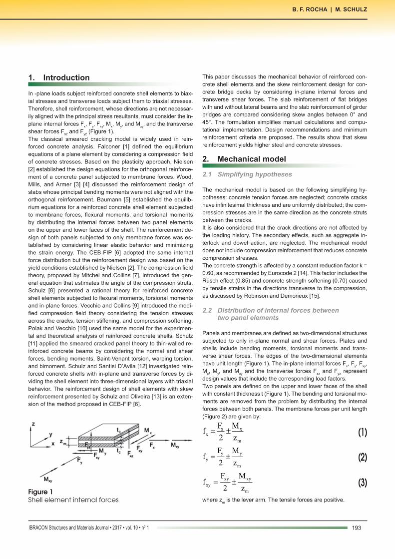
In -plane loads subject reinforced concrete shell elements to biax-ial stresses and transverse loads subject them to triaxial stresses. Therefore, shell reinforcement, whose directions are not necessar-ily aligned with the principal stress resultants, must consider the in-plane internal forces Fx, Fy, Fxy, Mx, My, and Mxy, and the transverse shear forces Fxz and Fyz (Figure 1).The classical smeared cracking model is widely used in rein-forced concrete analysis. Falconer [1] defined the equilibrium equations of a plane element by considering a compression field of concrete stresses. Based on the plasticity approach, Nielsen [2] established the design equations for the orthogonal reinforce-ment of a concrete panel subjected to membrane forces. Wood, Mills, and Armer [3] [4] discussed the reinforcement design of slabs whose principal bending moments were not aligned with the orthogonal reinforcement. Baumann [5] established the equilib-rium equations for a reinforced concrete shell element subjected to membrane forces, flexural moments, and torsional moments by distributing the internal forces between two panel elements on the upper and lower faces of the shell. The reinforcement de-sign of both panels subjected to only membrane forces was es-tablished by considering linear elastic behavior and minimizing the strain energy. The CEB-FIP [6] adopted the same internal force distribution but the reinforcement design was based on the yield conditions established by Nielsen [2]. The compression field theory, proposed by Mitchel and Collins [7], introduced the gen-eral equation that estimates the angle of the compression struts. Schulz [8] presented a rational theory for reinforced concrete shell elements subjected to flexural moments, torsional moments and in-plane forces. Vecchio and Collins [9] introduced the modi-fied compression field theory considering the tension stresses across the cracks, tension stiffening, and compression softening. Polak and Vecchio [10] used the same model for the experimen-tal and theoretical analysis of reinforced concrete shells. Schulz [11] applied the smeared cracked panel theory to thin-walled re-inforced concrete beams by considering the normal and shear forces, bending moments, Saint-Venant torsion, warping torsion, and bimoment. Schulz and Santisi D’Avila [12] investigated rein-forced concrete shells with in-plane and transverse forces by di-viding the shell element into three-dimensional layers with triaxial behavior. The reinforcement design of shell elements with skew reinforcement presented by Schulz and Oliveira [13] is an exten-sion of the method proposed in CEB-FIP [6].
This paper discusses the mechanical behavior of reinforced con-crete shell elements and the skew reinforcement design for con-crete bridge decks by considering in-plane internal forces and transverse shear forces. The slab reinforcement of flat bridges with and without lateral beams and the slab reinforcement of girder bridges are compared considering skew angles between 0° and 45°. The formulation simplifies manual calculations and compu-tational implementation. Design recommendations and minimum reinforcement criteria are proposed. The results show that skew reinforcement yields higher steel and concrete stresses.
2. Mechanical model
2.1 Simplifying hypotheses
The mechanical model is based on the following simplifying hy-potheses: concrete tension forces are neglected; concrete cracks have infinitesimal thickness and are uniformly distributed; the com-pression stresses are in the same direction as the concrete struts between the cracks.It is also considered that the crack directions are not affected by the loading history. The secondary effects, such as aggregate in-terlock and dowel action, are neglected. The mechanical model does not include compression reinforcement that reduces concrete compression stresses.The concrete strength is affected by a constant reduction factor k = 0.60, as recommended by Eurocode 2 [14]. This factor includes the Rüsch effect (0.85) and concrete strength softening (0.70) caused by tensile strains in the directions transverse to the compression, as discussed by Robinson and Demorieux [15].
2.2 Distribution of internal forces between two panel elements
Panels and membranes are defined as two-dimensional structures subjected to only in-plane normal and shear forces. Plates and shells include bending moments, torsional moments and trans-verse shear forces. The edges of the two-dimensional elements have unit length (Figure 1). The in-plane internal forces Fx, Fy, Fxy, Mx, My, and Mxy and the transverse forces Fxz and Fyz represent design values that include the corresponding load factors.Two panels are defined on the upper and lower faces of the shell with constant thickness t (Figure 1). The bending and torsional mo-ments are removed from the problem by distributing the internal forces between both panels. The membrane forces per unit length (Figure 2) are given by:
(1)x xx
m
F Mf
2 z= ±
(2)y y
y
m
F Mf
2 z= ±
(3)xy xy
xy
m
F Mf
2 z= ±
where zm is the lever arm. The tensile forces are positive.Figure 1Shell element internal forces
193IBRACON Structures and Materials Journal • 2017 • vol. 10 • nº 1
B. F. ROCHA | M. SCHULZ
194 IBRACON Structures and Materials Journal • 2017 • vol. 10 • nº 1
Skew decks in reinforced concrete bridges
The panel thickness tc and the lever arm zm are approximately de-fined as:
(4)x y
c c
d dt k
2
+æ ö= ç ÷
è ø
(5)x y
m z
d dz k
2
+æ ö= ç ÷
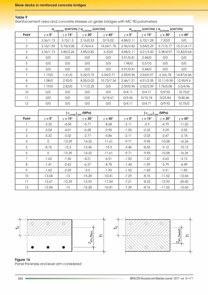
è øwhere dx and dy are the effective depth in the x and y directions, re-spectively. Leonhardt [16] recommends kc = 0.3 and kz = 0.9. The panel thickness tc can be increased on predominantly compressed elements if the lever arm zm is correspondingly reduced (Eurocode 2 [17]).Bertagnoli, Giordano and Mancini [18] proposed a genetic algo-rithm by varying the thickness of the upper and lower plates and lever arms. Schulz [11] divided the shell element into membrane layers whose stresses and strains satisfied equilibrium and com-patibility equations.The principal forces per unit length are:
(6)2
x y x y 2I xy
f f f ff f
2 2
+ -æ ö= + +ç ÷
è ø
(7)2
x y x y 2II xy
f f f ff f
2 2
+ -æ ö= - +ç ÷
è ø
Tension reinforcement is not necessary if both principal forces are negative. In this case, the modulus of the compressive stress must satisfy |fII/tc | ≤ 0.85fc, where fc is defined as the design value of concrete strength.
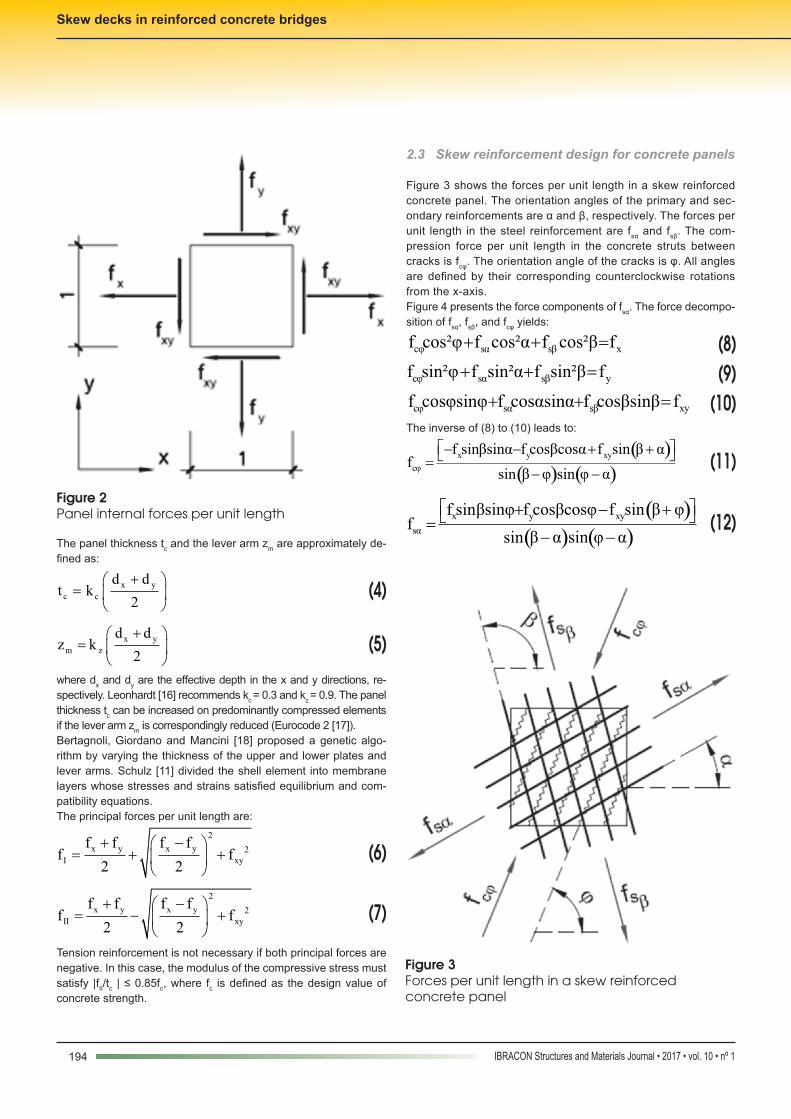
2.3 Skew reinforcement design for concrete panels
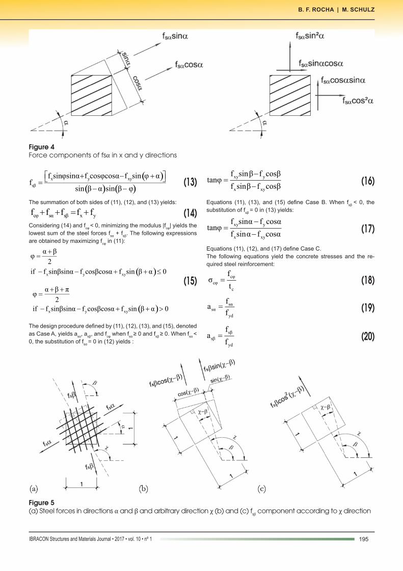
Figure 3 shows the forces per unit length in a skew reinforced concrete panel. The orientation angles of the primary and sec-ondary reinforcements are α and β, respectively. The forces per unit length in the steel reinforcement are fsα and fsβ. The com-pression force per unit length in the concrete struts between cracks is fcφ. The orientation angle of the cracks is φ. All angles are defined by their corresponding counterclockwise rotations from the x-axis.Figure 4 presents the force components of fsα. The force decompo-sition of fsα, fsβ, and fcφ yields:
(8) cφ sα sβ xf cos²φ f cos²α f cos²β f+ + =
(9)cφ sα sβ yf sin²φ f sin²α f sin²β f+ + =
(10) cφ sα sβ xyf cosφsinφ f cosαsinα f cosβsinβ f+ + =
The inverse of (8) to (10) leads to:
(11)( )( ) ( )
x y xy
cφ
f sinβsinα f cosβcosα f sin β αf
sin β φ sin φ α
é ù- - + +ë û=- -
(12)( )
( ) ( )x y xy
sα
f sinβsinφ f cosβcosφ f sin β φf
sin β α sin φ α
é ù+ - +ë û=- -
Figure 2Panel internal forces per unit length
Figure 3Forces per unit length in a skew reinforced concrete panel
195IBRACON Structures and Materials Journal • 2017 • vol. 10 • nº 1
B. F. ROCHA | M. SCHULZ
(13)( )( ) ( )
x y xy
sβ
f sinφsinα f cosφcosα f sin φ αf
sin β α sin β φ
é ù+ - +ë û=- -
The summation of both sides of (11), (12), and (13) yields:
(14) cφ sα sβ x yf f f f f+ + = +
Considering (14) and fcφ < 0, minimizing the modulus |fcφ| yields the lowest sum of the steel forces fsα + fsβ. The following expressions are obtained by maximizing fcφ in (11):
(15)
α βφ
2
+=
( )x y xyif f sinβsinα f cosβcosα f sin β α 0- - + + £
α β πφ
2
+ +=
( )x y xyif f sinβsinα f cosβcosα f sin β α 0- - + + >
The design procedure defined by (11), (12), (13), and (15), denoted as Case A, yields asα, asβ, and fcφ when fsα ≥ 0 and fsβ ≥ 0. When fsα < 0, the substitution of fsα = 0 in (12) yields :
(16)xy y
x xy
f sinβ f cosβtanφ
f sinβ f cosβ
-=
-
Equations (11), (13), and (15) define Case B. When fsβ < 0, the substitution of fsβ = 0 in (13) yields:
(17)xy y
x xy
f sinα f cosαtanφ
f sinα f cosα
-=
-
Equations (11), (12), and (17) define Case C. The following equations yield the concrete stresses and the re-quired steel reinforcement:
(18)
cφ
cφ
c
fσ
t=
(19)sαsα
yd
fa
f=
(20)sβ
sβ
yd
fa
f=
Figure 4Force components of fsα in x and y directions
Figure 5(a) Steel forces in directions α and β and arbitrary direction χ (b) and (c) fsβ component according to χ direction
196 IBRACON Structures and Materials Journal • 2017 • vol. 10 • nº 1
Skew decks in reinforced concrete bridges
where fyd is the design steel strength. The concrete stresses are limited to |σcϕ| < 0.6fcd.
2.4 Minimum reinforcement for skew meshes
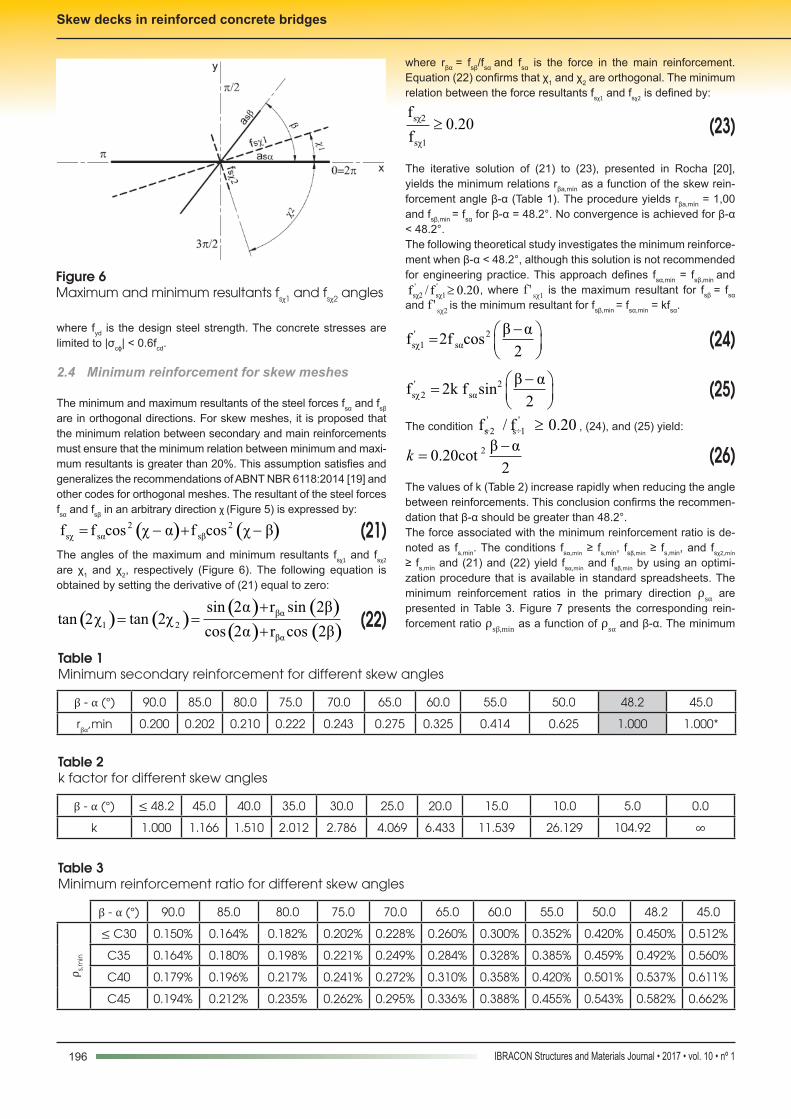
The minimum and maximum resultants of the steel forces fsα and fsβ are in orthogonal directions. For skew meshes, it is proposed that the minimum relation between secondary and main reinforcements must ensure that the minimum relation between minimum and maxi-mum resultants is greater than 20%. This assumption satisfies and generalizes the recommendations of ABNT NBR 6118:2014 [19] and other codes for orthogonal meshes. The resultant of the steel forces fsα and fsβ in an arbitrary direction χ (Figure 5) is expressed by:
(21) ( ) ( )2 2sχ sα sβf f cos χ α f cos χ β= - + -
The angles of the maximum and minimum resultants fsχ1 and fsχ2 are χ1 and χ2, respectively (Figure 6). The following equation is obtained by setting the derivative of (21) equal to zero:
(22)( ) ( )( ) ( )( ) ( )
βα
1 2
βα
sin 2α r sin 2βtan 2χ tan 2χ
cos 2α r cos 2β
+= =
+
where rβα = fsβ/fsα and fsα is the force in the main reinforcement. Equation (22) confirms that χ1 and χ2 are orthogonal. The minimum relation between the force resultants fsχ1 and fsχ2 is defined by:
(23)sχ2
sχ1
f0.20
f³
The iterative solution of (21) to (23), presented in Rocha [20], yields the minimum relations rβa,mín as a function of the skew rein-forcement angle β-α (Table 1). The procedure yields rβa,mín = 1,00 and fsβ,min = fsα for β-α = 48.2°. No convergence is achieved for β-α < 48.2°.The following theoretical study investigates the minimum reinforce-ment when β-α < 48.2°, although this solution is not recommended for engineering practice. This approach defines fsα,min = fsβ,min and
' 'sχ2 sχ1f / f 0.20³ , where f ' sχ1 is the maximum resultant for fsβ = fsα
and f ' sχ2 is the minimum resultant for fsβ,min = fsα,min = kfsα.
(24)' 2sχ1 sα
β αf 2f cos
2
-æ ö= ç ÷
è ø
(25)' 2sχ2 sα
β αf 2k f sin
2
-æ ö= ç ÷
è ø
The condition ' 's÷2 s÷1f / f 0.20≥ , (24), and (25) yield:
(26)2 β α0.20cot
2
-=k
The values of k (Table 2) increase rapidly when reducing the angle between reinforcements. This conclusion confirms the recommen-dation that β-α should be greater than 48.2°.The force associated with the minimum reinforcement ratio is de-noted as fs,min. The conditions fsα,min ≥ fs,min, fsβ,min ≥ fs,min, and fsχ2,mín ≥ fs,mín and (21) and (22) yield fsα,min and fsβ,min by using an optimi-zation procedure that is available in standard spreadsheets. The minimum reinforcement ratios in the primary direction ρsα are presented in Table 3. Figure 7 presents the corresponding rein-forcement ratio ρsβ,min as a function of ρsα and β-α. The minimum
Figure 6Maximum and minimum resultants fsχ1 and fsχ2 angles
Table 1Minimum secondary reinforcement for different skew angles
β - α (°) 90.0 85.0 80.0 75.0 70.0 65.0 60.0 55.0 50.0 48.2 45.0
rβα,min 0.200 0.202 0.210 0.222 0.243 0.275 0.325 0.414 0.625 1.000 1.000*
Table 2k factor for different skew angles
β - α (°) ≤ 48.2 45.0 40.0 35.0 30.0 25.0 20.0 15.0 10.0 5.0 0.0
k 1.000 1.166 1.510 2.012 2.786 4.069 6.433 11.539 26.129 104.92 ∞
Table 3Minimum reinforcement ratio for different skew angles
β - α (°) 90.0 85.0 80.0 75.0 70.0 65.0 60.0 55.0 50.0 48.2 45.0
ρ s,m
in
≤ C30 0.150% 0.164% 0.182% 0.202% 0.228% 0.260% 0.300% 0.352% 0.420% 0.450% 0.512%
C35 0.164% 0.180% 0.198% 0.221% 0.249% 0.284% 0.328% 0.385% 0.459% 0.492% 0.560%
C40 0.179% 0.196% 0.217% 0.241% 0.272% 0.310% 0.358% 0.420% 0.501% 0.537% 0.611%
C45 0.194% 0.212% 0.235% 0.262% 0.295% 0.336% 0.388% 0.455% 0.543% 0.582% 0.662%
197IBRACON Structures and Materials Journal • 2017 • vol. 10 • nº 1
B. F. ROCHA | M. SCHULZ
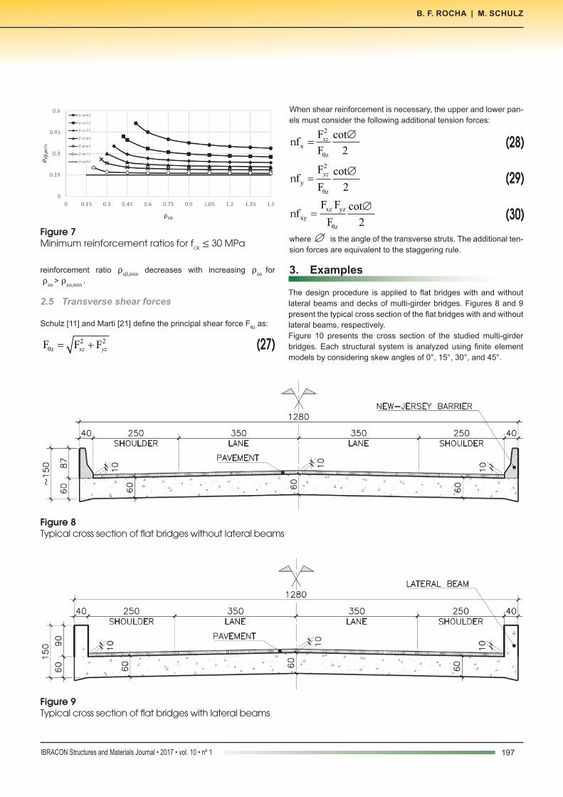
reinforcement ratio ρsβ,min decreases with increasing ρsα for ρsα > ρsα,min .
2.5 Transverse shear forces
Schulz [11] and Marti [21] define the principal shear force Fθz as:
(27) 2 2θzF F F= +xz yz
When shear reinforcement is necessary, the upper and lower pan-els must consider the following additional tension forces:
(28)2
x
θz
F cotf
F 2=n xz Æ
(29)2
y
θz
F cotf
F 2=n yz Æ
(30)xz yz
xy
θz
F F cotf
F 2=n
Æ
where ∅ is the angle of the transverse struts. The additional ten-sion forces are equivalent to the staggering rule.
3. Examples
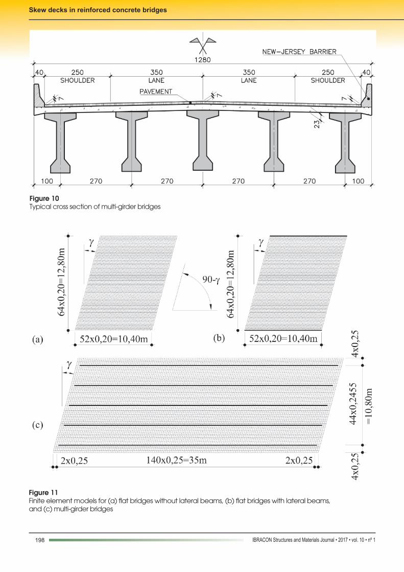
The design procedure is applied to flat bridges with and without lateral beams and decks of multi-girder bridges. Figures 8 and 9 present the typical cross section of the flat bridges with and without lateral beams, respectively. Figure 10 presents the cross section of the studied multi-girder bridges. Each structural system is analyzed using finite element models by considering skew angles of 0°, 15°, 30°, and 45°.
Figure 7Minimum reinforcement ratios for fck ≤ 30 MPa
Figure 8Typical cross section of flat bridges without lateral beams
Figure 9Typical cross section of flat bridges with lateral beams
198 IBRACON Structures and Materials Journal • 2017 • vol. 10 • nº 1
Skew decks in reinforced concrete bridges
Figure 10Typical cross section of multi-girder bridges
Figure 11Finite element models for (a) flat bridges without lateral beams, (b) flat bridges with lateral beams, and (c) multi-girder bridges
199IBRACON Structures and Materials Journal • 2017 • vol. 10 • nº 1
B. F. ROCHA | M. SCHULZ
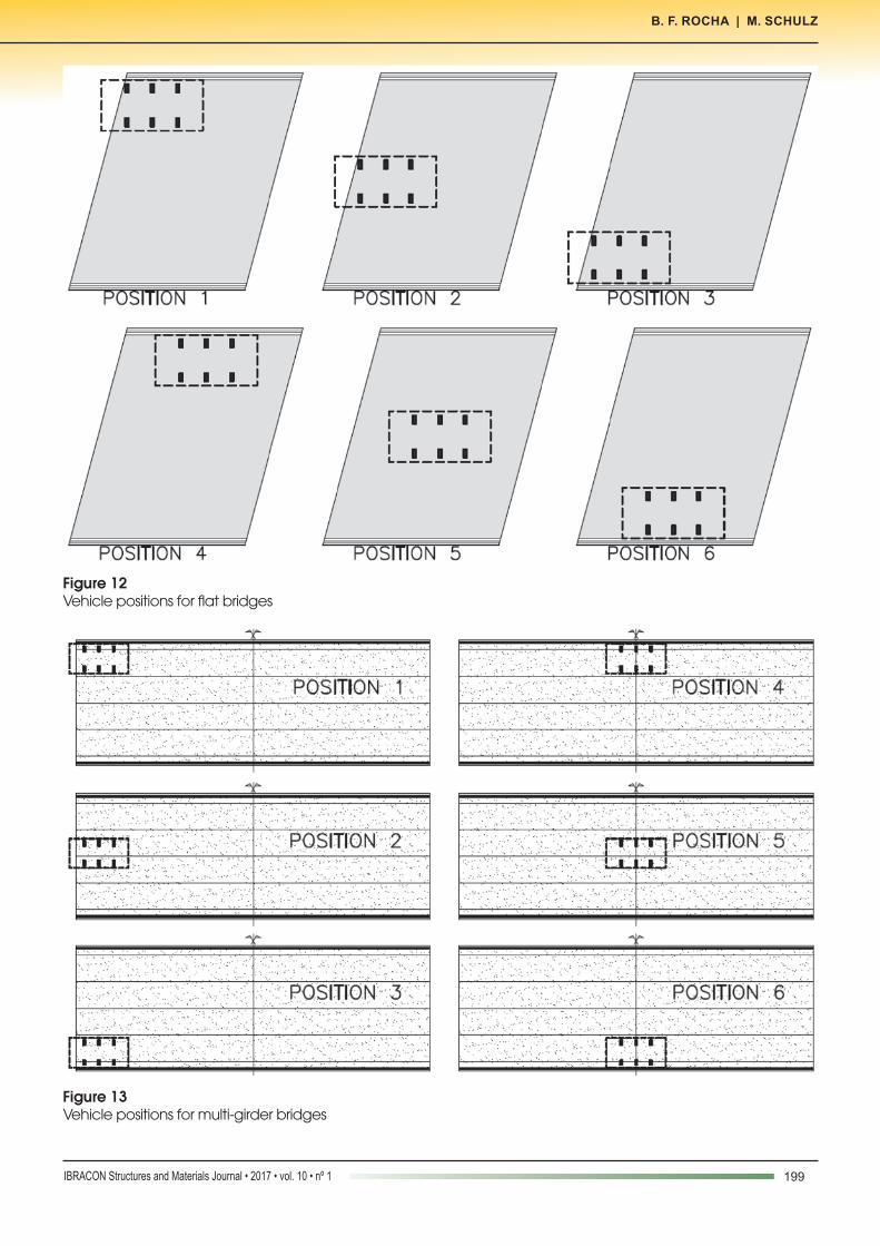
Figure 12Vehicle positions for flat bridges
Figure 13Vehicle positions for multi-girder bridges
200 IBRACON Structures and Materials Journal • 2017 • vol. 10 • nº 1
Skew decks in reinforced concrete bridges
The flat bridges are 0.60 m in height and have a single 10.4 m span in the direction of traffic. The multi-girder bridges have five concrete main girders with a 35m free-span and a 0.23 m thick concrete deck. The width of all bridges is 12.8 m comprising two 3.6 m main lanes, shoulders, and New Jersey barriers. On the flat bridges with lateral beams, the barriers are exchanged for lateral beams 1.5 m in depth (Figure 9).The in-plane reinforcement is determined by the design procedure proposed for skew meshes. The transverse shear reinforcement is verified for the principal transverse shear force. The discussion is limited to the in-plane reinforcement and does not consider service limit states, fatigue, and girders’ prestress.The internal forces are evaluated by linear elastic analysis of fi-nite element models. The mesh patterns of the flat bridge and girder bridge decks are 0.20 m × 0.20 m and 0.25 m × 0.25 m, respectively (Figure 11). Thin-shell elements are used for the slabs and frame elements are used for the beams, and the models are processed on SAP 2000 [22] software. The insertion points of the frame elements are properly defined for the correct evaluation of the in-plane normal forces. The x local axis of the shell elements is defined in the direction of the longitudinal reinforcement and traffic; thus, α is always zero and β is defined as β = 90°-γ, where γ is the skew angle (Figure 11).
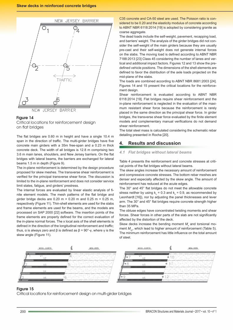
C35 concrete and CA-50 steel are used. The Poisson ratio is con-sidered to be 0.20 and the elasticity modulus of concrete according to ABNT NBR 6118:2014 [19] is adopted by considering granite as coarse aggregate.The dead loads include the self-weight, pavement, recapping load, and barriers’ weight. The analysis of the girder bridges did not con-sider the self-weight of the main girders because they are usually pre-cast and their self-weight does not generate internal forces on the slabs. The moving load is defined according to ABNT NBR 7188:2013 [23] Class 45 considering the number of lanes and ver-tical and additional impact factors. Figures 12 and 13 show the pre-defined vehicle positions. The dimensions of the shell elements are defined to favor the distribution of the axle loads projected on the mid-plane of the slabs.The loads are combined according to ABNT NBR 8681:2003 [24]. Figures 14 and 15 present the critical locations for the reinforce-ment design.Shear reinforcement is evaluated according to ABNT NBR 6118:2014 [19]. Flat bridges require shear reinforcement and the in-plane reinforcement is neglected in the evaluation of the maxi-mum resistant shear force because the reinforcement is rarely placed in the same direction as the principal shear force. In girder bridges, the transverse shear force evaluated by the finite element models and complementary manual verifications do not demand shear reinforcement.The total steel mass is calculated considering the schematic rebar detailing presented in Rocha [20].
4. Results and discussion
4.1 Flat bridges without lateral beams
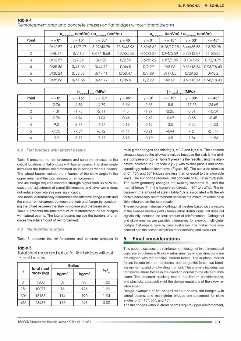
Table 4 presents the reinforcement and concrete stresses at criti-cal points of the flat bridges without lateral beams.The skew angles increase the necessary amount of reinforcement and compressive concrete stresses. The bottom rebar meshes are denser and especially affected by the skew angle. The amount of reinforcement has reduced at the acute edges. The 30° and 45° flat bridges do not meet the allowable concrete stress neither by using kc = 0.3 and kz = 0.9, as recommended by Leonhardt [16]), nor by adjusting the panel thicknesses and lever arm. The 30° and 45° flat bridges require concrete strength higher than 35 MPa.The obtuse edges have concentrated twisting moments and shear forces. Shear forces in other parts of the slab are not significantly affected by the distortion of the deck.Skew decks increase the bending moment Mx and torsional mo-ment Mxy, which lead to higher amount of reinforcement (Table 5). The minimum reinforcement has little influence on the total amount of steel.
Figure 14Critical locations for reinforcement design on flat bridges
Figure 15Critical locations for reinforcement design on multi-girder bridges
201IBRACON Structures and Materials Journal • 2017 • vol. 10 • nº 1
B. F. ROCHA | M. SCHULZ
4.2 Flat bridges with lateral beams
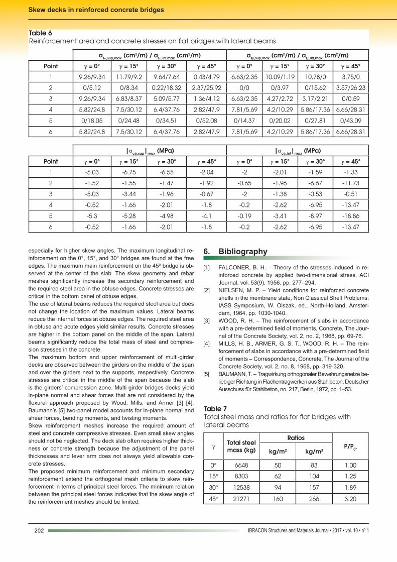
Table 6 presents the reinforcement and concrete stresses at the critical locations of flat bridges with lateral beams. The skew angle increases the bottom reinforcement as in bridges without beams. The lateral beams reduce the influence of the skew angle in the upper mesh and the total amount of reinforcement. The 45° bridge requires concrete strength higher than 35 MPa be-cause the adjustment of panel thicknesses and lever arms does not reduce concrete stresses significantly.The model automatically determines the effective flange width and the shear reinforcement between the web and flange by consider-ing the offset between the slab mid-plane and the beam axis.Table 7 presents the total amount of reinforcement of flat bridges with lateral beams. The lateral beams replace the barriers and re-duces the total amount of reinforcement.
4.3 Multi-girder bridges
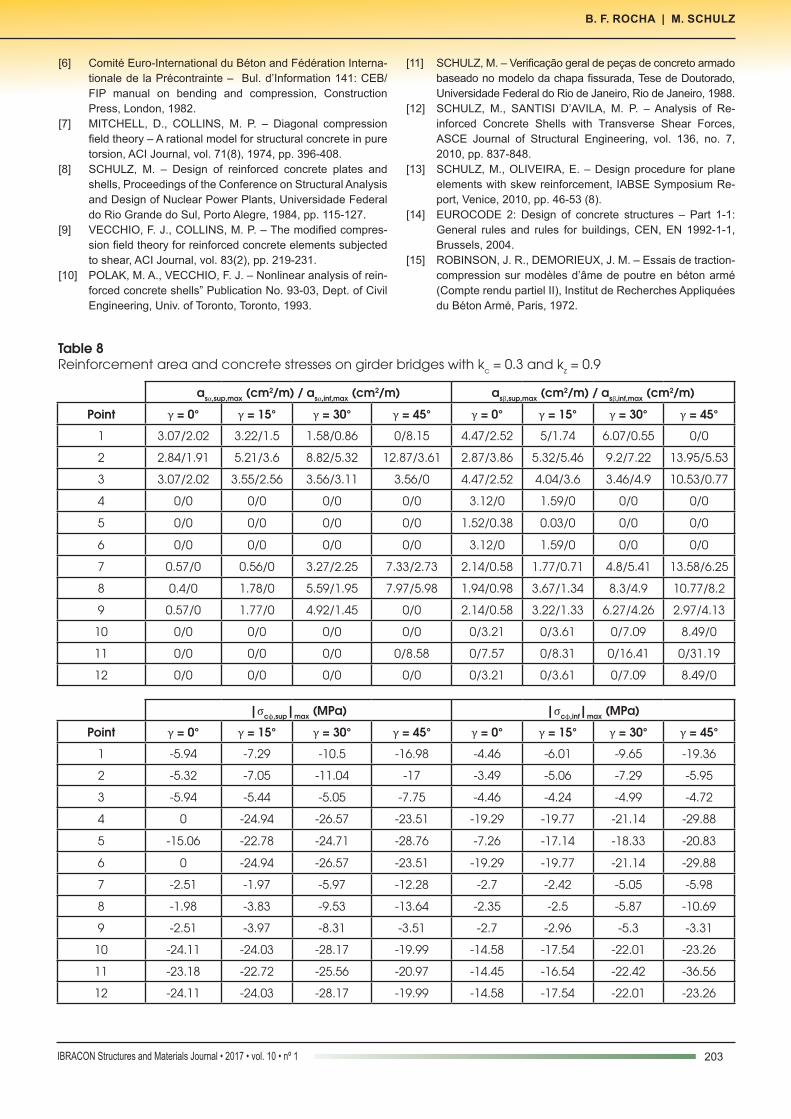
Table 8 presents the reinforcement and concrete stresses in
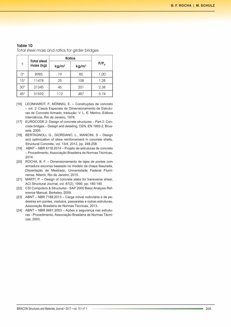
multi-girder bridges considering kc = 0.3 and kz = 0.9. The concrete stresses exceed the allowable values because the slab is the gird-ers’ compression zone. Table 9 presents the results using the alter-native indicated in Eurocode 2 [17], with thicker panels and corre-spondingly reduced lever arms (Figure 16). The concrete stresses of 0°, 15°, and 30° bridges are less than or equal to the allowable limits. The 45º bridge requires C60 concrete or a 0.30 m thick slab.The skew geometry changes the twisting moments Mxy and the normal forces Fy in the transverse direction (90º to traffic). The in-crease in the amount of steel (Table 10) is associated with the ef-fective necessary reinforcement because the minimum ratios have little influence on the total results.The reinforcement design of orthogonal meshes based on the results of the skewed models yield variable rebar distributions that does not significantly increase the total amount of reinforcement. Orthogonal and skew meshes are possible alternatives for skewed multi-girder bridges that require case by case evaluation. The first is more eco-nomical and the second simplifies rebar detailing and execution.
5. Final considerations
This paper discusses the reinforcement design of two-dimensional concrete structures with skew rebar meshes whose directions are not aligned with the principal internal forces. The in-plane internal forces include two normal forces, one tangential force, two bend-ing moments, and one twisting moment. The analysis includes two transverse shear forces in the direction normal to the element mid-plane. The smeared cracking model, equilibrium considerations, and plasticity approach yield the design equations of the skew re-inforcement.Design examples of flat bridges without beams, flat bridges with lateral beams, and multi-girder bridges are presented for skew angles of 0°, 15°, 30°, and 45°.The flat bridges without lateral beams require upper reinforcement,
Table 4Reinforcement area and concrete stresses on flat bridges without lateral beams
asα,sup,max (cm2/m) / asα,inf,max (cm2/m) asβ,sup,max (cm2/m) / asβ,inf,max (cm2/m)
Point γ = 0° γ = 15° γ = 30° γ = 45° γ = 0° γ = 15° γ = 30° γ = 45°
1 0/12.57 4.1/27.27 8.29/40.78 13.5/48.96 3.69/5.62 8.28/17.18 8.44/35.56 2.8/52.98
2 0/8.17 0/9.15 0.67/18.68 4.92/25.88 0.62/3.27 0.94/5.59 5.72/12.97 11.62/23
3 0/12.57 0/7.89 0/4.03 0/2.54 3.69/5.62 0.87/1.85 0.13/1.42 0.12/0.76
4 0/35.86 0/41.56 0/44.77 0/46.8 0/2.29 0/8.05 0.61/13.34 0.98/18.43
5 0/30.24 0/38.33 0/47.41 0/58.47 0/7.89 0/17.05 0/29.63 0/46.2
6 0/35.86 0/41.56 0/44.77 0/46.8 0/2.29 0/8.05 0.61/13.34 0.98/18.43
|σcϕ,sup|max (MPa) |σcϕ,inf|max (MPa)
Point γ = 0° γ = 15° γ = 30° γ = 45° γ = 0° γ = 15° γ = 30° γ = 45°
1 -2.76 -4.39 -4.79 -3.64 -2.68 -8.5 -17.33 -24.69
2 -1.8 -1.75 -2.11 -4.3 -1.27 -2.26 -5.51 -10.54
3 -2.76 -1.94 -1.04 -0.46 -2.68 -0.67 -0.65 -0.45
4 -9.2 -8.77 -7.17 -5.18 -0.19 -3.5 -7.54 -11.53
5 -7.76 -7.34 -6.12 -4.41 -0.21 -4.94 -12 -21.11
6 -9.2 -8.77 -7.17 -5.18 -0.19 -3.5 -7.54 -11.53
Table 5Total steel mass and ratios for flat bridges without lateral beams
γ Total steel mass (kg)
RatiosP/P0°kg/m2 kg/m3
0° 7800 59 98 1.00
15° 10077 76 126 1.29
30° 15153 114 190 1.94
45° 23437 176 293 3.00
202 IBRACON Structures and Materials Journal • 2017 • vol. 10 • nº 1
Skew decks in reinforced concrete bridges
especially for higher skew angles. The maximum longitudinal re-inforcement on the 0°, 15°, and 30° bridges are found at the free edges. The maximum main reinforcement on the 45º bridge is ob-served at the center of the slab. The skew geometry and rebar meshes significantly increase the secondary reinforcement and the required steel area in the obtuse edges. Concrete stresses are critical in the bottom panel of obtuse edges. The use of lateral beams reduces the required steel area but does not change the location of the maximum values. Lateral beams reduce the internal forces at obtuse edges. The required steel area in obtuse and acute edges yield similar results. Concrete stresses are higher in the bottom panel on the middle of the span. Lateral beams significantly reduce the total mass of steel and compres-sion stresses in the concrete.The maximum bottom and upper reinforcement of multi-girder decks are observed between the girders on the middle of the span and over the girders next to the supports, respectively. Concrete stresses are critical in the middle of the span because the slab is the girders’ compression zone. Multi-girder bridges decks yield in-plane normal and shear forces that are not considered by the flexural approach proposed by Wood, Mills, and Armer [3] [4]. Baumann’s [5] two-panel model accounts for in-plane normal and shear forces, bending moments, and twisting moments.Skew reinforcement meshes increase the required amount of steel and concrete compressive stresses. Even small skew angles should not be neglected. The deck slab often requires higher thick-ness or concrete strength because the adjustment of the panel thicknesses and lever arm does not always yield allowable con-crete stresses.The proposed minimum reinforcement and minimum secondary reinforcement extend the orthogonal mesh criteria to skew rein-forcement in terms of principal steel forces. The minimum relation between the principal steel forces indicates that the skew angle of the reinforcement meshes should be limited.
6. Bibliography
[1] FALCONER, B. H. – Theory of the stresses induced in re-inforced concrete by applied two-dimensional stress, ACI Journal, vol. 53(9), 1956, pp. 277–294.
[2] NIELSEN, M. P. – Yield conditions for reinforced concrete shells in the membrane state, Non Classical Shell Problems: IASS Symposium, W. Olszak, ed., North-Holland, Amster-dam, 1964, pp. 1030-1040.
[3] WOOD, R. H. – The reinforcement of slabs in accordance with a pre-determined field of moments, Concrete, The Jour-nal of the Concrete Society, vol. 2, no. 2, 1968, pp. 69-76.
[4] MILLS, H. B., ARMER, G. S. T., WOOD, R. H. – The rein-forcement of slabs in accordance with a pre-determined field of moments – Correspondence, Concrete, The Journal of the Concrete Society, vol. 2, no. 8, 1968, pp. 319-320.
[5] BAUMANN, T. – Tragwirkung orthogonaler Bewehrungsnetze be-liebiger Richtung in Flächentragwerken aus Stahlbeton, Deutscher Ausschuss für Stahlbeton, no. 217, Berlin, 1972, pp. 1–53.
Table 6Reinforcement area and concrete stresses on flat bridges with lateral beams
asα,sup,max (cm2/m) / asα,inf,max (cm2/m) asβ,sup,max (cm2/m) / asβ,inf,max (cm2/m)
Point γ = 0° γ = 15° γ = 30° γ = 45° γ = 0° γ = 15° γ = 30° γ = 45°
1 9.26/9.34 11.79/9.2 9.64/7.64 0.43/4.79 6.63/2.35 10.09/1.19 10.78/0 3.75/0
2 0/5.12 0/8.34 0.22/18.32 2.37/25.92 0/0 0/3.97 0/15.62 3.57/26.23
3 9.26/9.34 6.83/8.37 5.09/5.77 1.36/4.12 6.63/2.35 4.27/2.72 3.17/2.21 0/0.59
4 5.82/24.8 7.5/30.12 6.4/37.76 2.82/47.9 7.81/5.69 4.2/10.29 5.86/17.36 6.66/28.31
5 0/18.05 0/24.48 0/34.51 0/52.08 0/14.37 0/20.02 0/27.81 0/43.09
6 5.82/24.8 7.5/30.12 6.4/37.76 2.82/47.9 7.81/5.69 4.2/10.29 5.86/17.36 6.66/28.31
|σcϕ,sup|max (MPa) |σcϕ,inf|max (MPa)
Point γ = 0° γ = 15° γ = 30° γ = 45° γ = 0° γ = 15° γ = 30° γ = 45°
1 -5.03 -6.75 -6.55 -2.04 -2 -2.01 -1.59 -1.33
2 -1.52 -1.55 -1.47 -1.92 -0.65 -1.96 -6.67 -11.73
3 -5.03 -3.44 -1.96 -0.67 -2 -1.38 -0.53 -0.51
4 -0.52 -1.66 -2.01 -1.8 -0.2 -2.62 -6.95 -13.47
5 -5.3 -5.28 -4.98 -4.1 -0.19 -3.41 -8.97 -18.86
6 -0.52 -1.66 -2.01 -1.8 -0.2 -2.62 -6.95 -13.47
Table 7Total steel mass and ratios for flat bridges with lateral beams
γ Total steel mass (kg)
RatiosP/P0°kg/m2 kg/m3
0° 6648 50 83 1.00
15° 8303 62 104 1.25
30° 12538 94 157 1.89
45° 21271 160 266 3.20
203IBRACON Structures and Materials Journal • 2017 • vol. 10 • nº 1
B. F. ROCHA | M. SCHULZ
Table 8Reinforcement area and concrete stresses on girder bridges with kc = 0.3 and kz = 0.9
asα,sup,max (cm2/m) / asα,inf,max (cm2/m) asβ,sup,max (cm2/m) / asβ,inf,max (cm2/m)
Point γ = 0° γ = 15° γ = 30° γ = 45° γ = 0° γ = 15° γ = 30° γ = 45°
1 3.07/2.02 3.22/1.5 1.58/0.86 0/8.15 4.47/2.52 5/1.74 6.07/0.55 0/0
2 2.84/1.91 5.21/3.6 8.82/5.32 12.87/3.61 2.87/3.86 5.32/5.46 9.2/7.22 13.95/5.53
3 3.07/2.02 3.55/2.56 3.56/3.11 3.56/0 4.47/2.52 4.04/3.6 3.46/4.9 10.53/0.77
4 0/0 0/0 0/0 0/0 3.12/0 1.59/0 0/0 0/0
5 0/0 0/0 0/0 0/0 1.52/0.38 0.03/0 0/0 0/0
6 0/0 0/0 0/0 0/0 3.12/0 1.59/0 0/0 0/0
7 0.57/0 0.56/0 3.27/2.25 7.33/2.73 2.14/0.58 1.77/0.71 4.8/5.41 13.58/6.25
8 0.4/0 1.78/0 5.59/1.95 7.97/5.98 1.94/0.98 3.67/1.34 8.3/4.9 10.77/8.2
9 0.57/0 1.77/0 4.92/1.45 0/0 2.14/0.58 3.22/1.33 6.27/4.26 2.97/4.13
10 0/0 0/0 0/0 0/0 0/3.21 0/3.61 0/7.09 8.49/0
11 0/0 0/0 0/0 0/8.58 0/7.57 0/8.31 0/16.41 0/31.19
12 0/0 0/0 0/0 0/0 0/3.21 0/3.61 0/7.09 8.49/0
|σcϕ,sup|max (MPa) |σcϕ,inf|max (MPa)
Point γ = 0° γ = 15° γ = 30° γ = 45° γ = 0° γ = 15° γ = 30° γ = 45°
1 -5.94 -7.29 -10.5 -16.98 -4.46 -6.01 -9.65 -19.36
2 -5.32 -7.05 -11.04 -17 -3.49 -5.06 -7.29 -5.95
3 -5.94 -5.44 -5.05 -7.75 -4.46 -4.24 -4.99 -4.72
4 0 -24.94 -26.57 -23.51 -19.29 -19.77 -21.14 -29.88
5 -15.06 -22.78 -24.71 -28.76 -7.26 -17.14 -18.33 -20.83
6 0 -24.94 -26.57 -23.51 -19.29 -19.77 -21.14 -29.88
7 -2.51 -1.97 -5.97 -12.28 -2.7 -2.42 -5.05 -5.98
8 -1.98 -3.83 -9.53 -13.64 -2.35 -2.5 -5.87 -10.69
9 -2.51 -3.97 -8.31 -3.51 -2.7 -2.96 -5.3 -3.31
10 -24.11 -24.03 -28.17 -19.99 -14.58 -17.54 -22.01 -23.26
11 -23.18 -22.72 -25.56 -20.97 -14.45 -16.54 -22.42 -36.56
12 -24.11 -24.03 -28.17 -19.99 -14.58 -17.54 -22.01 -23.26
[6] Comité Euro-International du Béton and Fédération Interna-tionale de la Précontrainte – Bul. d’Information 141: CEB/FIP manual on bending and compression, Construction Press, London, 1982.
[7] MITCHELL, D., COLLINS, M. P. – Diagonal compression field theory – A rational model for structural concrete in pure torsion, ACI Journal, vol. 71(8), 1974, pp. 396-408.
[8] SCHULZ, M. – Design of reinforced concrete plates and shells, Proceedings of the Conference on Structural Analysis and Design of Nuclear Power Plants, Universidade Federal do Rio Grande do Sul, Porto Alegre, 1984, pp. 115-127.
[9] VECCHIO, F. J., COLLINS, M. P. – The modified compres-sion field theory for reinforced concrete elements subjected to shear, ACI Journal, vol. 83(2), pp. 219-231.
[10] POLAK, M. A., VECCHIO, F. J. – Nonlinear analysis of rein-forced concrete shells” Publication No. 93-03, Dept. of Civil Engineering, Univ. of Toronto, Toronto, 1993.
[11] SCHULZ, M. – Verificação geral de peças de concreto armado baseado no modelo da chapa fissurada, Tese de Doutorado, Universidade Federal do Rio de Janeiro, Rio de Janeiro, 1988.
[12] SCHULZ, M., SANTISI D’AVILA, M. P. – Analysis of Re-inforced Concrete Shells with Transverse Shear Forces, ASCE Journal of Structural Engineering, vol. 136, no. 7, 2010, pp. 837-848.
[13] SCHULZ, M., OLIVEIRA, E. – Design procedure for plane elements with skew reinforcement, IABSE Symposium Re-port, Venice, 2010, pp. 46-53 (8).
[14] EUROCODE 2: Design of concrete structures – Part 1-1: General rules and rules for buildings, CEN, EN 1992-1-1, Brussels, 2004.
[15] ROBINSON, J. R., DEMORIEUX, J. M. – Essais de traction-compression sur modèles d’âme de poutre en béton armé (Compte rendu partiel II), Institut de Recherches Appliquées du Béton Armé, Paris, 1972.
204 IBRACON Structures and Materials Journal • 2017 • vol. 10 • nº 1
Skew decks in reinforced concrete bridges
Table 9Reinforcement area and concrete stresses on girder bridges with MC 90 parameters
asα,sup,max (cm2/m) / asα,inf,max (cm2/m) asβ,sup,max (cm2/m) / asβ,inf,max (cm2/m)
Point γ = 0° γ = 15° γ = 30° γ = 45° γ = 0° γ = 15° γ = 30° γ = 45°
1 3.36/1.73 3.72/1.3 2.16/0.33 0/15.02 4.88/2.11 5.72/1.28 7.32/0 0/0
2 3.16/1.59 5.74/3.08 9.74/4.4 14.69/1.78 2.96/3.82 5.54/5.29 9.71/6.77 15.31/4.17
3 3.36/1.73 3.85/2.26 3.85/2.82 6.33/0 4.88/2.11 4.21/3.43 3.38/4.97 13.42/0.64
4 0/0 0/0 0/0 0/0 3.91/0.41 2.44/0 0/0 0/0
5 0/0 0/0 0/0 0/0 1.98/0 0.57/0 0/0 0/0
6 0/0 0/0 0/0 0/0 3.91/0.41 2.44/0 0/0 0/0
7 1.19/0 1.61/0 5.32/3.75 6.94/2.71 2.59/0.96 2.53/0.97 6.3/6.78 14.87/6.66
8 1.08/0 2.92/0 8.05/3.02 10.72/7.34 2.46/1.21 4.51/2.05 10.11/5.95 12.95/9.6
9 1.19/0 2.82/0 7.11/2.25 0/0 2.59/0.96 3.92/2.09 7.76/5.08 3.5/4.96
10 0/0 0/0 0/0 0/0 0/4.11 0/4.71 0/9.92 10.75/0
11 0/0 0/0 0/0 0/18.67 0/9.56 0/10.74 0/23.84 0/40.46
12 0/0 0/0 0/0 0/0 0/4.11 0/4.71 0/9.92 10.75/0
|σcϕ,sup|max (MPa) |σcϕ,inf|max (MPa)
Point γ = 0° γ = 15° γ = 30° γ = 45° γ = 0° γ = 15° γ = 30° γ = 45°
1 -3.32 -4.04 -5.77 -8.68 -2.11 -2.9 -4.79 -11.02
2 -3.04 -4.01 -6.28 -9.95 -1.55 -2.32 -3.29 -2.02
3 -3.32 -3.02 -2.77 -5.86 -2.11 -2.03 -2.47 -2.74
4 0 -13.39 -14.32 -11.61 -9.71 -9.95 -10.58 -16.26
5 -8.76 -12.3 -13.46 -15.9 -3.46 -8.55 -9.12 -10.12
6 0 -13.39 -14.32 -11.61 -9.71 -9.95 -10.58 -16.26
7 -1.63 -1.56 -4.21 -6.51 -1.53 -1.47 -3.63 -3.13
8 -1.41 -2.62 -6.37 -8.78 -1.44 -1.59 -3.79 -6.49
9 -1.63 -2.59 -5.5 -1.93 -1.53 -1.65 -3.31 -1.82
10 -13.04 -13 -15.28 -10.41 -7.29 -8.76 -11.52 -12.66
11 -12.67 -12.39 -13.93 -11.54 -7.21 -8.32 -12.93 -25.42
12 -13.04 -13 -15.28 -10.41 -7.29 -8.76 -11.52 -12.66
Figure 16Panel thickness and lever arm considered
205IBRACON Structures and Materials Journal • 2017 • vol. 10 • nº 1
B. F. ROCHA | M. SCHULZ
Table 10Total steel mass and ratios for girder bridges
γ Total steel mass (kg)
RatiosP/P0°kg/m2 kg/m3
0° 8985 19 85 1.00
15° 11478 25 108 1.28
30° 21345 46 201 2.38
45° 51592 112 487 5.74
[16] LEONHARDT, F; MÖNNIG, E. – Construções de concreto – vol. 2: Casos Especiais de Dimensionamento de Estrutu-ras de Concreto Armado, tradução: V. L. E. Merino, Editora Interciência, Rio de Janeiro, 1978.
[17] EUROCODE 2: Design of concrete structures – Part 2: Con-crete bridges – Design and detailing, CEN, EN 1992-2, Brus-sels, 2005.
[18] BERTAGNOLI, G., GIORDANO, L., MANCINI, S – Design and optimization of skew reinforcement in concrete shells, Structural Concrete, vol. 13/4, 2012, pp. 248-258.
[19] ABNT – NBR 6118:2014 – Projeto de estruturas de concreto – Procedimento, Associação Brasileira de Normas Técnicas, 2014.
[20] ROCHA, B. F. – Dimensionamento de lajes de pontes com armadura esconsa baseado no modelo da chapa fissurada, Dissertação de Mestrado, Universidade Federal Flumi-nense, Niterói, Rio de Janeiro, 2015.
[21] MARTI, P. – Design of concrete slabs for transverse shear, ACI Structural Journal, vol. 87(2), 1990, pp. 180-190.
[22] CSI Computers & Structures - SAP 2000 Basic Analysis Ref-erence Manual, Berkeley, 2009.
[23] ABNT – NBR 7188:2013 – Carga móvel rodoviária e de pe-destres em pontes, viadutos, passarelas e outras estruturas, Associação Brasileira de Normas Técnicas, 2013.
[24] ABNT – NBR 8681:2003 – Ações e segurança nas estrutu-ras - Procedimento, Associação Brasileira de Normas Técni-cas, 2003.