Embed Size (px)
DESCRIPTION
SketchList 3D V2 Manual
Citation preview

SketchList 3D User Guide
Software for the Design and Planning of
Cabinetry and Furniture
SketchList 3D Professional
April 2011
www.sketchlist.com

2
SketchList 3D Professional User Guide
Copyright © 2011 SketchList Inc., All Rights Reserved
SketchList Inc.
130 Cabot Street
Milton, MA 02186
USA
http://www.sketchlist.com/

3
Table of Contents
Part 1 Introduction to SketchList 3D
Chapter 1 Introduction to SketchList 3D Professional 6
Chapter 2 Installing and Activating SketchList 3D 11
Chapter 3 SketchList 3D Concepts 17
Chapter 4 Running SketchList 3D for the First Time 25
Chapter 5 Overview of the Main Window 31
Chapter 6 Tutorials 39
Chapter 7 Working with the Areas in the Main Window 73
Chapter 8 Customizing the Views Area 79
Part 2 Designing Projects
Chapter 9 Working with Projects 89
Chapter 10 Working with Assemblies 99
Part 3 Working with Specific Types of Components
Chapter 11 Working with Boards 111
Chapter 12 Working with Joinery 125
Chapter 13 Working with Contours on Boards 139
Chapter 14 Working with Shaped Boards 151


5
Part 1
Introduction to SketchList 3D

6
1
Introduction to
SketchList 3D Professional
SketchList 3D is a software program that allows you to design furniture or cabinetry on your
computer and to automatically prepare parts lists, cutting lists, and shop drawings based on your
design. In SketchList 3D, you work with virtual three-dimensional pieces of wood or another
material, rather than using lines, points, and angles like other design software packages. This
means that you are working with concepts that you already understand, saving you time and
effort in the learning process.
―I am so happy to have this product. It will save me many hours of work and will
break my habit of cutting wood before I have completely planned a project.‖
1.1 How SketchList 3D can help you
SketchList 3D is designed specifically for woodworkers and offers a number of advantages over
traditional CAD software.
SketchList 3D is based on the tasks, methods, and terminology of woodworking, so the
terms and workflow are familiar. For example, to cut a contour on a board edge in
SketchList 3D, you select the edge and pick the contour from a list. SketchList 3D
applies the contour to the board automatically. You add edging, holes, or joinery in the
same way.
It has an intuitive user interface: When you are using SketchList 3D, you work on your
computer screen with virtual pieces of wood or other materials.
It allows you to quickly and easily explore design and materials alternatives.
It automatically produces parts lists, cut lists, purchase lists, and cutting diagrams.
It automates a number of other tasks, as well. For example, it automatically accounts for
grain direction in cutting optimization diagrams and for the effect that a specific joinery
style has on part cut sizes.

7
Its functions are fully integrated. For example, changing the size of a part automatically
modifies the parts list and cutting layout diagram to reflect the part‘s size change.
These benefits allow you to reduce the time spent on design, layout, and planning, which in turn
allows you to increase productivity and save money.
1.2 New features in SketchList 3D Professional
SketchList 3D Professional offers a number of advantages over the earlier version of SketchList
3D. The changes in this version include:
An improved user interface.
Integration of forms.
A powerful spreadsheet editor.
The ability to add joinery on all four edges of a board.
The ability to add contoured edges, holes, and slots.
Photo-realistic 3D renderings.
Improved interface for the shaping of boards.
The ability to slant and rotate boards.
The ability to rotate assemblies in a project.
1.3 Getting help with SketchList 3D
SketchList 3D provides many ways for you to get help, depending on where you are in the
process of learning SketchList 3D and the learning mode you prefer. This section describes the
help resources available to you.
1.3.1 The videos
The SketchList 3D website, www.sketchlist.com, has a number of videos that cover the basics
of learning SketchList 3D:
Entering Customer Information
Adding and Editing Materials
Projects and Assemblies
Locating Objects in 3D
Using the Spreadsheets
Using the Form
Overview of the User Interface
Inserting a Board
Inserting a Door
Inserting a Drawer
Inserting Hardware
Shaping Boards
Adding Contours to Board Edges
Adding Edging to Board Edges

8
Locating and Sizing Holes (Both Round
and Non-round)
Reporting
Creating Photorealistic Images
Exporting to 3D PDF
Using the Optimizer for Material Layouts
Cloning a Single Object
Cloning Multiple Objects
Creating and Using Standard Boards,
Doors, Drawers and Hardware
Creating Hardware
Designing a Door
Designing a Drawer
Importing and Exporting Projects
If you prefer to learn a procedure by watching someone go through the steps, then you may
want to start with the videos.
1.3.2 The tutorials
Chapters 3 to 6 of this manual contains a description of the key SketchList 3D concepts and
several simple tutorials to get you started with the software. The tutorials begin with creating
and locating a board, and move up to building an L-shaped desk. If you‘re primarily a text-
oriented learner, or you like having the steps written down in front of you while you‘re working
so you can refer back to them at any time, then the tutorials are a good place to start.
1.3.3 This manual
This manual provides a description of the features and functions in the SketchList 3D
Professional software. If you are already familiar with the basic SketchList 3D concepts and just
need to find out how to do a certain procedure, then the manual your best bet. Section 1.4
provides a little more information on how to use the manual.
1.3.4 Contacting us
If you have questions about using SketchList 3D, you can write to us at
You can also reach us by regular mail at the following address:
SketchList Inc.
130 Cabot Street
Milton, MA 02186
USA

9
1.4 How to use this manual
This manual contains information about SketchList 3D procedures, forms, and menu
commands. It has a Glossary of terms at the back, and a complete index to help you find the
information you need.
The manual uses a number of conventions to help you understand things a little more quickly.,
as follows:
Left-click means to click the left mouse button, and right-click means to click the right
mouse button.
Control-click means to press and hold down the Control key on your keyboard and, while
still holding it down, click the left mouse button.
Menu commands, button names, and key names are in a special font, like so: Button.
Control, Alt, Shift, and Return are all names for keys on your keyboard.
―Click Track Time‖ means to click the Track Time button in SketchList 3D.
―Choose File > Save Project‖ means to go to the File menu in SketchList 3D and choose
the Save Project command.
SketchList, Inc. is always working to improve its products, so if you have questions about a set
of instructions or a convention in this manual, please write and let us know! It may help save
everyone else a little confusion.
The software you had sent us, was working just fine! We had actually been able
to build not one, but 3 projects on it during our trial period. Our customers have
been really impressed! —Mario


11
2
Installing and Activating SketchList 3D
This chapter covers the computer requirements for running SketchList 3D, how to install
SketchList 3D, and how to activate your SketchList 3D license.
2.1 What do I need to run SketchList 3D?
To run SketchList 3D, you will need:
A computer running Windows XP, Vista, or Windows 7
A copy of the SketchList 3D installation file
Any one of the following:
o A valid SketchList 3D license installed on your computer
o A license key
o An Internet connection to purchase a license key from the SketchList website
2.2 Installing SketchList 3D
To install SketchList 3D:
1. Locate and double-click the SketchList 3D installation file.
A series of screens appears.
2. If the installer tells you it will upgrade an earlier version of SketchList 3D, click OK.

12
The Welcome dialog appears.
3. Click Next.
The End-User License Agreement dialog appears.
4. Check the I accept the terms in the License Agreement checkbox.
5. Click Next.
The Destination Folder dialog appears.

13
6. To use the installation folder that the installer suggests, click Next.
To change the installation folder: Click Change, select a new location in the dialog that
appears and click OK, and then click Next in the Destination Folder dialog.
The Custom Setup dialog appears.
7. Make sure the boxes next to the options you want are checked, and click Next.
If you‘re not sure, leave both boxes checked.
The Ready to Install dialog appears.

14
8. Click Install.
The Installing SketchList 3D Pro dialog appears. The green bars in the Status bar shows
the progress of the installation process.
When the installation has finished, the Completed dialog appears.

15
9. To start using SketchList 3D immediately, check the Launch SketchList 3D Pro when
setup exits box.
10. Click Finish.
2.3 Running SketchList 3D for the first time
The first time you run SketchList 3D, the Reminder dialog appears.
You can run SketchList 3D in trial mode for two weeks, or activate it with a license key. This
section takes you through the steps involved in buying a license key and using it to active
SketchList 3D.
If you already have a license key, skip ahead to Section 2.3.2, Activating SketchList 3D.
2.3.1 Purchasing a license key online
If you do not yet have a license key, you can purchase it online as follows:
1. In the Reminder dialog, click Purchase.
The SketchList 3D website opens in your default browser.
2. In the menu on the left, click Purchase.
3. Follow the instructions on the website.
After you‘ve received your license key, you can activate SketchList 3D by following the
instructions in the next section, Activating SketchList 3D.
2.3.2 Activating SketchList 3D
Once you have a license key, activate your copy of SketchList 3D as follows:
1. In the Reminder dialog, click Activate.
The Enter License Key dialog appears.
16
2. Copy and paste your license key into the Activation key text box.
3. Click Web connection to activate.
At this point, your copy of the SketchList 3D software connects to the SketchList 3D
License Server over the Internet. When your license has been activated, the License
Activated dialog appears.
4. Click Yes to restart SketchList 3D.
The next chapter explains the basic concepts you need to know to work with SketchList 3D.

17
3
SketchList 3D Concepts
Before you run SketchList 3D for the first time, it may be helpful to know a little bit about the
concepts used in SketchList 3D—for example, how projects are broken down into smaller parts
and the different types of components that are available. This chapter provides a basic
introduction to the major concepts used in SketchList 3D.
3.1 The basic objects in SketchList 3D: Projects, assemblies, and components
There are three types (or levels) of objects in SketchList 3D: projects, assemblies, and
components. The following diagram gives a pictorial view of what these objects are and how
they relate to each other. The rest of this section explains these objects and their relationships in
more detail.

18
3.1.1 Projects
The project is the largest object in SketchList 3D and corresponds to the entire piece you are
designing, which could be a full kitchen, a built-in bookcase, a hutch, table, chair, or even a
small box. A project is defined by its name and largest overall dimensions—height, width, and
depth. Each project belongs to a customer.
For more information about what you can do with projects, see Chapter 9, Working with
Projects.
3.1.2 Assemblies
Projects can consist of one or more assemblies, which are coherent pieces of the whole project.
For example, if you‘re designing a desk with a hutch, you could treat the desk and the hutch as
two separate assemblies. An assembly is defined by its name, its overall dimensions, and its
location within the project.
Breaking a project down into assemblies makes it easier to design and copy parts of projects for
use in future designs. For example, you can make a copy of an assembly and use it or modify it
within the same project—if, say, you were designing an office with a number of built-in
bookcases, you could design and place the first bookcase, and then clone that bookcase into
another location in the project and change it if desired.
In some cases, a project may contain only one assembly that corresponds to the whole project;
for example, you probably don‘t need to break a simple bookcase down into two or three
assemblies.
In fact, in general it‘s better to have as few assemblies as you can logically get away with. The
primary reason for this is that a component within an assembly, such as a board, is located in
relation to the leftmost, front-most, and bottom-most corner of the assembly. The components in
one assembly are not directly referenced to components in other assemblies; they are only
indirectly referenced through the project. So when you‘re working with multiple assemblies,
placing a component in one assembly relative to a component in a different assembly sometimes
requires a bit of calculation to get just right.
3.1.3 Components
Assemblies are further broken down into different types of components. A component is
defined by its name, its overall dimensions, and its location within the assembly. SketchList 3D
allows you to include the following types of components in your design:
Boards
Doors
Drawers
Hardware
Boards are the basic components in SketchList 3D. A board is any three-dimensional object
consisting of any material, such as wood, glass, metal, stone, or plastic. Most SketchList 3D

19
users will be working with wood, but SketchList 3D is not restricted to designs in wood. Each
board is assigned a color, grain texture, and transparency, and you can change these properties
to define metal, glass, and even paper components. A board is always created with four edges
and two surfaces. For more information about boards, see Chapters 10 to 13.
Doors and drawers are categories that consist of other components. A door or drawer contains
any number of boards and may also contain hardware.
Hardware includes objects such as hinges, handles, and drawer slides. You can design any three
dimensional object in SketchList 3D, so you can create your own hardware objects, or use the
hardware objects included with SketchList 3D.
A project with all levels of components would have a hierarchy like the following:
Such a project might look something like the diagram in Figure 3.1:

20
Figure 3.1 A project with all levels of components
This project is rendered in 3D as in Figure 3.2. Notice that the gray-ish boundary boxes around
the components in Figure 3.1—assemblies, doors, and drawers—are not shown in the finished
3D rendering in Figure 3.2.
Figure 3.2 A 3D rendering of a project with all levels of components

21
3.2 Positioning components within an assembly, and assemblies within a project
The position of a component within an assembly is determined by the relationship between the
component‘s bottom left front corner and the assembly‘s bottom left front corner. To position a
component, you specify where its bottom left front corner is located with respect to the
assembly.
As an example, let‘s take a cabinet that is 36 inches wide and has two doors that are each 17
inches wide and ¾ inch thick (deep). Both doors are ½ inch from the edges of the cabinet and
flush with its front. There is a one-inch gap between the doors.
The Front value of the cabinet frame or carcass is ¾ to allow for the ¾-inch thickness of the
doors. The Front values of the doors are both zero, putting them flush with the front of the
defined area of the assembly. The doors have a back value of ¾ (zero front plus ¾-inch depth),
putting the backs of the doors flush with the front of the cabinet frame.
Note: When you size a project and assembly, remember to allow space on the
front for doors, drawer fronts, and even face frames. Setting the front of the
carcass to 0 and then placing doors with a front value of 0 will require you to add
the thickness of the doors to the front values of all carcass members in order to
move the carcass members towards the back.

22
The left door will have a Left value of ½. That is, the left edge of the left door is ½ inch from
the left edge of the cabinet. The right edge of the left door is 17 ½. that is 17 inches for the door
width plus the ½ inch that the door is from the left of the cabinet. The left edge of the right door
is 18 ½ inches, which is 1 inch from the right edge of he left door (17 ½‖). The right edge of the
right door is 35 ½ inches which is the left edge of 18 ½ inches plus the 17 inch width of the
right door.
You position an assembly within a project in the same way.
When you reposition an assembly within a project, the relationship between the assembly and
the project changes, but the relationship between the assembly and its components does not
change. In other words, the components move together with the assembly and retain their
original relationships with the assembly.
Note: You don‘t have to think of all locations within a project as originating from
the lowest, left-most, bottom-most corner of the project. For example, if you have
a board with a right edge of 3 inches, and you want to add another board with a
left edge that is spaced 3 inches from the original board, you would enter 6 for the
left edge of the second board. But you could think of that point as either 6 inches
from the left of the project or as 3 inches from the original board.

23
3.3 Views
In addition to a three-dimensional perspective view, each object has six views in three-
dimensional space:
Front Left Top
Back Right Bottom
In SketchList 3D you are always designing relative to the front, left, and bottom of the
project/assembly. You may of course see your design from any of the six views one at a time,
or by spinning the perspective view by dragging it with your cursor.
3.4 Dimensions and measurements
Whenever you create a project in SketchList 3D, you‘re asked to specify the overall dimensions
of the project and whether these dimensions are imperial or metric. If you choose imperial, then
you should enter all your dimensions in inches; if you choose metric, then you should use
centimeters throughout the project. You can select different units for different projects.
When you enter the dimensions for a project, assembly, or component, you only have to enter
the numbers; there is no need to enter the units. SketchList 3D remembers the units you chose at
the start of the project and applies them throughout the project.


25
4
Running SketchList 3D for the First
Time
The first time you run SketchList 3D, you‘ll be prompted to
Enter information about you and your shop (optional)
Enter information about a customer
Create a project for that customer
This chapter takes you through each of these steps.
4.1 Entering information about you and your shop
When you run SketchList 3D for the first time, the Application Set-Up Wizard opens, asking
you to enter information about yourself and your shop. This section explains how to fill in the
Application Set-Up Wizard.

26
1. Uncheck the Show at startup button.
You can change any of the information in this wizard from within SketchList 3D, so you
don‘t need to see the wizard every time you start SketchList 3D.
2. Click Next>.
The next screen in the Application Set-Up Wizard appears.

27
3. Fill in information about yourself and your company.
You can enter as much or as little information as you‘d like. This information is used for
report headings, if you choose to include your company‘s identification information on
your reports.
4. Click Next> to move to the final screen of the Application Set-Up Wizard.
5. Click Finish to exit the Application Set-Up Wizard.
The Project Set-Up Wizard appears. This Wizard is described in the next sections,
Entering information about a customer and Creating a project.

28
4.2 Entering information about a customer
Before you can start building projects in SketchList 3D, you need to set up at least one
customer. If you want to experiment, you can set yourself up as the customer, or set up a test
customer such as John Doe. You can always edit or delete these experimental customers later.
To set up a customer:
1. In the Project Set-Up Wizard, click Create New Customer.
The customer-related fields, such as Name and Address, turn white, indicating that you
can fill them in.
Click here.

29
2. Fill in the customer‘s name and any other information you would like to store in
SketchList 3D.
You can leave everything blank except the Name box.
3. Click Save Customer.
4.3 Creating a project
Once you have set up a customer, you can create a project associated with that customer. To do
this:
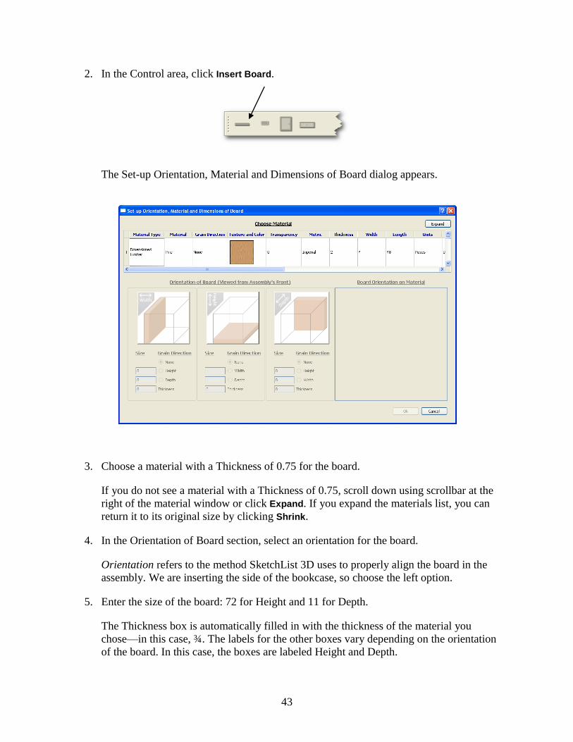
1. In the Project Set-Up Wizard, click Create New Project.
Click here.
The Project Information dialog appears.

30
2. In the Project Name box, enter a name for the project.
If you are planning to work through the first tutorial in Chapter 6, building a bookcase,
type ―Bookcase‖ in the Project Name box.
3. In the Dimensions pane, enter the total height, width, and depth for the project in the
appropriate box.
As an example, if you‘re designing an L-shaped desk with a hutch on top of one side, the
height of the project would be the total height of the desk plus the total height of the
hutch. If the two lengths of the L are 60 inches and 30 inches, the total width and depth of
the project would be 60 by 30.
For now, put 72, 24, and 11, respectively. These are the dimensions of the bookcase that
you will build if you work through the tutorials in Chapter 6.
4. Click OK.
5. To start designing your project, select it in the Project Set-Up Wizard and click Load
selected project.
To help you get started more quickly, these instructions skipped some parts of the
Project Information dialog. If you have questions about the parts that were skipped, see
Section 9.2, Creating a new project.
The next chapter provides an introduction to the areas in the SketchList 3D main window. The
bookcase tutorial continues in Chapter 6, along with additional tutorials that build more
complex projects.

31
5
Overview of the Main Window
This chapter provides a brief overview of the SketchList 3D main window and its different
areas. For more detailed instructions on how to work with each of the areas, see Chapter 7.
5.1 The main window
After you start SketchList 3D and create or select a project to work on, the main SketchList 3D
window appears. The main window contains five areas: the Views area, the Control area, the
Form area, the Spreadsheet area, and the Hierarchical Levels area.
Views area Control area Form area
Spreadsheet area Hierarchical Levels area

32
The rest of this chapter describes these areas and how to work with them.
5.2 The Control area
The Control area contains the SketchList 3D menu bar and some helpful icon and button
shortcuts. You can use the buttons under the icon bar to render your project, export your project
to PDF, and start or stop tracking time. The Control area also shows the time spent on the
project so far.
The Control area also shows the names of the currently selected project and assembly, as well as
their sizes, because it is often useful to know the overall size of the level you‘re working with.
For more information on using the menu commands and icons in the Control area, see Section
7.1, The menu bar and right-click menus, and Section 7.2, The icon bar, respectively.
5.3 The Views area
By default, the Views area starts off with four views of a project or assembly, which are labeled
Top, Front, Right, and Perspective. You can change the number of views, and can also see
Back, Bottom, and Left views of the current project or assembly.
The next two sections describe the seven views in greater detail.
5.3.1 The Top, Bottom, Front, Back, Left, and Right Views
Each of the Top, Bottom, Front, Back, Left, and Right views displays the specified view of the
current object in 2D. For example, the Right view displays the right view of the current project,
assembly, or component. Other labels at the edges of the view, such as Front and Back or Top
and Bottom, help you keep track of the object‘s orientation.

33
Figure 5.1 Right view of a bookcase
The outline of the object—project or assembly, depending on the level you are looking at—is
shown as a shadowed container that encloses all the components belonging to the object. Below
and outside of the object, there is an image of a floor to help anchor the design.
Each of these views has a background grid by default. When you position your cursor over the
grid, a pop-up window shows the distance from that point to two of the left, back, and bottom
edges of the object, depending on the view.
For more information on viewing the different sides of an object, see Chapter 8.
5.3.2 The Perspective view
The Perspective view provides a 3D view of a project or assembly. Unlike the other views, the
Perspective view does not have a background grid, and the cursor location is not displayed.

34
Figure 5.2 Perspective view of a bookcase
For instructions on how to manipulate the object in the Perspective view, see Chapter 8.
5.4 The Spreadsheet area
The main Spreadsheet area is located directly underneath the Views area and provides
information about the objects in the current level, their locations, and their dimensions. You can
edit this information in the Spreadsheet or in the Form area (see Section 5.5).
Figure 5.3 Assembly Spreadsheet for a bookcase
The types of objects shown in the spreadsheet depend on the level of spreadsheet that you are
viewing. There are several types of spreadsheets, as follows:

35
The Project spreadsheet contains information about the assemblies within the current
project.
The Assemblies spreadsheet contains information about all the components in the
currently-selected assembly.
The Drawer, Door, and Hardware spreadsheets contain information about drawers, doors,
and hardware, respectively.
The General spreadsheet contains a list of all the objects in the current project and their
locations and dimensions. The objects are grouped by assembly. By default, this
spreadsheet does not appear in the main window, but you can open it with the
View > Spreadsheet > General Spreadsheet command.
At any level, you can also open a spreadsheet for each type of component in an
assembly—for example, all the drawers in the assembly. To do this, select an assembly
and choose View > Spreadsheets > Assembly’s Content.
You can use the Spreadsheet area to keep notes about some or all of the objects in the list. For
example, if you‘re building a bookcase, as in the tutorial in Section 6.1, you could add a note
that the space between the top of the bookcase and the topmost shelf is 10 inches high. Any
notes you type into the Spreadsheet notes cell also appear in the appropriate object form in the
Form area.
5.5 The Form area
The Form area contains information about the currently selected assembly or component.

36
Figure 5.4 Form area showing an Assembly form
To look at the information in an object‘s Form, select the object in the Views area or the
Spreadsheet area. The amount of information shown in the form varies depending on what type
of object is selected. You can use the form to change the object‘s name, location, and
dimensions; add notes about the object; clone or delete the object, and much more.
5.6 The Hierarchical Levels area
The Hierarchical Levels area allows you to move from one object level to another. For example,
you can move from the project level to the assembly level by selecting Assembly Level within
this area.
Figure 5.5 Hierarchical Levels area

37
The three possible levels in the Hierarchical Levels window are:
The Project Level—allows you to work with assemblies in the Views, Spreadsheet, and
Form areas.
The Assembly Level—allows you to work with components in the different areas.
The Component Level—allows you to work with different aspects of the currently-
selected component. For example, if a board is selected, you can work with the board‘s
edges and surfaces. Each component has its own level; for example, you work with
boards at the Board Detail Level, and with drawers at the Drawer Level.


39
6
Tutorials
This chapter takes you through several tutorials, starting with designing a simple bookcase and
moving on to a more complicated project—a desk with a drawer and hutch. These tutorials
include sections on working with boards and on moving your project from the computer to the
real world.
If you worked through the steps in Chapter 4, Running SketchList for the First Time, you now
have the beginnings of a project open in SketchList 3D—either a bookcase or your own project.
The next sections assume that you have already set up a project and are ready to start the design
process.
6.1 Building a bookcase
This section explains how to build a bookcase, including the steps to create an assembly within
your new project and to locate a board within the assembly. The instructions assume that you‘re
building a bookcase, but if you‘re working on your own project, you can adapt the instructions
as necessary.
6.1.1 Creating an assembly
Boards are positioned in relation to assemblies, so before you can start placing boards in a
project, you first need to create an assembly. For more information on the relations between the
different elements, see Section 3.1.
To create an assembly:
1. Click the Insert Assembly button in the Control area.
The Assembly Form becomes active.
2. In the Assembly Form, type a name for the assembly, such as Bookcase Assembly.

40
Each assembly in a project must have a unique name. It‘s best to name your assemblies in
the way that‘s easiest for you to remember. For example, if you‘re building a desk with a
hutch, you might want to name one assembly Desk and the other Hutch.
After you‘ve named an assembly, the next step is to enter its dimensions. A
straightforward bookcase is best designed with one assembly, so you can enter the same
dimensions for the assembly that you entered for the project in Section 4.3: 72 x 24 x 11.
3. In the Dimensions pane, enter 72 for Height, 24 for Width, and 11 for Depth.
Initially, the other numbers in the Location pane become red. This indicates that the
numbers don‘t add up. As an example in this case, the number in the Bottom box, which
is currently set to 0, plus the number in the Height box—currently 72—does not equal the
number in the Top box, which is currently 0. In short, the current settings are 0 + 72 = 0,
which is not correct.

41
In this case, the bottom, left, and front edges of the assembly are the same as those of the
project, so leave these numbers at 0.
However, the numbers in the Top, Right, and Back boxes should be equal to the bottom,
left, and front edges plus the assembly‘s height, width, and depth, respectively. That is,
the Top edge is calculated according to the following formula:
Bottom + Height = Top 0 + 72 = 72
In other words, the number in the Top box should be equal to 72, or in other words, 0 (the
number in the Bottom box) plus 72 (the Height). The following table provides the
formulas for calculating each of the edges and dimensions.
Front = Back - Depth
Depth = Back - Front
Back = Front + Depth
Bottom = Top - Height
Height = Top - Bottom
Top = Bottom + Height
Left = Right - Width
Width = Right - Left
Right = Left + Width
4. In the Top box, enter 72 and press the Tab key.
The number in the Top box changes to green, indicating that the numbers in the Bottom,
Height, and Top boxes are all coordinated.

42
5. Click the Right and Back buttons.
The numbers in these boxes change to 24 and 11, respectively. Clicking the buttons
means you don‘t have to type in the numbers manually, as you did in step 4; SketchList
3D fills in the boxes for you automatically.
You‘ve now entered enough information about this assembly to continue with the tutorial.
6.1.2 Creating, sizing, and placing a board in an assembly: Adding the left side board to the bookcase
Now that you have an assembly, you can insert your first board. To do this:
1. In the Hierarchical Levels area, click Assembly Level.
This switches the object in the Views area from a project to an assembly and allows you
to work with the components in the assembly.
Click here.
43
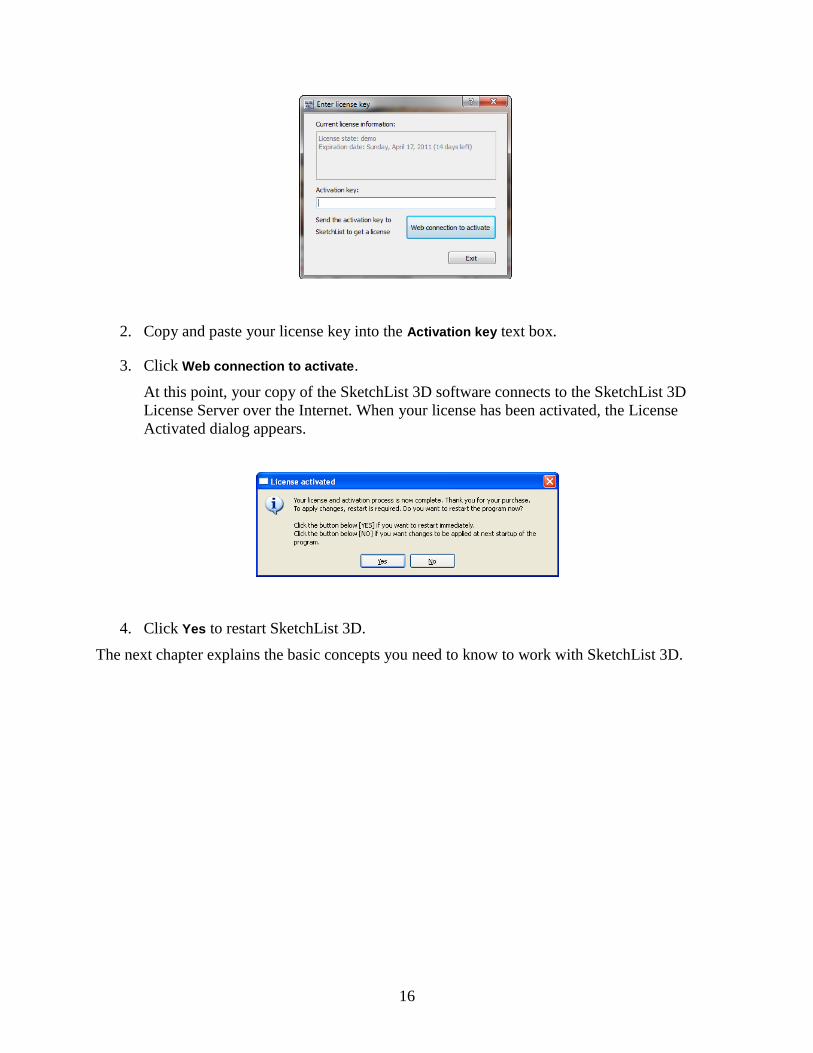
2. In the Control area, click Insert Board.
The Set-up Orientation, Material and Dimensions of Board dialog appears.
3. Choose a material with a Thickness of 0.75 for the board.
If you do not see a material with a Thickness of 0.75, scroll down using scrollbar at the
right of the material window or click Expand. If you expand the materials list, you can
return it to its original size by clicking Shrink.
4. In the Orientation of Board section, select an orientation for the board.
Orientation refers to the method SketchList 3D uses to properly align the board in the
assembly. We are inserting the side of the bookcase, so choose the left option.
5. Enter the size of the board: 72 for Height and 11 for Depth.
The Thickness box is automatically filled in with the thickness of the material you
chose—in this case, ¾. The labels for the other boxes vary depending on the orientation
of the board. In this case, the boxes are labeled Height and Depth.

44
6. Set the grain direction of the board.
Under Grain Direction, choose None (if grain direction does not matter) or assign the
grain direction to either the Height or the Width. The grain direction on the material
dictates the layout of the optimized material layout diagrams, so setting the grain
direction is important for aligning the board onto the material.
7. Use the Board Direction on Material area to verify the direction of the board on the
material and make sure you have the correct material before you proceed.
8. Click OK.
The board appears in the Views area, and the Form and Spreadsheet area change. The
Form area now contains a Board Form, and the Spreadsheet area contains information
about the new board‘s name, location, and dimensions.
9. In the Form area, double-click in the Unique Name textbox and enter Left Side Board.
SketchList 3D automatically creates names for objects, but when you are working on a
very complex project or assembly, these automatically-created names may not be
informative enough to identify the objects. It‘s therefore better to name each object when
you create it, including cloned objects. Choose a name that is easy to remember, like
―Left Side Board‖ for this board, or ―Middle Shelf Divider‖ for a board in a more
complicated project. After you type in the name, the Spreadsheet area automatically
changes to reflect the new name.
The next section steps you through the procedure for adding the bottom of the bookcase.
6.1.3 Adding the bottom board to the bookcase
To add the bottom board to the bookcase:
1. Click Insert Board.
2. In the dialog that appears, choose a material for the board.

45
3. For the board‘s orientation, choose the middle box.
4. Enter 22.5 for the board‘s width and 11 for its depth.
The board should be 22.5 inches wide rather than 24 because it will be inset between the
Left Side Right Side Boards, which are both ¾ inch thick, and therefore ¾ inch in width
(1.5 inches for both boards).
5. Set the grain direction to Width.
6. Click OK.
7. In the Spreadsheet area, under the Views area, locate the new board, which is named
Board1.
8. Double-click the new board‘s name and type in Bottom Board.
In future, you can change an object‘s name in either the Form area or the Spreadsheet.
The Bottom Board is currently aligned with the left side of the assembly. However, the
Left Side Board is also aligned with left side of the assembly, so at the moment, the two
boards are occupying some of the same space. The next step is to move the Bottom Board
¾ inch to the right—the thickness of the Left Side Board—so that the Bottom Board buts
against the Left Side Board‘s right side. Use the Spreadsheet area to position the board.
(We‘ll use the Board Form to do this in a later step.)
9. Press Tab to move from the current cell (the board‘s name) to the next cell, which is in
the Left column.
10. Enter 0.75 for the Left value.
11. Press Tab twice to move to the Right column.
12. Enter 23.5 for the Right value.
The Bottom Board should now have a Left value of ¾, a Width of 22.5, and a Right value
of 23.25. In the Perspective view, there is a small blank space to the right of the Bottom
board where the Right Side Board will go.
The next section takes you through adding the top board.
6.1.4 Adding the top of the bookcase
To add the top of the bookcase:
1. Click Insert Board.
2. In the dialog that appears, choose a material for the board.
3. For the board‘s orientation, choose the middle box.

46
4. Enter 22.5 for the board‘s width and 11 for its depth.
The Top Board will be inset between the Left Side and Right Side Boards, which are both
¾ inch thick, and therefore ¾ inch in width.
5. Choose a grain direction.
6. Click OK.
7. In the Board form, rename the board to Top Board.
So far, these steps have been pretty much identical to the steps in creating the bottom
board, and in fact, the two boards are currently occupying the same space. The next steps
reposition the Top Board at the top of the bookcase and inset it between the Left Side and
Right Side Boards. This time, use the Board form.
8. In the Location pane, enter 71 ¼ in the Bottom box.
9. Press Tab four times to move to the Top box.
10. Enter 72 in the Top box.
These steps tell SketchList 3D that you want the bottom of the board to be located near
the top of the assembly. The assembly is 72 inches high, and the board is ¾ inch thick
(or, in this case, ¾ inch high), so the bottom of the board is at 71.25 (Height – Thickness
= Bottom, or 72 – 0.75 = 71.25).
Next, we need to move the top board to the right by ¾ inch, as we did for the bottom
board.
11. Press Tab twice to move to the Left box.
12. Enter ¾ in the Left box.
13. Click Right.
SketchList 3D automatically adjusts the Right value based on the values for Left and
Width. The Bottom Board now has a Left value of ¾, a width of 22 ½, and a Right value

47
of 23 ¼, and it now appears in the Views area at the top of the assembly. You can check
this in the Spreadsheet area:
In the next section, you‘ll add the back of the bookcase.
6.1.5 Adding the back of the bookcase
To add the back of the bookcase:
1. Click Insert Board.
2. In the dialog that appears, choose a material with a Thickness of ¼.
3. For the board‘s orientation, choose the box on the right.
4. Enter 72 for the board‘s height and 24 for its width.
This gives the bookcase a full back.
5. Choose a grain direction.
6. Click OK.
7. In the Board area, rename the board to Back.
At this point, there is a slight problem: this board is currently in the front of the assembly,
not the back. The next two steps show you how to check the board‘s location using the
Perspective view.
8. In the Views area, locate the Perspective pane.
9. Position your left mouse button over the assembly in the Perspective pane, click and hold
it, and move your mouse to the left.
The assembly starts to rotate. The board you just created is the board closest to you, or
the front of the bookcase. You can repeat this step if you want to look at the bookcase
from all angles or want to return it to its original view. In the next step, you‘ll move the
board to the back of the assembly.
10. In the Location pane of the Board area, enter 11 for the Back.

48
In the Views area, the board appears at the back of the assembly. You can check this in
the Top view of the assembly; the green board is at the top of the view, which is labeled
Back (since this view presents the assembly from the top, as if you were looking down on
it).
You may be able to see that, at this point, the Left, Bottom, and Top Boards collide with
the Back board. The Back board is ¼ inch thick and has a back value of 11, giving it a
front value of 10 ¾. The next step is to change the back values of the other three boards
from 11 to 10 ¾ to butt them against the Back board.
11. In the Spreadsheet area, change the Depth and Back values for the Left, Bottom, and Top
Boards to 10 ¾.
Next, add the right side of the bookcase.
6.1.6 Adding the right side of the bookcase
There are two options for adding the right side of the bookcase. You can either create a new
board, as described in previous sections, or clone the Left Side Board and move the cloned
board to the right side of the assembly. This section describes how to clone the Left Side Board.
If you choose to create a new board, give it the following location and dimensions in the
Spreadsheet or Board form:
Bottom: 0 Height: 72 Top: 72
Left: 23.25 Width: .75 Right: 24
Front: 0 Depth: 10.75 Back: 10.75
To clone the Left Side board:
1. In the Spreadsheet area, right-click anywhere in the Left Side Board row and choose
Clone.
A new row named Left Side Board(clone1) appears in the spreadsheet, with exactly the
same values as the original Left Side Board. The new board isn‘t visible in the Views
area because it is occupying the same position as the Left Side Board. In the next steps,
we‘ll rename the new board and move it over to the right edge of the assembly.

49
2. Double-click the new board‘s name and rename it to Right Side Board.
3. Press Tab to move to the Left column in the Spreadsheet.
4. Change the left value to 23.25.
5. Click in the heading area of the Right column.
SketchList 3D automatically changes the Right value for you.
The new Right Side board is now visible on the right of the assembly. The top, bottom,
and back values for the Right Side have been copied from the Left Side board, so the
Right Side butts up neatly against the other boards.
Next, add the first shelf.
6.1.7 Adding a shelf
Before creating a new board in SketchList 3D, take a moment to decide where you want the first
shelf in the bookcase to be located. Let‘s say you want a 10-inch space between the top of the
bookcase and the first shelf. In the bookcase shell you‘ve built, the bottom edge of the top board
is located at 71 ¼ inches, so to get the full 10 inch space, you want the top edge of the shelf to

50
be located at 61 ¼ inches. Since the shelf is ¾ inch thick, the bottom edge of the shelf will be at
60 ½ inches.
Top Board‘s top edge – Thickness = Top Board‘s bottom edge 72 – ¾ = 71 ¼
Top Board‘s bottom edge – book space = Shelf‘s top edge 71 ¼ – 10 = 61 ¼
Shelf‘s top edge – Thickness = Shelf‘s bottom edge 61 ¼ – ¾ = 60 ½
To add a shelf, you can either create a new board or clone the existing Bottom Board and move
it to the correct position. If you create a new board, give it the following location and
dimensions:
Bottom: 60.5 Height: .75 Top: 61.25
Left: .75 Width: 22.5 Right: 23.25
Front: 0 Depth: 10.75 Back: 10.75
To clone the Bottom Board and move it:
1. In the Perspective view, select the Bottom Board.
This is a different way of cloning the board than described in Section 6.1.6, Adding the
right side of the bookcase. The Bottom Board will turn green to indicate that it is
selected.
2. Right-click and choose Clone selected.
A new row named Bottom Board(clone1) appears in the spreadsheet, with exactly the
same values as the original Bottom Board. The new board isn‘t visible in the Views area
because it is occupying the same position as the Bottom Board. SketchList 3D adds a
yellow highlight to cloned objects in the spreadsheet to indicate that you need to change
their location values. In the next steps, you‘ll rename the new board and move it up to the
correct location.
3. Using either the Spreadsheet or the Board form, rename the new board to Shelf Board.
4. Press Tab to move to the Left column in the Spreadsheet.
5. Change the Bottom value from 0 to 60.5.
6. If you are using the Spreadsheet, click the Top heading. If you are using the Board form,
click the Top button.
SketchList 3D automatically changes the Right value for you.

51
At this point, you can continue to add shelves to the bookcase or, if you‘re eager to move on to
something a little more challenging, you can start with the next project, an L-shaped desk.
6.2 Building an L shaped desk
This section takes you through the steps involved in creating an L-shaped desk that is 36 inches
tall and has a maximum outside dimension of 60 inches square.
6.2.1 Creating the project
The first step in building the desk is to create a new project. To do this:
1. Choose File > New/Open Project to open the Project Set-Up Wizard.
If you are restarting SketchList 3D, the Project Set-Up Wizard opens automatically. See
Section 4.3, Creating a project, for detailed instructions.
2. Click Create New Project.
3. In the Project Information dialog that appears, enter a project name and the following
dimensions:
Height: 36
Width: 60
Depth: 60

52
When you are done, the Project Information dialog on your screen should look similar to
this one:
6.2.2 Creating the assembly
In this tutorial, the desk is designed so that it has one piece—the desktop—that occupies the
entire project area as viewed from the top. We will therefore treat the desk as a single assembly.
However, there may be times when you would want to define each leg of an L-shaped project as
a separate assembly.
To create the assembly:
1. Click the Insert Assembly button in the Control area.
2. In the Assembly Form, type a name for the assembly.
3. In the Dimensions pane, enter 36 for Height and Top, and 60 for Width, Right, Depth, and
Back.
For a detailed discussion of how to work with the Dimensions pane, see Section 6.1.1.
When you are done, the Assembly Form on your screen should look similar to the one on
the next page.

53
6.2.3 Adding the top of the desk
The next step is to add the top of the desk to the assembly you just created. To do this:
1. In the Hierarchical Levels area, click Assembly Level.
2. In the Control area, click Insert Board.
The Set-up Orientation, Material, and Dimensions of Board dialog opens.
Click here.

54
3. Choose a material for the desktop.
4. Choose the desktop‘s orientation.
Since the desktop will be parallel to the floor, choose the middle diagram.
5. Enter the width and depth of the board.
Enter 60 for the width and 48 for the depth. The thickness is always determined by the
material; to change a board‘s thickness, choose a different material with the desired
thickness.
6. Set the grain direction, if any.
If you‘re working with a material that doesn‘t have a grain direction or where the grain
direction doesn‘t matter, click the None radio button. Otherwise, click Width or Depth.
At this point, your Set-up Orientation, Material, and Dimensions of Board dialog should
look similar to the dialog on the next page.

55
7. Click OK to create the board.
6.2.4 Locating the top of the desk within the assembly
SketchList 3D always places a new component—in this case, a board—with its lowest,
frontmost, leftmost corner at the lowest, frontmost, leftmost corner of the assembly. To move or
resize a board, change its location or dimension information.
In the case of a desk, the top of the desk should be at the top of the assembly. Since the top of
the assembly is 36 inches from the bottom, we want the top of the board to be 36 inches from
the bottom of the assembly. We can do this as follows:
1. In the Location pane of the Board form, enter 36 for Top.
2. Click Bottom.
The value displayed for Bottom changes to 35 ¼. SketchList 3D calculates this value
based on a top value of 36 minus ¾ for the height (thickness) of the material.

56
Next, let‘s move the board back in the assembly by 6 inches.
3. In the Location pane, enter 6 for Front.
4. Click Back.
You can use the Right and Top panes in the Views area to check that the front of the board is 6
inches from the front of the assembly and the top of the board is 36 inches from the bottom of
the assembly.
6.2.5 Cutting an L shape into the desktop
The next step is to cut an L shape into the desktop. To cut the L shape:
1. Select the desktop board.
You can do this in the Views area or the Spreadsheet. The board turns green.

57
2. In the Hierarchical Levels area, click Board Details Level.
3. In the Spreadsheet, click either Surface1 or Surface2.
You may need to scroll down to see the surfaces in the list.
4. In the Board Form, click Shape.
Again, you may need to scroll down in the Board Form to see this button.
The Board Shape Editor appears. We‘ll use the Board Shape Editor to remove a
rectangular section of the top to form an L. The first step is to increase the spacing of the
grid to make it easier to use. To do this:
5. Locate the Shape Toolbar on the left of your screen and scroll down till you see the
Spacing box.
6. Enter a larger number in the Spacing text box, such as 4.
In SketchList 3D, we‘ll create the L shape by inserting, selecting, and moving points
along the board‘s edges. We‘ll start by creating two new points on the board edges,

58
which will become corners on the two legs of the L. The points specified here will result
in the desktop being 28 inches deep on one leg and 18 inches deep on the other leg.
7. In the Shape Toolbar, click Insert Point.
8. Locate and click the point on the board‘s lower edge that has the following coordinates:
Left 18.00
Front 0.00
You can use the pop-up coordinate box to find this point.
9. Locate and click the point on the board‘s right edge that has the following coordinates:
Left 60.00
Front 20.00
Now that the new corner points have been inserted, the next step is to move the lower left
corner of the board to its new position in the elbow of the L.
10. In the Shape Toolbar, click Select.
11. Click the lower right corner of the board to select it.
12. Scroll down in the Shape Toolbar till you see the Point Properties pane.
13. Enter 18 for Point Left and 20 for Point Front.
14. Click Update.
SketchList 3D moves the point for you, creating the L shape.

59
6.2.6 Adding a curve to an edge
You can add a curve to the thicker leg as follows:
1. In the Shape Toolbar, click Convert to Curve.
2. Select the lower edge of the thicker leg.
Two blue dots appear at the ends of the edge, and two red dots appear near the center of
the edge.
3. Click and drag the red dots to create the curve you want.
You can use the pop-up coordinate box to make sure the red points are aligned.

60
Blue Dots Red Dots
To remove the curve:
1. Click Convert to Line.
2. Click the line with the curve.

61
6.2.7 Adding a support skirt to the desktop
The next step in creating the desk is to add a support or skirt type of structure underneath the
desktop. The general steps are to insert boards, size them, and locate them so they‘ll be near the
edges of the desktop. This section describes how to add a back skirt board, two front skirt
boards, and three additional boards.
6.2.7.1 Adding the back skirt board
To add a back skirt board to the desktop:
1. Click Insert Board.
The Set-up Orientation dialog appears.
2. Choose a material for the support skirt.

62
The boards in the support skirt will be perpendicular to the floor. This first board will run
along the back edge of the desk, so its orientation most closely matches the orientation on
the right in the Set-Up Orientation dialog.
3. Click the rightmost orientation option, the one labeled Depth.
The height of this board is about 2.5 inches and its width is approximately 50 inches. At
this point, you can guess at these dimensions, and adjust them to fit in a later step.
4. Enter 2.5 for Height and 50 for Width.
The grain runs along the width of the board.
5. Click the Width radio button for the grain direction.
As always, SketchList 3D places the board in the frontmost, leftmost, bottommost
location in the assembly. The next step is to move back to the desired location, butting up
against the bottom of the desktop.
The Assembly Spreadsheet shows that the bottom of the desktop is located 35 ¼ inches
from the bottom of the assembly. We can use the Assembly Spreadsheet to set the top of
the back skirt to 35 ¼ inches, as follows:
6. Click on the new board‘s name and type Back Skirt.

63
7. In the Back Skirt row, enter 35 ¼ in the Top column.
The values in the Back Skirt row‘s Bottom and Height cells change to red, indicating
that you can change either one of these values. Since we want to keep the height at 2 ½
inches, change the bottom value for the back skirt as follows:
8. Click the column heading labeled Bottom.
SketchList 3D changes the back skirt‘s Bottom value to 32 ¾, which is the Top less the
Height (35 ¼ – 2 ½). Now the board is at the proper height to butt the bottom of the
desktop.
The next step is to adjust the Left and Front values to further position the skirt board. We
want to position the skirt board 2 inches from the back, left, and right sides of the
desktop.
The back of the desktop is 54 inches from the front of the assembly, so to place the skirt 2
inches from the back of the desktop, the Back value of the skirt must be 52.
9. In the Back cell on the Back Skirt row, enter 52.
10. Click the column heading labeled Front.
SketchList 3D automatically sets the Front value to 51 ¼.
Next, the left of the desktop is set to 0, so to place the left side of the skirt 2 inches from
the left edge, the Left value of the skirt must be 2.
11. In the Left cell on the Back Skirt row, enter 2.
The right value of the desktop is 60. Setting the Right value of the skirt to 58 places the
skirt 2 inches from the right side of the desktop.
12. Enter 58 in the Right cell of the Back Skirt row.
The Left and Width values change to red. We want to keep the Left value at 58, so we‘ll
change the Width.
Click on the column heading labeled Width.
SketchList 3D automatically calculates the width of the board from the Left and Right
values.

64
At this point, your Assembly Spreadsheet should look like this:
6.2.7.2 Adding the front skirt boards
The next step is to create skirts for the front of the desktop, parallel to the back skirt. To create
the first front skirt, we‘ll clone the back skirt and position the new board appropriately. To do
this:
1. In the Assembly Spreadsheet, right-click the Back Skirt row.
2. In the menu that appears, select Clone.
This creates an exact copy of the back skirt, and positions the new board in exactly the
same place as the original board. Because the two boards occupy the same space, the
cloned board doesn‘t appear in the Views area. However, it does appear as an additional
row, highlighted in yellow, in the Assembly Spreadsheet. The highlight is a reminder to
change the new board‘s characteristics.
The first thing to change is the new board‘s name. SketchList 3D provides a default
name, but if you don‘t change the default names as you create clones, it can be easy to get
confused later in the project.
3. Click on the cloned board‘s name and type Front Skirt.
The front skirt will be 2 inches from the front curved edge of the desktop—that is, 30
inches from the front of the assembly—and 16 inches from the left of the assembly.

65
4. In the Front Skirt row, enter 16 in the Left cell.
5. Click the Width column heading.
6. Enter 30 in the Front cell.
7. Click the Depth column heading.
Now clone the front skirt to make another front support, as in the following diagram.
8. Right-click the Back Skirt row.
9. In the menu that appears, select Clone.
10. Click on the cloned board‘s name and type Short Skirt.

66
11. Set the Left and Right values to 2 and 16, respectively.
You may need to click the Width column heading to have SketchList 3D automatically
calculate the width of the short skirt.
12. Set the Front and Back values to 8 and 8 ¾, respectively.
The short skirt is now in position. We still need three additional skirt boards along the
sides to connect the three we already have in place. The procedure for adding the side
skirt boards is covered in the next section.
6.2.7.3 Adding the left side skirt board
To add the left side skirt:
1. Click Insert Board.
The Set-up Orientation dialog appears.
2. Choose a material.
The side skirts will run along the sides of the desk when viewed from the front, so their
orientation most closely matches the orientation on the left in the dialog.
3. Click the leftmost orientation option, the one labeled Width.
The height of this board is about 2.5 inches and its width is approximately 20 inches.
Again, you can guess at these dimensions at this point, and adjust them to fit later.
4. Enter 2.5 for Height and 20 for Width.

67
5. Click the Depth radio button for the grain direction.
The term depth is used for the grain because the board is oriented from the front to the
back of the assembly—or in other words, into the depths of the assembly.
6. Click OK.
The board is inserted into the assembly at the 0, 0, 0 location.
7. In the Assembly Spreadsheet, click on the new board‘s name and type Left Side Skirt.
8. In the Left Side Skirt row, click on the Top cell and change the value to 35 ¼.
This locates the left side skirt against the bottom of the desktop.
9. Click the Bottom column heading to have SketchList automatically calculate the Bottom
value.
The next step is to locate the side skirt board in relation to the front and back skirt boards, which
is critical for good fit. The left edges, the front, and the back all need to line up, or butt tightly.
This is easy to do in SketchList 3D if you follow the procedure described in the next section.
6.2.7.4 Ensuring that the skirt boards butt tightly
To make sure that the left side skirt butts the back and short skirts tightly:
1. Make sure that the left side skirt has the same Left value as the back skirt and the short
front skirt.
In this example, the back and short skirts both have Left values of 2, so click the Left
Side Skirt row‘s Left cell and enter 2.
2. To butt the front of the left side skirt to the back of the short skirt, set the Front value of
the left side skirt equal to the Back value of the short skirt.
The Back value of the short skirt is 8 ¾, so click the Left Side Skirt row‘s Front cell and
enter 8 ¾.

68
3. To butt the back of the left side skirt to the front of the back skirt, set the Back value of
the left side skirt equal to the Front value of the back skirt—in this case, 51 ¼.
The next step is to add the final two skirt boards and butt them against the existing boards. The
next section explains how to do this.
6.2.7.5 Adding the final skirt boards
To add the remaining two skirt boards:
1. In the Assembly Spreadsheet, right-click on the Left Side Skirt row.
2. Choose Clone from the menu that appears.
3. Change the name of the new board to Inside Skirt.
This skirt will run along the inside of the desktop, butting the short skirt, the front skirt,
and the back skirt.
4. Change the Right value of the new board to be equal to the right value of the short skirt,
which is 16 inches.
The Bottom and Front values match those of the left side skirt, which is what we want.
5. Click the Left column heading to recalculate the Left value for the board.
6. Clone the inside skirt.
7. Rename the new board to Right Side Skirt.

69
8. To butt the front of the right skirt against the back side of the front skirt, set the Front
value of the right skirt equal to the Back value of the front skirt, as in the following
diagram.
To do this, click the Right Side Skirt row‘s Front cell and type 30 ¾.
9. The current Back value for the right side skirt is correct—it matches the Front value of
the back skirt—so keep this value and instead change the depth (length) of the board.
To do this, click the Depth column heading.
At this point, the desktop is suspended in midair, as in the following diagram, and needs legs.
The next section explains how to add them.

70
6.2.7.6 Adding the legs
To add the front left leg to the desktop:
1. Click Insert Board.
The Set-up Orientation dialog appears.
2. Choose a fairly thick lumber for the leg.
3. Select the rightmost orientation, Depth, for the leg.
4. The distance from the bottom of the assembly to the bottom of the desktop is 35 ¼, so
enter 35 ¼ for Height.
5. Enter a value for Width and click OK.
6. Rename the leg.
7. Locate the leg in the front left corner formed by the skirt.
The front left leg needs to butt against the left side skirt and the short skirt. Enter the
following values into the Assembly Spreadsheet for the leg:
Left: 2 ¾ (matches the left side skirt‘s Right value)
Front: 8 ¾ (matches the left side skirt‘s Front value and the short skirt‘s Back value)
To add the remaining legs to the desktop, clone and relocate the left front leg several times. You
can use the values in the spreadsheet on the next page to locate the legs.

71
When you are done, your desk should look similar to the ones in the following diagrams.


73
7
Working with the Areas in the Main
Window
This chapter describes how to work with elements in the different areas of the main SketchList
3D window, including how to move and resize the different areas and how to customize the
main window. The next chapter goes into more detail about customizing the Views area in
particular.
7.1 The menu bar and right-click menus
SketchList 3D has a menu bar at the top of the Control area. You can use these menus as you
would use them in any other application.
Menu bar
SketchList 3D also provides right-click menus in the spreadsheets and the views in the Views
area. The commands in these menus vary depending on the level of object you are viewing and
the view you are in. Chapter 8 describes the functions available through the Views area‘s menus
in more detail.
7.2 The icon bar
The icon bar appears directly under the menu bar in the Control area. If you hold your mouse
over an icon, a tooltip appears with the icon‘s name. If the icon‘s function is not available, the

74
icon is grayed out. For example, when you first open a project, the Undo and Redo icons are
grayed out because there not yet any commands to undo or redo.
The icons in the icon bar described in the following table.
Table 7.1 SketchList 3D icons
Icon Icon Name Function
New/Open Project
Opens the Project Set-Up Wizard so that
you can create a new project or open an
existing project.
Save Project Saves the changes you have made to the
current project.
Undo Undoes the previous command.
Redo Redoes the previous command.
Track Time Shows or hides the Track Time button and
the tracked time spent on the current
project (both in the Control area).
Application Database Configuration
Opens the Application Set-Up Wizard.
Insert Assembly
Creates a new assembly in the current
project. Only available if you are at the
Project level.
Insert Board Creates a new board in the current
assembly. Only available if you are at the
Assembly Level.
Insert Hardware
Creates a new piece of hardware in the
current assembly. Only available if you
are at the Assembly Level.
Insert Door Creates a new door in the current
assembly. Only available if you are at the
Assembly Level.
Insert Drawer Creates a new drawer in the current
assembly. Only available if you are at the
Assembly Level.

75
7.3 Manipulating the Form, Spreadsheet, and Hierarchical Levels areas
The main SketchList 3D window is designed to be very flexible. This flexibility allows you to
customize the main window to your needs by detaching (or undocking) the Form, Spreadsheet,
and Hierarchical Levels areas from their current positions and moving them around, opening
and closing them, and resizing them.
The Control area and the Views area are fixed in position and cannot be moved in the same way.
7.3.1 Undocking and moving areas
There are several different ways to undock an area from its current position:
Double-click the area‘s title bar, or
Click the area‘s title and drag your mouse, or
Click the icon in the title bar to the left of the X.
Double-click here, or… click in this area and drag, or… …click this icon.
The area becomes a window that you can move around and position in the most convenient
location for you. To move the window:
Click the window‘s title bar and drag the window to a new position on the screen.
7.3.2 Docking and stacking areas
To reattach (or dock) the window in its original position in the main SketchList window:
Double-click the area‘s title bar.
You can also swap the default docking locations of two areas (see the next section) or stack two
or three areas to get more screen space. To stack two areas:
1. Click the title bar of the area that‘s in the non-desired location and drag it on top of the
other area.
2. When the other area turns gray, release the mouse button.
The two areas are now stacked on top of each other. You can switch from one to the other
using the tabs at the bottom. You can also stack additional areas on top of the two you‘ve
already stacked.

76
Tabs for four stacked areas
Finally, you can fit both the Form area and the Hierarchical Levels area next to the Views area,
which allows the Spreadsheet to extend across the bottom of the screen. To do this:
1. Click the title bar of the Hierarchical Levels area and drag it up slightly.
2. When the Form area shrinks and a gray rectangle appears under it, release the mouse
button.
The Hierarchical Levels form docks next to the Views area, and the Spreadsheet area
expands to the right.
7.3.3 Swapping the docking locations of two areas
You can swap the positions of two areas in the main window—for example, you can move the
Hierarchical Levels area to where the Form is currently located, and vice versa. To do this:
1. Undock the first area and move it out of the way.
Section 7.3.1 explains how to do this.
2. Click the title bar of the second area and drag it to the first area‘s position.

77
3. When a gray rectangle appears under the area, release the mouse button.
4. Repeat steps 2 and 3 with the first area.
7.3.4 Closing and reopening areas
If you don‘t use an area often and would like more space on your screen, you can close the area
completely by clicking on the X in the area‘s title bar.
How you reopen an area depends on which area you want to reopen.
To reopen the Form area, choose View > Forms > Assembly or View > Forms > Board.
To reopen the Hierarchical Levels area, choose View > Forms > Level Form.
To reopen the Spreadsheet area, choose View > Spreadsheets and select a spreadsheet
from the menu.
7.3.5 Resizing area windows
If an undocked area is too large or too small, you can change its size, as follows:
1. Position the cursor over a corner of the window so that the cursor becomes a two-headed
arrow.
Positioning your cursor over a corner allows you to change both the length and the width
of the window. If you want to change only the length or only the width, you can position
the cursor anywhere on an edge instead.
2. Hold down the left mouse button and drag the mouse until the window is the size you
want.
7.4 The location of the General Spreadsheet
By default, the General Spreadsheet does not appear in the main window, but you can open it by
choosing View > Spreadsheets > General Spreadsheet. The first time you open it, it appears in a
separate window, but if you double-click the title bar of the window, the General Spreadsheet
docks in the main window like any other area would do. However, it does not dock in the usual
Spreadsheet area; rather, it docks above the Spreadsheet area, to the left of the Views area. This
allows you to view the General Spreadsheet and another spreadsheet at the same time.

78
General Spreadsheet Project/Assembly Spreadsheet
7.5 Using more than one monitor
If a single desktop monitor or laptop screen feels too small for SketchList 3D, you can attach a
second monitor to your computer. Most laptops automatically support an external monitor, but if
you have a desktop, you may need to install a second graphics card for the second monitor.
Please consult your computer‘s manual or your computer support staff for more details on
adding a monitor to your current configuration.
Once you have the additional monitor set up, you can position the different areas on the two
screens as you wish. The simplest way might be to have the Views area filling the larger screen
and the other areas spread out on the smaller screen.

79
8
Customizing the Views Area
This chapter explains how to customize the Views area to suit your needs and how to change the
way that an object is displayed.
8.1 Customizing the Views area
By default, the Views area starts out with four panes that contain the following views of the
current object:
Top view
Front view
Right view
Perspective view
You can also look at the other sides of the object:
Bottom view
Back view
Left view
The next sections explain how to customize the Views area by increasing or decreasing the
number of views on your screen (Section 8.1.1) and changing the view in a particular pane
(Section 8.1.2).
8.1.1 Changing the number of views on your screen
You can increase or decrease the number of views by choosing a new number from the Number
of Image Views drop-down list in the Control area. The maximum possible number of views is
seven, and the minimum is one.

80
8.1.2 Maximizing a view
You can enlarge a single view so that it fills the entire Views area. To do this:
1. Right-click in the view you want to enlarge.
2. Choose Maximize from the menu that appears.
If you right-click in the view again, you‘ll see a checkmark next to the Maximize command. To
return the view to its original size, right-click and choose Maximize again to uncheck the
command.
8.1.3 Changing the view in a particular pane
You can change the view in a particular pane by right-clicking the title button at the top left of
the pane and choosing the view you want from the Views submenu.
Click this button…
…then choose a view
from this submenu.

81
8.1.4 Showing and hiding view titles
You can hide the titles that appear in the upper left corner of each view. To do this:
1. Right-click anywhere in the view.
2. Choose Show Title from the menu that appears.
This will uncheck the Show Title command and hide the title. To show the title again, simply
right-click and choose Show Title again.
8.1.5 Showing and hiding orientation hints
You can hide the orientation hints that appear along the sides of each view—for example, in the
Top view, the hints are Left, Back, Right, and Front. To do this:
1. Right-click anywhere in the view.
2. Choose Show Hints from the menu that appears.
This will uncheck the Show Hints command and hide the hints. To show the hints again, simply
right-click and choose Show Hints again.
8.1.6 Customizing the side views
By default, the side views—Top, Bottom, Front, Back, Right, and Left—have grid lines in the
background of the view to indicate where a point is in relation to various dimensions. You can
also display dimension lines to indicate where objects are located within a project or assembly.
This section explains how to customize the side views by turning grid lines and dimension lines
on and off.
8.1.6.1 Showing and hiding grid lines
To hide the grid lines:
1. Right-click anywhere in the view.
2. Choose Show Grid from the menu that appears.
This will uncheck the Show Grid command and hide the grid lines. To show the grid lines again,
simply right-click and choose Show Grid again.
8.1.6.2 Showing and hiding dimension lines
You can display dimension lines to indicate the location of objects within a project or assembly.
When dimension lines are turned on, red arrows appear when you click on a board, as in the
following figure:

82
In this figure, the top of the board is 36 inches from the bottom of the assembly, and the bottom
of the board is 35 ¼ inches from the bottom of the assembly. The front of the board is 0 inches
from the front of the assembly, while the back of the board is 48 inches from the back of the
assembly.
To turn dimension lines on:
1. Right-click anywhere in the view.
2. Choose Show Dim Lines from the menu that appears.
This will check the Show Dim Lines command and display the dimension lines. To hide the
dimension lines, simply right-click and choose Show Dim Lines again.
8.2 Checking your current view level
When you change to a different level—for example, when you switch from Project Level to
Assembly Level—the object in the views changes accordingly, and the commands available to
you change as well. To check your current view level and what is being displayed, you can look
at the Hierarchical Levels area, which is located in the lower right of the main SketchList 3D
window by default.
8.3 Manipulating the object in a particular view
You can resize and reposition the object in a particular view, as described in Sections 8.3.1 and
8.3.2, respectively. You can also rotate the object in the Perspective view, as described in
Section 8.3.4.

83
8.3.1 Changing the size of an object
If your mouse has a scroll wheel, you can use it to change the size of the object in a particular
view. Changing the size of the object in one view does not affect the size of the object in other
views.
To change the size of an object, position your cursor anywhere in the view, and then:
To make the object larger, scroll up.
To make the object smaller, scroll down.
You can also zoom in on a particular region of an object, as follows:
1. Position your mouse at a upper left corner of the area you want to zoom.
2. Hold down the Control key.
3. Hold down the left mouse button.
4. Drag the mouse over the area you want to zoom in on.
This creates a box that indicates the area that will be zoomed.
5. When you are happy with the size of the box, release the Control key and mouse button.
8.3.2 Resizing an object to fit the view
After you have zoomed in or out on an object in a view, you can return the object to its original
size, which is designed to fit nicely into the view window. To do this:
1. Right-click anywhere in the view.
2. Choose Scale to Fit from the menu that appears.
8.3.3 Moving an object to a new position in a view
To move the object in a particular view:
1. Position your mouse over the object.
2. Hold down the right mouse button.
3. Drag the object to the location you want and release the mouse button.
8.3.4 Rotating an object in the Perspective view
You can rotate the object in the Perspective view so that you can view it from different angles.
You can rotate the object to the left or right, to the top or bottom, or anywhere in between. It
may take a few tries to get the hang of it.

84
To rotate an object:
1. Position your mouse anywhere in the Perspective view.
2. Hold down the left mouse button.
3. Drag your mouse in the direction you want the object to turn.
4. When the object reaches the desired position, release the mouse button.
8.3.5 Displaying a wireframe outline of an object
To get a better perspective on your design, you can display an object as a wireframe outline. To
do this:
1. Right-click anywhere in the view.
2. Choose Wireframe from the menu that appears.
If you right-click in the view again, you‘ll see a checkmark next to the Wireframe command. To
return to the normal object, simply right-click in the view window and choose Wireframe again
to uncheck the command.
8.3.6 Viewing the components in an assembly separately
It may be helpful at times to spread out the components in an assembly so that you can view
each one separately. In SketchList 3D, this is called exploding the assembly. Exploding the
assembly can be particularly useful if you can‘t locate a particular component.
You can only explode assemblies when you are at the Assembly level of your design.
To explode an assembly:
1. Make sure you are viewing the Assembly level of your design. If you are not, select
Assembly Level in the Hierarchical Levels area.
2. Right-click anywhere in the Views area.
3. Choose Explode from the menu that appears.
The pieces of the assembly spread apart from each other. To return to the normal view, simply
right-click in the view window and choose Explode again to uncheck it.
8.4 Showing and hiding walls around a project
If you are designing a large project, such as a kitchen, it may be helpful at times to display walls
around the project. SketchList 3D allows you to view a project with walls around it to get a
better sense of the design. By default, the walls are opaque, but you can make them transparent

85
or hide the walls closest to you so that you can see into the project. The next few subsections
explain how to work with walls in the Views area.
8.4.1 Showing and hiding walls around a project
To view a project with walls around it:
1. Make sure you are viewing the Project level of your design. If you are not, select Project
Level in the Hierarchical Levels area.
2. Right-click anywhere in the Views area.
3. Choose Show Walls from the menu that appears.
If you right-click in the view again, you‘ll see a checkmark next to the Show Walls command.
To hide the walls, right-click in the view window and choose Show Walls again to uncheck the
command.
By default, the walls are opaque, but you can make them transparent by following the
instructions in the next section, 8.4.2. To hide the walls closest to you, see the instructions in
Section 8.4.3.
8.4.2 Making walls transparent
To make the walls around a project transparent:
1. Make sure you are viewing the Project level of your design. If you are not, select Project
Level in the Hierarchical Levels area.
2. Right-click anywhere in the Views area.
3. Choose Transparent Walls from the menu that appears.
If you right-click in the view again, you‘ll see a checkmark next to the Transparent Walls
command. To make the walls opaque, simply right-click in the view window and choose
Transparent Walls again to uncheck the command.
8.4.3 Auto-hiding walls
You can hide the walls closest to you to make it easier to see into a project. To do this:
1. Make sure you are viewing the Project level of your design. If you are not, select Project
Level in the Hierarchical Levels area.
2. Right-click anywhere in the Views area.
3. Choose Autohide Walls from the menu that appears.

86
The walls closest to you disappear. If you rotate the project in the Perspective view, SketchList
automatically adjusts the walls.
If you right-click in the view again, you‘ll see a checkmark next to the Autohide Walls
command. To show all the walls, simply right-click in the view window and choose Autohide
Walls again to uncheck the command.

87
Part 2
Designing Projects


89
9
Working with Projects
This chapter explains how to manage projects and how to change information about a project.
9.1 Managing projects
Managing projects includes the following basic tasks:
Creating new projects (Section 9.2)
Saving projects (Section 9.3)
Opening a saved project (Section 9.4)
Viewing projects in 2D and 3D (Section 9.5)
Producing a3D photo rendering of a project (Section 9.6)
Importing and exporting projects (Section 9.7)
Backing up projects and restoring a project from a back-up (Section 9.8)
Deleting projects (Section 9.10)
For information about how to change a project‘s size or standard material, see Section 9.9.
9.2 Creating a new project
The first time you run SketchList 3D, you‘ll be asked to create a new project, as described in
Section 4.3. You can also create new projects at any time by following the steps in this section.
Note: If you have not yet added information about the customer associated with the project to
Sketchlist 3D, you can create a new customer by following the steps in Section 4.2.
1. Choose File > New/Open Project.
The Project Set-Up Wizard appears.
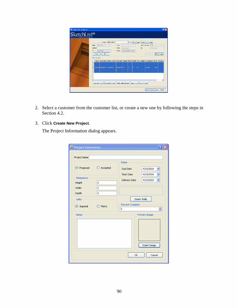
90
2. Select a customer from the customer list, or create a new one by following the steps in
Section 4.2.
3. Click Create New Project.
The Project Information dialog appears.

91
4. Type a name for the project in the Project Name box.
5. In the next pane, choose Proposed if the project has not yet been accepted by the
customer, or Accepted if it has been accepted.
This information may be used in later editions of SketchList to generate reports about
your business. It does not have any effects on your project design.
6. In the next pane, enter the total dimensions of the project.
As an example, if you‘re designing an L-shaped desk with a hutch on top of one side, the
height of the project would be the total height of the desk plus the total height of the
hutch. If the two lengths of the L are 60 inches and 30 inches, the total width and depth of
the project would be 60 by 30.
7. In the Units pane, choose Imperial or Metric.
SketchList 3D remembers the units you chose and uses them throughout the project.
8. In the Dates pane, enter the due date, the start date, and the delivery date.
9. Click OK to exit the wizard and start designing your project.
9.3 Saving a project
Computers can crash at any time, so it‘s a good idea to save your projects fairly frequently. You
can use any of the following methods to save a project:
Choose File > Save Project.
Type Ctrl-S. (Hold down the Control key and press the S key.)
Click the Save Project button in the Control area.
9.4 Opening a saved project
To open a project that you previously saved:
1. Choose File > New/Open Project.
The Project Set-Up Wizard appears.

92
2. Choose a customer from the list.
3. Select the project you want from the Select a Project pane.
4. Click Load Selected Project.
Choose a customer here…. then choose a project from this list…
…and then click here.

93
9.5 Viewing projects
When you open a project, it appears in the Views area of the SketchList 3D main window in all
the views you have open. For more information about views and the Views area, see Section
5.3, The Views area.
At the project level, there is always a floor visible under the project.
9.6 Producing a 3D photo rendering of a project
SketchList 3D allows you to produce a 3D photo rendering of a project to get a better look at
your design, particularly edges. Whatever appears in the Perspective view will be rendered. You
can also set certain parameters for producing the rendering, such as the quality of the rendered
image, its width and height, and the background color.
To produce a 3D photo rendering:
1. Click 3D Photo-Render in the Control area.
The Photo Rendering dialog appears.
2. In the Set Quality pane, move the slider to set the quality of the rendering.

94
Moving the slider all the way to the left produces the lowest-quality rendering; all the
way to the right produces the highest quality. The quality also affects the speed of the
rendering: the higher the quality, the longer the rendering will take.
3. In the Image Parameters pane, use the sliders to choose a width and height for the image.
To keep the same width-to-height ratio as in the design, check the Keep original aspect
ratio box.
If you choose to keep the original aspect ratio, then moving the Image Width slider will
also move the Image Height slider, and vice versa. To move the sliders independently of
each other, first uncheck the Keep original aspect ratio box.
4. To change the background color, click Change and choose a new color from the Select
Color dialog that appears.
Consider how the material you are working with will appear against the background color
you select. If you are working with a light material—for example, a light maple—you
might want to go with a dark green background color for contrast. On the other hand, if
you‘re working with a dark material, you might choose a light or medium background
color to complement your work.
5. Click Render.
If you need to stop the rendering process, click Abort Rendering. Once rendering has finished,
you can save the rendered image, print it, or close the dialog by clicking the appropriate button
in the lower right part of the dialog.
The ability to save a graphic image is an important benefit of 3D photo rendering, because you
can paste these images into your customer proposals for best presentation purposes. SketchList
3D saves the image as a high-quality bitmap (BMP) file.

95
9.7 Importing and exporting projects
The ability to import and export projects allows you to share project with other SketchList 3D
users and to back up and recover your projects easily. The next two sections explain how to
import and export projects, respectively.
9.7.1 Importing a project
To import a project:
1. Choose File > Import/Export Project.
2. The Project Set-Up Wizard appears.
3. Click Import Project.
4. The Import Project dialog appears.
5. Navigate to the file you want to import and select it.
6. Click Open.
9.7.2 Exporting a project
To export a project:
1. Choose File > Import/Export Project.
2. The Project Set-Up Wizard appears.

96
3. Click Export Project.
4. The Export Project dialog appears.
5. Navigate to the folder where you want to save the file.
6. Enter a name for the file in the File name text box.
7. Click Save.
9.8 Backing up and restoring projects
You can use SketchList 3D‘s export and import capabilities to back up and restore your
projects. To back up a project, simply export it as described in Section 9.7.2. To restore a
project from backup, import it as described in Section 9.7.1.
9.9 Changing information about projects
You can use the Project Information dialog to change various attributes of a project, including
its name, size, units, and associated dates. To make these changes:
1. Choose Setup > Project Information.
The Project Information dialog appears.

97
2. Make the changes you want, and click OK.
9.10 Deleting a project
To delete a project, follow these steps:
1. If the project you want to delete is currently open, close it by choosing File > Close
Project.
2. Choose File > New/Open Project.
The Project Set-Up Wizard appears.
3. Select the project you want to delete.
4. Click Delete Selected Project.


99
10
Working with Assemblies
This chapter explains what assemblies are and how to manage them.
10.1 What is an assembly?
An assembly is a subpart of a project.
One advantage of using assemblies is that an assembly allows you to manage a group of
components at one time. For example, if you have a bookshelf assembly made up of 20 boards,
you can simultaneously move all 20 boards ten inches to the left by moving the assembly once.
Another advantage of using assemblies is that you can replicate or clone them. For example, if
you are designing a kitchen, you can design a standard cabinet and clone it the required number
of times.
One place where you may need to be careful in using assemblies is in associating two or more
boards in two different assemblies. Associating boards across assemblies requires the mental
mathematics of locating the boards via the common point of the frontmost, bottommost,
leftmost corner of the project.
10.2 Switching from the project level to the assembly level
Most of the features in this chapter require you to be at the assembly level. To move from the
project level (or another level) to the assembly level:
Click Assembly Level in the Hierarchical Levels dialog.
Click here.

100
10.3 Adding an assembly to a project
10.3.1 Creating a new assembly
To add an assembly to a project:
1. Make sure you are at the project level.
2. Do one of the following, depending on your preference:
Select Insert > New > Assembly.
Click the Insert Assembly icon in the Control area.
10.3.2 Inserting a standard assembly
You can insert an assembly that was created in another project if that assembly was saved as a
standard assembly in the original project. For more information on saving an assembly as a
standard assembly, see Section 10.11.
To insert a standard assembly:
1. Make sure you are at the project level.
2. Choose Insert > Standard > Assembly.
The Standard Assemblies dialog appears.
3. Select the standard assembly you want from the list in the dialog.

101
4. Click OK.
10.4 Locating an assembly within a project
To add an assembly to a project:
1. Make sure you are at the project level.
You can check or change your level in the Hierarchical Levels area.
2. Do one of the following, depending on your preference:
Click the assembly you want in the project spreadsheet.
Click the assembly in the Views area.
The assembly you chose becomes the active assembly.
10.5 Viewing an assembly
When you open an assembly, it appears in the Views area of the SketchList 3D main window in
all the views you have open. For more information about views and the Views area, see Section
5.3, The Views area.
Unlike the project area, the assembly level does not display a floor under the project.
10.6 Viewing a different assembly within the same project
To move to a different assembly:
1. Make sure you are at the project level.
You can check or change your level in the Hierarchical Levels area.
2. Do either of the following, depending on your preference:
Click the assembly you want in the Views area.
In the Project Spreadsheet or the General Spreadsheet, click the assembly you want.
10.7 Moving an assembly within a project
You can reposition an assembly within a project. However, when you do this, you must be sure
that after the assembly has been relocated, the entire assembly still fits within the dimensions of
the project. If any part of the assembly falls outside the project dimensions, the assembly‘s row
in the Project Spreadsheet turns red and blinks, as do the buttons in the Assembly Form. You
can find out the project dimensions from the Control area.

102
To reposition an assembly within a project:
1. Make sure you are at the project level.
You can check or change your level in the Hierarchical Levels area.
2. Select the assembly within the Project Spreadsheet or the Views area.
3. In the Project Spreadsheet or the Assembly Form, change the location values—Top,
Bottom, Front, and so on—as desired.
10.8 Changing the size of an assembly
You can change the size of an assembly at any time. However, when you do this, you must be
sure that after the assembly has been resized, the entire assembly still fits within the dimensions
of the project. If any part of the assembly falls outside the project dimensions, the assembly‘s
row in the Project Spreadsheet turns red and blinks, as do the buttons in the Assembly Form.
You can find out the project dimensions from the Control area.
To change the size of an assembly:
1. Make sure you are at the project level.
You can check or change your level in the Hierarchical Levels area.
2. Select the assembly within the Project Spreadsheet or the Views area.
3. In the Project Spreadsheet or the Assembly Form, change the dimensions as desired.
4. Adjust the location values—Top, Right, and so on—as required.
10.9 Cloning an assembly
Cloning allows you to make an exact copy of an assembly so that you can reuse the assembly
within a project. This is helpful when you are designing a project that reuses the same elements
over and over, such as kitchen cabinets or a set of built-in bookcases in a home library. For
information on how to use an assembly in a different project, see Section 10.11, Saving an
assembly as a standard assembly, and Section 10.3.2, Inserting a standard assembly.
You can either clone an assembly and reposition it manually within the project, or you can
specify the number of clones and have SketchList 3D space them out. These procedures are
described in Sections 10.9.1 and 10.9.2, respectively.
10.9.1 Simple cloning
Simple cloning makes one copy of the selected assembly and positions it in exactly the same
location as the original assembly. When using this option, you will need to change the clone‘s
location by hand.

103
To make a single copy of an assembly:
1. Make sure you are at the project level.
You can check or change your level in the Hierarchical Levels area.
2. Select the assembly in the Views area or the Project Spreadsheet.
3. Right-click on the assembly or its spreadsheet row.
4. Select Clone from the drop-down menu that appears.
Alternatively, you can click Clone in the Assembly Form.
The new assembly appears in the Project Spreadsheet with (Clone1) added to its name.
5. Edit the cloned assembly‘s location information in the Project Spreadsheet or the
Assembly Form.
10.9.2 Cloning and spacing
You can make more than one clone of an assembly at a time by using the Clone and Space
feature. Clone and Space also puts distance between the cloned assemblies, so that they aren‘t
located in exactly the same space as the original assembly.
You can clone any number of assemblies, but the cloned assemblies must all fit inside the
current project. For example, if you try to put four 30-inch wide assemblies in a project that is
100 inches wide, an error message appears.
To clone and space an assembly:
1. Make sure you are at the project level.
You can check or change your level in the Hierarchical Levels area.
2. Select the assembly in the Views area or the Project Spreadsheet.
3. In the Assembly Form, click Clone and Space.
You may have to scroll down to see this button.

104
The Clone & Space dialog appears.
Click here.

105
4. In the Unique Name text box, enter a name for the cloned assembly.
The assembly in the figure above is named Lower. If you clone it three times, the cloned
assemblies are named Lower(Clone1), Lower(Clone2), and Lower(Clone3).
5. In Number of Cloned Boards, enter the number of times you want to clone the assembly
(that is, the total number of assemblies minus 1 for the existing assembly).
The next step is specifying how to space the assemblies. You have two choices: You can
specify the location of the final cloned assembly (Determine Spacing), or you can specify
the distance between each of the assemblies (Fixed Space).
6. Select Determine Spacing or Fixed Space.
7. If you chose Determine Spacing, enter the Left, Front, and Bottom values for the final
assembly.
As an example, let‘s say you‘re cloning an assembly that is 20 inches wide in a 60 inch
project. The Left value of the final cloned assembly cannot be greater than 40 inches
(that is, the limit of the project minus the width of the assembly, or 60 – 20 inches). If
you enter a Left value greater than 40, an error message appears.
You can set Left, Front, and Bottom values in any combination. This allows you to clone
an assembly moving it from left to right, front to back, and bottom to top at the same
time. This is useful if, for example, you‘re designing a spiral staircase.
8. If you chose Fixed Spacing, specify the distance between each assembly.
In the example below, which uses boards, the cloned board was set at a distance of 5
inches from the original. The bottom of the cloned board is 5¾ inches from the bottom of
the original board. Subtracting the ¾-inch thickness of the board original, the spacing
between the two boards is 5 inches.

106
10.10 Producing a 3D photo rendering of an assembly
SketchList 3D allows you to produce a 3D photo rendering of an assembly to get a better look at
your design, particularly edges. Whatever appears in the Perspective view will be rendered. You
can also set certain parameters for producing the rendering, such as the quality of the rendered
image, its width and height, and the background color.
To produce a 3D photo rendering:
1. Make sure you are at the project level.
You can check or change your level in the Hierarchical Levels area.
2. Select the assembly you want to render.
3. Click 3D Photo-Render in the Control area.
The Photo Rendering dialog appears.
4. In the Set Quality pane, move the slider to set the quality of the rendering.
Moving the slider all the way to the left produces the lowest-quality rendering; all the
way to the right produces the highest quality. The quality also affects the speed of the
rendering: the higher the quality, the longer the rendering will take.

107
5. In the Image Parameters pane, use the sliders to choose a width and height for the image.
To keep the same width-to-height ratio as in the design, check the Keep original aspect
ratio box.
If you choose to keep the original aspect ratio, then moving the Image Width slider will
also move the Image Height slider, and vice versa. To move the sliders independently of
each other, first uncheck the Keep original aspect ratio box.
6. To change the background color, click Change and choose a new color from the Select
Color dialog that appears.
Consider how the material you are working with will appear against the background color
you select. If you are working with a light material—for example, a light maple—you
might want to go with a dark green background color for contrast. On the other hand, if
you‘re working with a dark material, you might choose a light or medium background
color to complement your work.
7. Click Render.
If you need to stop the rendering process, click Abort Rendering. Once rendering has finished,
you can save the rendered image, print it, or close the dialog by clicking the appropriate button
in the lower right part of the dialog.
The ability to save a graphic image is an important benefit of 3D photo rendering, because you
can paste these images into your customer proposals for best presentation purposes. SketchList
3D saves the image as a high-quality bitmap (BMP) file.
10.11 Saving an assembly as a standard assembly
You can save an assembly as a standard and use it in other projects. This section explains how
to save an assembly as a standard; for information on using a standard assembly, see Section
10.3.2.

108
To save an assembly as standard:
1. Make sure you are at the project level.
You can check or change your level in the Hierarchical Levels area.
2. Choose a precise, descriptive name for the standard assembly.
For example, the name Left may not be very helpful in several months when you want to
use the assembly again. It‘s better to be more precise—for instance, Left Three-Shelf
Bookcase.
3. Enter the new name in the Unique Name text box in the Assembly Form.
4. Click Make Standard.
You may have to scroll down in the Assembly Form to see this button.
A message box will open verifying the creation of the standard assembly.
5. Click OK.
10.12 Deleting assemblies
There are several ways to delete an assembly. Select the assembly you want to delete and use
the most convenient of the following methods:
Right-click in the Views area and choose Delete selected.
Right-click on the assembly‘s row in the Project Spreadsheet and choose Delete.
Click the Delete button in the Assembly Form.
Press the Delete key on your computer keyboard.
To undo a deletion that you just did, click the Undo button in the Control area or press
Control-Z on your keyboard.

109
Part 3
Working with Specific Types of
Components


111
11
Working with Boards
This chapter describes tasks and procedures that are specific to working with square and
rectangular boards.
11.1 What is a board?
A board is a three-dimensional component within a SketchList 3D assembly. It may consist of
any material, although most SketchList 3D users will be working with wood.
Each board is assigned a color, grain texture, and transparency, and you can change these
properties to define metal, glass, stone, plastic, or even paper components as the need arises. For
example, you can create a ―board‖ made of material such as glass or stone to take the place of a
window or countertop in your assembly.
A board is always created with four edges and two surfaces.
11.2 Adding a board to an assembly
You can add, or insert, boards into assemblies, into drawers, or as doors. To insert a board:
1. In the Hierarchical Levels area, choose the level where you want to insert the board.
That is, click Assembly Level, Door Level, or Drawer Level.

112
2. Click Insert Board in the icon bar or choose Insert > New > Board.
3. The Set-Up Orientation, Material, and Dimensions of Board dialog (or Set-Up Board
dialog, for short) opens on your screen.
4. In the Choose Material pane, choose a material for your board.
If the Choose Material pane is too small, click Expand to make it larger. After you choose
a material, click Shrink to display the Set-Up Board dialog again.
Each material has the following characteristics. Some materials may be almost the same
except for one or two characteristics—for example, supplier and cost. Scroll to the right
to see all the characteristics for a material.
Material type. Some examples of material type are sheet goods, dimensioned lumber,
or miscellaneous.
Material name.
Grain direction. This characteristic indicates whether the grain direction is in line
with the width or the length of the source material.
Transparency. The transparency of the material can be anywhere from 0 (opaque) to
100 (completely transparent).

113
Metric. This characteristic indicates whether the metric or imperial system was used
to create the board.
Thickness. This characteristic refers to the thickness of the material.
Width. This refers to the width of the source material. In a 48 x 96 sheet of plywood,
the width is 48.
Length. This refers to the length of the source material. In a 48 x 96 sheet of
plywood, the length is 96.
Units. This is terminology referring to the board. In the materials database that comes
with SketchList 3D, units can be Pieces or Sheets.
Cost per unit. This is the cost of each piece of material. It is used to determine the
total materials cost for the job. SketchList 3D does not automatically update costs.
Currency. The currency in which the total materials cost will be determined.
Cost last update date. This is the last time the cost for the material was updated. It
allows you to ensure that your materials cost information is current.
Units on hand. This is a manual count of the number of pieces of the material you
have in your inventory. SketchList 3D does not automatically update this count.
Supplier. This refers to the supplier for the material. It is possible to have two
materials that are exactly the same except for supplier and cost. When you select the
materials to create the board, you can select the material by supplier.
Notes. This contains any notes relevant to the material.
5. Select an orientation for the board by clicking one of the images in the Orientation of
Board pane.
The orientations are:
Width. The side of a bookcase is an example of a board with an orientation of width.
Height. A shelf is an example of a board with an orientation of height.
Depth. The back of a cabinet is an example of a board with an orientation of depth.

114
6. Under the orientation you chose, enter values for the board‘s size.
Each of the three orientations has a different terminology for the size of the board, as
follows:
Width uses Height and Depth, because the board is thought of as being high and deep.
Height uses Width and Depth, because the board is thought of as having a width
across the front and a depth into the assembly.
Depth uses Height and Width, because the board is thought of being high and wide.
Note: When you‘re placing a board—for example, between two other boards—and
don‘t know the exact size of the space you‘re placing it into, it‘s sometimes faster just
to guess at the dimensions of the board, erring on the small side. Once the board is in
place and you can see the dimensions of the boards it relates to in the spreadsheet,
you can size the new board more precisely.
7. Choose a grain direction for the board.
Choosing a grain direction is important for two reasons. The first is that when you review
your work, especially in photorealistic mode, the direction of the grain enhances and even
verifies your design. The second is that, in order to run the material layout optimizer,
SketchList 3D must match the grain direction of the board with the grain direction of the
material from which the board will be cut.
You can choose None for the grain direction if you are working with a material that
doesn‘t have a grain—for example, MDF—or you don‘t care about the grain direction.
The advantage of no grain direction is that, since the optimizer has no limits for matching
grain direction, there may be less wasted material.
After you enter the board‘s dimensions and select the grain direction, the board is shown
in the Board Orientation on Material pane. This allows you to verify that you have the
right size and orientation, and that the board fits on the material in the given grain
direction. You can see immediately if the board is too large for the material, in which
case you will need to enter a different size for the board or select another material.
8. Click OK.
If the board is larger than the current assembly, an error message appears, and you will
need to resize either the board or the assembly. The next section explains how to resize a
board. For instructions on resizing an assembly, see Section 10.8, Changing the size of an
assembly.
11.3 Changing the size of a board
You can change the size of a board at any time. However, when you do this, you must be sure
that after the board has been resized, it still fits within the dimensions of the assembly it belongs
to. If any part of the board falls outside the assembly‘s dimensions, the board‘s row in the
Assembly Spreadsheet turns red and blinks, as do the buttons in the Board Form. You can find
out the assembly dimensions from the Control area.

115
Note: Once a material has been set up at a specific thickness, that thickness cannot be changed.
If you are working with a material that is 1 inch thick, and you want a board that is ¼ inch thick,
clone the original board (see Section 11.7, Cloning a board) and set the thickness of the cloned
board to ¼ inch.
Caution: If you try to change a board with attributes such as contours, joinery, or a shape, a
warning appears stating that the results of the changed board may not be what you expect. For
example, if you shape a board to have a 45° cut in it, and you resize that board, the beginning
and ending locations of the cut may not be where you expect and should be checked after the
change is made.
To change the size of a board:
1. Make sure you are at the level that contains the board—Assembly, Door, or Drawer.
You can check or change your level in the Hierarchical Levels area.
2. Select the board within the Spreadsheet or the Views area.
3. In the Spreadsheet or the Board Form, change the board‘s dimensions as desired.
4. Adjust the location values—Top, Right, and so on—as required.
11.4 Changing the material, orientation, or grain direction of a board
To change the material, orientation, or grain direction of a board:
1. Make sure you are at the level that contains the board—Assembly, Door, or Drawer.
You can check or change your level in the Hierarchical Levels area.
2. Select the board within the Spreadsheet or the Views area.
3. In the Board Form, click Choose Orientation and Material.
The Set-Up Board dialog appears.

116
4. Make the changes you require.
For detailed instructions, see Section 11.2.
5. When you are finished, click OK.
11.5 Changing the edges of a board
SketchList 3D allows you to add joinery and contours to the edges of boards. For more
information, see Chapters 13 and 15, respectively.
11.6 Adding holes to a board
With SketchList 3D, you can drill or cut a hole into either a surface or an edge of a board. A
drilled hole is called a round hole. Any type of slot that you might cut into a board is called a
non-round hole. A hole can be drilled or cut the entire thickness of a material, unless such a cut
would create two individual boards from the original.
You can add contours to the cut edges of the hole. For instructions on adding contours, see
Chapter 13.
A hole is not allowed to touch or otherwise cross the edge of another hole.
11.6.1 Adding a round hole to a board
A round hole‘s size is determined by its diameter and its depth of cut. The diagram on the next
page shows 1-inch diameter hole drilled through the entire depth of a 2 inch board. The hole is 3
inches from one edge (A) and 5 inches from the other edge (B).

117
To add a round hole to a board:
1. Make sure you are at the level that contains the board—Assembly, Door, or Drawer.
You can check or change your level in the Hierarchical Levels area.
2. Select the board within the Spreadsheet or the Views area.
3. In the Board Details Spreadsheet, select the surface or edge to which you want to add the
hole.
4. In the Board Details Form, click Holes.
You may have to scroll down to see this button.
The Hole dialog appears.
Scroll down even further.

118
5. In the Name/ID box, enter a name for the hole.
6. In the Units pane, select the units you want to use.
7. In the Location pane, enter the hole‘s distance from the edges of the board.
8. In the Dimension pane, enter the hole‘s diameter and depth.
9. In the diagram in the center of the dialog, check that the hole is the correct size and is at
the correct location.
10. Enter any notes about the hole in the Notes box—for example, its intended purpose in the
design.
11. Click OK.
11.6.2 Adding a non-round hole to a board
The size of a non-round hole is specified by the height and width of the hole. The following
diagram shows a non-round hole that is 1 inch high (H) and 5 inches wide (W) and is cut
through the entire depth of the board (3/4 inch). The hole is 4 inches from one edge of the board
(A) and 2.5 inches from the other edge of the board (B). In the case of non-round holes, the
distances are from the left edge and bottom edge of the hole to be cut.
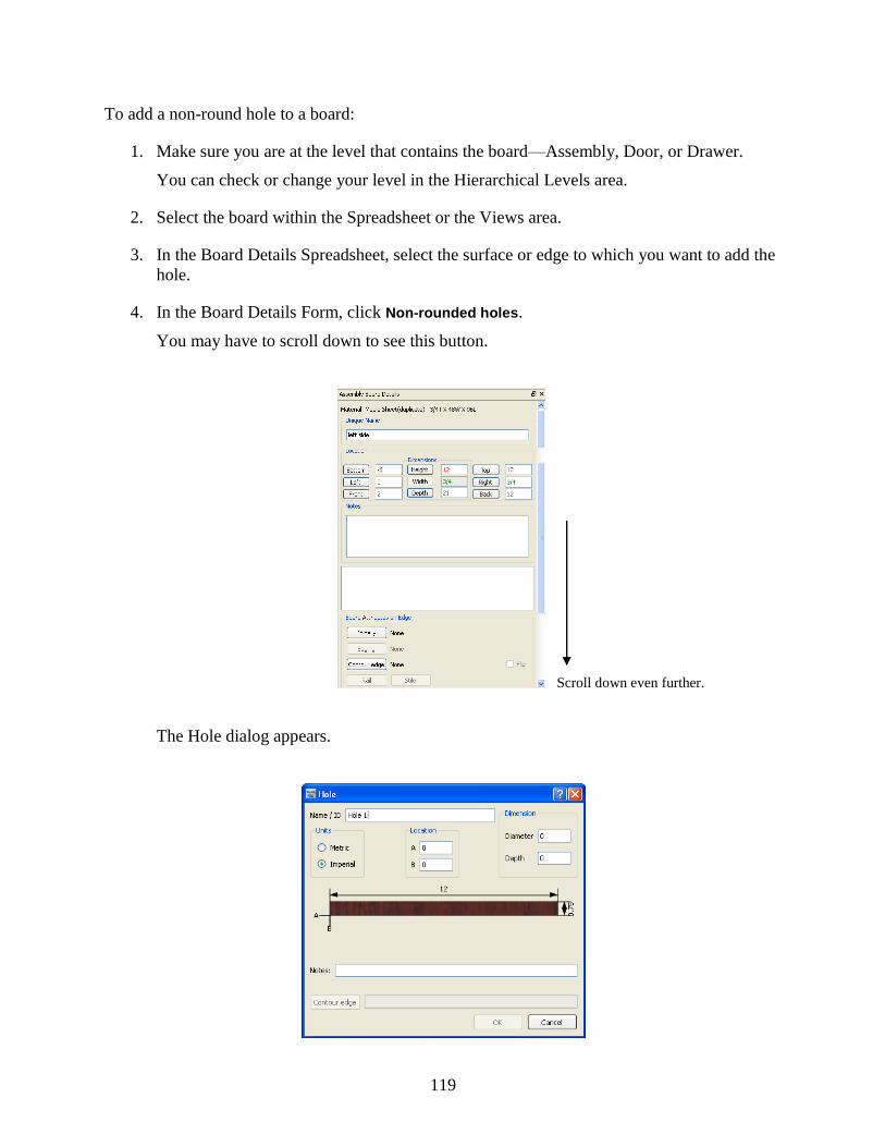
119
To add a non-round hole to a board:
1. Make sure you are at the level that contains the board—Assembly, Door, or Drawer.
You can check or change your level in the Hierarchical Levels area.
2. Select the board within the Spreadsheet or the Views area.
3. In the Board Details Spreadsheet, select the surface or edge to which you want to add the
hole.
4. In the Board Details Form, click Non-rounded holes.
You may have to scroll down to see this button.
The Hole dialog appears.
Scroll down even further.

120
5. In the Name/ID box, enter a name for the hole.
6. In the Units pane, select the units you want to use.
7. In the Location pane, enter the hole‘s distance from the edges of the board.
8. In the Dimension pane, enter the hole‘s diameter and depth.
9. In the diagram in the center of the dialog, check that the hole is the correct size and is at
the correct location.
10. Enter any notes about the hole in the Notes box—for example, its intended purpose in the
design.
11. Click OK.
11.6.3 Changing a hole in a board
To change a hole in a board:
1. Make sure you are at the level that contains the board—Assembly, Door, or Drawer.
You can check or change your level in the Hierarchical Levels area.
2. Select the board within the Spreadsheet or the Views area.
3. In the Board Details Form, click Holes Spreadsheet.
You may have to scroll down to see this button.
The Holes Spreadsheet appears.
In this spreadsheet, round holes have no value in the Height and Width cells, and non-
round holes have no value in the Diameter cell.
4. Right-click on the hole you want to change.
5. Choose Edit from the pop-up menu.
The Hole dialog appears.

121
6. Make the changes you want and click OK.
11.6.4 Cloning a hole
To clone a hole in a board:
1. Make sure you are at the level that contains the board—Assembly, Door, or Drawer.
You can check or change your level in the Hierarchical Levels area.
2. Select the board within the Spreadsheet or the Views area.
3. In the Board Details Form, click Holes Spreadsheet.
You may have to scroll down to see this button.
The Holes Spreadsheet appears.
4. Right-click on the hole you want to clone.
5. Choose Clone from the pop-up menu.
A new row appears in the Holes Spreadsheet, with _Cloned at the end of the original
hole‘s name.
11.6.5 Deleting a hole from a board
To delete a hole:
1. Make sure you are at the level that contains the board—Assembly, Door, or Drawer.
You can check or change your level in the Hierarchical Levels area.
2. Select the board within the Spreadsheet or the Views area.
3. In the Board Details Form, click Holes Spreadsheet.
You may have to scroll down to see this button.
The Holes Spreadsheet appears.

122
4. Right-click on the hole you want to delete.
5. Choose Delete from the pop-up menu.
11.7 Cloning a board
When you clone a board, you make an exact copy of the board, complete with any trim, joinery,
edging, or other details you‘ve added to the original board. Cloning a board is much faster than
creating the same board design from scratch, so if you need to reuse a board design in a project,
cloning the boards can save you a lot of time.
You can clone boards in each direction—horizontally, vertically, and depth-wise. You can even
stagger board clones in two or three directions, as if you were building a staircase.
The following subsections describe two different ways to clone boards. You can use the way
that‘s most convenient or appropriate for your project.
11.7.1 Simple cloning
If you only need to clone a board once, or if you want to adjust the location of your cloned
boards manually, follow these steps:
1. Select the board you want to clone.
2. Right-click the board and choose Clone selected.
The new board appears in the Assembly spreadsheet, but won‘t be visible in the Views area,
because it occupies exactly the same space as the original board. You can move it to a new
position by changing its location in the Assembly Spreadsheet.
11.7.2 Cloning and spacing
To create multiple cloned boards at the same time and space them out automatically:
1. Select the board you want to clone.
2. In the Board Form, click Clone&Space.
The Clone & Space dialog appears.

123
3. In the Unique Name box, enter a name for the cloned boards.
Each of the cloned boards will have this name with ―(cloneX)‖ at the end, where X is a
number. For example, if you enter ―Right Board‖ as the name, the cloned board will be
named ―Right Board(clone1)‖.
4. Select the number of cloned boards you want.
You can make up to 99 clones at one time.
5. Specify the spacing between the boards.
If you know the location of the final cloned board in the group and want SketchList 3D to
determine the spacing for you, click Determine spacing and enter the Left, Front, and
Bottom values for the final board‘s location.
SketchList 3D spaces the boards equally between the location of your original board and
the location of your final board.
If you want a fixed space between the boards, select Fixed Space and enter the amount of
space between each board. Then select whether you want the cloned boards to be placed
to the left, front, or bottom of the original board.
SketchList 3D positions the boards with the specified amount of space between each one.
11.8 Deleting a board
There are several ways to delete a board. Select the board you want to delete and use the most
convenient of the following methods:
Right-click in the Views area and choose Delete selected.

124
Right-click on the board‘s row in the Spreadsheet and choose Delete.
Click the Delete button in the Board Details Form.
Press the Delete key on your computer keyboard.
To undo a deletion that you just did, click the Undo button in the Control area or press
Control-Z on your keyboard.

125
12
Working with Joinery
Sketch list 3D allows you to put joinery types on any of the four edges of a board. By default,
boards start off in SketchList 3D without any joints. This chapter explains how to add, remove,
and change joinery on a board edge.
12.1 Adding joinery
12.1.1 Planning joinery
Adding joinery to a board involves some planning before you start work in SketchList 3D. This
planning process may already be familiar to you from your experience with designing on paper;
it involves the following three decisions:
The type of joint you want. Section 12.1.2 lists the types of joints available in SketchList
3D.
The dimensions of the joint—for example, the angle for a miter. Section 12.1.3 describes
the dimensions you need for each type of joint.
A key concept for several types of joints is ―lengthened by,‖ which refers to the
difference between the design length and the cut length of the board. For example, if you
have a board that is 12 inches long, and you add two ¼-inch tenons to the board, the cut
length of the board becomes 12½ inches, while the design length remains at 12 inches.
The following diagram illustrates this.
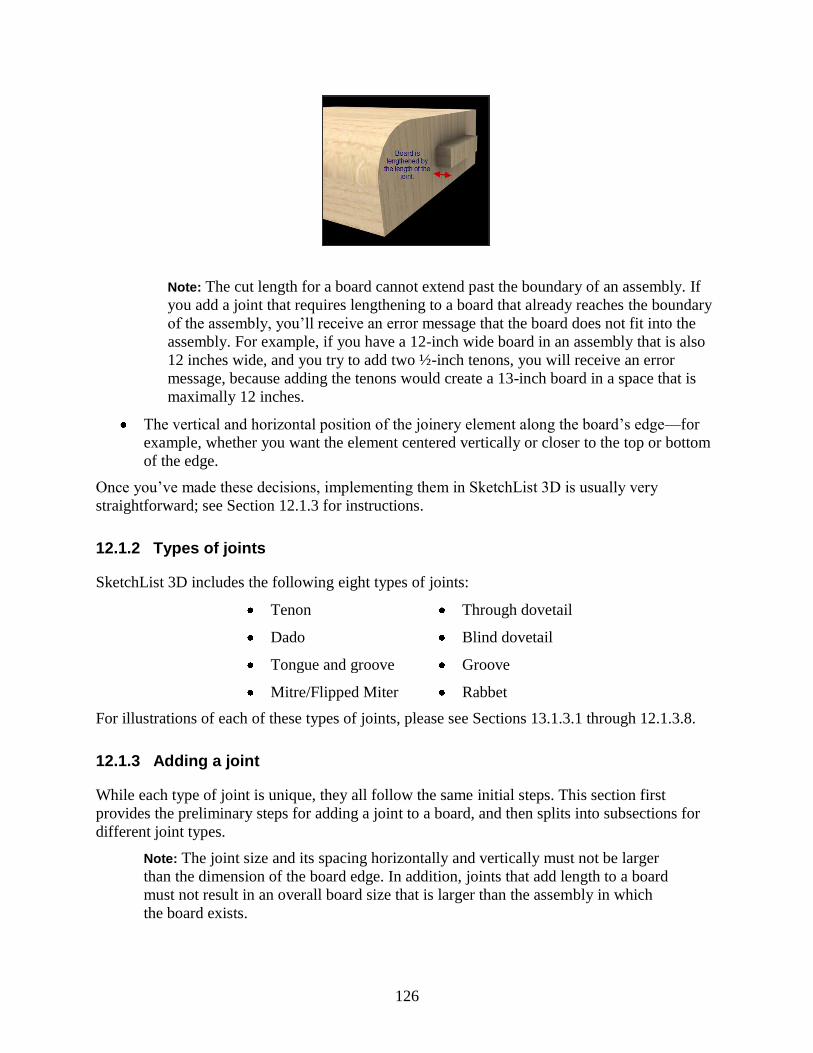
126
Note: The cut length for a board cannot extend past the boundary of an assembly. If
you add a joint that requires lengthening to a board that already reaches the boundary
of the assembly, you‘ll receive an error message that the board does not fit into the
assembly. For example, if you have a 12-inch wide board in an assembly that is also
12 inches wide, and you try to add two ½-inch tenons, you will receive an error
message, because adding the tenons would create a 13-inch board in a space that is
maximally 12 inches.
The vertical and horizontal position of the joinery element along the board‘s edge—for
example, whether you want the element centered vertically or closer to the top or bottom
of the edge.
Once you‘ve made these decisions, implementing them in SketchList 3D is usually very
straightforward; see Section 12.1.3 for instructions.
12.1.2 Types of joints
SketchList 3D includes the following eight types of joints:
Tenon Through dovetail
Dado Blind dovetail
Tongue and groove Groove
Mitre/Flipped Miter Rabbet
For illustrations of each of these types of joints, please see Sections 13.1.3.1 through 12.1.3.8.
12.1.3 Adding a joint
While each type of joint is unique, they all follow the same initial steps. This section first
provides the preliminary steps for adding a joint to a board, and then splits into subsections for
different joint types.
Note: The joint size and its spacing horizontally and vertically must not be larger
than the dimension of the board edge. In addition, joints that add length to a board
must not result in an overall board size that is larger than the assembly in which
the board exists.

127
To add joinery to a board:
1. At the Assembly Level, select the board you want to add joinery to.
You can check or change your level in the Hierarchical Levels area.
2. In the Hierarchical Levels area, click Board Details Level.
You can also click Board Details in the Board area. The board you selected appears by
itself in the Views area.
3. In the spreadsheet area, select the edge you want to add joinery to.
The edge turns green in the Views area. You can use the color and the orientation hints to
check that you have the edge you want.
4. In the Assembly Board Details area, under Board Attributes on Edge, click Joinery.
If your screen or the SketchList 3D window is small, you may need to scroll down to see
this button.
After you click the Joinery button, the Joinery Edging dialog appears.

128
5. Select the type of joint you want from the Type (Image/Name) list.
The instructions from this point on depend on the type of joint you want to apply. The next
sections describe the types of joints and how to add each one to a board.
12.1.3.1 Tenon
A tenon is a small section that extends past the end of a board. A tenon is generally inserted into
a mortise (cavity) in another board. Figure 12.1 shows a tenon as it looks in the Joinery Edging
dialog in SketchList 3D and as it would look on a board.
Figure 12.1 Tenon

129
You can specify the dimensions of the tenon and its vertical and horizontal offsets from the
bottom and left of the board edge.
To add a tenon:
1. Enter the length of the tenon as a decimal in the Lengthen By box.
This value determines the difference between the design length and the cut length of the
board.
2. Enter any information you want to remember in the Note box.
You can control the position of the tenon relative to the bottom and left of the board edge
by using the Vertical Position and Horizontal Position panes. The Vertical Position pane
allows you to specify the distance between the bottom of the tenon and the bottom of the
board edge. The Horizontal Position pane allows you to specify the distance between the
edge of the tenon and the left side of the board.
3. To position the tenon vertically:
To center the tenon, click Center in the Vertical Position pane and enter the height of
the tenon.
For example, to center a 3/8-inch high tenon vertically on the board edge, click
Center and enter 0.375 in the Joinery Height box.
To offset the tenon, click Vertical Offset and enter the vertical offset and the height of
the tenon.
4. To position the tenon horizontally:
To center the tenon, click Center in the Horizontal Position pane and enter the length
of the tenon.
For example, to place a two-inch long tenon centered on a board, click Center and
enter 2 in the Joinery Length box.
To offset the tenon, click Horizontal Offset and enter the horizontal offset and the
length of the tenon.
For example, to offset the tenon by 2 inches from the edge of the board, click
Horizontal Offset and enter 2 in the Horizontal Offset box.
5. Click OK.
12.1.3.2 Tongue and groove
A tongue is essentially a tenon that extends the whole width of the board edge. Figure 12.2
shows a tongue as it looks in the Joinery Edging dialog in SketchList 3D and as it would look on
a board.

130
Figure 12.2 Tongue and groove
You can specify the dimensions of the tongue and its vertical offset from the bottom of the
board edge.
To add a tongue:
1. Enter the length of the tongue as a decimal in the Lengthen By box.
This value determines the difference between the design length and the cut length of the
board.
2. Enter any information you want to remember in the Note box.
You can control the position of the bottom of the tongue relative to the bottom of the
board edge by using the Vertical Position pane. (There is no Horizontal Position pane
because the tongue runs the full width of the board edge.)
3. To position the tongue vertically:
To center the tongue, click Center in the Vertical Position pane and enter the height of
the tongue.
For example, to center a 3/8-inch thick tongue vertically on the board edge, click
Center and enter 0.375 in the Joinery Height box.
To offset the tongue, click Vertical Offset and enter the vertical offset and the height
of the tongue.
4. Click OK.
12.1.3.3 Miter and Miter Flipped
A miter is a beveled edge on a board. If you choose Miter from the Type list, the bevel starts at
the top of the board, as shown in Figure 12.3-A. To have the bevel start at the bottom of the
board, as in Figure 12.3-B, choose Miter Flipped from the Type list. The instructions for the
miter and the flipped miter are otherwise the same.

131
Figure 12.3-A Miter
Figure 12.3-B Miter Flipped
You can specify the angle and length of the miter and its horizontal offset from the bottom or
top of the board edge.
To add a miter:
1. In the V1 box, enter the distance from the bottom (or top) of the board to the edge of the
miter—the point where the bevel begins.
2. In the A box, enter the angle for the miter as a decimal.
3. Enter any information you want to remember in the Note box.
You can choose to have the miter run the full width of the board, or you can offset the
miter horizontally from the left side of the board edge.
4. To position the miter horizontally:
To have the miter run the full width of the board, enter 0 in the Horizontal Offset box
and the board‘s width in the Joinery Length box.
To offset the miter from the left corner of the board, enter the horizontal offset and
the length of the miter.
SketchList 3D will calculate the distance from the right edge of the miter to the right
edge of the board based on the values you enter for the horizontal offset and the
length of the miter.
As an example, assume you are working with a 24-inch board. To start the bevel 2
inches from the left side of the board edge, enter 2 in the Horizontal Offset box. If
you then enter 20 in the Joinery Length box, SketchList 3D will add a 2-inch offset

132
on the right side of the bevel as well (24‖ board – 2‖ offset – 20‖ bevel = 2‖
remaining)
5. Click OK.
12.1.3.4 Dado
A dado is a slot cut into a board edge. Figure 12.4 shows a dado as it looks in the Joinery
Edging dialog in SketchList 3D and as it would look on a board.
Figure 12.4 Dado
You can specify the thickness of the slot and the depth of the cut—the distance into the board
the cut will be made. You can also control the vertical positioning of the slot on the board edge
by specifying values for the vertical height of the board above and below the cut. SketchList 3D
calculates the thickness of the cut by subtracting the vertical heights from the board thickness:
Thickness of cut = Board thickness – V1 – V2
As an example, if you are working with a one-inch board and set both V1 and V2 to 0.25, then
the thickness of the cut will be 0.5 (that is, 1 – (0.25 * 2)).
To add a dado:
1. In the Depth of Cut box, enter the depth of the cut into the board.
2. In the V1 box, enter the distance from the bottom of the board edge to the bottom of the
slot.
3. In the V2 box, enter the distance from the top of the board edge to the top of the slot.
4. Enter any information you want to remember in the Note box.
5. Click OK.
12.1.3.5 Through dovetail
Figure 12.5 shows a through dovetail as it looks in the Joinery Edging dialog in SketchList 3D
and as it would look on a board.

133
Figure 12.5 Through dovetail
You can specify the angle and length of the through dovetail and its thickness at its outer edge.
You can also specify its vertical and horizontal offsets from the bottom and left of the board
edge.
Currently, SketchList 3D supports only one dovetail per edge.
To add a through dovetail:
1. Enter the length of the dovetail as a decimal in the Lengthen By box.
This value determines the difference between the design length and the cut length of the
board.
2. In the A box, enter the angle at which the dovetail meets the board.
3. Enter any information you want to remember in the Note box.
You can control the position of the dovetail relative to the bottom and left of the board
edge by using the Vertical Position and Horizontal Position panes. The Vertical Position
pane allows you to specify the distance between the bottom of the dovetail and the
bottom of the board edge. The Horizontal Position pane allows you to specify the
distance between the left edge of the dovetail and the left side of the board edge.
4. To position the dovetail vertically:
To center the dovetail, click Center in the Vertical Position pane.
To offset the dovetail, click Vertical Offset and enter the vertical offset.
5. To set the thickness of the dovetail at its outer edge, enter a value in the Joinery Height
box.
6. To position the dovetail horizontally:
To center the dovetail, click Center in the Horizontal Position pane and enter the
length of the dovetail.

134
For example, to place a two-inch long dovetail centered on a board, click Center and
enter 2 in the Joinery Length box.
To offset the dovetail, click Horizontal Offset and enter the horizontal offset and the
length of the dovetail.
For example, to offset a two-inch dovetail by 2 inches from the edge of the board,
click Horizontal Offset and enter 2 in both the Horizontal Offset box and the Joinery
Length box.
7. Click OK.
12.1.3.6 Blind dovetail
Figure 12.6 shows a blind dovetail as it looks in the Joinery Edging dialog in SketchList 3D and
as it would look on a board.
Figure 12.6 Blind dovetail
You can specify the angle and length of the blind dovetail and its thickness at its outer edge.
You can also specify its vertical and horizontal offsets from the bottom and left of the board
edge.
Currently, SketchList 3D supports only one dovetail per edge.
To add a blind dovetail:
1. Enter the length of the dovetail as a decimal in the Lengthen By box.
This value determines the difference between the design length and the cut length of the
board.
2. In the A box, enter the angle at which the dovetail meets the board.
3. Enter any information you want to remember in the Note box.
You can control the position of the dovetail relative to the bottom and left of the board
edge by using the Vertical Position and Horizontal Position panes. The Vertical Position
pane allows you to specify the distance between the bottom of the dovetail and the
bottom of the board edge. The Horizontal Position pane allows you to specify the
distance between the left edge of the dovetail and the left side of the board edge.

135
4. To position the dovetail vertically:
To center the dovetail, click Center in the Vertical Position pane.
To offset the dovetail, click Vertical Offset and enter the vertical offset.
5. To set the thickness of the dovetail at its outer edge, enter a value in the Joinery Height
box.
6. To position the dovetail horizontally:
To center the dovetail, click Center in the Horizontal Position pane and enter the
length of the dovetail.
For example, to place a two-inch long dovetail centered on a board, click Center and
enter 2 in the Joinery Length box.
To offset the dovetail, click Horizontal Offset and enter the horizontal offset and the
length of the dovetail.
For example, to offset a two-inch dovetail by 2 inches from the edge of the board,
click Horizontal Offset and enter 2 in both the Horizontal Offset box and the Joinery
Length box.
7. Click OK.
12.1.3.7 Groove
A groove is a cut in a board edge that does not run the full length of the edge. Figure 12.7 shows
a groove as it looks in the Joinery Edging dialog in SketchList 3D.
Figure 12.7 Groove
You can specify the height of the groove and the depth to which it extends into the board. You
can also control the horizontal positioning of the groove on the board edge.
To add a groove:
1. In the Depth of Cut box, enter the depth of the groove as a decimal.
2. In the V1 box, enter the height of the groove as a decimal.
3. Enter any information you want to remember in the Note box.
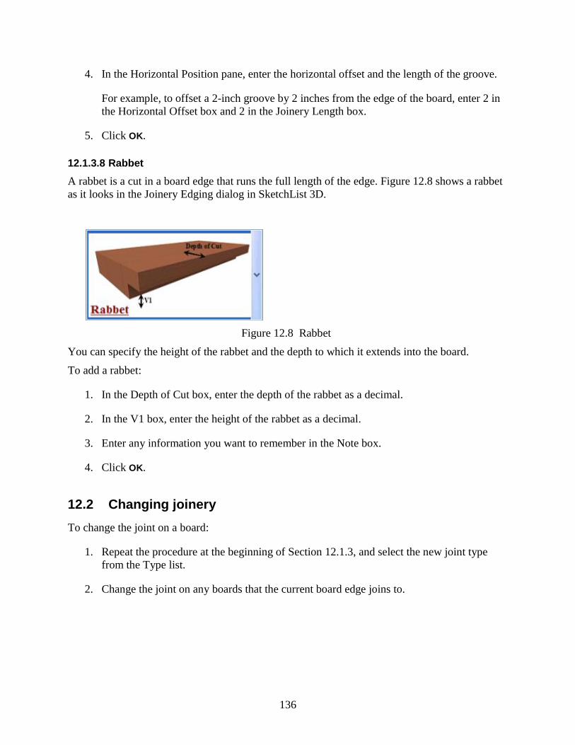
136
4. In the Horizontal Position pane, enter the horizontal offset and the length of the groove.
For example, to offset a 2-inch groove by 2 inches from the edge of the board, enter 2 in
the Horizontal Offset box and 2 in the Joinery Length box.
5. Click OK.
12.1.3.8 Rabbet
A rabbet is a cut in a board edge that runs the full length of the edge. Figure 12.8 shows a rabbet
as it looks in the Joinery Edging dialog in SketchList 3D.
Figure 12.8 Rabbet
You can specify the height of the rabbet and the depth to which it extends into the board.
To add a rabbet:
1. In the Depth of Cut box, enter the depth of the rabbet as a decimal.
2. In the V1 box, enter the height of the rabbet as a decimal.
3. Enter any information you want to remember in the Note box.
4. Click OK.
12.2 Changing joinery
To change the joint on a board:
1. Repeat the procedure at the beginning of Section 12.1.3, and select the new joint type
from the Type list.
2. Change the joint on any boards that the current board edge joins to.

137
12.3 Deleting joinery
To delete a joint:
1. Repeat the procedure at the beginning of Section 12.1.3, and select None from the Type
list.
2. Remove the joint on any boards that the current board edge joins to.


139
13
Working with Contours on Boards
By default, boards start off in SketchList 3D without any contours. This chapter explains how to
add, change, and delete contours on board edges, how to add crown molding to a board using
contours, and how to place contours on adjacent boards to create even more complex shapes.
13.1 Adding contours
13.1.1 Planning contours
Adding contours to a board involves some planning before starting to design. In particular, it
involves the following decisions:
The type of contour you want. Section 13.1.2 lists the types of contours available in
SketchList 3D.
The dimensions for each individual part of the contour. Each contour in SketchList 3D is
associated with a set of dimensions—for example, the radius of a rounded portion or the
vertical measurement for a straight portion. These measurements must add up in a certain
way that depends on the contour; this is discussed further for each contour type in Section
13.1.2.
The length of the contour and its offset from the two ends of the edge. The offset must be
the same on both sides of the contour, and the measurements must fit the following
equation:
(Offset * 2) + Length of contour = Length of edge
Once you‘ve made these decisions, implementing them in SketchList 3D is straightforward.
13.1.2 Types of contours
SketchList 3D includes the following six types of contours:
Roundover
Cove

140
Chamfer
V Groove
Bullnose
Roman (Ogee)
For illustrations of each of these contour types, please see Sections 13.1.3.1 through 13.1.3.6.
13.1.3 Adding a contour
To add a contour to a board:
1. At the Assembly Level, select the board you want to add the contour to.
You can check or change your level in the Hierarchical Levels area.
2. In the Hierarchical Levels area, click Board Details Level.
You can also click Board Details in the Board area. The board you selected appears by
itself in the Views area.
3. In the spreadsheet area, select the edge you want to add the contour to.
The edge turns green in the Views area. You can use the color and the orientation hints to
check that you have the edge you want.
4. In the Assembly Board Details area, click Contour edge.
If your screen or the SketchList 3D window is small, you may need to scroll down to see
this button. When you click it, the Contour Edging dialog appears.
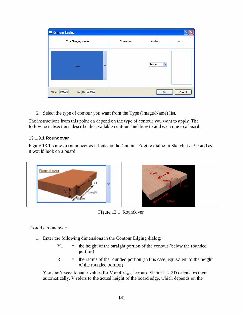
141
5. Select the type of contour you want from the Type (Image/Name) list.
The instructions from this point on depend on the type of contour you want to apply. The
following subsections describe the available contours and how to add each one to a board.
13.1.3.1 Roundover
Figure 13.1 shows a roundover as it looks in the Contour Edging dialog in SketchList 3D and as
it would look on a board.
Figure 13.1 Roundover
To add a roundover:
1. Enter the following dimensions in the Contour Edging dialog:
V1 = the height of the straight portion of the contour (below the rounded
portion)
R = the radius of the rounded portion (in this case, equivalent to the height
of the rounded portion)
You don‘t need to enter values for V and Vcalc, because SketchList 3D calculates them
automatically. V refers to the actual height of the board edge, which depends on the

142
material you chose for the board, and Vcalc refers to the height of the contour as
calculated by adding V1 + R. Vcalc must equal V.
As an example, if you are using a 0.75-inch board and set the radius, R, to 0.5 inch, then
the vertical offset—the flat area, or V1—has to be 0.25 inch, because V1 + R must equal
V.
2. Enter any information you want to remember in the Note box.
3. Position the contour on the board edge by entering values in the Offset and Length boxes.
The offset determines the distance between the end of the board and the end of the
contour. An offset is useful when you want part of the board edge to be non-contoured so
that it can join to other boards. The offset value that you enter is used for both sides of the
contour; you can‘t specify different offsets for each side.
The offset and contour length must fit the following formula:
(Offset * 2) + Length of contour = Length of board edge
To set the roundover to the full distance of the board, enter 0 for Offset and the length
of the board for Length.
To set the roundover at less than the full length of the board, enter a value for the
offset and a value for the length of the roundover. For example, to center a 2-inch
roundover on a 6-inch board, enter 2 for Offset and 2 for Length.
(2‖ offset * 2 + 2‖ contour = 6‖)
4. Click OK.
13.1.3.2 Cove
Figure 13.2 shows a cove as it looks in the Contour Edging dialog in SketchList 3D and as it
would look on a board.
Figure 13.2 Cove
To add a cove:
1. Enter the following dimensions in the Contour Edging dialog:
V1 = the height of the straight portion of the contour (below the rounded
portion)

143
R = the radius of the rounded portion
You don‘t need to enter values for V and Vcalc, because SketchList 3D calculates them
automatically. V refers to the actual height of the board edge, which depends on the
material you chose for the board, and Vcalc refers to the height of the contour as
calculated by adding V1 + R. Vcalc must equal V.
As an example, if you are using a 0.75-inch board and set the radius, or R, to 0.5 inch,
then the vertical offset—the flat area, or V1—has to be 0.25 inch, because V1 + R must
equal V.
2. Enter any information you want to remember in the Note box.
3. Position the contour on the board edge by entering values in the Offset and Length boxes.
The offset determines the distance between the end of the board and the end of the
contour. An offset is useful when you want part of the board edge to be non-contoured so
that it can join to other boards. The offset value that you enter is used for both sides of the
contour; you can‘t specify different offsets for each side.
The offset and contour length must fit the following formula:
(Offset * 2) + Length of contour = Length of board edge
To set the cove to the full distance of the board, enter 0 for Offset and the length of
the board for Length.
To place a 4-inch cove one inch from each end of a 6-inch board, enter 1 for Offset
and 4 for Length. (1‖ offset * 2 + 4‖ contour = 6‖)
4. Click OK.
13.1.3.3 Chamfer
Figure 13.3 shows a chamfer as it looks in the Contour Edging dialog in SketchList 3D and as it
would look on a board.
Figure 13.3 Chamfer
To add a chamfer:
1. Enter the following dimensions in the Contour Edging dialog:
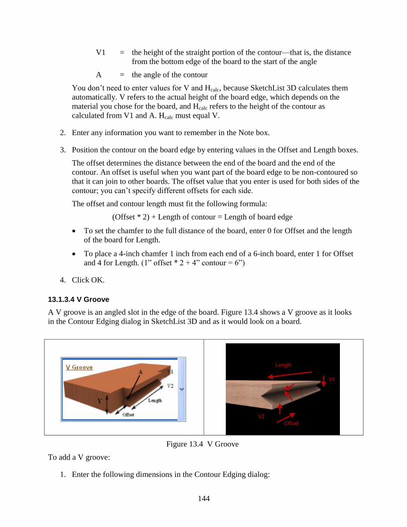
144
V1 = the height of the straight portion of the contour—that is, the distance
from the bottom edge of the board to the start of the angle
A = the angle of the contour
You don‘t need to enter values for V and Hcalc, because SketchList 3D calculates them
automatically. V refers to the actual height of the board edge, which depends on the
material you chose for the board, and Hcalc refers to the height of the contour as
calculated from V1 and A. Hcalc must equal V.
2. Enter any information you want to remember in the Note box.
3. Position the contour on the board edge by entering values in the Offset and Length boxes.
The offset determines the distance between the end of the board and the end of the
contour. An offset is useful when you want part of the board edge to be non-contoured so
that it can join to other boards. The offset value that you enter is used for both sides of the
contour; you can‘t specify different offsets for each side.
The offset and contour length must fit the following formula:
(Offset * 2) + Length of contour = Length of board edge
To set the chamfer to the full distance of the board, enter 0 for Offset and the length
of the board for Length.
To place a 4-inch chamfer 1 inch from each end of a 6-inch board, enter 1 for Offset
and 4 for Length. (1‖ offset * 2 + 4‖ contour = 6‖)
4. Click OK.
13.1.3.4 V Groove
A V groove is an angled slot in the edge of the board. Figure 13.4 shows a V groove as it looks
in the Contour Edging dialog in SketchList 3D and as it would look on a board.
Figure 13.4 V Groove
To add a V groove:
1. Enter the following dimensions in the Contour Edging dialog:

145
V1 = the height of the straight portion above the angle—that is, the distance
from the top edge of the board to the start of the angle
A = the angle of the contour
V2 = the height of the straight portion below the angle—that is, the distance
from the bottom edge of the board to the start of the angle
You don‘t need to enter values for V and Hcalc, because SketchList 3D calculates them
automatically. V refers to the actual height of the board edge, which depends on the
material you chose for the board, and Hcalc refers to the height of the contour as
calculated from V1, V2, and A. Hcalc must equal V.
2. Enter any information you want to remember in the Note box.
3. Position the contour on the board edge by entering values in the Offset and Length boxes.
The offset determines the distance between the end of the board and the end of the
contour. An offset is useful when you want part of the board edge to be non-contoured so
that it can join to other boards. The offset value that you enter is used for both sides of the
contour; you can‘t specify different offsets for each side.
The offset and contour length must fit the following formula:
(Offset * 2) + Length of contour = Length of board edge
To set the V groove to the full distance of the board, enter 0 for Offset and the length
of the board for Length.
To place a 4-inch V groove 1 inch from each end of a 6-inch board, enter 1 for Offset
and 4 for Length. (1‖ offset * 2 + 4‖ contour = 6‖)
4. Click OK.
13.1.3.5 Bullnose
Figure 13.5 shows a bullnose as it looks in the Contour Edging dialog in SketchList 3D and as it
would look on a board.
Figure 13.5 Bullnose
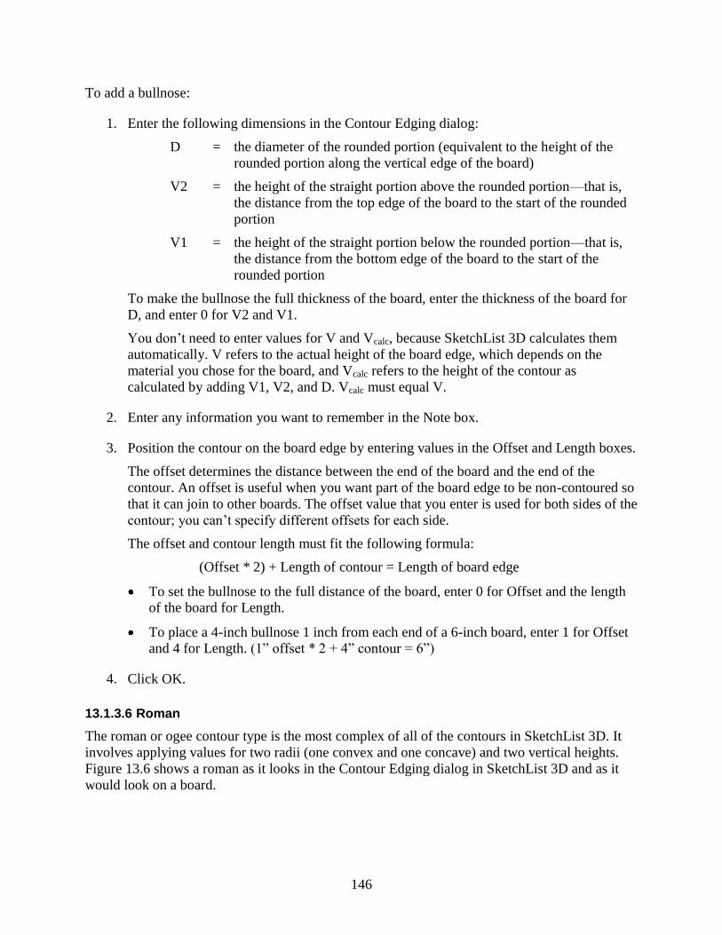
146
To add a bullnose:
1. Enter the following dimensions in the Contour Edging dialog:
D = the diameter of the rounded portion (equivalent to the height of the
rounded portion along the vertical edge of the board)
V2 = the height of the straight portion above the rounded portion—that is,
the distance from the top edge of the board to the start of the rounded
portion
V1 = the height of the straight portion below the rounded portion—that is,
the distance from the bottom edge of the board to the start of the
rounded portion
To make the bullnose the full thickness of the board, enter the thickness of the board for
D, and enter 0 for V2 and V1.
You don‘t need to enter values for V and Vcalc, because SketchList 3D calculates them
automatically. V refers to the actual height of the board edge, which depends on the
material you chose for the board, and Vcalc refers to the height of the contour as
calculated by adding V1, V2, and D. Vcalc must equal V.
2. Enter any information you want to remember in the Note box.
3. Position the contour on the board edge by entering values in the Offset and Length boxes.
The offset determines the distance between the end of the board and the end of the
contour. An offset is useful when you want part of the board edge to be non-contoured so
that it can join to other boards. The offset value that you enter is used for both sides of the
contour; you can‘t specify different offsets for each side.
The offset and contour length must fit the following formula:
(Offset * 2) + Length of contour = Length of board edge
To set the bullnose to the full distance of the board, enter 0 for Offset and the length
of the board for Length.
To place a 4-inch bullnose 1 inch from each end of a 6-inch board, enter 1 for Offset
and 4 for Length. (1‖ offset * 2 + 4‖ contour = 6‖)
4. Click OK.
13.1.3.6 Roman
The roman or ogee contour type is the most complex of all of the contours in SketchList 3D. It
involves applying values for two radii (one convex and one concave) and two vertical heights.
Figure 13.6 shows a roman as it looks in the Contour Edging dialog in SketchList 3D and as it
would look on a board.
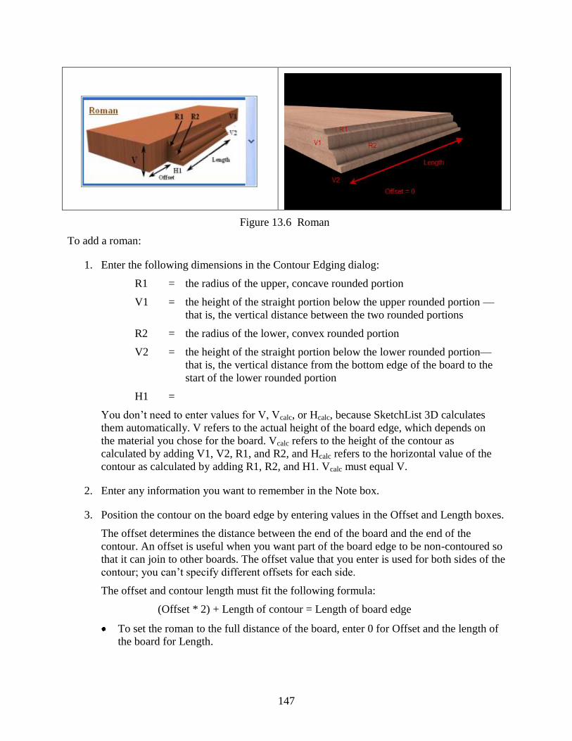
147
Figure 13.6 Roman
To add a roman:
1. Enter the following dimensions in the Contour Edging dialog:
R1 = the radius of the upper, concave rounded portion
V1 = the height of the straight portion below the upper rounded portion —
that is, the vertical distance between the two rounded portions
R2 = the radius of the lower, convex rounded portion
V2 = the height of the straight portion below the lower rounded portion—
that is, the vertical distance from the bottom edge of the board to the
start of the lower rounded portion
H1 =
You don‘t need to enter values for V, Vcalc, or Hcalc, because SketchList 3D calculates
them automatically. V refers to the actual height of the board edge, which depends on
the material you chose for the board. Vcalc refers to the height of the contour as
calculated by adding V1, V2, R1, and R2, and Hcalc refers to the horizontal value of the
contour as calculated by adding R1, R2, and H1. Vcalc must equal V.
2. Enter any information you want to remember in the Note box.
3. Position the contour on the board edge by entering values in the Offset and Length boxes.
The offset determines the distance between the end of the board and the end of the
contour. An offset is useful when you want part of the board edge to be non-contoured so
that it can join to other boards. The offset value that you enter is used for both sides of the
contour; you can‘t specify different offsets for each side.
The offset and contour length must fit the following formula:
(Offset * 2) + Length of contour = Length of board edge
To set the roman to the full distance of the board, enter 0 for Offset and the length of
the board for Length.
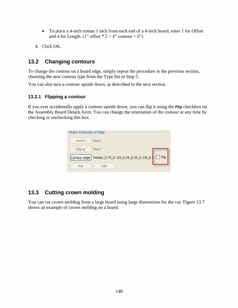
148
To place a 4-inch roman 1 inch from each end of a 6-inch board, enter 1 for Offset
and 4 for Length. (1‖ offset * 2 + 4‖ contour = 6‖)
4. Click OK.
13.2 Changing contours
To change the contour on a board edge, simply repeat the procedure in the previous section,
choosing the new contour type from the Type list in Step 5.
You can also turn a contour upside down, as described in the next section.
13.2.1 Flipping a contour
If you ever accidentally apply a contour upside down, you can flip it using the Flip checkbox on
the Assembly Board Details form. You can change the orientation of the contour at any time by
checking or unchecking this box.
13.3 Cutting crown molding
You can cut crown molding from a large board using large dimensions for the cut. Figure 13.7
shows an example of crown molding on a board.

149
Figure 13.7 Crown molding
For example, you could create a simple cold molding as a crown as follows:
1. Select your material—for example, a 4‖ by 6‖ board.
2. Select one of the edges and add a cove to it.
3. Flip the contour to face the bottom of the board.
4. Cut the board at a 45° degree angle on both ends to allow a mitered connection with
another piece of crown molding.
This approach can be used with any of the contour types in SketchList 3D.
13.4 Placing contours on adjacent boards
Just as you can place different boards with different contours adjacent to each other in the shop,
you can achieve the same designs using contoured edging in SketchList 3-D Professional.
Figure 13.8 shows three boards mounted together. The top and bottom boards have roundover
contours, and the center board has a cove contour cut in it.
Figure 13.8 Contours on adjacent boards

150
13.5 Deleting a contour
To delete a contour, select None from the Type list.

151
14
Working with Shaped Boards
This chapter describes how to create and work with shaped boards. A shaped board is any board
that is neither rectangular or square. This class of boards includes the following:
Boards with rounded edges
Boards with common symmetrical shapes, such as ovals, circles, and triangles
Boards with more unusual symmetrical shapes, such as a boomerang
Boards with non-symmetrical shapes, such as the outline of a tree stump
14.1 Basic concepts
In SketchList 3D, shaping a board involves manipulating points on the edges (perimeter) of the
board, or points related to the edges of the board, to change the board‘s shape. The term
‗manipulating‘ includes moving a point to a new location, adding new points, and deleting
points. You can also change a board into a circle or oval with a single click.
To shape a board, you first open the Shape Toolbar, and then use the tools on the Toolbar to
manipulate the points on the board.

152
Learning to shape a board can take a little practice. If the board gets into a shape you're not
happy with, you can return it to its original shape by clicking Cancel in the Shape Toolbar.
14.2 Opening the Shape Toolbar
To open the Shape Toolbar so you can get started with shaping a board:
1. Open the project that contains the board you want to shape.
2. In the Project Spreadsheet, select the assembly that contains the board.
3. In the Hierarchical Levels area, select Assembly Level.

153
4. Select the board you want to shape.
You can do this in the Views area or the Assembly Spreadsheet.
5. In the Hierarchical Levels area, select Board Details Level.
6. In the Assembly Board Details spreadsheet, select one of the board‘s surfaces.
It doesn‘t matter which surface you choose, as long as you select a surface. If an edge is
selected, the Shape button in the next step will not be active. You may need to scroll
down in the spreadsheet to see the surfaces.
7. In the Assembly Board Details area, click Shape.
You may need to scroll down to see this button.

154
The Shape Toolbar opens on the left side of the SketchList 3D window, and the Views
area changes to a single view of the top of the board.
14.3 Shaping a board
This section starts by explaining how to round the corners of a board and how to create circles
and ovals, and then moves on to more complicated techniques like changing a line to a spline.
You can return a board to its original shape at any time by clicking Cancel.
14.3.1 Rounding the corners of a board
You can use the Point Fillet tool to make one or more corners of the board round. To do this:
1. Click Point Fillet.
2. Click the corner you want to round.
SketchList 3D rounds the corner for you automatically.
14.3.2 Creating a circle or oval
To create a circle or oval:
In the Shape Toolbar, click In-circle or In-oval.
The board becomes a circle or an oval, depending on which button you clicked. You can
change the shape further by selecting a point on the circle or on one of the tangents (the
red lines) and dragging the point to a new location.

155
14.3.3 Selecting and moving a point
To select a point:
1. Click Select.
2. Click a point on the outline of the shape and, without releasing the mouse button, drag the
point to a new location.
If the shape is a circle or ovoid, you can drag a blue point on the edge of the shape to create an
ovoid, such as the one in the following picture. You can also drag the red points on the tangents
to create additional shapes.
14.3.4 Changing a line to a curve
To convert a line to a curve:
1. Click Convert to Curve.
2. Click the line you want to convert.
Two red points appear near the center of the line.
The red points

156
3. To create the curve, move each of the red points to a new location.
You can move the points one by one. When you move a red point, you're not moving the
line itself to create the curve; instead, you're moving a point on a line that is tangent to
the curve you are creating.
14.3.5 Changing a line to a spline
Changing a line to a spline is similar to changing a line to a curve. However, when you change
to a spline, SketchList 3D inserts additional points that you can manipulate.
To change a line to a spline:
1. Click Convert to Spline.
2. Click the line you want to convert.
A blue point appears where you clicked, and two red points appear on each side of the
blue point. If you need to click exactly in the middle of a line, you can use the
information in the positioning dialog to help you find the middle.
Points on the line
The positioning
dialog

157
3. Manipulate the new points—and any of the other points on the edge of the board—to
create the curve you want.
The blue point is on the edge of the board, and the red points indicate tangents.
14.3.6 Changing a curve to a line
To convert a curve to a line:
1. Click Convert to Line.
2. Click the curve you want to convert.
If there are points on the curve, you may want to click to the side of the point where you
want the line to start.
Fig. 14.1 A circle with one of its quarter-arcs converted to a line
14.3.7 Inserting a point
The more points your shape has, the more flexibility you have in working with it. For example,
if you have four points—one at each corner of the board—you can manipulate the corners, but
not the edges of the board. However, if you insert a point along an edge, you can move that
point in the same way you move other points. In the following diagram, a point has been
inserted in the middle of the back edge and then moved in toward the center of the board.

158
To insert a point:
1. Click Insert Point.
2. Click the spot at which you want to insert a point.
If you want to place the point exactly in the middle of a line, you can use the information
in the positioning dialog to help you find the middle.
14.3.8 Deleting a point
At times, you may find it useful to delete a point—for example, if you want to turn a square
board into a triangle. When you delete a point on a corner, the two edges that join at that corner
become a single edge—so, for example, if you delete the upper right corner of a square or
rectangular board, you are left with a triangle that has a right angle in the lower left corner. The
following diagrams illustrate this.
14.2 Starting point: A rectangular board
14.3 Formerly rectangular board with the upper left right deleted

159
To delete a point:
1. Click Delete.
2. Click the point you want to delete.
14.4 Working with the grid
You can hide the grid lines by clicking the Hide button.
You can also make sure that when you move a point, its new position is aligned with an
intersection on the grid. To do this, check the Snap to Grid box.


![Utility V6.0.1 user manual v2.ppt [相容模式]Utility V6.0.1 & Touch screen Panel User Manual Mar. 2019 v2. Strictly Confidential Printing work flow 2 1. Get 3D file (*.stl) from](https://img.pdfslide.us/doc/110x75/5e4fe86db70e426ee114d1fd/utility-v601-user-manual-v2ppt-c-utility-v601-touch-screen.jpg)