Embed Size (px)
Citation preview
FACULDADE DE ENGENHARIA DA UNIVERSIDADE DO PORTO
Sketch-based Facial Modeling andAnimation: an approach based on
mobile devices
Ana Luísa de Vila Fernandes Orvalho
PREPARATION OF THE MSC DISSERTATION
PREPARATION OF THE MSC DISSERTATION
Supervisor: Prof. Augusto Sousa (FEUP)
Co-supervisor: Prof. Verónica Orvalho (FCUP)
February 13, 2013

c© Ana Orvalho, 2013
Contents
1 Introduction 11.1 Motivation . . . . . . . . . . . . . . . . . . . . . . . . . . . . . . . . . . . . . . 1
1.1.1 The LIFEisGAME Project . . . . . . . . . . . . . . . . . . . . . . . . . 21.2 Objectives and Contributions . . . . . . . . . . . . . . . . . . . . . . . . . . . . 31.3 Outline . . . . . . . . . . . . . . . . . . . . . . . . . . . . . . . . . . . . . . . 3
2 Character Facial Animation 52.1 Facial Animation . . . . . . . . . . . . . . . . . . . . . . . . . . . . . . . . . . 5
2.1.1 Facial Animation Pipeline . . . . . . . . . . . . . . . . . . . . . . . . . 62.1.2 Facial Rigging . . . . . . . . . . . . . . . . . . . . . . . . . . . . . . . 7
2.1.2.1 Blend Shapes . . . . . . . . . . . . . . . . . . . . . . . . . . 82.1.2.2 Bones . . . . . . . . . . . . . . . . . . . . . . . . . . . . . . 92.1.2.3 Combined techniques . . . . . . . . . . . . . . . . . . . . . . 92.1.2.4 Geometrically-based . . . . . . . . . . . . . . . . . . . . . . . 102.1.2.5 Physically-based . . . . . . . . . . . . . . . . . . . . . . . . . 102.1.2.6 Rig Control Interface . . . . . . . . . . . . . . . . . . . . . . 11
2.1.3 Animation Techniques . . . . . . . . . . . . . . . . . . . . . . . . . . . 122.1.3.1 Keyframe Animation . . . . . . . . . . . . . . . . . . . . . . 122.1.3.2 Motion Capture Animation . . . . . . . . . . . . . . . . . . . 132.1.3.3 Procedural Animation . . . . . . . . . . . . . . . . . . . . . . 13
2.1.4 Facial Standardization . . . . . . . . . . . . . . . . . . . . . . . . . . . 142.1.4.1 FACS - Facial Action Coding System . . . . . . . . . . . . . . 142.1.4.2 MPEG-4 Facial Animation . . . . . . . . . . . . . . . . . . . 15
3 Sketching Interaction 173.1 Interactive Devices . . . . . . . . . . . . . . . . . . . . . . . . . . . . . . . . . 17
3.1.1 Natural User Interfaces . . . . . . . . . . . . . . . . . . . . . . . . . . . 183.1.2 Multi-touch interfaces . . . . . . . . . . . . . . . . . . . . . . . . . . . 19
3.1.2.1 Multi-touch Tables . . . . . . . . . . . . . . . . . . . . . . . . 193.1.2.2 Tablets . . . . . . . . . . . . . . . . . . . . . . . . . . . . . . 20
3.1.3 Spatial Interaction . . . . . . . . . . . . . . . . . . . . . . . . . . . . . 223.2 Sketch-based Interfaces Pipeline . . . . . . . . . . . . . . . . . . . . . . . . . . 23
3.2.1 Sketch Acquisition . . . . . . . . . . . . . . . . . . . . . . . . . . . . . 243.2.2 Sketch Filtering . . . . . . . . . . . . . . . . . . . . . . . . . . . . . . . 243.2.3 Sketch Interpretation . . . . . . . . . . . . . . . . . . . . . . . . . . . . 25
3.2.3.1 Gesture-based Recognition . . . . . . . . . . . . . . . . . . . 253.2.3.2 Geometric-based Recognition . . . . . . . . . . . . . . . . . . 26
i

ii CONTENTS
4 Natural Sketching for Facial Animation 294.1 Challenges . . . . . . . . . . . . . . . . . . . . . . . . . . . . . . . . . . . . . . 294.2 System Description . . . . . . . . . . . . . . . . . . . . . . . . . . . . . . . . . 30
4.2.1 Mode A: Standalone version . . . . . . . . . . . . . . . . . . . . . . . . 304.2.2 Mode B: Collaborative environment . . . . . . . . . . . . . . . . . . . . 30
4.3 Tools . . . . . . . . . . . . . . . . . . . . . . . . . . . . . . . . . . . . . . . . . 314.3.1 Unity . . . . . . . . . . . . . . . . . . . . . . . . . . . . . . . . . . . . 31
4.4 Work Plan . . . . . . . . . . . . . . . . . . . . . . . . . . . . . . . . . . . . . . 31
5 Conclusion 35
References 37
List of Figures
2.1 The Uncanny Valley (Original graph by Dr. Masahiro Mori, 1982). The originalhypothesis stated that as the appearance of an entity becomes more human-like,a human observer’s emotional response becomes increasingly positive and em-pathic, until a certain point beyond which it becomes repulsing. . . . . . . . . . . 6
2.2 Different stages of a traditional animation pipeline . . . . . . . . . . . . . . . . . 72.3 Blendshapes of four basic expressions: happy, sad, surprise and angry (Copyright
2004 New Riders Publishing). . . . . . . . . . . . . . . . . . . . . . . . . . . . 82.4 A bone-driven rig based on a highly articulated facial skeleton structure (Copyright
2001-2007 Epic Games). . . . . . . . . . . . . . . . . . . . . . . . . . . . . . . 92.5 Free-Form Deformation applied to a spheric surface: controlling box and embed-
ded object; left: neutral position; right: object deformation [1]. . . . . . . . . . . 102.6 Two window-based UI. Left: slider-based UI based on FACS [2]; Right: interface
with multiple columns of attributes [3] . . . . . . . . . . . . . . . . . . . . . . 112.7 Three examples of viewport-based UI. a) 2D controls by Alexander et al. [4]; b)
3D controls by Komorowski et al. [5]; c) 3D controls by Grubb [6] . . . . . . . 122.8 Two different poses and the resulting interpolation. Left: Neutral pose, Right: ”A”
mouth shape, Middle: Interpolated shape. [1] . . . . . . . . . . . . . . . . . . . 122.9 FACS. Upper row: Sample single facial AUs; Lower row: Sets of AUs for basic
expressions [1] . . . . . . . . . . . . . . . . . . . . . . . . . . . . . . . . . . . 152.10 MPEG-4 Facial Animation. Left: Some Feature Points (FP); Right: A face model
in its neutral state and the FPs used to define FAPUs. Fractions of distances be-tween the marked FPs are used to define FAPU [7]. . . . . . . . . . . . . . . . . 16
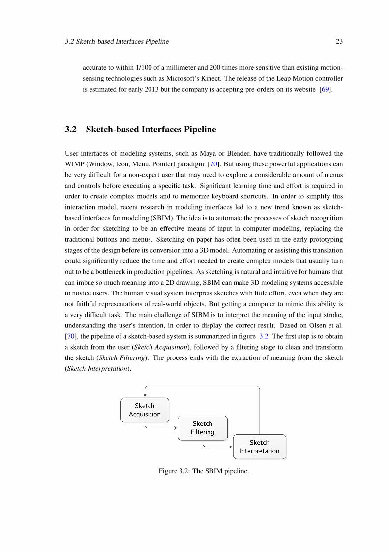
3.1 The evolution of interfaces. . . . . . . . . . . . . . . . . . . . . . . . . . . . . . 183.2 The SBIM pipeline. . . . . . . . . . . . . . . . . . . . . . . . . . . . . . . . . . 233.3 The input stroke (left) is acquired as a sequence of point samples spaced irregularly
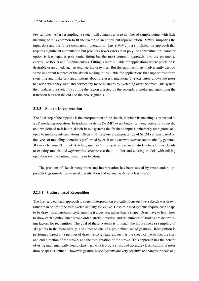
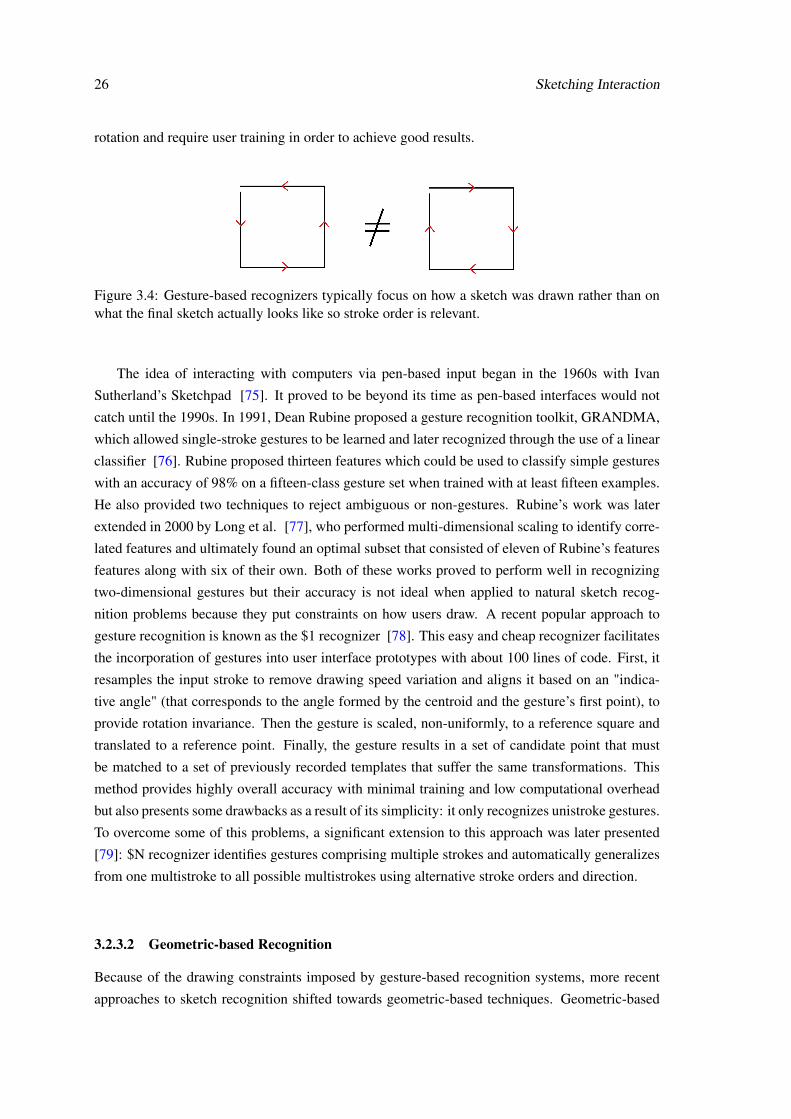
according to drawing speed(right). . . . . . . . . . . . . . . . . . . . . . . . . . 243.4 Gesture-based recognizers typically focus on how a sketch was drawn rather than
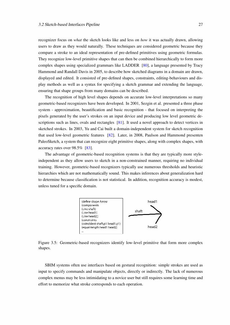
on what the final sketch actually looks like so stroke order is relevant. . . . . . . 263.5 Geometric-based recognizers identify low-level primitive that form more complex
shapes. . . . . . . . . . . . . . . . . . . . . . . . . . . . . . . . . . . . . . . . . 27
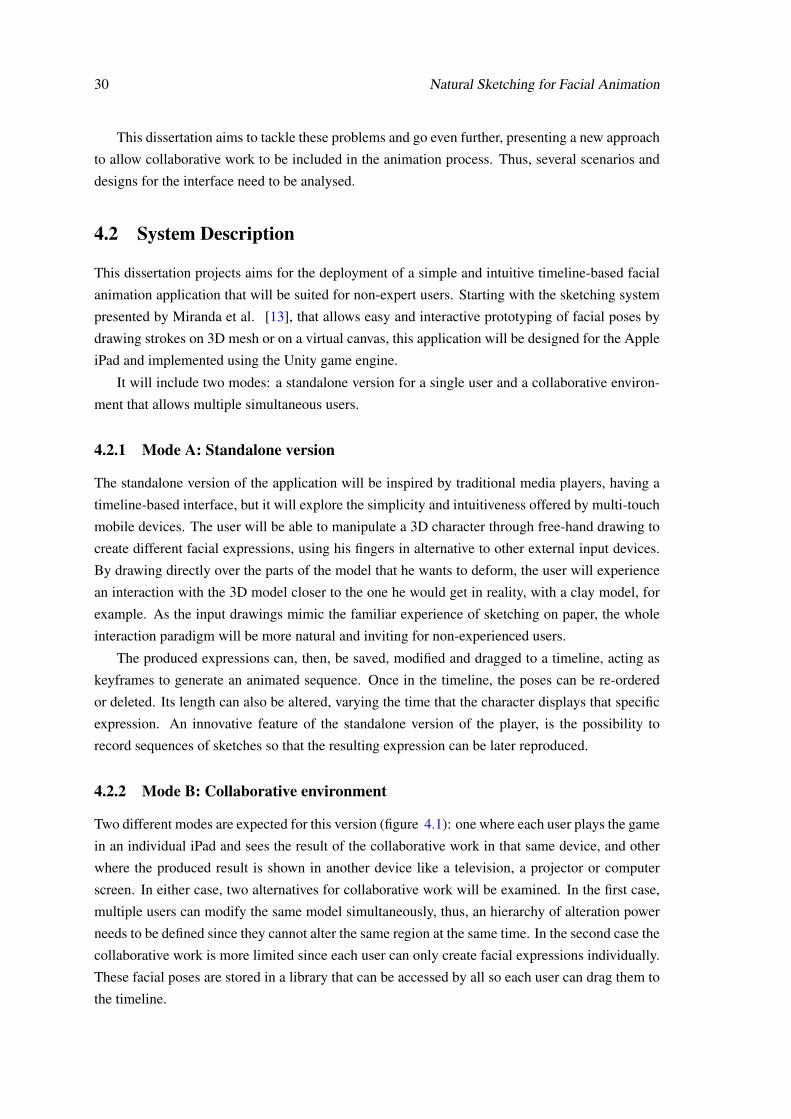
4.1 Two possible modes foreseen for the collaborative version of the application: (a)individual actions and the result of the collaborative work are displayed in eachdevice; (b) the results are displayed in an external device . . . . . . . . . . . . . 31
4.2 Work plan . . . . . . . . . . . . . . . . . . . . . . . . . . . . . . . . . . . . . . 33
iii

iv LIST OF FIGURES
Abbreviations
2D 2 Dimensions3D 3 DimensionsAPI Application Programming InterfaceASD Autism Spectrum DisorderAU Action UnitAVO Audiovisual ObjectCAD Computer-Aided DesignCG Computer GraphicsCLI Command-Line InterfaceFACS Facial Action Coding SystemFAP Facial Animation ParametersFAPU Facial Animation Parameter UnitFFD Free-Form DeformerFP Feature PointGUI Graphical User InterfaceHCI Human-Computer InteractionHD High-DefinitionIEC International Electrotechnical CommissionISO International Organization for StandardizationLED Light-Emitting DiodeLCD Liquid Crystal DisplayLIFEisGAME LearnIng of Facial Emotions usIng Serious GAMEsMPEG Moving Picture Experts GroupMoCap Motion CaptureNUI Natural User InterfaceNURBS Non Uniform Rational B-SplineOEM Original Equipment ManufacturerPC Personal Computerppi Pixels per inchRFFD Rational Free-Form DeformerRGB Red–Green–BlueSBIM Sketch Based Interfaces for ModelingSDK Software Development KitTV TelevisionUbiComp Ubiquitous ComputingUI User InterfaceWIMP Window, Icon, Menu, Pointer
v

Chapter 1
Introduction
Freehand sketching has always been a crucial part of everyday human interaction. It has been used
throughout time to communicate ideas to others and to help the thinking process, clarifying one’s
thoughts. As it is a natural and intuitive means of communication, sketching is a promising tool
to ease the human-computer interaction paradigm. This is particularly interesting for the field of
facial animation, once it can help non-expert users to easily model and animate characters. Sim-
ple free-hand strokes can replace traditional buttons, sliders and keyboard shortcuts as a means of
input to control modeling and animation applications.
This document presents the dissertation proposal whose overall goal is to deploy a timeline-
based facial animation player for mobile devices (e.g. tablets). The system will be developed for
the iPad and implemented using the Unity engine. The player will consist of a 2D interface that
allows the user to create facial expressions on-the-fly by drawing strokes on a 3D model. The
user will be able to create, edit, control and animate facial models. The application will have two
modes: (i) a standalone facial player that will run on one iPad, (ii) a collaborative environment
where users can simultaneously alter the same model or share created poses to generate animated
sequences.
This chapter provides a brief background of the project LIFEisGAME, describes the moti-
vation, main challenges, objectives and proposed solution of this dissertation and presents the
foreseen schedule of the project.
1.1 Motivation
Interactive devices with pen-based interfaces have become popular in recent years and tablets
and touch screens are now common modes of input for many applications [8]. Sketching, as
an intuitive means of communication, provides a natural alternative to the multi-tool selection
paradigm of traditional interfaces, being now used in a variety of domains such as front ends for
Computer-Aided Design (CAD) systems, automatic correction or understanding of diagrams for
immediate feedback in educational settings, alternative inputs for small keyboard-less devices, or
1
2 Introduction
gestural interfaces. In the context of facial animation, a sketch-based interface can significantly
ease the manipulation of the virtual characters, opening new opportunities for non-expert users that
usually take a lot of time to master the powerful but complex interfaces of traditional modeling
and animation applications.
This dissertation is inspired by the LIFEisGAME project that intends to help children with
Autism Spectrum Disorder (ASD) to recognize facial emotions in an interactive and creative way.
ASDs are a group of development disabilities whose symptoms include problems with social in-
teraction, communication (verbal and/or non-verbal), restricted activities and interests, both in
children and adults. The severity of the symptoms, their combinations and patterns of behaviour
significantly varies from patient to patient.
1.1.1 The LIFEisGAME Project
LIFEisGAME (LearnIng of Facial Emotions usIng Serious GAMEs) [9] is a project funded by
Fundação para a Ciência e a Tecnologia (FCT) [10] under the program UT Austin|Portugal, also
known as the International Collaboratory for Emerging Technologies (CoLab) [11], in partner-
ship with Faculdade de Psicologia e Ciências da Educação da Universidade do Porto, University
of Texas in Austin, Instituto de Telecomunicações [12] and Microsoft. It explores a new and in-
novative approach that uses a serious game to teach children with ASDs to recognize and express
facial emotions. The main objective of the LIFEisGAME project is to deploy a low cost real time
facial animation system embedded in an experimental game that enables further study of the facial
emotion recognition challenges of these children and also allows to analyse if the use of virtual
characters in interactive training programs can help the rehabilitation of ASDs patients. The game
is intended to include 4 modules: Become Your Avatar, where the player recalls to own facial ex-
pressions to learn about emotions; Build a Face, where the player draws facial expressions on an
avatar and learns about facial clues; What a Feeling, that allows exploration of facial expressions
through comparison tasks and Live the Story, where the user learns about how different actions
can lead to different emotions through the interaction between avatars.
The work of this dissertation will focus on the Build a Face module that uses sketch-recognition
techniques to allow the player to draw facial expressions on an avatar, modifying its appearance,
using an interactive device. The core of this module is already deployed [13] and consists in a
sketching system that allows easy and interactive prototyping of facial poses by drawing strokes on
3D mesh or on a virtual canvas. The goal of this dissertation is to create a facial animation player
for the iPad, based on this sketching method, extending the scope of the LIFEisGAME project to
individuals without ASDs.
1.2 Objectives and Contributions 3
1.2 Objectives and Contributions
The following objectives are expected to be accomplished at the end of this dissertation:
O1. To carry out research on facial animation techniques with special focus on sketch-based
animation interfaces that leads to a timeline-based facial animation application with high quality,
based on the facial sketching control method developed by Miranda et al. [13].
O2. To carry out research on interactive devices technology and the new trends in user inter-
faces so that the final application suits the chosen implementation platform: the iPad.
O3. To explore different models to define the most adequate user interface to allow an easy
and intuitive manipulation and animation of 3D characters.
O4. To deploy a functional prototype application of the standalone version of the player for
the iPad.
O5. To provide a methodology and propose an interface design to expand the application to a
collaborative environment, allowing simultaneous alteration of a single model and joint effort in
the animation process.
These objectives will lead to the following contributions:
C1. Deployment a simple and intuitive application to animate 3D facial models for the iPad
that will expand the scope of the LIFEisGAME project also to individuals without ASD.
C2. Study and design of a collaborative environment that will increase the immersiveness
of the animation application. This increases the challenge and the entertainment of animating
several poses of a 3D model and, under a psychotherapy point of view, can help to improve the
communication skills of autistic children while learning to recognize facial expressions.
1.3 Outline
The remaining chapters of this thesis proposal are organized as follows:
Chapter 2: Character Facial Animation Discusses the complexity of facial animation,
briefly describes the stages of a traditional animation pipeline and the major techniques used in
each one.

4 Introduction
Chapter 3: Sketching Interaction Presents an evolution of user interfaces and a study of
emergent technologies related to interactive devices. It also details a new approach in the human-
computer interaction model - sketch-based interfaces - and how it can be used to ease the modeling
and animation processes.
Chapter 4: Natural Sketching for Facial Animation Describes the main goal of this dis-
sertation and how it relates with the previously reviewed state of the art. It presents the main
challenges raised by the deployment of a facial animation player for mobile devices, details the
proposed solution and schedules the future work.
Chapter 5: Conclusion Presents a brief summary of the document and the final considerations
about the project.
Chapter 2
Character Facial Animation
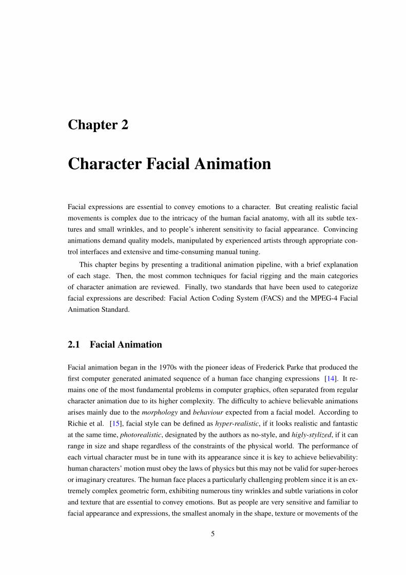
Facial expressions are essential to convey emotions to a character. But creating realistic facial
movements is complex due to the intricacy of the human facial anatomy, with all its subtle tex-
tures and small wrinkles, and to people’s inherent sensitivity to facial appearance. Convincing
animations demand quality models, manipulated by experienced artists through appropriate con-
trol interfaces and extensive and time-consuming manual tuning.
This chapter begins by presenting a traditional animation pipeline, with a brief explanation
of each stage. Then, the most common techniques for facial rigging and the main categories
of character animation are reviewed. Finally, two standards that have been used to categorize
facial expressions are described: Facial Action Coding System (FACS) and the MPEG-4 Facial
Animation Standard.
2.1 Facial Animation
Facial animation began in the 1970s with the pioneer ideas of Frederick Parke that produced the
first computer generated animated sequence of a human face changing expressions [14]. It re-
mains one of the most fundamental problems in computer graphics, often separated from regular
character animation due to its higher complexity. The difficulty to achieve believable animations
arises mainly due to the morphology and behaviour expected from a facial model. According to
Richie et al. [15], facial style can be defined as hyper-realistic, if it looks realistic and fantastic
at the same time, photorealistic, designated by the authors as no-style, and higly-stylized, if it can
range in size and shape regardless of the constraints of the physical world. The performance of
each virtual character must be in tune with its appearance since it is key to achieve believability:
human characters’ motion must obey the laws of physics but this may not be valid for super-heroes
or imaginary creatures. The human face places a particularly challenging problem since it is an ex-
tremely complex geometric form, exhibiting numerous tiny wrinkles and subtle variations in color
and texture that are essential to convey emotions. But as people are very sensitive and familiar to
facial appearance and expressions, the smallest anomaly in the shape, texture or movements of the
5
6 Character Facial Animation
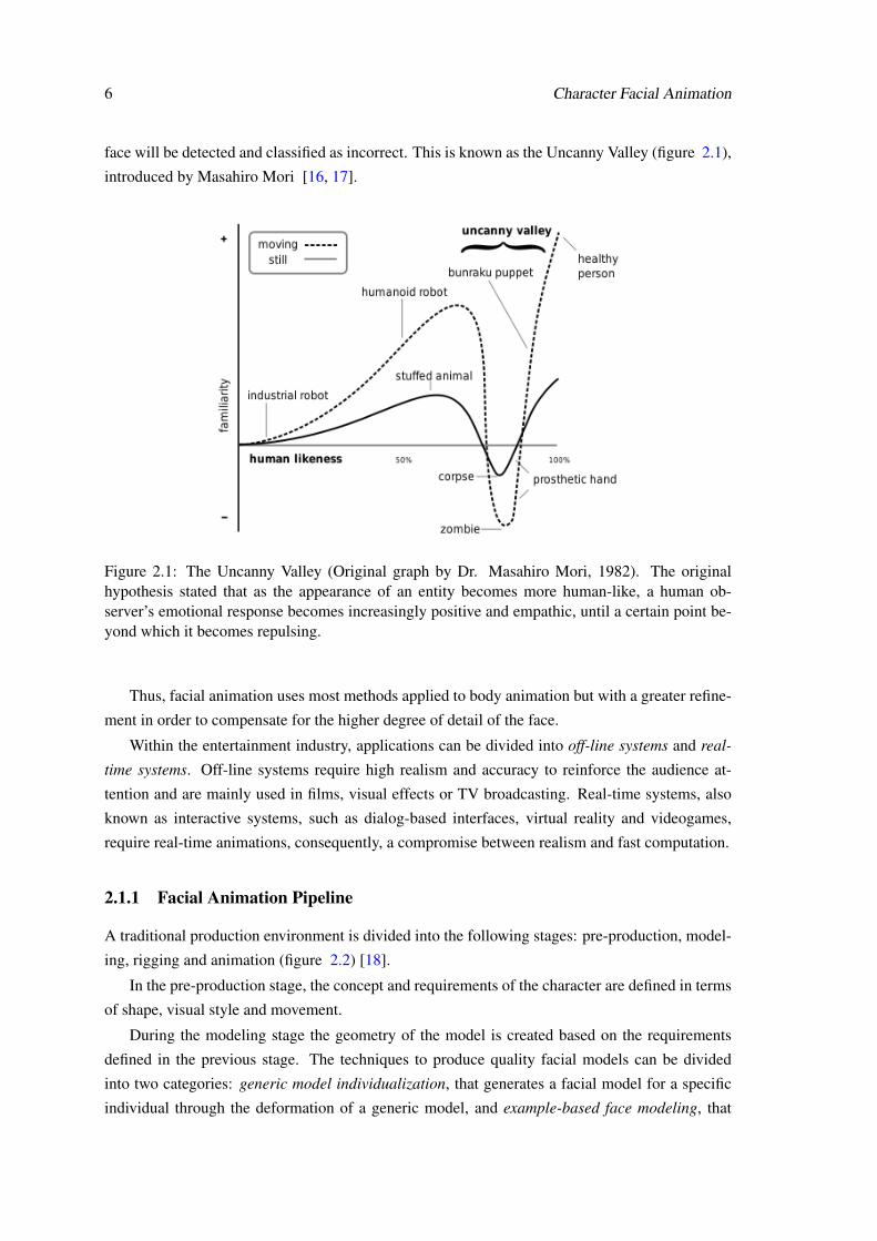
face will be detected and classified as incorrect. This is known as the Uncanny Valley (figure 2.1),
introduced by Masahiro Mori [16, 17].
Figure 2.1: The Uncanny Valley (Original graph by Dr. Masahiro Mori, 1982). The originalhypothesis stated that as the appearance of an entity becomes more human-like, a human ob-server’s emotional response becomes increasingly positive and empathic, until a certain point be-yond which it becomes repulsing.
Thus, facial animation uses most methods applied to body animation but with a greater refine-
ment in order to compensate for the higher degree of detail of the face.
Within the entertainment industry, applications can be divided into off-line systems and real-
time systems. Off-line systems require high realism and accuracy to reinforce the audience at-
tention and are mainly used in films, visual effects or TV broadcasting. Real-time systems, also
known as interactive systems, such as dialog-based interfaces, virtual reality and videogames,
require real-time animations, consequently, a compromise between realism and fast computation.
2.1.1 Facial Animation Pipeline
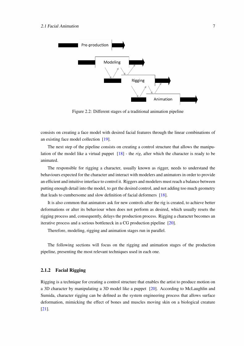
A traditional production environment is divided into the following stages: pre-production, model-
ing, rigging and animation (figure 2.2) [18].
In the pre-production stage, the concept and requirements of the character are defined in terms
of shape, visual style and movement.
During the modeling stage the geometry of the model is created based on the requirements
defined in the previous stage. The techniques to produce quality facial models can be divided
into two categories: generic model individualization, that generates a facial model for a specific
individual through the deformation of a generic model, and example-based face modeling, that
2.1 Facial Animation 7
Figure 2.2: Different stages of a traditional animation pipeline
consists on creating a face model with desired facial features through the linear combinations of
an existing face model collection [19].
The next step of the pipeline consists on creating a control structure that allows the manipu-
lation of the model like a virtual puppet [18] - the rig, after which the character is ready to be
animated.
The responsible for rigging a character, usually known as rigger, needs to understand the
behaviours expected for the character and interact with modelers and animators in order to provide
an efficient and intuitive interface to control it. Riggers and modelers must reach a balance between
putting enough detail into the model, to get the desired control, and not adding too much geometry
that leads to cumbersome and slow definition of facial deformers [18].
It is also common that animators ask for new controls after the rig is created, to achieve better
deformations or alter its behaviour when does not perform as desired, which usually resets the
rigging process and, consequently, delays the production process. Rigging a character becomes an
iterative process and a serious bottleneck in a CG production pipeline [20].
Therefore, modeling, rigging and animation stages run in parallel.
The following sections will focus on the rigging and animation stages of the production
pipeline, presenting the most relevant techniques used in each one.
2.1.2 Facial Rigging
Rigging is a technique for creating a control structure that enables the artist to produce motion on
a 3D character by manipulating a 3D model like a puppet [20]. According to McLaughlin and
Sumida, character rigging can be defined as the system engineering process that allows surface
deformation, mimicking the effect of bones and muscles moving skin on a biological creature
[21].
8 Character Facial Animation
Every rig must provide easy animation controls that work as expected and should allow small
modifications to correct undesired behaviours. In order to avoid strange or impossible moves that
do not follow the requirements predefined for a specific character, the rig should include a set of
constraints [22].
The rig control points can be attached to selected areas of the model and affect the corre-
spondent area accordingly to the geometric operation (translation, rotation and scaling) applied
to them. The rig determines the quality and the number of potential animations. More control
points allow smoother animations but also lead to a system that is more complex to animate and
maintain. As face animation must preserve the subtleties of facial expressions, a high number of
joints is required to achieve realistic results.
The most common approaches to create a facial rig are based on blend shapes, bones-driven
techniques or a combination of both. To complement these approaches, an additional layer of de-
formation can be added to a model in areas where neither bones nor shapes successfully reproduce
facial features such as wrinkles. These deformers can be divided in two groups: geometrically-
based and physically-based methods.
2.1.2.1 Blend Shapes
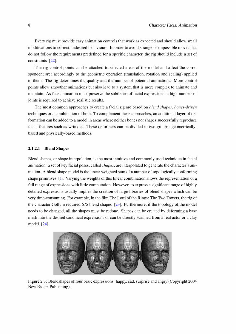
Blend shapes, or shape interpolation, is the most intuitive and commonly used technique in facial
animation: a set of key facial poses, called shapes, are interpolated to generate the character’s ani-
mation. A blend shape model is the linear weighted sum of a number of topologically conforming
shape primitives [1]. Varying the weights of this linear combination allows the representation of a
full range of expressions with little computation. However, to express a significant range of highly
detailed expressions usually implies the creation of large libraries of blend shapes which can be
very time-consuming. For example, in the film The Lord of the Rings: The Two Towers, the rig of
the character Gollum required 675 blend shapes [23]. Furthermore, if the topology of the model
needs to be changed, all the shapes must be redone. Shapes can be created by deforming a base
mesh into the desired canonical expressions or can be directly scanned from a real actor or a clay
model [24].
Figure 2.3: Blendshapes of four basic expressions: happy, sad, surprise and angry (Copyright 2004New Riders Publishing).
2.1 Facial Animation 9
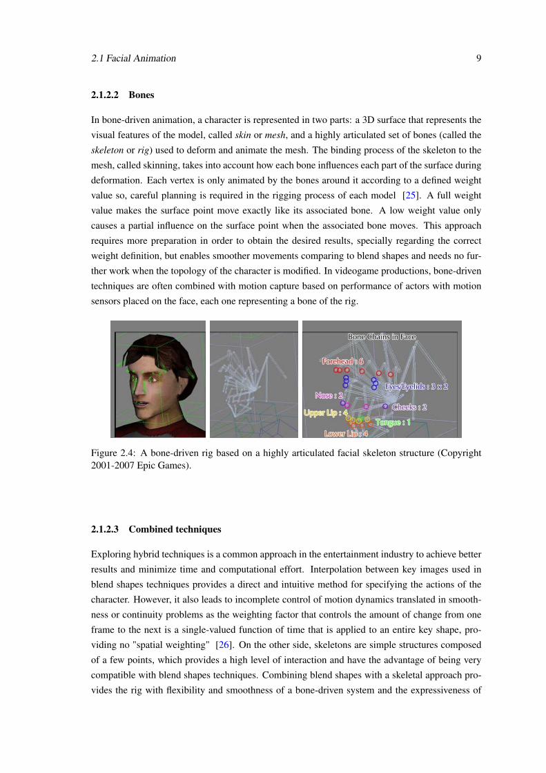
2.1.2.2 Bones
In bone-driven animation, a character is represented in two parts: a 3D surface that represents the
visual features of the model, called skin or mesh, and a highly articulated set of bones (called the
skeleton or rig) used to deform and animate the mesh. The binding process of the skeleton to the
mesh, called skinning, takes into account how each bone influences each part of the surface during
deformation. Each vertex is only animated by the bones around it according to a defined weight
value so, careful planning is required in the rigging process of each model [25]. A full weight
value makes the surface point move exactly like its associated bone. A low weight value only
causes a partial influence on the surface point when the associated bone moves. This approach
requires more preparation in order to obtain the desired results, specially regarding the correct
weight definition, but enables smoother movements comparing to blend shapes and needs no fur-
ther work when the topology of the character is modified. In videogame productions, bone-driven
techniques are often combined with motion capture based on performance of actors with motion
sensors placed on the face, each one representing a bone of the rig.
Figure 2.4: A bone-driven rig based on a highly articulated facial skeleton structure (Copyright2001-2007 Epic Games).
2.1.2.3 Combined techniques
Exploring hybrid techniques is a common approach in the entertainment industry to achieve better
results and minimize time and computational effort. Interpolation between key images used in
blend shapes techniques provides a direct and intuitive method for specifying the actions of the
character. However, it also leads to incomplete control of motion dynamics translated in smooth-
ness or continuity problems as the weighting factor that controls the amount of change from one
frame to the next is a single-valued function of time that is applied to an entire key shape, pro-
viding no "spatial weighting" [26]. On the other side, skeletons are simple structures composed
of a few points, which provides a high level of interaction and have the advantage of being very
compatible with blend shapes techniques. Combining blend shapes with a skeletal approach pro-
vides the rig with flexibility and smoothness of a bone-driven system and the expressiveness of
10 Character Facial Animation
blend shapes [27]. Moreover, skeleton control can be applied selectively to parts of the model
that require enhancement.
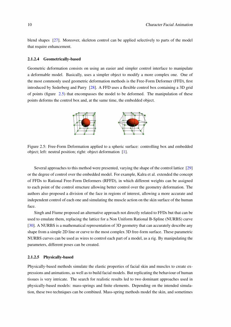
2.1.2.4 Geometrically-based
Geometric deformation consists on using an easier and simpler control interface to manipulate
a deformable model. Basically, uses a simpler object to modify a more complex one. One of
the most commonly used geometric deformation methods is the Free-Form Deformer (FFD), first
introduced by Sederberg and Parry [28]. A FFD uses a flexible control box containing a 3D grid
of points (figure 2.5) that encompasses the model to be deformed. The manipulation of these
points deforms the control box and, at the same time, the embedded object.
Figure 2.5: Free-Form Deformation applied to a spheric surface: controlling box and embeddedobject; left: neutral position; right: object deformation [1].
Several approaches to this method were presented, varying the shape of the control lattice [29]
or the degree of control over the embedded model. For example, Kalra et al. extended the concept
of FFDs to Rational Free-Form Deformers (RFFD), in which different weights can be assigned
to each point of the control structure allowing better control over the geometry deformation. The
authors also proposed a division of the face in regions of interest, allowing a more accurate and
independent control of each one and simulating the muscle action on the skin surface of the human
face.
Singh and Fiume proposed an alternative approach not directly related to FFDs but that can be
used to emulate them, replacing the lattice for a Non Uniform Rational B-Spline (NURBS) curve
[30]. A NURBS is a mathematical representation of 3D geometry that can accurately describe any
shape from a simple 2D line or curve to the most complex 3D free-form surface. These parametric
NURBS curves can be used as wires to control each part of a model, as a rig. By manipulating the
parameters, different poses can be created.
2.1.2.5 Physically-based
Physically-based methods simulate the elastic properties of facial skin and muscles to create ex-
pressions and animations, as well as to build facial models. But replicating the behaviour of human
tissues is very intricate. The search for realistic results led to two dominant approaches used in
physically-based models: mass-springs and finite elements. Depending on the intended simula-
tion, these two techniques can be combined. Mass-spring methods model the skin, and sometimes
2.1 Facial Animation 11
muscle and bones, as a number of point masses connected by springs in a lattice structure, like a
cloth. Finite elements methods break the continuous system into a regular discrete representation
with a finite number of elements using, for example, tetrahedrons. This last technique is more
sophisticated, physically accurate and stable than the first, making it more suitable for modelling
continuous materials like soft tissue, but is also computationally far more expensive [31].
Platt and Bladler presented the first physically-based facial animation model that used a mass-
spring system to simulate muscle fibers [32]. Their work used the Facial Action Coding System
(FACS) to determine which muscles to activate in the underlying model (see section 2.1.4.1).
2.1.2.6 Rig Control Interface
The manipulation of the rig deforms the geometry of a 3D character’s model, producing move-
ment. To allow this manipulation, an optional layer of control can be defined - the rig’s user
interface (UI). There are many approaches to handle the UI for rigging but two major categories
can be identified: window-based and viewport-based, which can also be combined.
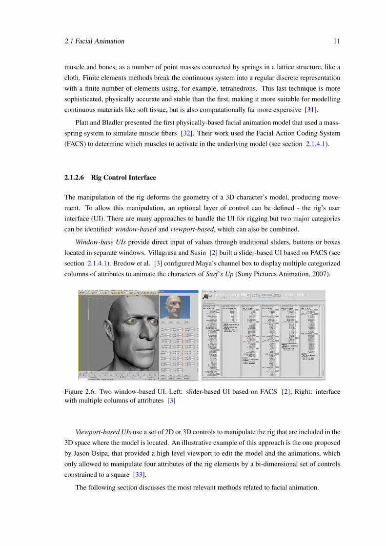
Window-base UIs provide direct input of values through traditional sliders, buttons or boxes
located in separate windows. Villagrasa and Susin [2] built a slider-based UI based on FACS (see
section 2.1.4.1). Bredow et al. [3] configured Maya’s channel box to display multiple categorized
columns of attributes to animate the characters of Surf’s Up (Sony Pictures Animation, 2007).
Figure 2.6: Two window-based UI. Left: slider-based UI based on FACS [2]; Right: interfacewith multiple columns of attributes [3]
Viewport-based UIs use a set of 2D or 3D controls to manipulate the rig that are included in the
3D space where the model is located. An illustrative example of this approach is the one proposed
by Jason Osipa, that provided a high level viewport to edit the model and the animations, which
only allowed to manipulate four attributes of the rig elements by a bi-dimensional set of controls
constrained to a square [33].
The following section discusses the most relevant methods related to facial animation.
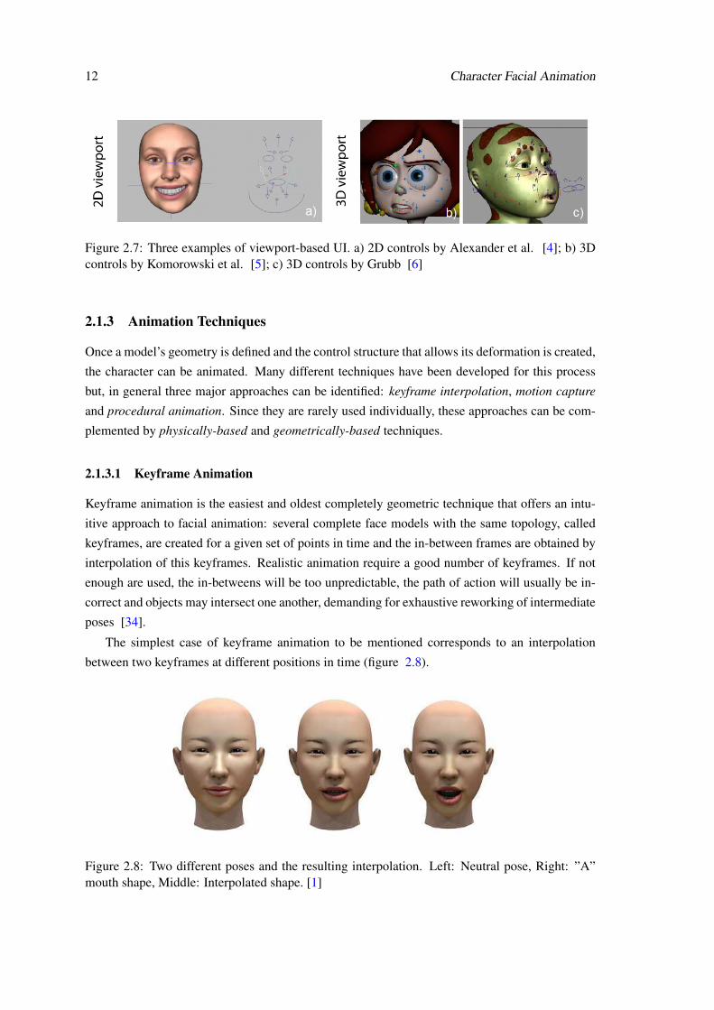
12 Character Facial Animation
Figure 2.7: Three examples of viewport-based UI. a) 2D controls by Alexander et al. [4]; b) 3Dcontrols by Komorowski et al. [5]; c) 3D controls by Grubb [6]
2.1.3 Animation Techniques
Once a model’s geometry is defined and the control structure that allows its deformation is created,
the character can be animated. Many different techniques have been developed for this process
but, in general three major approaches can be identified: keyframe interpolation, motion capture
and procedural animation. Since they are rarely used individually, these approaches can be com-
plemented by physically-based and geometrically-based techniques.
2.1.3.1 Keyframe Animation
Keyframe animation is the easiest and oldest completely geometric technique that offers an intu-
itive approach to facial animation: several complete face models with the same topology, called
keyframes, are created for a given set of points in time and the in-between frames are obtained by
interpolation of this keyframes. Realistic animation require a good number of keyframes. If not
enough are used, the in-betweens will be too unpredictable, the path of action will usually be in-
correct and objects may intersect one another, demanding for exhaustive reworking of intermediate
poses [34].
The simplest case of keyframe animation to be mentioned corresponds to an interpolation
between two keyframes at different positions in time (figure 2.8).
Figure 2.8: Two different poses and the resulting interpolation. Left: Neutral pose, Right: ”A”mouth shape, Middle: Interpolated shape. [1]
2.1 Facial Animation 13
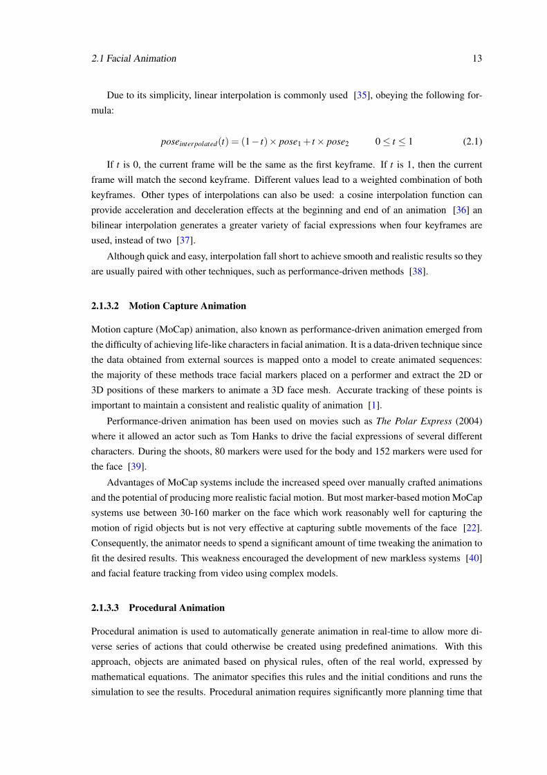
Due to its simplicity, linear interpolation is commonly used [35], obeying the following for-
mula:
poseinterpolated(t) = (1− t)× pose1 + t× pose2 0≤ t ≤ 1 (2.1)
If t is 0, the current frame will be the same as the first keyframe. If t is 1, then the current
frame will match the second keyframe. Different values lead to a weighted combination of both
keyframes. Other types of interpolations can also be used: a cosine interpolation function can
provide acceleration and deceleration effects at the beginning and end of an animation [36] an
bilinear interpolation generates a greater variety of facial expressions when four keyframes are
used, instead of two [37].
Although quick and easy, interpolation fall short to achieve smooth and realistic results so they
are usually paired with other techniques, such as performance-driven methods [38].
2.1.3.2 Motion Capture Animation
Motion capture (MoCap) animation, also known as performance-driven animation emerged from
the difficulty of achieving life-like characters in facial animation. It is a data-driven technique since
the data obtained from external sources is mapped onto a model to create animated sequences:
the majority of these methods trace facial markers placed on a performer and extract the 2D or
3D positions of these markers to animate a 3D face mesh. Accurate tracking of these points is
important to maintain a consistent and realistic quality of animation [1].
Performance-driven animation has been used on movies such as The Polar Express (2004)
where it allowed an actor such as Tom Hanks to drive the facial expressions of several different
characters. During the shoots, 80 markers were used for the body and 152 markers were used for
the face [39].
Advantages of MoCap systems include the increased speed over manually crafted animations
and the potential of producing more realistic facial motion. But most marker-based motion MoCap
systems use between 30-160 marker on the face which work reasonably well for capturing the
motion of rigid objects but is not very effective at capturing subtle movements of the face [22].
Consequently, the animator needs to spend a significant amount of time tweaking the animation to
fit the desired results. This weakness encouraged the development of new markless systems [40]
and facial feature tracking from video using complex models.
2.1.3.3 Procedural Animation
Procedural animation is used to automatically generate animation in real-time to allow more di-
verse series of actions that could otherwise be created using predefined animations. With this
approach, objects are animated based on physical rules, often of the real world, expressed by
mathematical equations. The animator specifies this rules and the initial conditions and runs the
simulation to see the results. Procedural animation requires significantly more planning time that
14 Character Facial Animation
non-procedural approaches but has the advantage of easing the build and tuning stages: by chang-
ing the input parameters it is fast and easy to create new results or to modify previous work.
Several procedural animation systems have been developed to provide a range of useful char-
acter behaviours [41, 42]. Most of them aiming to maximize physical realism in highly dynamic
task such as tumbling. However, in terms of behavioural movements, procedural animation for the
face is a not very explored area.
2.1.4 Facial Standardization
Broadly speaking, within the field of computer facial animation, two kinds of people can be iden-
tified: the researchers and the artists. Researchers are mostly interest in the more technical aspects
of the problems, trying to track facial features in real time in unconstrained video without markers
or studying intricate methods to realistic animate anatomically correct models according to physic
laws. On the other side, artist are concerned with more immediate and practical tasks of produc-
ing high quality facial animations especially for the entertainment industry so they use the best
methods possible provided that they are compatible with the software they already master. Thus,
most of the facial animation methods described in scientific articles never reach the pipelines of
major movies or TV productions. But even within the research community, different groups often
face problems of system interoperability because they do not use the same parameters to detect,
control or animate facial movements [43]. In order to bridge these gaps, significant effort has been
put on describing the face with a small set of control parameters instead of defining its complete
geometry. This parameterization eases the processes of controlling facial movements, acquiring
information from video analysis, reconstructing a head or transferring animations between differ-
ent models.
Research has shown that an ideal parameterization does not exist because it is difficult to
satisfy all user demands for a broad range of facial applications. Parke developed the first facial
parametric model that allowed direct creation of facial deformation by defining ad hoc parameters
or by deriving parameters from the structure and anatomy of the face [37]. Since then, other
approaches for facial standardization have been studied.
The following sections present two standards that have been used to categorize facial expres-
sions.
2.1.4.1 FACS - Facial Action Coding System
The Facial Action Coding System (FACS) is the most widely and versatile method for measuring
and describing facial behaviours, having become a standard to categorize the physical expressions
of emotions. It was originally published by Paul Eckman, Wallace Friesen in 1978 [44] and
updated in 2002, with large contributions from Joseph Hager [45]. They determined how the
contraction of each facial muscle, singly and in combination with other muscles, changes the ap-
pearance of the face by examining videotapes, studying anatomy and palpating their faces. FACS
parameterizes facial expressions in terms of Action Units (AU) that are the fundamental actions of
2.1 Facial Animation 15
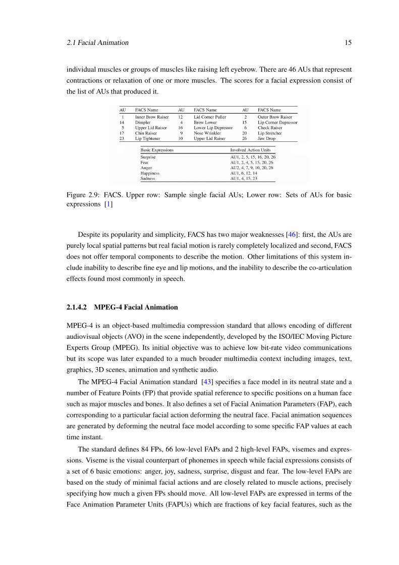
individual muscles or groups of muscles like raising left eyebrow. There are 46 AUs that represent
contractions or relaxation of one or more muscles. The scores for a facial expression consist of
the list of AUs that produced it.
Figure 2.9: FACS. Upper row: Sample single facial AUs; Lower row: Sets of AUs for basicexpressions [1]
Despite its popularity and simplicity, FACS has two major weaknesses [46]: first, the AUs are
purely local spatial patterns but real facial motion is rarely completely localized and second, FACS
does not offer temporal components to describe the motion. Other limitations of this system in-
clude inability to describe fine eye and lip motions, and the inability to describe the co-articulation
effects found most commonly in speech.
2.1.4.2 MPEG-4 Facial Animation
MPEG-4 is an object-based multimedia compression standard that allows encoding of different
audiovisual objects (AVO) in the scene independently, developed by the ISO/IEC Moving Picture
Experts Group (MPEG). Its initial objective was to achieve low bit-rate video communications
but its scope was later expanded to a much broader multimedia context including images, text,
graphics, 3D scenes, animation and synthetic audio.
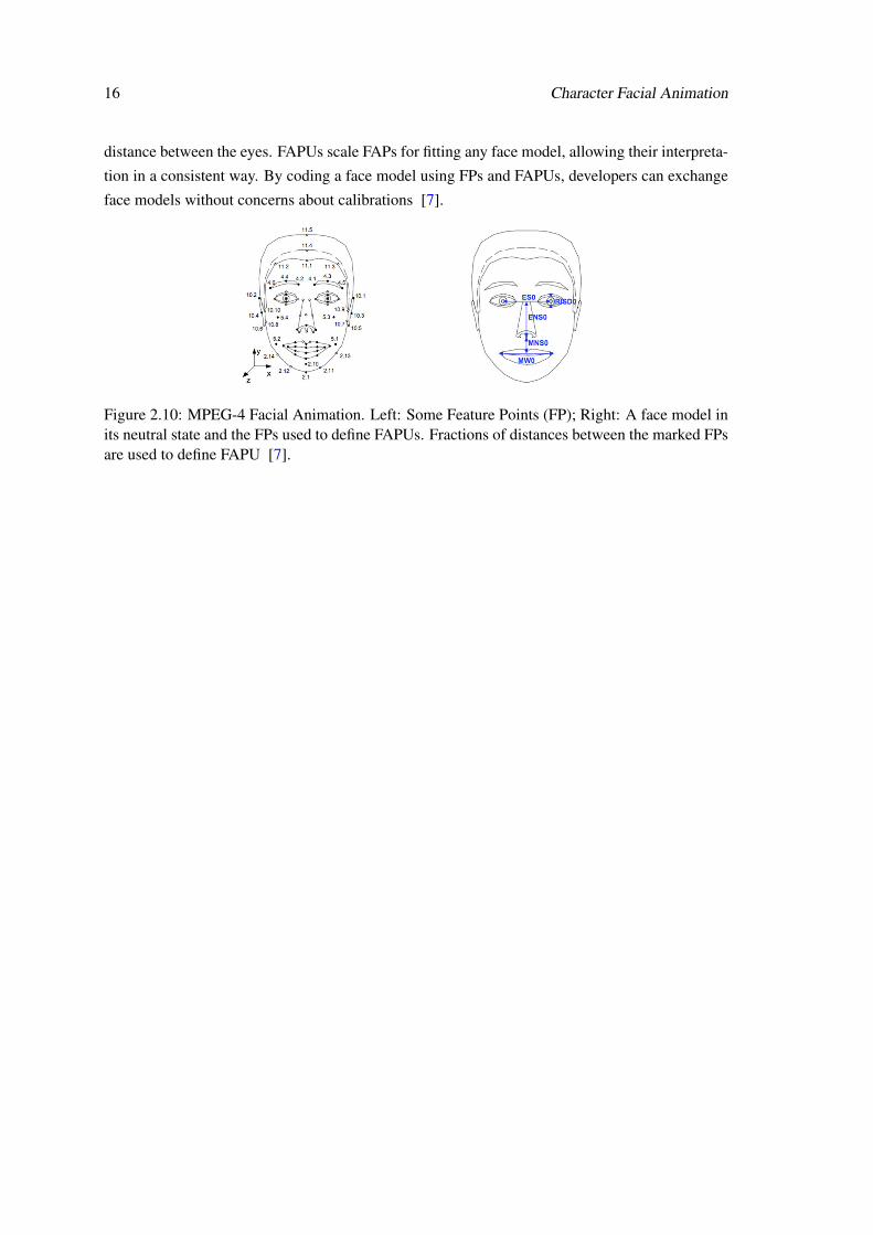
The MPEG-4 Facial Animation standard [43] specifies a face model in its neutral state and a
number of Feature Points (FP) that provide spatial reference to specific positions on a human face
such as major muscles and bones. It also defines a set of Facial Animation Parameters (FAP), each
corresponding to a particular facial action deforming the neutral face. Facial animation sequences
are generated by deforming the neutral face model according to some specific FAP values at each
time instant.
The standard defines 84 FPs, 66 low-level FAPs and 2 high-level FAPs, visemes and expres-
sions. Viseme is the visual counterpart of phonemes in speech while facial expressions consists of
a set of 6 basic emotions: anger, joy, sadness, surprise, disgust and fear. The low-level FAPs are
based on the study of minimal facial actions and are closely related to muscle actions, precisely
specifying how much a given FPs should move. All low-level FAPs are expressed in terms of the
Face Animation Parameter Units (FAPUs) which are fractions of key facial features, such as the
16 Character Facial Animation
distance between the eyes. FAPUs scale FAPs for fitting any face model, allowing their interpreta-
tion in a consistent way. By coding a face model using FPs and FAPUs, developers can exchange
face models without concerns about calibrations [7].
Figure 2.10: MPEG-4 Facial Animation. Left: Some Feature Points (FP); Right: A face model inits neutral state and the FPs used to define FAPUs. Fractions of distances between the marked FPsare used to define FAPU [7].
Chapter 3
Sketching Interaction
The way humans interact with computers has evolved at the same pace as the machines themselves.
Today, the barriers between users and devices are fading away with the development of new types
of interfaces. As touch screen devices become more common, this technology can provide an
accessible and natural interface for sketches - rapidly executed freehand drawings - to be used in
the modeling and animation processes as well as in collaborative systems.
This chapter presents the evolution of user interfaces and an overview of the technologies
and devices commonly referred as having "natural user interfaces". Then, it describes how new
approaches in the human-computer interaction can be used to ease the modeling and animation
processes through intuitive sketch-based interfaces. The chapter ends by presenting two common
ways of solving the problem of sketch recognition, allowing the use of drawings as means of input
to control computer devices, as an alternative to tradition buttons, menus and keyboard shortcuts.
3.1 Interactive Devices
Human-Computer Interaction (HCI), originally known as man-machine interaction, is a term
known since the early 1980s [47]. It examines the importance of usability and user-oriented
interface design meaning that if focus on improving interaction between users and computing
devices according to the needs and capabilities of both. Since the first digital computers were
programmed, using mechanical switches and plug boards, the ways in which people interact with
computers have evolved significantly and as more and more uses for technology came into play,
more and more types of interfaces were created to help bridge the barrier between man and com-
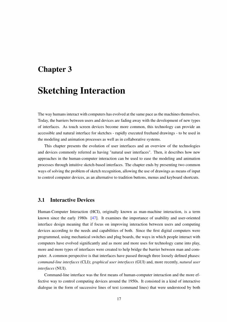
puter. A common perspective is that interfaces have passed through three loosely defined phases:
command-line interfaces (CLI); graphical user interfaces (GUI) and, more recently, natural user
interfaces (NUI).
Command-line interface was the first means of human-computer interaction and the more ef-
fective way to control computing devices around the 1950s. It consisted in a kind of interactive
dialogue in the form of successive lines of text (command lines) that were understood by both
17
18 Sketching Interaction
Figure 3.1: The evolution of interfaces.
users and computers. The interface was usually implemented with a command line shell, which
is a program that accepts commands as text input and converts them to appropriate system func-
tions. Today, CLIs are less used by casual users but often preferred by advanced ones, since they
generally provide a more concise and powerful means to control a program or operating system.
In the mid 60s, with the development of ultra large scale integrated circuits, high-resolution
displays and the appearance of the mouse, interfaces turned to a graphical approach. GUI are based
on metaphors, like the desktop metaphor (so called because windows are allowed to overlap, like
papers on top of a desk) and rely on a known set of user interface elements, commonly referred as
WIMP (Window, Icon, Menu, Pointer) [48].
3.1.1 Natural User Interfaces
Today, a new trend is gaining strength: NUI is an emerging paradigm shift that is reducing even
more the barriers between users and machines. The term is used to refer a user interface that is
invisible or becomes invisible to its users with successive learned interactions. The word "nat-
ural" is used because NUIs aim to enable users to interact with computers in the same way as
they interact with the world. They rely on the ability of a user to perform relatively natural move-
ments or gestures that they quickly discover to control the computer applications or manipulate
the on-screen content. Thus, novice users quickly progress to experts. NUIs take advantage of the
power of a much wider range of communication modalities, focusing on human abilities such as
touch, speech, handwriting, eye-gazing, motion and higher cognitive functions such as expression,
creativity, exploration, as well as combinations of them, forming multimodal interfaces.
But the design and development of the technology that support new NUIs is both conceptually
and practically very challenging and may require both novel software and hardware to allow input
from multiple and varied sources [49]. Traditional development environments, such as Microsoft
Visual Studio/.NET, Adobe Flash or Java, fall short of supporting uncommon input devices as
3.1 Interactive Devices 19
well as handling multi-user applications, for multi-touch interaction and collaborative work. To
overcome these issues, over the last few years a broad variety of heterogeneous and very spe-
cialized toolkits and frameworks have appeared like Microsoft Surface SDK [50], NUIGroup
Touchlib [51], a library for creating multi-touch interaction surfaces or GlovePIE [52], that orig-
inally started as a system for emulating joystick and keyboard input using a virtual reality glove
peripheral, but now supports many input devices. Few development environments that address the
new requirements are available, supporting novel input devices such as physical turntables, mixing
desks, multi-touch surfaces and simple vision tracking. Two examples are MAX/MSP [53] and
vvvv [54], which are graphical development environments for music and video synthesis that are
widely used by artist to create interactive multimedia installations.
The following sections present examples of devices commonly referred as having NUIs.
3.1.2 Multi-touch interfaces
Multi-touch devices consist of a sensing surface, like a trackpad or a touchscreen, as well as soft-
ware that recognizes two or more points of contact with the surface. This plural-point awareness is
often used to implement functionalities such as pinch to zoom or activating predefined programs.
Multi-touch technologies have a long history. The first documented multi-touch system was de-
veloped in 1982 by the University of Toronto’s Input Research Group [55]. It consisted of a
frosted-glass panel with particular optical properties so that finger pressure produced variable size
black spots on an otherwise white background. Using a camera, simple image processing allowed
multi-touch input.
In recent years the market witnessed a proliferation of multiple finger tracking products [56],
including many tablets, smartphones and digital tables. Bill Buxton presented a good overview
of the evolution of the multi-touch technology [57] since its early beginnings. The following
sections present some of the most relevant new trends and devices.
3.1.2.1 Multi-touch Tables
Multi-touch digital tables are tabletop displays that present the characteristics of multi-touch tech-
nology: a touchscreen and software to analyse the contact points. It is an innovative user-friendly
technology offered in nearly any shape or size to suit any requirement. Depending on its spec-
ifications, digital tables may allow users to interact with multimedia content the same way they
have interacted with physical objects using their hands, normal gestures or by putting real-world
objects on the table.
DiamondTouch
DiamondTouch [58] is a multi-user touch technology for tabletop front-projected displays
that supports small group collaboration, originally developed at Mitsubishi Electric Re-
search Laboratories (MERL) in 2001 [59] and later licensed to Circle Twelve Inc, in 2008.
It enables several different people to use the same touch-surface simultaneously without
20 Sketching Interaction
interfering with each other, or being affected by foreign objects left on the surface but its
most innovative feature is the ability to to identify which person is touching where. By
distinguishing between different users, the system can track a person’s input and behave
appropriately, controlling their access to certain functions
SMART Table
The SMART Table is the first multi-touch, multi-user interactive learning center designed
to stimulate collaboration among primary students. It works with both Mac and Windows
operating systems and is easy-to-clean, scratch-resistant and highly durable in order to suit
the needs of its young users. The SMART Table can be used together with other SMART
hardware and comes with an initial set of eight learning applications but many others are
available for download. The well-known 230i [60] model, with a blue top child appealing
look, presented a 27 inches multi-touch display supporting up to 6 users at one time. The
new SMART Table 442i [61] features a 42 inches (106.68 cm) surface with high-definition
1080p LCD display, supporting up to 40 simultaneous touches which enable up to eight
students to interact simultaneously and actively collaborate to achieve shared learning goals.
Microsoft PixelSense
Microsoft PixelSense [62], formerly called Microsoft Surface, is an interactive surface
computing platform that recognizes fingers, hands and objects placed on the screen to create
a natural user interface. It allows one or more people to use touch and real world objects
and share digital content at the same time.
Microsoft Surface 1.0, the first version of PixelSense, was announced on May, 2007 and
could recognize 52 simultaneous multi-touch points of contact in a 30 inches (76 cm) 4:3
rear projection display (1024x768). Sales of Microsoft Surface 1.0 were discontinued in
2011 in anticipation of the release of the Samsung SUR40 for Microsoft Surface and the
Microsoft Surface 2.0 software platform. The current version of PixelSense, the Samsung
SUR40 for Microsoft Surface was announced in 2011, and presents a 40 inches (102 cm)
16:9 LED backlit LCD display (1920x1080) with integrated PC and PixelSense technology.
3.1.2.2 Tablets
A tablet computer, or simply tablet, is a one-piece mobile computer, mainly controlled by touch-
screen via finger gestures or a virtual keyboard, removing the need for physical input hardware
components. The first commercial tablets appeared at the end of the 20th century and today many
models with different sizes and features are available on the market. Tablets are lightweight and
easier to carry than laptops while offer many of the same Web browsing capabilities. They are
usually used for consuming multimedia content, like movies, music and books, rather than for
creating content.
3.1 Interactive Devices 21
Apple iPad
The iPad is a line of tablet computers designed and marketed by Apple first released on
April, 2010. The wide range of capabilities and increased usability, battery life, simplicity
and overall quality of the first model, in comparison with competitor devices, earned the iPad
positive reviews which defined a new standard, revolutionizing the tablet industry. However,
some aspects, such as the lack of support for the Adobe Flash format were criticized. All
devices run on Apple’s iOS operating system, have built-in Wi-Fi and, some models present
cellular connectivity up to LTE. The most recent models, the new iPad and the iPad Mini
were released on November, 2012. Then new iPad [63] has a 9.7 inch LED-backlit multi-
touch retina display with 2048x1536 resolution at 264 pixels per inch (ppi).
Microsoft Surface
Microsoft Surface was the first name of the interactive surface computing platform now
known as Microsoft PixelSense. Today, this name is associated to a series of tablets de-
signed and marketed by Microsoft [64]. The Surface comes in two versions: one with
Windows RT (a special Microsoft Windows operating system designed to run on mobile
devices utilizing the ARM architecture), released on October, 2012 and another with Win-
dows 8 Pro with launching scheduled for February, 2013. Both tablets have high-definition
10.6 inches (27 cm) screens with an anti-fingerprint coating and 16:9 aspect ratio but have
different resolutions: 1366x768 pixels for the Windows RT model and 1920x1080 pixels for
the Pro model. One of the most useful features of Micrsoft Surface is the built in kickstand
on the back of the unit that enables the device to maintain an upright position and become
hands-free.
Google Nexus
Google Nexus is a line of mobile devices using the Android operation system produced by
Google along with an original equipment manufacturer (OEM) partner that, today, includes
smartphones and tablets (it also included a media-streaming entertainment device, Nexus Q,
that was unofficial dropped due to bad reviews). The first tablet of the series, the Nexus 7
[65], developed in conjunction with Asus was unveiled in June, 2012 and shipping started
the following month, being the first device to run Android version 4.1, nicknamed "Jelly
Bean". Even though this is one of the smaller tablets on the market, it includes an HD
touchscreen 7 inch (18 cm) display with 1280x800 pixel resolution. The second tablet of
the series, the Nexus 10 [66], was manufactured by Samsung and first released in November,
2012. It runs Android 4.2 ("Jelly Bean") operating system and features a 10.1 inch display
with 16:10 aspect ratio and 2560x1600 pixel resolution (300ppi), which in 2012, made it
the world’s highest resolution tablet display.
22 Sketching Interaction
3.1.3 Spatial Interaction
Multi-touch technology can enable natural user interfaces. However, most UI toolkits used to con-
struct interfaces with such technology are traditional GUIs that fail to achieve the "transparency"
desired for NUIs: our attention is projected to the multi-touch screen that remains distinguishable
from the background. This idea of integrating computers seamlessly into the world is not new.
In 1991, Mark Weiser, of Xerox PARC, published an article that outlined a vision of the next
generation of computation where he described a model of Ubiquitous Computing, or UbiComp,
where technologies "weave themselves into the fabric of everyday life until they are indistinguish-
able from it" [67]. At the time, there where no appropriate display systems that could work with
the full diversity of input and output forms required for this UbiComp approach. Today, we are
closer than ever to achieve it, with an emerging type of user interfaces that allow users to interact
with computing devices in entirely new ways, such as through the motion of objects and bodies,
demoting multi-touch technology to an old draft of natural user interfaces.
Kinect
Kinect [68] is a motion sensing input device by Microsoft for the Xbox 360 video game
console and Windows PCs. It was first announced in June, 2010 under the code name
"Project Natal" and released in North America on November of the same year. Kinect
competed with the Wii Remote Plus and PlayStation Move motion sensor controllers but
had a major advantage: this webcam-style add-on peripheral enabled users to control and
interact with the Xbox 360 without the need to actually touch a game controller, using
gestures and spoken commands. The device features a RGB camera, depth sensor and
multi-array microphone that allow full-body 3D motion capture, facial recognition and voice
recognition capabilities, changing the way people play games, watch TV and listen to music.
On June, 2011 Microsoft released the Kinect SDK, allowing developers to write Kinect-
based applications in C++, C# or Visual Basic .NET.
Leap Motion
Leap Motion is a breakthrough technology focused on bringing motion control to the desk-
top through a small USB peripheral. The inspiration for this new technology came to its
creators from the frustration surrounding 3D modeling using a mouse and keyboard versus
the simplicity of molding clay in the real world. The Leap Motion controller is designed
to rest on a desk in front of a monitor, creating an invisible 3D roughly 1.2 metre-square
interaction space inside which the device is advertised (through video demonstrations) to
track hands and fingers as well as tools such as pens, pencils, and chopsticks with very high
accuracy. Like Microsoft’s Kinect, the peripheral tracks human body gestures, and trans-
lates this movement into corresponding motions on a video display. According to David
Holz and Michael Buckwald, co-founders of the startup Leap Motion, its input device is
3.2 Sketch-based Interfaces Pipeline 23
accurate to within 1/100 of a millimeter and 200 times more sensitive than existing motion-
sensing technologies such as Microsoft’s Kinect. The release of the Leap Motion controller
is estimated for early 2013 but the company is accepting pre-orders on its website [69].
3.2 Sketch-based Interfaces Pipeline
User interfaces of modeling systems, such as Maya or Blender, have traditionally followed the
WIMP (Window, Icon, Menu, Pointer) paradigm [70]. But using these powerful applications can
be very difficult for a non-expert user that may need to explore a considerable amount of menus
and controls before executing a specific task. Significant learning time and effort is required in
order to create complex models and to memorize keyboard shortcuts. In order to simplify this
interaction model, recent research in modeling interfaces led to a new trend known as sketch-
based interfaces for modeling (SBIM). The idea is to automate the processes of sketch recognition
in order for sketching to be an effective means of input in computer modeling, replacing the
traditional buttons and menus. Sketching on paper has often been used in the early prototyping
stages of the design before its conversion into a 3D model. Automating or assisting this translation
could significantly reduce the time and effort needed to create complex models that usually turn
out to be a bottleneck in production pipelines. As sketching is natural and intuitive for humans that
can imbue so much meaning into a 2D drawing, SBIM can make 3D modeling systems accessible
to novice users. The human visual system interprets sketches with little effort, even when they are
not faithful representations of real-world objects. But getting a computer to mimic this ability is
a very difficult task. The main challenge of SIBM is to interpret the meaning of the input stroke,
understanding the user’s intention, in order to display the correct result. Based on Olsen et al.
[70], the pipeline of a sketch-based system is summarized in figure 3.2. The first step is to obtain
a sketch from the user (Sketch Acquisition), followed by a filtering stage to clean and transform
the sketch (Sketch Filtering). The process ends with the extraction of meaning from the sketch
(Sketch Interpretation).
Figure 3.2: The SBIM pipeline.
24 Sketching Interaction
3.2.1 Sketch Acquisition
The process of sketch recognition starts with the acquisition of a sketch from the user. This
is done through a sketch-based input device that ideally mimics, as close as possible, the feel
of freehand drawing on paper in order to exploit the user’s ability to draw. Although the most
common input device is the standard mouse, devices in which the display and the input device
are coupled (such as tablet displays) enable a more natural interaction. Despite the degree of
immersion provided by the chosen sketch input device, it must, at the bare minimum provide
positional information in some 2D coordinate system, usually window coordinates. The sampling
rate varies among the devices but in all, the sampled positions represent a linear approximation
of continuous movements, varying the space between them according to the drawing speed. The
space between samples tends to be smaller in parts drawn more carefully such as corners so this
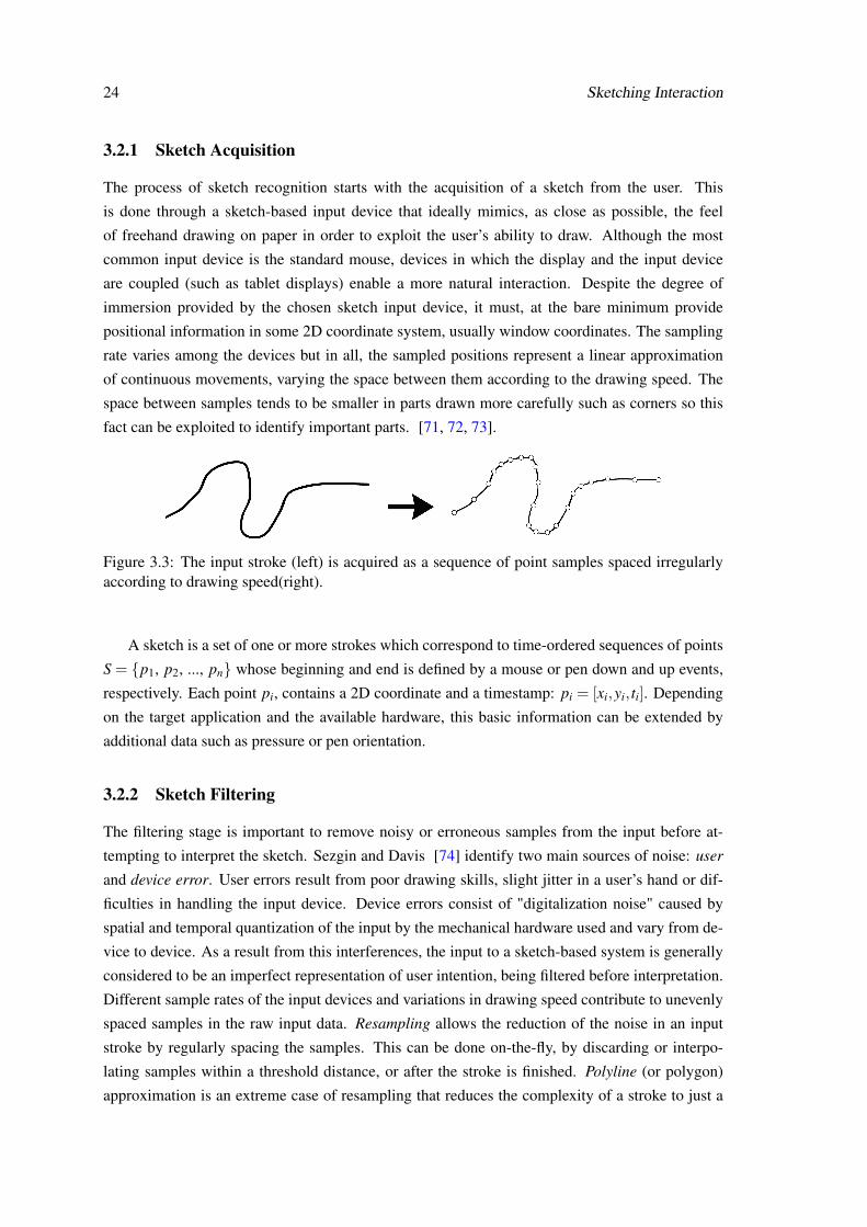
fact can be exploited to identify important parts. [71, 72, 73].
Figure 3.3: The input stroke (left) is acquired as a sequence of point samples spaced irregularlyaccording to drawing speed(right).
A sketch is a set of one or more strokes which correspond to time-ordered sequences of points
S = {p1, p2, ..., pn} whose beginning and end is defined by a mouse or pen down and up events,
respectively. Each point pi, contains a 2D coordinate and a timestamp: pi = [xi,yi, ti]. Depending
on the target application and the available hardware, this basic information can be extended by
additional data such as pressure or pen orientation.
3.2.2 Sketch Filtering
The filtering stage is important to remove noisy or erroneous samples from the input before at-
tempting to interpret the sketch. Sezgin and Davis [74] identify two main sources of noise: user
and device error. User errors result from poor drawing skills, slight jitter in a user’s hand or dif-
ficulties in handling the input device. Device errors consist of "digitalization noise" caused by
spatial and temporal quantization of the input by the mechanical hardware used and vary from de-
vice to device. As a result from this interferences, the input to a sketch-based system is generally
considered to be an imperfect representation of user intention, being filtered before interpretation.
Different sample rates of the input devices and variations in drawing speed contribute to unevenly
spaced samples in the raw input data. Resampling allows the reduction of the noise in an input
stroke by regularly spacing the samples. This can be done on-the-fly, by discarding or interpo-
lating samples within a threshold distance, or after the stroke is finished. Polyline (or polygon)
approximation is an extreme case of resampling that reduces the complexity of a stroke to just a
3.2 Sketch-based Interfaces Pipeline 25
few samples. After resampling, a sketch still contains a large number of sample points with little
meaning so it is common to fit the sketch to an equivalent representation. Fitting simplifies the
input data and the future comparison operations. Curve fitting is a simplification approach that
requires significant computation but produces fewer errors than polyline approximation. Another
option is least-squares polynomial fitting but the most common approach is to use parametric
curves like Bézier and B-spline curves. Fitting is more suitable for applications where precision is
desirable or assumed, such as engineering drawings. But this approach may inadvertently destroy
some important features of the sketch making it unsuitable for applications that support free-form
sketching and make few assumptions about the user’s intention. Oversketching allows the users
to sketch what they want and correct any made mistakes by sketching over the error. This system
then updates the sketch by cutting the region affected by the secondary stroke and smoothing the
transition between the old and the new segments.
3.2.3 Sketch Interpretation
The final step of the pipeline is the interpretation of the sketch, in which its meaning is translated to
a 3D modeling operation. In tradition systems (WIMP) every button or menu performs a specific
and pre-defined task but in sketch-based systems the freehand input is inherently ambiguous and
open to multiple interpretations. Olsen et al. propose a categorization of SBIM systems based on
the types of modeling operations performed by each one: creation systems automatically generate
3D models from 2D input sketches; augmentation systems use input strokes to add new details
to existing models and deformation systems use them to alter and existing models with editing
operation such as cutting, bending or twisting.
The problem of sketch recognition and interpretation has been solved by two standard ap-
proaches: gesture/feature-based classification and geometric-based classification.
3.2.3.1 Gesture-based Recognition
The first, and earliest, approach to sketch interpretation typically focus on how a sketch was drawn
rather than on what the final sketch actually looks like. Gesture-based systems require each shape
to be drawn in a particular style, making it a gesture, rather than a shape. Users have to learn how
to draw each symbol since stroke order, stroke direction and the number of strokes are determin-
ing factors for recognition. The goal of these systems is to match the input stroke (a sampling of
3D points in the form of x, y, and time) to one of a pre-defined set of gestures. Recognition is
performed based on a number of drawing-style features, such as the speed of the stroke, the start
and end direction of the stroke, and the total rotation of the stroke. This approach has the benefit
of using mathematically sound classifiers which produce fast and accurate classifications if users
draw shapes as defined. However, gesture-based systems are very sensitive to changes in scale and
26 Sketching Interaction
rotation and require user training in order to achieve good results.
Figure 3.4: Gesture-based recognizers typically focus on how a sketch was drawn rather than onwhat the final sketch actually looks like so stroke order is relevant.
The idea of interacting with computers via pen-based input began in the 1960s with Ivan
Sutherland’s Sketchpad [75]. It proved to be beyond its time as pen-based interfaces would not
catch until the 1990s. In 1991, Dean Rubine proposed a gesture recognition toolkit, GRANDMA,
which allowed single-stroke gestures to be learned and later recognized through the use of a linear
classifier [76]. Rubine proposed thirteen features which could be used to classify simple gestures
with an accuracy of 98% on a fifteen-class gesture set when trained with at least fifteen examples.
He also provided two techniques to reject ambiguous or non-gestures. Rubine’s work was later
extended in 2000 by Long et al. [77], who performed multi-dimensional scaling to identify corre-
lated features and ultimately found an optimal subset that consisted of eleven of Rubine’s features
features along with six of their own. Both of these works proved to perform well in recognizing
two-dimensional gestures but their accuracy is not ideal when applied to natural sketch recog-
nition problems because they put constraints on how users draw. A recent popular approach to
gesture recognition is known as the $1 recognizer [78]. This easy and cheap recognizer facilitates
the incorporation of gestures into user interface prototypes with about 100 lines of code. First, it
resamples the input stroke to remove drawing speed variation and aligns it based on an "indica-
tive angle" (that corresponds to the angle formed by the centroid and the gesture’s first point), to
provide rotation invariance. Then the gesture is scaled, non-uniformly, to a reference square and
translated to a reference point. Finally, the gesture results in a set of candidate point that must
be matched to a set of previously recorded templates that suffer the same transformations. This
method provides highly overall accuracy with minimal training and low computational overhead
but also presents some drawbacks as a result of its simplicity: it only recognizes unistroke gestures.
To overcome some of this problems, a significant extension to this approach was later presented
[79]: $N recognizer identifies gestures comprising multiple strokes and automatically generalizes
from one multistroke to all possible multistrokes using alternative stroke orders and direction.
3.2.3.2 Geometric-based Recognition
Because of the drawing constraints imposed by gesture-based recognition systems, more recent
approaches to sketch recognition shifted towards geometric-based techniques. Geometric-based
3.2 Sketch-based Interfaces Pipeline 27
recognizer focus on what the sketch looks like and less on how it was actually drawn, allowing
users to draw as they would naturally. These techniques are considered geometric because they
compare a stroke to an ideal representation of pre-defined primitives using geometric formulas.
They recognize low-level primitive shapes that can then be combined hierarchically to form more
complex shapes using specialized grammars like LADDER [80], a language presented by Tracy
Hammond and Randall Davis in 2005, to describe how sketched diagrams in a domain are drawn,
displayed and edited. It consisted of pre-defined shapes, constraints, editing-behaviours and dis-
play methods as well as a syntax for specifying a sketch grammar and extending the language,
ensuring that shape groups from many domains can be described.
The recognition of high level shapes depends on accurate low-level interpretations so many
geometric-based recognizers have been developed. In 2001, Sezgin et al. presented a three phase
system - approximation, beautification and basic recognition - that focused on interpreting the
pixels generated by the user’s strokes on an input device and producing low level geometric de-
scriptions such as lines, ovals and rectangles [81]. It used a novel approach to detect vertices in
sketched strokes. In 2003, Yu and Cai built a domain-independent system for sketch recognition
that used low-level geometric features [82]. Later, in 2008, Paulson and Hammond presenten
PaleoSketch, a system that can recognize eight primitive shapes, along with complex shapes, with
accuracy rates over 98.5% [83].
The advantage of geometric-based recognition systems is that they are typically more style-
independent as they allow users to sketch in a non-constrained manner, requiring no individual
training. However, geometric-based recognizers typically use numerous thresholds and heuristic
hierarchies which are not mathematically sound. This makes inferences about generalization hard
to determine because classification is not statistical. In addition, recognition accuracy is modest,
unless tuned for a specific domain.
Figure 3.5: Geometric-based recognizers identify low-level primitive that form more complexshapes.
SBIM systems often use interfaces based on gestural recognition: simple strokes are used as
input to specify commands and manipulate objects, directly or indirectly. The lack of numerous
complex menus may be less intimidating to a novice user but still requires some learning time and
effort to memorize what stroke corresponds to each operation.

28 Sketching Interaction
Chapter 4
Natural Sketching for Facial Animation
Realistic facial animation that fulfils the viewer expectations is very hard to achieve. Traditional
modeling and animation software, although very powerful, is complex and requires from the users
significant learning time to explore and master multiple menus and functionalities. With the evo-
lution of user interfaces, new approaches to the human-machine interaction model, that replace
traditional WIMP paradigm, have proven to be valid alternatives to ease the animation process.
Sketching on paper is often used in early prototyping stages of characters’ design. By taking
advantage of the fast propagation of natural user interfaces, sketching, as an intuitive means of
communication, can now be used further down the animation pipeline. As they allow a more
direct manipulation of 3D models, sketch-based interfaces reduce the complexity of otherwise
difficult tasks of deforming and animating multiple expressions of a character. And if sketch-
based software, that clearly recognizes people’s intentions, is combined with the convenience of
mobile devices, that require no intermediate input device other than the users fingers, a new range
of opportunities becomes available to non-experienced artist. This dissertation project aims to
explore this "natural sketching" approach for facial animation, based on mobile devices.
This chapter clarifies the challenges raised by this approach, presents the proposed solution
and describes the main tool that will be used. It ends by planning the future work for the next
semester.
4.1 Challenges
Highly realistic facial animation if nearly impossible to achieve [84]. Quality results are only
accessible to skilled artists through a slow, laborious and costly process that requires extensive
manual intervention. Thus, creating an intuitive and easy to use facial player for non-expert users
remains a challenge and if we add the possibility of allowing users to create and edit facial ani-
mations on mobile devices the complexity grows. Building software for mobile devices requires a
different approach than creating applications for desktop PCs. Mobile applications must explore
the opportunities offered by multi-touch and other natural user interfaces but never forgetting that
the hardware is not as fast and powerful as a computer with dedicated video card.
29
30 Natural Sketching for Facial Animation
This dissertation aims to tackle these problems and go even further, presenting a new approach
to allow collaborative work to be included in the animation process. Thus, several scenarios and
designs for the interface need to be analysed.
4.2 System Description
This dissertation projects aims for the deployment of a simple and intuitive timeline-based facial
animation application that will be suited for non-expert users. Starting with the sketching system
presented by Miranda et al. [13], that allows easy and interactive prototyping of facial poses by
drawing strokes on 3D mesh or on a virtual canvas, this application will be designed for the Apple
iPad and implemented using the Unity game engine.
It will include two modes: a standalone version for a single user and a collaborative environ-
ment that allows multiple simultaneous users.
4.2.1 Mode A: Standalone version
The standalone version of the application will be inspired by traditional media players, having a
timeline-based interface, but it will explore the simplicity and intuitiveness offered by multi-touch
mobile devices. The user will be able to manipulate a 3D character through free-hand drawing to
create different facial expressions, using his fingers in alternative to other external input devices.
By drawing directly over the parts of the model that he wants to deform, the user will experience
an interaction with the 3D model closer to the one he would get in reality, with a clay model, for
example. As the input drawings mimic the familiar experience of sketching on paper, the whole
interaction paradigm will be more natural and inviting for non-experienced users.
The produced expressions can, then, be saved, modified and dragged to a timeline, acting as
keyframes to generate an animated sequence. Once in the timeline, the poses can be re-ordered
or deleted. Its length can also be altered, varying the time that the character displays that specific
expression. An innovative feature of the standalone version of the player, is the possibility to
record sequences of sketches so that the resulting expression can be later reproduced.
4.2.2 Mode B: Collaborative environment
Two different modes are expected for this version (figure 4.1): one where each user plays the game
in an individual iPad and sees the result of the collaborative work in that same device, and other
where the produced result is shown in another device like a television, a projector or computer
screen. In either case, two alternatives for collaborative work will be examined. In the first case,
multiple users can modify the same model simultaneously, thus, an hierarchy of alteration power
needs to be defined since they cannot alter the same region at the same time. In the second case the
collaborative work is more limited since each user can only create facial expressions individually.
These facial poses are stored in a library that can be accessed by all so each user can drag them to
the timeline.
4.3 Tools 31
Figure 4.1: Two possible modes foreseen for the collaborative version of the application: (a)individual actions and the result of the collaborative work are displayed in each device; (b) theresults are displayed in an external device
4.3 Tools
The prototype system will be developed for the iPad using Unity engine.
4.3.1 Unity
Unity [85] is a cross-platform game engine developed by Unity Technologies. It is used to make
games for web plugins, desktop platforms, video game consoles and mobile devices that can be
deployed to 10 global platforms: Windows, Linux, Mac, Android, iOS, Unity Web Player, Adobe
Flash Player, PlayStation 3, Xbox 360 and Nintendo Wii. Unity’s game development ecosystem
features a powerful rendering engine with many intuitive tools, thousands of ready-made assets
and a knowledge-sharing Community. It also offers some platform-specific features that are very
useful because building games for devices like the iPhone and iPad requires a different approach
than creating desktop PC games. For mobile iOS devices, Unity offers, for example, a number
of scripting APIs to access the multi-touch screen, the accelerometer or the device geographical
location system and new content that can be used to implement in-app purchases.
4.4 Work Plan
Figure 4.2 shows the estimated duration of each stage of the development of this dissertation.
Although there might be some minor changes to the presented planning, no large deviation is
expected. The stages in red correspond to de development of the collaborative environment. Its
design is an important step of the project but the actual implementation is a low-priority objective
that will depend on the complexity of the remaining work.
32 Natural Sketching for Facial Animation
Stage 1. Background and State of Art: exploration of the current state of the art related to
facial character animation and interactive mobile devices;
Stage 2. Requirements and Functional Analysis (Standalone version): definition, design
and analysis of the system requirements including the development framework, prototype platform
and user needs for the standalone version.
Stage 3. Requirements and Functional Analysis (Collaborative version): definition, de-
sign and analysis of the system requirements including the development framework, prototype
platform and user needs for the collaborative environment.
Stage 4. System Architecture and Early Prototype (Standalone version): definition of the
core system modules and creation of a functional prototype to be used as a proof of concept of
the overall system for the standalone version. Special attention will be paid to the User Interface
design so early testing and validation can be performed.
Stage 5. System Architecture (Collaborative version): definition of the core system mod-
ules and design of adequate user interfaces for the collaborative environment.
Stage 6. Core technology development (Standalone version): implementation of the main
technology of the system: facial sketching for character modeling and animation player of the
standalone version.
Stage 7. System Prototype (Collaborative version): deployment of a simple prototype that
can be used as a proof of concept of the collaborative environment. 1
Stage 8. Final Application: development of the standalone facial animation application for
the iPad.
Stage 9: Testing and Validation: informal experiments of the system will be conducted with
young children to evaluate and assess the usability and quality of the application.
Stage 10: Dissertation writing and dissemination: after completion of the writing of the
dissertation, a scientific article will be written to demonstrate the results.
Expected deliverables for each stage:
S1.1. Report that fulfils the requirements of the course unit "EEC0035 - Preparation of the
MSc Dissertation" with literature survey, analysis of the state of the art, organisation of the work
1Low priority objective.
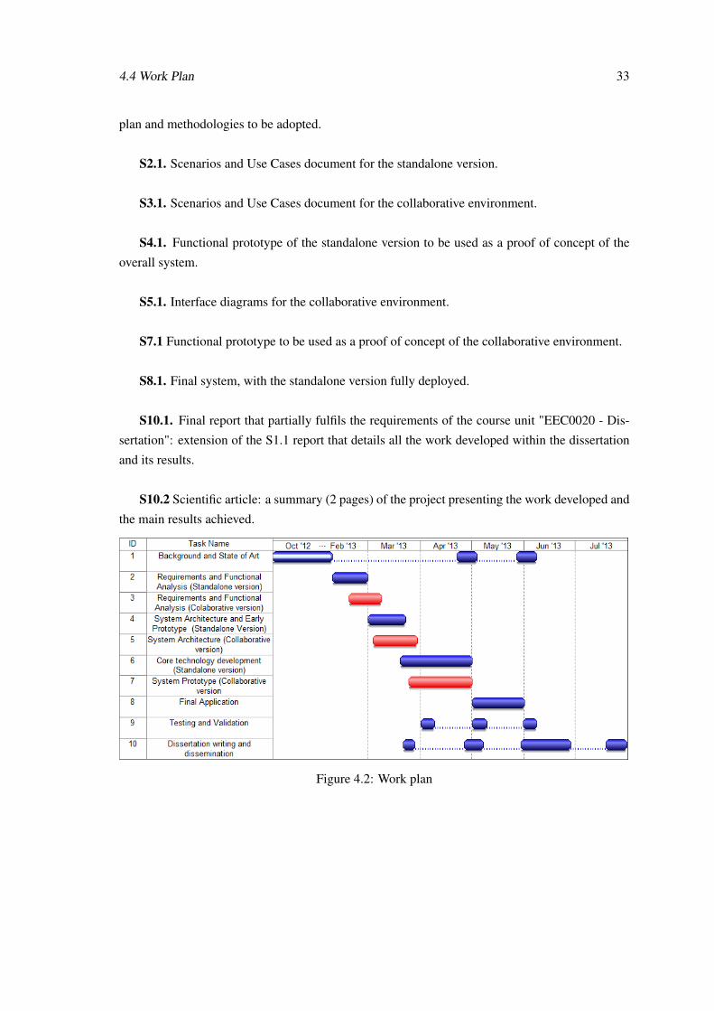
4.4 Work Plan 33
plan and methodologies to be adopted.
S2.1. Scenarios and Use Cases document for the standalone version.
S3.1. Scenarios and Use Cases document for the collaborative environment.
S4.1. Functional prototype of the standalone version to be used as a proof of concept of the
overall system.
S5.1. Interface diagrams for the collaborative environment.
S7.1 Functional prototype to be used as a proof of concept of the collaborative environment.
S8.1. Final system, with the standalone version fully deployed.
S10.1. Final report that partially fulfils the requirements of the course unit "EEC0020 - Dis-
sertation": extension of the S1.1 report that details all the work developed within the dissertation
and its results.
S10.2 Scientific article: a summary (2 pages) of the project presenting the work developed and
the main results achieved.
Figure 4.2: Work plan

34 Natural Sketching for Facial Animation
Chapter 5
Conclusion
Realistic animation of an expressive human face is still one of the greatest challenges in the field
of Computer Graphics and is only accessible to experienced artists that master complex software,
traditionally following the WIMP paradigm. The most recent trends in user interfaces, known as
"natural user interfaces" aim to enable users to interact with computers in the same way as they in-
teract with the world. Combining these new approaches with emergent technologies embedded in
interactive devices, that are now very common and accessible, such as tablets or digital tables, can
significantly ease the facial animation process and extend the possibility to produce high quality
animations to novice users.
This dissertation aims for the deployment of a functional sketch-based facial animation ap-
plication developed for a mobile device - the iPad. By the end of the project, a non-experienced
user will be able to intuitively deform and animate a 3D model, using simple sketches as means of
input to control this application.
This document summarizes the work done for the course unit "EEC0035 - Preparation of
the MSc Dissertation" in Electrical and Computer Engineering, presents the research done and
literature reviewed to support the project and outlines the proposed application. It also defines the
future work planned for the second semester of the current academic year in the context of the
course unit "EEC0020 - Dissertation".
35

36 Conclusion
References
[1] Zhigang Deng and Junyong Noh. Computer facial animation: A survey. In Zhigang Dengand Ulrich Neumann, editors, Data-Driven 3D Facial Animation, pages 1–28. Springer Lon-don, 2007. URL: http://dx.doi.org/10.1007/978-1-84628-907-1_1, doi:10.1007/978-1-84628-907-1_1.
[2] S. Villagrasa, A. Susín Sánchez, et al. Face! 3d facial animation system based on facs. 2010.
[3] Rob Bredow, David Schaub, Daniel Kramer, Matthew Hausman, Danny Dimian, and R. Stir-ling Duguid. Surf’s up: the making of an animated documentary. In ACM SIGGRAPH 2007courses, SIGGRAPH ’07, pages 1–123, New York, NY, USA, 2007. ACM. URL: http://doi.acm.org/10.1145/1281500.1281600, doi:10.1145/1281500.1281600.
[4] O. Alexander, M. Rogers, W. Lambeth, M. Chiang, and P. Debevec. Creating a photorealdigital actor: The digital emily project. In Visual Media Production, 2009. CVMP’09. Con-ference for, pages 176–187. IEEE, 2009.
[5] David Komorowski, Vinod Melapudi, Darren Mortillaro, and Gene S. Lee. A hybrid ap-proach to facial rigging. In ACM SIGGRAPH ASIA 2010 Sketches, SA ’10, pages 42:1–42:2,New York, NY, USA, 2010. ACM. URL: http://doi.acm.org/10.1145/1899950.1899992, doi:10.1145/1899950.1899992.
[6] W. GRUBB. Facial animation rig for delgo. Tutorial Notes, 12, 2009.
[7] K. Balci. Xface: Mpeg-4 based open source toolkit for 3d facial animation. In Proceedingsof the working conference on Advanced visual interfaces, pages 399–402. ACM, 2004.
[8] B. Paulson, P. Rajan, P. Davalos, R. Gutierrez-Osuna, and T. Hammond. What!?! no ru-bine features?: using geometric-based features to produce normalized confidence values forsketch recognition. In HCC Workshop: Sketch Tools for Diagramming, pages 57–63, 2008.
[9] LIFEisGAME. Learning of facial emotions using serious games, 2010. URL: http://www.portointeractivecenter.org/lifeisgame/ [last accessed 2013-01-27].
[10] FCT. Fundação para a ciência e a tecnologia. URL: http://www.fct.pt/ [last accessed2013-01-27].
[11] UT Austin|Portugal. Internationa collaboratory for emerging technologies (colab). URL:http://utaustinportugal.org/ [last accessed 2013-01-27].
[12] IT. Instituto de telecomunicações. URL: http://www.it.up.pt/ [last accessed 2013-01-27].
37
38 REFERENCES
[13] José Carlos Miranda, Xenxo Alvarez, João Orvalho, Diego Gutierrez, A. Augusto Sousa, andVerónica Orvalho. Sketch express: A sketching interface for facial animation. Computers& Graphics, 36(6):585 – 595, 2012. URL: http://www.sciencedirect.com/science/article/pii/S0097849312000416, doi:10.1016/j.cag.2012.03.002.
[14] Frederick I. Parke. Computer generated animation of faces. In Proceedings of the ACMannual conference - Volume 1, ACM ’72, pages 451–457, New York, NY, USA, 1972. ACM.URL: http://doi.acm.org/10.1145/800193.569955, doi:10.1145/800193.569955.
[15] K. Ritchie, J. Callery, and K. Biri. The Art of Rigging: A definitive guide to charactertechnical direction with Alias Maya. CG Toolkit, 2005.
[16] M. Mori. The uncanny valley. Energy, 7(4):33–35, 1970.
[17] D. Hanson, A. Olney, S. Prilliman, E. Mathews, M. Zielke, D. Hammons, R. Fernandez, andH. Stephanou. Upending the uncanny valley. In Proceedings of the National Conference onArtificial Intelligence, volume 20, page 1728. Menlo Park, CA; Cambridge, MA; London;AAAI Press; MIT Press; 1999, 2005.
[18] Canetti Y. Piretti M. Schleifer J., Scaduto-Mendola R. Character setup from rig mechanicsto skin deformations: A practical approach. SIGGRAPH ’02 Course Notes, 2002.
[19] Nikolaos Ersotelos and Feng Dong. Building highly realistic facial modeling and animation:a survey. The Visual Computer, 24:13–30, 2008. URL: http://dx.doi.org/10.1007/s00371-007-0175-y, doi:10.1007/s00371-007-0175-y.
[20] V. Orvalho, P. Bastos, F. Parke, B. Oliveira, and X. Alvarez. A facial rigging survey. InEurographics 2012-State of the Art Reports, pages 183–204. The Eurographics Association,2012.
[21] T. McLaughlin and S.S. Sumida. The morphology of digital creatures. In ACM SIGGRAPH,pages 05–09, 2007.
[22] V.C.T. Orvalho. Reusable facial rigging and animation: Create once, use many. PhD thesis,Universitat Politècnica de Catalunya, 2007.
[23] J. Fordham. Middle earth strikes back. Cinefex, 2003.
[24] Pushkar Joshi, Wen C. Tien, Mathieu Desbrun, and Frédéric Pighin. Learning controls forblend shape based realistic facial animation. In ACM SIGGRAPH 2005 Courses, SIG-GRAPH ’05, New York, NY, USA, 2005. ACM. URL: http://doi.acm.org/10.1145/1198555.1198588, doi:10.1145/1198555.1198588.
[25] A. Ward. Game character development with maya. New Riders, 2005.
[26] N. Burtnyk and M. Wein. Interactive skeleton techniques for enhancing motion dynamicsin key frame animation. Commun. ACM, 19(10):564–569, October 1976. URL: http://doi.acm.org/10.1145/360349.360357, doi:10.1145/360349.360357.
[27] J. P. Lewis, Matt Cordner, and Nickson Fong. Pose space deformation: A unified approachto shape interpolation and skeleton-driven deformation, 2000.
REFERENCES 39
[28] T.W. Sederberg and S.R. Parry. Free-form deformation of solid geometric models. In ACMSiggraph Computer Graphics, volume 20, pages 151–160. ACM, 1986.
[29] S. Coquillart. Extended free-form deformation: a sculpturing tool for 3D geometric model-ing, volume 24. ACM, 1990.
[30] K. Singh and E. Fiume. Wires: a geometric deformation technique. In Proceedings of the25th annual conference on Computer graphics and interactive techniques, pages 405–414.ACM, 1998.
[31] M.A. Warburton. Physically-based facial modelling and animation with wrinkles: 12 monthreport. 2011.
[32] Stephen M. Platt and Norman I. Badler. Animating facial expressions. SIGGRAPH Com-put. Graph., 15(3):245–252, August 1981. URL: http://doi.acm.org/10.1145/965161.806812, doi:10.1145/965161.806812.
[33] J. Osipa. Stop staring: facial modeling and animation done right. Sybex, 2010.
[34] John Lasseter. Principles of traditional animation applied to 3d computer animation. InProceedings of the 14th annual conference on Computer graphics and interactive techniques,SIGGRAPH ’87, pages 35–44, New York, NY, USA, 1987. ACM. URL: http://doi.acm.org/10.1145/37401.37407, doi:10.1145/37401.37407.
[35] Frederic Pighin, Jamie Hecker, Dani Lischinski, Richard Szeliski, and David H. Salesin. Syn-thesizing realistic facial expressions from photographs. In ACM SIGGRAPH 2006 Courses,SIGGRAPH ’06, New York, NY, USA, 2006. ACM. URL: http://doi.acm.org/10.1145/1185657.1185859, doi:10.1145/1185657.1185859.
[36] K. Waters and T. Levergood. An automatic lip-synchronization algorithm for synthetic faces.In Proceedings of The second ACM international conference on Multimedia, pages 149–156.ACM, 1994.
[37] F.I. Parke. A parametric model for human faces. Technical report, DTIC Document, 1974.
[38] Jun yong Noh and Ulrich Neumann. A Survey of Facial Modeling and Animation Tech-niques. 1998.
[39] D. Bennett. The faces of the polar express. In ACM Siggraph 2005 Courses, page 6. ACM,2005.
[40] V. Blanz, C. Basso, T. Poggio, and T. Vetter. Reanimating faces in images and video. Com-puter Graphics Forum, 22(3):641–650, 2003. URL: http://dx.doi.org/10.1111/1467-8659.t01-1-00712, doi:10.1111/1467-8659.t01-1-00712.
[41] W.L. Wooten and J.K. Hodgins. Simulating leaping, tumbling, landing and balancing hu-mans. In Robotics and Automation, 2000. Proceedings. ICRA’00. IEEE International Con-ference on, volume 1, pages 656–662. IEEE, 2000.
[42] I.D. Horswill. Lightweight procedural animation with believable physical interactions. Com-putational Intelligence and AI in Games, IEEE Transactions on, 1(1):39 –49, march 2009.doi:10.1109/TCIAIG.2009.2019631.
40 REFERENCES
[43] I.S. Pandzic and R. Forchheimer. Mpeg-4 facial animation. The standard, implementationand applications. Chichester, England: John Wiley&Sons, 2002.
[44] P. Ekman and W. V. Friesen. Facial action coding system: a technique for the measurementof facial movement. 1978.
[45] P. Ekman, W.V. Friesen, and J.C. Hager. Facial action coding system. A Human Face, 2002.
[46] Irfan Essa, Sumit Basu, Trevor Darrell, and Alex Pentland. Modeling, tracking and inter-active animation of faces and heads using input from video. In IN PROCEEDINGS OFCOMPUTER ANIMATION CONFERENCE, pages 68–79. IEEE Computer Society Press,1996.
[47] Achim Ebert, NahumD. Gershon, and GerritC. Veer. Human-computer interaction. KI -Künstliche Intelligenz, 26:121–126, 2012. doi:10.1007/s13218-012-0174-7.
[48] Daniel Wigdor and Dennis Wixon. Brave NUI World: Designing Natural User Interfacesfor Touch and Gesture. Morgan Kaufmann Publishers Inc., San Francisco, CA, USA, 1stedition, 2011.
[49] R. Harper. Being human: Human-computer interaction in the year 2020. Microsoft Re-search, 2008.
[50] Microsoft. Surfice sdk. URL: http://msdn.microsoft.com/en-us/library/ff727815(v=Surface.20).aspx [last accessed 2013-02-04].
[51] NUIGroup. Touchlib. URL: http://nuigroup.com/touchlib/ [last accessed 2013-02-04].
[52] Carl Kenner. Glovepie. URL: http://glovepie.org/glovepie.php [last accessed2013-02-04].
[53] Cycling ’74. Max/msp/jitter. URL: http://www.cycling74.com/ [last accessed 2013-02-01].
[54] vvvv: a multipurpose toolkit. URL: http://vvvv.org/ [last accessed 2013-02-01].
[55] N. Metha. A flexible machine interface. MA Sc. Thesis, Department of Electrical Engineer-ing, University of Toronto, 1982.
[56] Daniel Wigdor, Joe Fletcher, and Gerald Morrison. Designing user interfaces for multi-touch and gesture devices. In CHI ’09 Extended Abstracts on Human Factors in ComputingSystems, CHI EA ’09, pages 2755–2758, New York, NY, USA, 2009. ACM. URL: http://doi.acm.org/10.1145/1520340.1520399, doi:10.1145/1520340.1520399.
[57] B. Buxton. Multi-touch systems that i have known and loved. Microsoft Research, 2007.
[58] Circle Twelve Inc. Diamondtouch. URL: http://www.circletwelve.com/products/diamondtouch.html [last accessed 2013-02-04].
[59] P. Dietz and D. Leigh. Diamondtouch: a multi-user touch technology. In Proceedings of the14th annual ACM symposium on User interface software and technology, pages 219–226.ACM, 2001.
REFERENCES 41
[60] SMART Technologies Inc. Smart table 230i. URL: http://smart.lsk.hu/edu/tamogatas/letoltes/pdf/adatlapok/st230i.pdf [last accessed 2013-02-04].
[61] SMART Technologies Inc. Smart table 442i. URL: http://downloads01.smarttech.com/media/sitecore/en/pdf/products/table/mktg-913-rev05-ed-fs-table_final.pdf [last accessed 2013-02-04].
[62] Microsoft. Pixelsense. URL: http://www.microsoft.com/en-us/pixelsense/default.aspx [last accessed 2013-02-04].
[63] Apple Inc. ipad. URL: http://www.apple.com/ipad/features/ [last accessed2013-02-04].
[64] Microsoft. Microsoft surface. URL: http://www.microsoft.com/Surface/en-US[last accessed 2013-02-04].
[65] Google. Nexus 7. URL: http://www.google.com/nexus/7/ [last accessed 2013-02-04].
[66] Google. Nexus 10. URL: http://www.google.com/nexus/10/ [last accessed 2013-02-04].
[67] M. Weiser. The computer for the 21st century. Scientific American, 265(3):94–104, 1991.
[68] Microsoft. Kinect. URL: http://www.xbox.com/en-US/kinect [last accessed 2013-02-04].
[69] Leap Motion. Leap. URL: https://www.leapmotion.com/ [last accessed 2013-02-04].
[70] L. Olsen, F.F. Samavati, M.C. Sousa, and J.A. Jorge. Sketch-based modeling: Asurvey. Computers and Graphics (Pergamon), 33(1):85–103, 2009. cited By (since1996) 48. URL: http://www.scopus.com/inward/record.url?eid=2-s2.0-59249095193&partnerID=40&md5=79316233b31b419e83ca721757c11dfa.
[71] S. Saga. A freehand interface for computer aided drawing systems based on the fuzzy splinecurve identifier. In Systems, Man and Cybernetics, 1995. Intelligent Systems for the 21stCentury., IEEE International Conference on, volume 3, pages 2754 –2759 vol.3, oct 1995.doi:10.1109/ICSMC.1995.538199.
[72] Tevfik Metin Sezgin, Thomas Stahovich, and Randall Davis. Sketch based interfaces: earlyprocessing for sketch understanding. In Proceedings of the 2001 workshop on Perceptiveuser interfaces, PUI ’01, pages 1–8, New York, NY, USA, 2001. ACM. URL: http://doi.acm.org/10.1145/971478.971487, doi:10.1145/971478.971487.
[73] Tevfik Metin Sezgin, Thomas Stahovich, and Randall Davis. Sketch based interfaces: earlyprocessing for sketch understanding. In ACM SIGGRAPH 2006 Courses, SIGGRAPH ’06,New York, NY, USA, 2006. ACM. URL: http://doi.acm.org/10.1145/1185657.1185783, doi:10.1145/1185657.1185783.
[74] Tevfik Metin Sezgin and All Davis. Scale-space based feature point detection for digital ink.In In Making Pen-Based Interaction Intelligent and Natural, AAAI Spring Symposium, 2004.
42 REFERENCES
[75] Ivan E. Sutherland. Sketch pad a man-machine graphical communication system. InProceedings of the SHARE design automation workshop, DAC ’64, pages 6.329–6.346,New York, NY, USA, 1964. ACM. URL: http://doi.acm.org/10.1145/800265.810742, doi:10.1145/800265.810742.
[76] Dean Rubine. Specifying gestures by example. In Proceedings of the 18th annual confer-ence on Computer graphics and interactive techniques, SIGGRAPH ’91, pages 329–337,New York, NY, USA, 1991. ACM. URL: http://doi.acm.org/10.1145/122718.122753, doi:10.1145/122718.122753.
[77] A. Chris Long, Jr., James A. Landay, Lawrence A. Rowe, and Joseph Michiels. Visual simi-larity of pen gestures. In Proceedings of the SIGCHI conference on Human Factors in Com-puting Systems, CHI ’00, pages 360–367, New York, NY, USA, 2000. ACM. URL: http://doi.acm.org/10.1145/332040.332458, doi:10.1145/332040.332458.
[78] Jacob O. Wobbrock, Andrew D. Wilson, and Yang Li. Gestures without libraries, toolkitsor training: a $1 recognizer for user interface prototypes. In Proceedings of the 20th annualACM symposium on User interface software and technology, UIST ’07, pages 159–168,New York, NY, USA, 2007. ACM. URL: http://doi.acm.org/10.1145/1294211.1294238, doi:10.1145/1294211.1294238.
[79] L. Anthony and J.O. Wobbrock. A lightweight multistroke recognizer for user interfaceprototypes. In Proc. Graphics Interface, pages 245–252, 2010.
[80] T. Hammond and R. Davis. Ladder, a sketching language for user interface developers.Computers & Graphics, 29(4):518–532, 2005.
[81] T.M. Sezgin and R. Davis. Early processing in sketch understanding. Unpublished Master’sThesis, Massachusetts Institute of Technology, 2001.
[82] B. Yu and S. Cai. A domain-independent system for sketch recognition. In Proceedings of the1st international conference on Computer graphics and interactive techniques in Australasiaand South East Asia, pages 141–146. Citeseer, 2003.
[83] B. Paulson and T. Hammond. Paleosketch: accurate primitive sketch recognition and beau-tification. In Proceedings of the 13th international conference on Intelligent user interfaces,pages 1–10. ACM, 2008.
[84] George Borshukov, Jefferson Montgomery, and Witek Werner. Playable universal capture:compression and real-time sequencing of image-based facial animation. In ACM SIGGRAPH2006 Courses, SIGGRAPH ’06, New York, NY, USA, 2006. ACM. URL: http://doi.acm.org/10.1145/1185657.1185848, doi:10.1145/1185657.1185848.
[85] Unity Technologies. Unity. URL: http://unity3d.com/ [last accessed 2013-01-30].