Embed Size (px)
Citation preview

2 3 2 . 2
82 HA (-2.)
Working Paper Document de Travai l Documento de Trabajo
WP 9/11/82
HAND/FOOT PUMPS fo r Vi l lage Water Supply in Developing Countries
Part I I - Description of Pump Types
by H.P. Ba'nziger on behalf of Helvetas
St. Gall en 1982
SKAT VarnbuclstraBe 14, CH-9000 St.Gallen, Switzerland, Tel. 071 23 3481
S K A T Scliweizx-rische Kontaktstclle fur Angepafite Tcchnik am 1LE, Inst i tu l f i i r Lateinamerikaforschung und Enlwicklungs-zusannncnarhcit an dcr Hochschule St.Gallen
S K A T Swiss Center for Appropriate Technology at I LE, Ins t i tu te for Latin-American Research and for Development Co-operat ion, University of Saint-Gall
S K A T Centre Suisse pour ta Technologic Appropri6e a V I L E , [nstitut dc Recherche sur'l 'Amcriitue Latinc ct de Cooperation au Dc\eloppcmcnt, Universitc dc Saint-Gall
SKAT Ccntro Suizo de Tecnologia Aprop" " 1 " " n *•! 11 I7 - . _ . — Instituto de Investigacidn sobrc A ( p \ - 0 2 9 9 X? 0 AJ A
al Desarrollo, Urj ^ < - 5 ^ " < / & ^ H / j de Coopcracion al
W. 9-S"3^

Some Hand Pump Manufacturers
India
Charotar Iron Factory, opp. New Ramji Mandir, Anand, Gujarat. (makers of a pump similar to the Wasp).
Coimbatore Water and Agricultural Development Project, 69 Venkatasami Road, R. S. Puram, Coimbatore 641002.
(makes Jalna type pumps). Dandekar Bros Ltd, Shivaji Nagar Factory Area, P.O. Sangli, Maharashtra.
(Jal Javahar pump, also similar to the Wasp). Gujarat Small Industries Ltd, Nanavati Estate, near Chakudia Mahadeo, R3khial, Ahmedabad-23. (makers of the Kirti pump). JPSR Company (Mittra Das Ghose & Co.), Howrah. near Calcutta, (makes low-lift and deep well hand-pumps). Kirloskar Bros Ltd, Kirloskarvadi, Dist. Sangli, Maharashtra.
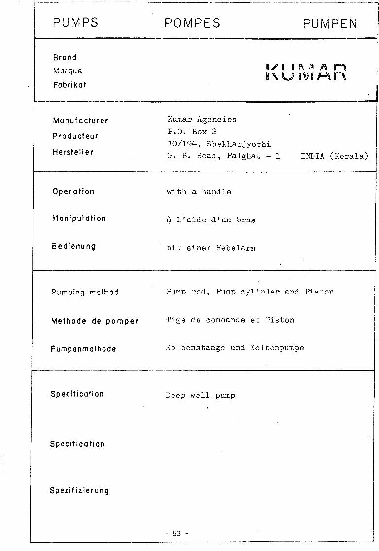
(makers of the Kareri deep-well hand pump, many other products). Kumar Industries, P.O. Edathara 678611, via Palghat, Kerala.
(several types of low-lift and deep-well hand pump). Lifetime Products Corporation, Industrial Area, Jodhpur.
(makers of a pump similar to the Wasp, but with detailed differences). •Marathwada Sheti Sahayya Mandal, Jalna. Dist. Aurangabad, Maharashtra.
(originator of the Jalna hand pump; non-commercial manufacture). Maya Engineering Works, Calcutta.
(known for the Maya No, 6 low-lift hand pump for shallow wells). Mohinder & Co, Kurali, Dist. Ropar, Punjab.
(low-lift hand pumps). *Senco Industries, A-I2, Coimbatore Private Industrial Estate, Coimbatore-21.
(commercial manufacturers of Jalna type pumps, and other kinds). •Sholapur Well Service, 560/59 South Sadar Bazaar, Civil Lines, Sholapur-3, Maharashtra, (makers of a re-designed Jalna hand-pump - see figure 3). •Vadala Hand Pump, Marathi Mission, Ahmednagar, Maharashtra.
(non-commercial maker of a Jalna type pump; the Jalvad). •Water Supply Specialists Private Ltd, Post Box 684, Bombay-1.
(makers of the Wasp deep-well hand pump).
Other Indian pumps have included the Patel, the Mahasagar, and the Economy, all with conventional pump-head assemblies. The India Mark II hand-pump is manufactured by several of the above firms; for details, write to UNICEF-WES, 11 Jor Bagh, New Delhi 1 10003.
Africa
ABI Pumps, Abidjan Industries, B.P. 343, 45 Rue Pierre et Marie Curie, Abidjan, Zone 4c, Ivory Coast.
(make Pompe Alternative - ABI type M, no details). Comptoirs Sanitares de Madagascar, B.P. 1104, Tananarive, Malagasy Republic. •Craelius Terratest Ltd, P.O. Box 40090, Nairobi, Kenya. SAFICOCI, B.P. 1117, Abidjan, Ivory Coast.
Shallow Wells Project, Shinyanga, Tanzania. (pump factory in operation from April 1976 making Uganda type pumps).
Siscoma, B.P. 3214, Dakar, Senegal. (make various types of pump, some of French design).
Western Countries
Barnaby Climax Ltd, White Ladies Close, Little London, Worcester WR1 1PZ, England.
(makers of Climax pumps). Briau S.A., B.P. 43 , 37009 Tours Cedex, France.
(makers of the Africa, Classique and Royale pumps). Consallen Structures Ltd, 291 High Street, Epping, Essex CM16 4BY, England.
(makers of Consallen pumps). •Dempster Industries Inc., P.O. Box 848, Beatrice, Nebraska 68310, U.S.A.
(deep-well hand-pump, model 23F; simple and inexpensive). •Etablissements Mengin, Zone Industrielle d'Amilly, B.P. 163, 45203 Montargis-France.
(makers of the Vergnet pedal-operated pump). H.J. Godwin Ltd, Quenington, Cirencester, Gloucestershire GL7 5BX, England.
(fly-wheel drive, conventional and experimental hand-pumps). GSW Limited, Hill Street, Fergus, Ontario, Canada.
(makers of Beutty pumps). Lee Howl and Co. Ltd. Tipton, West Midlands. England.
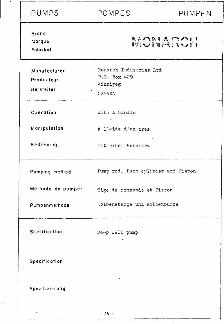
(low-lift pitcher spout and other hand-pumps). Monarch Industries Ltd, P.O. Box 429, Winnipeg, Canada.
(makers of Reatty pumps). •Mono Pumps Engineering Ltd, 1 Sekforde Street, London EC1, England.
(makers of the unique, low-maintenance Monolift hand-pump).
( 'denotes pumps useJ by, or on trial with UNICEF).
- 1 -

PUMPS
Brand
Marque
Fabrikat
Manufacturer
Producteur
Hersteller ode r
Operation
Manipulation
Bedienung
Pumping method
Methode de pomper
Pumpenmethode
Specification
Specification
Spezifizierung
POMPES PUMPEN
IMfM A M A D 5 / O
I n d u s t r i a l & A l l i e d S a l e s P r i v a t e L imi ted (INALSA) Surya K i r a n , 19 Kas turba Gandhi Marg New Delh i 11O0O1 INDIA
. B a l a j i I n d u s t r i a l and A g r i c u l t u r a l C a s t i n g s PO Box 1634, Secunderabad 3 INDIA
wi th a h a n d l e
a l ' a i d e d ' u n b ra s
mit einem Hebelarm
Pump rod and Cyl inder
Tige de commande e t P i s t o n
Kolbenpumpe mit Kolbens tange
Deep w e l l hand pump *

r« 360 — — 1190
NDIA MARK
Q
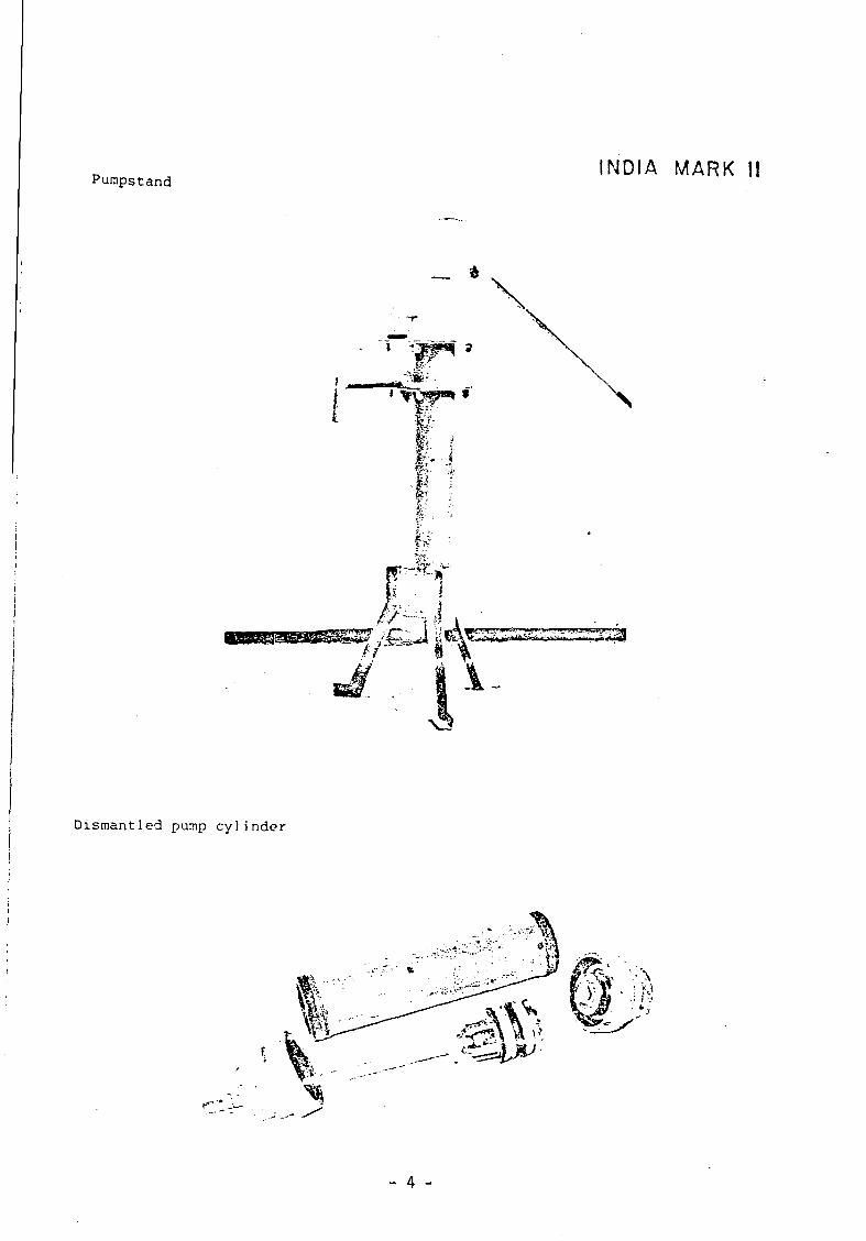
Purapstand INDIA M A R K II
__ *
v
fir*?*-,
\
i
1-
Dismantled pump cylinder
f"
- 4 -

INSPECTION COVER
CHAIN ANCHOR
CHAIN COUPLING
CONNECTING ROD GUIDE BUSH
RISER PIPE HOLDER
AXLE. WASHER. NUT & CHECK NUT
CONNECTING ROD CHECK NUT
LEVEL OF PLATFORM
CASING PIPE MINIMUM 100 1.0.
RISER PIPE 32 N. B. CONNECTING ROD 12 $
INDIA MARK II
- 5 -

SPECIFICATIONS
Particulars
Water d e p t h - optimum
Cylinder I D . Stroke Strokes per minute
Discharge per stroke (does not vary wi th depth) Discharge per hour
Unit
metre
mm mm nos. litres Imp. gallons litres Imp. gallons
Amount
30-33
63.5 100 40-50
0.32 0.07
800-1000 170-210
When the cylinder of the pump is installed at a water depth of 25 metres and more, the weight of connecting rods (12 mm dia.) and water column provides a positive downward stroke. In case of installation at less than 25 metres but more than 15 metres, the corresponding loss in weight of connecting rods can be made up by use of heavier rods (16 mm dia.) in order to provide a positive downward stroke.
Since this pump works on the principle of positive displacement it can function virtually at any wator depth beyond 25 metres.
90 *
rUh
HEX. NUT M 12.
RUBBER SEATING.
LEATHER CUP WASHER"
RUBBER SEATING.
SEALING RING.
REDUCER CAP_
.RISER PIPE 32N.B.
^PLUNGER ROD 12
.REDUCER CAP
.SEALING RING
.PLUNGER YOKE "BODY .UPPER VALVE SEAT
UPPER VALVE "GUIDE
-SPACER
.LEATHER CUP WASHER
.FOLLOWER
.CYLINDER BODY
BRASS LINER
RUBBER SEAT "RETAINER
CHECK VALVE GUIDE
CHECK VALVE SEAT
> * •
3000
^
M 12 x 1 75 THREAD
-LOCK NUT M 12
1 2 $
T 20
_L 50
U L
r WELD
.HEXAGONAL COUPLING
XJ
T 19
NOTE. ALL DIMENSIONS ARE IN MM UNLESS OTHERWISE MENTIONED.
- 6 -

4
INTRODUCTION EXPORTS Hand Pumps are the most economical means of providing water supply in rural and outlying urban areas. The conventional hand pumps being used in India for the past several decades are made from cast iron and have several drawbacks, such as low discharge, inefficient operation requiring greater manual effort, shorter life span and inability to work at depths beyond 8 metres. To overcome these drawbacks and to provide rural India wi th a .more dependable product, we. at INALSA, have developed the India Mark II Deep Well Hand Pump with the close cooperation and guidance of an international agency.
The Pump has the following salient features :
•Capable of pumping water wi th great ease from depths of 25 metres to 60 metres.
— Sturdy design to withstand continuous operation by larger communities for longer periods.
—Very nominal maintenance cost. Maintenance can be done by relatively unskilled personnel.
— Easy installation. —Fully covered to avoid contamination of water by external
sources. —Reasonable price.
A WORD ABOUT INALSA INALSA is well known in India for high quality light engineering products. The company, along with its two associates, is engaged in the manufacture of several products—including India Mark II Hand Pumps, household knitting machines, precision tools for the engineering industry, special purpose machines and marketing of automobile ancillaries and engineering products like graded and non-graded castings.
The production of Deep Well Hand Pumps was started in the •<?ar 1977, and now INALSA is the largest manufacturer of
ese pumps in India.
INALSA—A NAME THAT MEANS QUALITY India Mark II Deep Well Hand Pumps are manufactured in a wel l equipped factory in New Delhi, staffed with highly trained and skilled personnel. Great emphasis is laid on quality control, and rigid standards are maintained to ensure, a flawless product that wi l l provide trouble-free service year after year.
In addition to our own quality control team, our products are also tested by an internationally known British firm, specializing in the inspection of engineering goods. The exacting requirements of this agency have helped us in constantly improving our quality. No pump is approved without a thorough inspection of incoming materials and meticulous checks at every stage of manufacture. In addition, every pump is carefully examined to ensure distortion-free, leak-proof welding and an external finish of the highest quality.
Additionally, the pumps are continuously subjected to field trials so that data regarding their functioning is constantly available for future improvements.
India Mark II Deep Well Hand Pumps,manufactured by INALSA,have already been exported to the fol lowing countries : - S u d a n . Zaire, Upper Volta, Togo. Benin, Ethiopia, Uganda,
Kenya & Botswana in Africa. -Bu rma , Bangladesh, Indonesia & Phillipines in Asia. — Haiti in West Indies.
ADVANTAGES The ingenious designof India Mark II Deep Well Hand Pump, incorporating a long and heavy handle, ball-bearings and chain, results in several advantages : * A mechanical advantage of approximately 8:1 in the handle
bar lever, coupled with the differential weight on the tv . sides of the fulcrum point, gives a moment ratio of ovei 30:1 which ensures effortless operation. Even a 10-year-old child can easily operate the pump.
* Use of sealed ball-bearings further adds to the operational ease and ensures years of trouble-free performance.
* Use of high quality raw materials and close machining tolerances guarantees long life even under continuous use. The pump has a life span of over 150 million strokes— which works out to approximately 20 years if used for 8 hours every day.
* All materials used are indigenous and supply of spare parts is assured.
* As already mentioned, the design overcomes all the undesirable features of conventional cast iron hand pumps.
* Can be installed in multi-storeyed buildings. * Can be easily adapted to motorised operation. * Can be adapted for shallow well operation wi th minor
modifications.
DESCRIPTION The hand pump consists of 3 major assemblies :
1. Pump head assembly 2. Cylinder assembly 3. Connecting rod assembly The three assemblies mentioned above form a complete pump ready for installation, except for the rising main (Gl pipes) which can also be supplied by us if required.
1. Pump Head Assembly Figure 1 shows the details of pump head assembly. A part of the connecting rod is also shown in the figure although this forms a separate assembly by itself. The pump head is supplied in attractive hammertone green paint finish, except for the bottom portion which is painted bright red up to the level where it is to be embedded in the ground. This is basically done for easy installation. Water tank is completely hot dip galvanised and in addition painted from outside to harmonise with the rest of the pump. Bottom inside portion of the conversion head epoxy painted to prevent rusting.
Pumps can also be supplied in a fully galvanised condition.
- 7 -
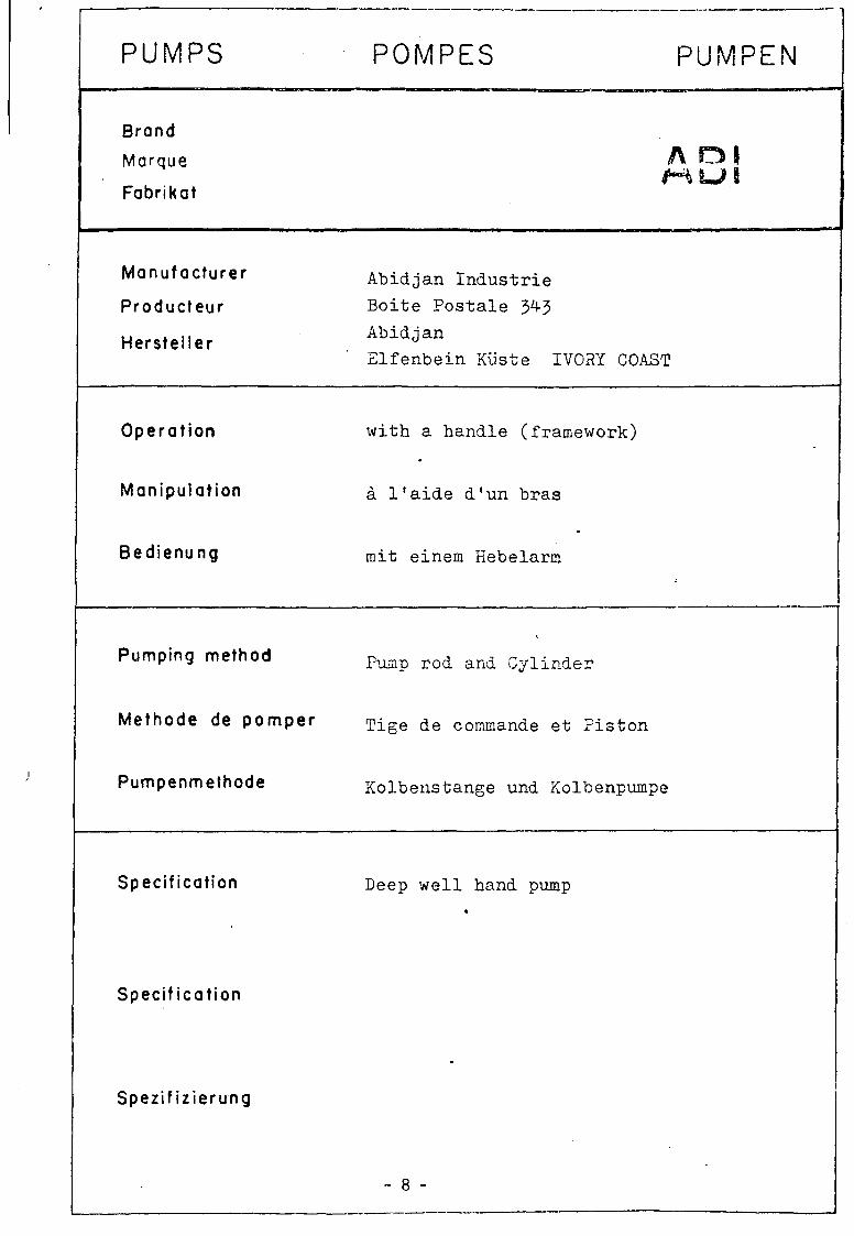
PUMPS
Brand
Marque
Fabrikat
Manufacturer
Producteur
Hersteller
Operat ion
Manipulation
Bedienung
Pumping method
Methode de pomper
Pumpenmethode
Specification
Specification
Spezifizierung
POMPES PUMPEN
A CM H U . I
Abidjan I n d u s t r i e B o i t e P o s t a l e 34-3
Abidjan
E l f e n b e i n Kiiste IVORY COAST
wi th a hand le (framework)
a l ' a i d e d ' u n b r a s
rait einem Plebeians
Fump rod and Cy l inde r
Tige de commande e t F i s t o n
Kolbens tange und Kolbenpumpe
Deep w e l l hand pump *
- 8 -

•J. ABI PUMP
630 —
B
V
950
i I E3
9 -

Pumpstand
ABI PUMP
TYPE M
: — i
s
'••'C\ X N f-X
'X - f¥rm • * s -=' >> "
••#£ ^ ^
Dismantled pump cylinder
l*&k
- 10

PUMPS
Brand
Marque
Fabrikat
Manufacturer
Producteur
Hersteller
Operat ion
Manipulation
Bedienung
Pumping method
Methode de pomper
Pumpenmefhode
Specification
Specification
Spezifizierung
POMPES PUMPEN
rnMOAi i CM
C o n s a l l e n S t r u c r u r e s Ltd
291 High S t r e e t Epping
.' .Essex CM 16 4 BY UNITED KINGDOM •
wi th a h a n d l e
a l ' a i d e d ' u n b r a s
mit einem Hebelarm
Pump rod and Cy l inde r
Tige de commande e t P i s t o n
Kolbens tange una kolbenpumpe
Deep w e l l hand pump
1
- 11 -

CONSALLEN PUMP
- 12 -

Pumpstand
CONSALLEN PUMP
MODEL L D 5
•;<j>a».">'WJ«,«n'. M.D. i j t , .
Dismantled pump c y l i n d e r
*«f! • spS" • ^ ^ \
O

PUMPS
Brand
Marque
Fabrikat
Manufacturer
Producteur
Hersteller
Operat ion
Manipulation
Bedienung
Pumping method
Methode de pomper
Pumpenmefhode
Specification
Specification
POMPES PUMPEN
S o f r e t e s Mengin
Zone I n d u s t r i e l l e d 'Ami l l y B .P . 16$ 45203 Montarg i s FRANCE
F o o t - o p e r a t e d
p a r p r e s s i o n du p i e d
mit F u s s p e d a l
H y d r a u l i c d r i v e n system
Hydropompe
Diaphragma-Pumpe
Deep w e l l pump «
Niveau s t a t i q u e merae a u - d e l a de 7O ra de p ro fondeu r
I
Spezifizierung Einsatz bis /O m hydrostatische Hone
- 14 -

POMPE VERGNET
I9S
i: i 280 — I
14 «
IT
W
1085
r •! 58S
- 140 -J I
', /
15

Sa simplicity (due a sa conception) garantit I'approvisionnement en eau.
1 Concue specialement pour les pays ou I'eau est rare . Elle fonctionne des an nees sans probleme.
JL Son entretien, d'une extreme simplicity, est a la portee des non-techniciens. Les quelques pieces d'usure a remplacer periodiquement sont peu couteuses.
C'est le seul systeme qui permette d'equiper un meme forage de plusieurs pompes, assurant une meilleure valorisation du point d'eau.
Commande au niveau du sol, facilement accessible pour I'entretien
Circuit hydraulique de commande entierement separe du refoulement
Niveau statique meme au-dela de 70 mde profondeur
Corps de pompe immergeen acier inoxydable (aucun entretien necessaire)
L'hydropompe Vergnet permet ainsi {'utilisation des forages dans les meil-leures conditions. Avec elle, les respon-sables savent que leurs programmes de forages seront menes a bonne fin.
Clapet de refoulement ferme
Clapet de refoulement ouvert
Le manchon se retracte Le manchon s'allonge
Clapet d'aspiration ouvert Clapet d'aspiration ferme
Aspiration: la pedaie Refoulement: lapedale remonte le manchon se descend. On exerce une retracte : I'eau est aspiree pression hydraulique en dans le corps de pompe en circuit ferme sur !e man-acier inoxydable. chon elastique qui se dilate
et refoule I'eau vers la surface
Le manchon dilatable (brevete) assure un fonctionnement sans problemes A chaque coup de pedaie correspond une dilatation du manchon
et un volume d'eau pompee d'environ 1/3 de litre 16

OrinCe c/<f r?fcu/cm<*nt
Pfac/of . Su.oport rcjuf . SU.op<
Pvrcorx/s ' S+o/or "
Tuyau c/e reroute merit
Cfop^f' c/t retouUm&nl
Boiti<?r d? rocvorja>m<rnt,
Corp3 c/e pompe
Protection c/f cr^p/ne
Po/hnee
POMPE VERGNET
<&&*^~
Pec/ah
Bulees basses
Ecroo ck quic/a<j*
COrnmctncJe 7 ^ Cy'incrr* <J?
Circuit c/c reomorcoq*
7u\j&t/ c/f common a(?
T~ rParcords
'Seprar*
(P,
*tu
refaulemcnt
T
n
Ctqpct c/'a-sp/ro'h'on
o-r<?c crjpine
17 -

Profondeur
10 metres
30 metres
40 metres
50 metres
Type de tete Type de corps Tuyau de commande
-4C2ou4C1
4C1
Tuyau de refoulement
Debit moyen en l/h
2 6 x 3 2 -
Poids (en kg)
Tete de pompe Corps de pompe
4C2
18 9
4C1
18.5 9
SES AVANTAGES Pose en molns d'une heure : I'emploi de canalisations en polyethylene flexible haute densite, la maniabilite et la legerete du corps de pompe et du systeme de commande hydraulique per-mettent I'installation en moins d'une heure sur un forage prepare. Sans materiel de levage : un homme et un aide suffisent.
Moyens d'lnterventlon legers : I'ou tillage d'entretien tresreduit: I cle plate (livree avec la pompe, pour lentretien courant), 1 cle a griffe, 1 tournevis (pour les revisions plus importantes) permet de venir entretenir la pompe avec n'importe quel moyen de transport.
L'utilisateur peut assurer lui-meme lentretien, dans la majority des cas : Corps immerge : pas de mecani-que, pas de frottement, done pas d'usure, pas de corrosion. Seules pieces en mouvement, les clapets, le manchon caoutchouc Le manchon fonctionne dans les conditions optimum : a labri des UV et immerge dans I'eau. II a subi les tests de fatigue les plus severes.
Tete de pompe : toutes les pieces d*usure y sont rassemblees et sont directement accessibles : - guide de pedale, - segments de piston. II s'agit de pieces peu couteuses, remplacables en quelques minutes.
Puita ferme = eau propre : une wi condition d'hygiene essentielle
Pendant des annees, on peut compter sur cette pompe simple et economique.
- 18 -

PUMPS POMPES PUMPEN
Brand
Marque A j T A I T I C7 V ^ 1 — 1 Hi l L - L - / X
Fabrikat
Manufacturer
Producteur
Hersteller
Operation
Manipulation
Bedienung
Pumping method
Methode de pomper
Pumpenmethode
Specification
Specification
Spezifizierung
E t s Pompes Guinard S.A.
179, Boulevard S a i n t - D e n i s B .P . No 320
92400 Courbevoie FRANCE
F o o t - o p e r a t e d
p a r p r e s s i o n du p i e d
mi t Fus speda l
H y d r a u l i c d r i v e n system
corps de pompe immergee au toamorcant a c l a p e t s r e n f o r c e s
Diaphragma-Fumpe
Deep w e l l pump »
Niveau s t a t i q u e meme a u - d e l a de 50 m de p rofondeur
E i n s a t z b i s 50 m h y d r o s t a t i s c h e Hone
- 19 -

[?DIWI fa
une pompe a pied autoamorgante toute simple...
> .-.f.v-V '
n -i i i
Sa simplicity permet
a un entretien reduit
a une installation rapide et peu couteuse
3 un point d'eau economique
?• une longue ydureede vie
Ce materiel convient tout particulierement aux points d'eau isoles ;Afrique - Extreme-Orient)
tete robuste etanche au sable
^
debit 1 m3/heure a 30 metres
forage economique 4"
0
*0;
: : .. &t o
• U &
pompe volumetrique a pied sans cylindre piston utilisant une enceinte deformable
i « Or"*' - * ^ V
Si
: • * • •
« %
corps de pompe immergee autoamorcant a clapets renforces
c •o'c
°~«s;9
^r** 0 8 * Of
ft
i b
- 20 -
1130 02-80

COURSES CARACTERISTIQUES
DESCRIPTION
Le cylindre piston d'une pompe clas-sique a ete remplace par une enceinte en caoutchouc specialement etudiee. Lorsque cette enceinte est tendue, elle diminue de volume, refoulant I'eau a la surface; lorsqu'elle revient a son volume initial, il y a aspiration. La colonne du tuyau (3/4") a la double fonction de tendre I'enceinte grace au levier et d'apporter I'eau a la surface.
I
SPECIALISTE MONDIAL DU POMPAGE, vous apporte son experience pour resoudre les problemes d'approvisionnement en eau des zones isolees. • par ses produits specialement adaptes, (pompes solaires,
pompes a pied). # par sa cooperation pour I'installation des pompes
et la formation des techniciens. © par les fabrications locales
50 % des composants de ces pompes a pied peuvent etre fabriquees sur place, dans le pays.
dans le monde premier constructeur Frangais de pompes
8 USINES - 19 FILIALES - 300 POINTS DE VENTE
Siege social : Ets POMPES GUINARD S.A.
179, boulevard Saint-Denis 92400 COURBEVOIE B.P. N': 320 - 92402 Courbevoie Cedex
Tel. : 788.50.52 (20 lignes groupees) - Telex 610.592 Guinardcourb R.C. : 73 B 6919 Paris - S.I.R.E.T. 569801897-00053
l/h
1200
1000
800
600
400
200
6C coups/nr.n
50 coups/mn
40 coups/mn
10 20 30 40 50 metres
- 21 -

PUMPS
Brand
Morque
Fabrikat
Manufacturer
Producteur
Hersteller
Operation
Manipulation
Bedienung
Pumping method
Methode de pomper
Pumpenmethode
Specification
Specification
Spezif izierung
POMPES PUMPEN
D C T D A 8 L 1 l \ U
Petropump Carl V/estmans Vag 5 S- 13300 Sal t s jobaden SWEDEN
with a handle
a l ' a i d e d 'un bras
mit einem Hebelarm
Diaphragmatic hose as pumping element
corps de pompe immergee autoamorcant a c l ape t s renforces
Diaphragma-Pumpe
Deep well pump *
- 22 -

PETROPUMP

PETROPUMP
Pumpstand Operating Mechanism
— < : !
b
\
¥k^i"
.1 k '-•-v-XUta*.
.{
~i
v. "• . > — "
Wv
\i--1
H* $;
V
': "*-'"'':
•>I • ,"a , I
5
*y
V.V
- 24 -

PUMPS
Brand
Marque
Fabrikat
Manufacturer
Producteur
Hersteller
Operat ion
Manipulation
Bedienung
Pumping method
Methode de pomper
Pumpenmethode
Specification
Specification
Spezifizierung
POMPES PUMPEN
C U I M V A MO A s J 6 IIS V 8 f-<U ^\Jt-%
Shinyanga Shallow Wells P r o j e c t P .O. Box 168
Shinyanga i
TANZANIA
wi th a h a n d l e
a l ' a i d e d ' u n b ras
mit einera Hebelarm
Pump r o d , Pump c y l i n d e r and P i s t o n
Tige de commande e t P i s t o n
Kolbens tange und Kolbenpumpe
Pumps a r e used for t h e f o l l o w i n g d e p t h s :
4" c y l i n d e r up to a p p r o x i m a t e l y 10 m 3" c y l i n d e r up t o a p p r o x i m a t e l y 20 m 2" c y l i n d e r up t o a p p r o x i m a t e l y J>0 m
- 25 -

SHINYANGA PUMP
- 26 -

2- esp
4"-2" reducer screwed on
4" pvc cylinder lackel
4" 2 " pvc reducer. cemented
rubber ball 80 mm dia
counter weight snd length of-stroke •£• limiter
screwed bar . (b'^ce iixil
13Cmrr\
l 1 / 2 " 9SP
i l , , ' • 75 mm „ 90 mm :
90/75 mm dia pvco'pe
malleable flange
10 mm
foot val»e D assembly
(see fig 34)
2" U " _ reducing socket
I s " B S P
© 60/50 Celeron
2 " 1 " - . _ reducing socket i
3 - 2 " reducing socket
removed
2"-1X" reducing bush
BSP
3" 2 " reducing socket
I . - •
i
• - 0 90/76 ABS
— V foot valve 3(sernb!y 2"• 1 Jf" reducing-1 1 * " foot valve
bush assembly C D
IX "BSP
0 114/100-4-Celeron
ABS or nylon disc
2 " C Y I I N 0 E R 3" CYL INDER
i 1 t
L-Ixfootvalve assembly
4" CYLINDER
PUMP CYLINDERS 4 " 3" and 2" DIAMETERS
| ^ # f
27 -

h
2" 1(7" reducer
2" threaded pipe
double acting rubber piston ring with step!
2" cap
1 ,, /7"BSP G I pipe
l 1 ' 2 " BSP
• # '-2 BSP
d'SCb^rqp
_. 30.mm^ 2 - 8SP 90 Tim
-
dnubl* aceno rubber piston ring with steel co'e
3 mm dta • spacer
strip approx V 2 " wide
discharge opening
_ double acting rubber piston ring with steel core
11/2" BSP
75.mm
- - ( - "
M16-C )
JI i ;
75 mm
o
PUMP PISTON ASSEMBLIES FOR 4", 3" and 2" CYLINDERS
- 28 -

? G I CJD
Cr Nt Mo rrnq
rube?' "f><:
malleable Hinge
I 11/2- 2
4 3 mm dii
C». Ni Mo nrwj
130 mm_
i l ' ip wf l f l r t ' to bushing
-li br*c« 'rxl opening
13 in total) l ' / 2 " BSPtoUt lKM
^ Q x
LQJ LJ
it
ni ^37 5 mm ^
E
4 9 0 / 7 6 ABS
nylon of
ABS disc
2.5 i 6 mm strip
due .alvc
D«'bu nan
rubber
r
U; ^ 2 7 5 mm _
J 4 _BSP thrtad^
F
FOOT-VALVES FOR 4 " , 3" and 2" CYLINDERS
!Ta»v •^~,i.._ij»-~iv-,??9wh.. I ~" I ) N
- 29 -

PUMPS POMPES PUMPEN
Brand
Marque
Fabrikat
Manufacturer Morogoro Wells C o n s t r u c t i o n P r o j e c t P .O. Box 261
Mcrogoro
• TANZANIA
Producfeur
Herstel ler
Operat ion w i th a v e r t i c a l moveable pump head ( s e t . o f p i p e s w i t h i n which a s p r i n g i s f i t t e d )
Manipulation a l ' a i d e d ' u n coup de main (mobile verticale)
Bedienung mit Handgriff zum auf- und abbewegen
Pumping method Pump rod, Pump cylinder and Piston
Methode de pomper T i g e d e commande et Piston
Pumpenmethode Kolbenstange und Kolbenpumpe
Specification Pumps are used for the following depths:
4" cylinder up to approximately 6 m 3" cylinder up to approximately 10 m 2" cylinder up to approximately 20 m
Specification
Spezif izierung
30 -

« 400 *
i>
U3»
-fe=
11 300
mzz JZl
1060
KANGAROO PUMP
31
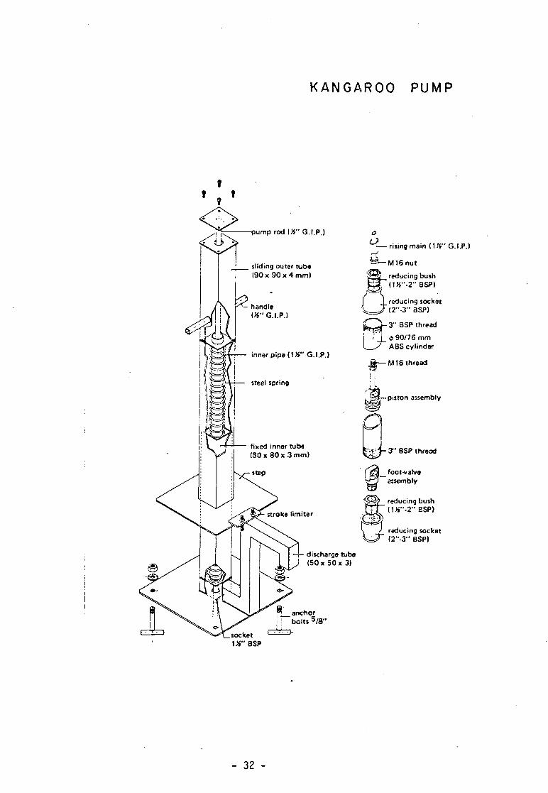
KANGAROO PUMP
pump rod (%" G.I.P.)
sliding outer tube ( 9 0 x 9 0 x 4 mm)
handle (K" G.I.P.)
inner pipe (Mi" G.I.P.)
fixed inner tube (80 x 80 x 3 mm)
stroke limiter
anchor bolts 5 / 8 "
-—rising main (Mi" G.I.P.)
^ — M 1 6 n u t
reducing socket (2"-3" BSP)
w ^ _ reducing bush E3~(1X"-2"BSP) o
^ ^ J - 3 " BSP thread
0 90/76 mm ABS cylinder
& — M 1 6 thread
;i M—piston assembly
'kA K p J - 3" BSP thread
foot-valve assembly
reducing bush d » " - 2 " BSP)
reducing socket (2"-3" BSP)
discharge tube (50 x 50 x 3)
socket 1tf"BSP
- 32 -

PUMPS
Brand
Marque
Fabrikat
Manufacturer
Producteur
Hersteller
Operat ion
Manipulation
Bedienung
Pumping method
Methode de pomper
Pumpenmethode
Specification
Specification
Spezif izierung
POMPES PUMPEN
D i l l C A S %J> IU. W f3**
A p p a r e c c h i a t u r e I n o s s i d a b i l i p e r l a Dinamica d e i F l u i d i Via Genova, 10
58100 G r o s s e t o ITALY
wi th a hand l e i
i a l ' a i d e d ' u n b r a s
rait einem Hebel
P i s t o n e lement on t h e s u r f a c e and an e l a s t i c p u l s a t i n g ; e lement below t h e l e v e l of t h e wa te r i n t h e w e l l Element a p i s t o n s u r l a s u p e r f i c i e du t e r r a i n e t un element e l a s t i q u e p u l s a n t a u - d e s s o u s du n iveau de 1 ' e au dans l e p u i t
Kolbenpumpe iiber T e r r a i n und Diaphragraa-Element u n t e r Wasser
Deep w e l l pump up t o 30 m e t r e s
Niveau s t a t i q u e meme a u - d e l a de 30 m de p ro fondeur
E i n s a t z b i s 30 m h y d r o s t a c i s c h e riohe
- 33 -

APPARECCHIATURE INOSSIDABILI PER LA DINAMICA DEI FLUIDI
Via Genova, 10 - 58100 GROSSETO (ITALY) - Tel. (0564) 21.272 - Telex 500433 FLX
SERVICE EXPORT BERTHOIJO S.A. VEVEY Bureau (?• 0 2 1 / 5 2 77 77
24, rue de I'Union 1800 Vevey
HAND PUMP FOR DEEP WELLS
SA (brevettata)
5 1
This revolutionary pump for deep wells (up to 30 metres) consists simply in a piston element on the surface and an elastic pulsating element below the level of the water in the well. This patented system which exploits the particular characteristics of water columns in a state of oscillation has facilitated an extreme facility of construction. The two elements one above ground level and one below the level of the water are connected to one another by one simple pipe (irrigation type) of normal rigid plastic construction.
— No moving parts below grond level. — Can be mounted without help of specialists. — Can be used for normal and artesian wells. — Is delivered complete with rapid connections for pipe. — Capacity 600- lOOO litres/hour. — Depth to 30 metres.
No moving parts below ground level!
Nessun organo in movimento al di sotto del livedo del terreno.
34

HAND PUMP FOR DEEP WELLS
'TULSA 3" (brevettata)
This revolutionary purnp for deep wells (up to 30 metres) consists simply in a piston element on the surface and an elastic pulsating element below the level of the water in the well. This patented system which exploits the particular characteristics of water columns in a state of oscillation has facilitated an extreme facility of construction. The two elements one above ground level and one below the level of the water are connected to one another by one simple pipe (irrigation type) of normal rigid plastic construction.
— No moving parts below grond level. — Can be mounted without help of specialists. — Can be used for normal and artesian wells. — Is delivered complete with rapid connections for pipe. — Capacity 600-1000 litres/hour. — Depth to 30 metres.
No moving parts below ground level!
POMPE A MAIN POUR LES PUITS PROFONDS
UL8A3" (brevetee)
Cette pompe revolutionnaire pour les puits profonds (jusqu'a 30 metres) consiste tout simplement en un element a piston sur la superficie du terrain et un element ela-stique pulsant au-dessous du niveau de l'eau dans le puits. Ce systeme brevete qui ex-ploite les characteristiques des colonnes d'eau en etat d'oscillation a rendu possible une construction d'une semplicite extreme. Les deux elements dont l'un au-dessus du terrain et l'un au-dessous du niveau de l'eau sont joints l'un a I'autre par le moyen d'un seul tuyau en plastique renforce du type utilise pour 1'irrigati.on,
— Pas de pieces en mouvement au-dessous du niveau du terrain. — Peut etre montee sans 1'intervention de specialistes. — Peut etre utilised pour les puits normaux et les puits artesonaux. — Livree complete de connections rapides pour tuyaux — Debit: 600-1000 litres par heure. — Profondeur jusqu'a 30 metres.
Pas de pieces en mouvement au-dessous du'niveau du terrain!
APPARECCHIATURE INOSSIDABIL1 PER LA D1NAMICA DEI FLUIDI
Via Genova, 10 - 58100 GROSSETO (ITALY) - Tel. (0564) 21.272 - Telex 500433 FLX
- 35 -

PUMPS
Brand
Marque
Fabrikat
Manufacturer
Producteur
Hersteller
Operation
Manipulation
Bedienung
Pumping method
Methode de pomper
Pumpenmethode
POMPES PUMPEN
Pompes G-ril lot Rue de l1Observance B.P. 118
• 84-007 Avignon Cedex FRANCE
with a handle
a ' 1 ' a i d e d 'un bras
mit einem Hebel
Pump rod, Pump cy l inde r and Pis ton
Mecanisme au so l a s p i r a n t ou a sp i r an t fou lan t , P i s ton dans le pu i t e t Clapet de pied dans 1'eau
Kolbenstange und Kolbenpumpe
Specification Deep well pump up to 15 metres
Specification Pompes pour p u i t s profonds 15 metres
Spezifizierung E insa t s b i s 15 m hydros ta t i sche Hone
- 36 -

POfUPE/ GRILLOT
NOTICE N 185
POMPES POUR PUITS PROFONDS
8 a 15 METRES
Plan d'installation
Mecanisme au sol aspirant ou aspirant foulant
TRINGIAGE : Diametre 8 mm par longueur de 3 m. ou 1,5 m. (avec ecrou long et contre-ecrou.
piston- ) 0 X
Clapej de pied « C r e p i n e >
33 /42 eventuel
- 37 -

W'V-1 •--,'..Ly"'1'-^^- -.'•"' *r.nsiiJ^.]lw*iajayty'.'""
5>>
. ^ ^ ~ ///UN : i- - J ; .-L. ; / 1 !•
ELLE A SA PLACE PARTOUT a la vil ie comme a la campagne. a la ferme comme a I usme cu Sur les chancers EHe se D'ete a toutes uti l isations usages domes-tiques divers (pompes d'evier. de buanderie. 6-i cterr .e de jardin). pompes d'amorcage. d eou 'Sece" ' . de vidange. de bateau, de tran-cnees. etc EMe pompe aussi b'en les eau* pures QU*. 'es eau* usees, le punn. les eau» de savon j i n s i que les alcools. vm. biere. Cidre. vmaigre. mouts. confitures. saumure. etc
ET ELLE SE PLACE P A R T O U T
FAC1LEMENT, RAPIDEfVIENT ! Vove i ci-contre queiques types courants de fixation
1 Sur corrueres a scellement
2 Sur equerres perrnettant la pose contre une c l c s o n un poteau. un arbre. dans un bateau, etc
3 Sur guatre pieds de la hauteur voulue
4 S'mpiement vissee sur le tube
TOUTE TUYAUTERIE LUI CONVIENT
Per. piomb. cuivre. rmc. toies gres ou caoutchouc piast ique. tout se raccorde faci iemeni a cette pompe
SON D E M O N T A G E EST I N S T A N T A N E
Un seui boulon a enlever pour visiter clapet d 'aspi 'at ion. piston et corps de pompe
CHCIX DU DiAMETRE DU PISTON SELON LA PROFONDEUR DE L'EAU
Debit minute
- 38 -
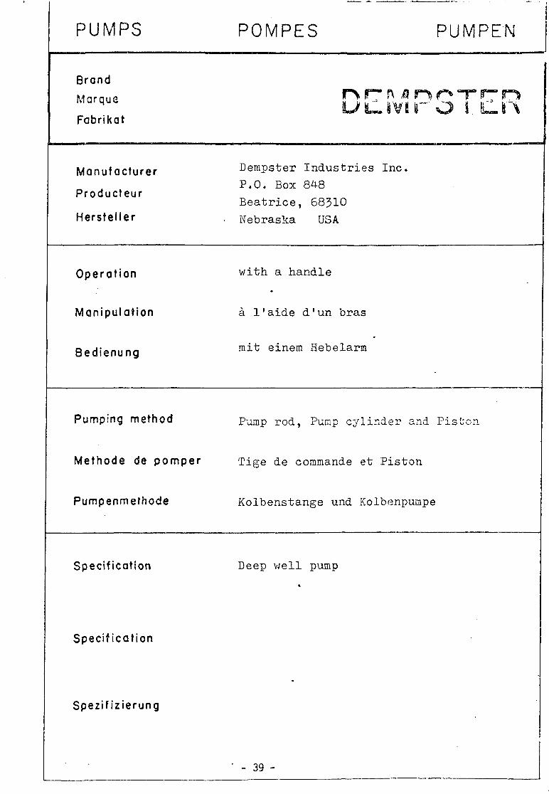
PUMPS POMPES PUMPEN
Brand
Marque
Fabrikat
nrMnorrn tlivir o i. Cn
Manufacturer Dempster Industries Inc.
P.O. Box 848
Beatrice, 68310 Hersteller . Nebraska USA
Producfeur
Operat ion w i t h a h a n d l e
Manipulation a l ' a i d e d ' u n b r a s
Bedienung rait einem Hebelarm
Pumping method p -^p r o < i j p u m p c y l i n d e r and P i s t o n
Methode de pomper
Pumpenmefhode
Specif ication
Speci f icat ion
Spezif iz ierung
T ige de commande et P i s t o n
Ko lbenstange und Kolbenpumpe
Deep w e l l pump
' - 39 -

DEMPSTER PUMP
/*"ry
n ' .f
ti ;:
Rising man I 4 ASP
40

Punp! ;tand
DEMPSTER PUMP
TYPE 23F (CS)
,. I jr-.. - v
. * -*-;-s-^>,-. -,-*•••..*- ' ; • • * - '
fassijSte*** 132&fagBM .wr»>r»' ' * '
Dismant L e d pump cy l inde r
fmtmmfmmmmwmi i>"WK
- i f / * ^
»n-r»-hi«B«i»»H«riifwi' Tn' ....^ -^y
i ^ j j ^"
1_5 y
rr^ m^
- 41 -

PUMPS
Brand
Marque
Fabrikat
Manufacturer
Producteur
Herstel ler
Operat ion
Manipulat ion
Bedienung
Pumping method
Methode de pomper
Pumpenmethode
Specif ication
Speci f icat ion
Spezif iz ierung
POMPES PUMPEN
RFATTY IUM^ lira, #~* li S S
GSW L i m i t e d
H i l l S t r e e t
Fergus
O n t a r i o CANADA
w i t h a handle
a 1 ' a i d e d ' u n bras
m i t einem Hebelarm
Pump r o d , Pump c y l i n d e r and P i s t o n
T ige de commande et P i s t o n
Kolbenstange und Kolbenpumpe
Deep w e l l pump
- 42 -
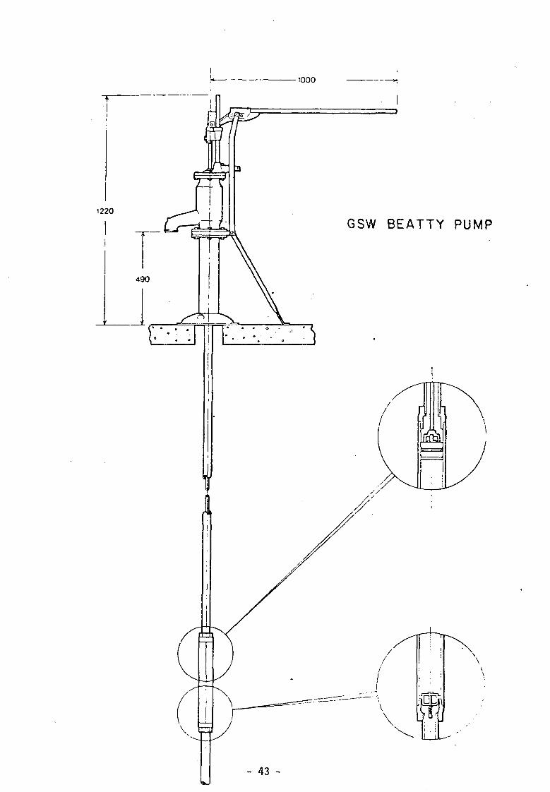
•1000
GSW BEATTY PUMP

GSW BEATTY PU
MODEL 1205
Purapstand
Dismantled pump cyUnder
**** ' ' «!**
*<*¥&y"i

Pumpstand operating mechanism
Uffl • V
% * If^A
GSW BEATTY PUMP
- 45 -
PUMPS
Brand
Marque
Fabrikat
Manufacturer
Producteur
Hersteller
Operat ion
Manipulation
Bedienung
Pumping method
Methode de pomper
Pumpenmefhode
Specification
Specification
Spezifizierung
t
POMPES PUMPEN (
Monarch I n d u s t r i e s Ltd
P .O. Box 429
Winnipeg
CANADA
wi th a h a n d l e
a l ' a i d e d ' u n b ra s
mit einem Hebelarm
Pump rod , Pump c y l i n d e r and P i s t o n
Tige de commande e t P i s t o n
Kolbens tange und Kolbenpumpe
Deep w e l l pump *
- 46 -

MONARCH P3 PUMP
- 47

Pumpstand
o
,i
1 f~?*m">Mr
s. o
- *
:x
MONARCH P3
PUMP
1
Dismantled pump cylinder
^ ^ \
- 48 -

Pumpstand operating mechanism
MONARCH P3 PUMP
- 49 -

PUMPS
Brand
Marque
Fabrikat
Manufacturer
Producteur
Hersteller
Operat ion
Manipulation
Bedienung
Pumping method
Methode de pomper
Pumpenmefhode
Specification
Specification
Spezifizierung
!
POMPES PUMPEN
B a t t e l l e Memorial I s t i t u t e
505 King Avenue
Columbus, Ohio 43201
• USA
wi th a h a n d l e
a 1 ' a i d e d ' u n b r a s
mi t einem Hebelarm
Pump r o d , Pump c y l i n d e r and P i s t o n
Tige de commande e t P i s t o n
Kolbens tange und Kolbenpunpe
Deep w e l l pump
*
-
i - 50 - j
___ . — i

FIGURE 5-lb BATTELLE PUMP - DEEP WELL CONFIGURATION
134
- 51

FIGURE 5-la BATTELLE PUMPS - SHALLOW WELL CON?IGUP.ATION
133
- 52
I —
PUMPS
Brand
Marque
Fabrikat
Manufacturer
Producteur
Hersteller
Operation
Manipulation
Bedienung
Pumping method
Methode de pomper
Pumpenmelhode
Specification
Specification
Spezifizierung
POMPES PUMPEN
Kumar Agencies P .O. Box 2
10 /194 , S h e k h a r j y o t h i
G. B. Road, P a l g h a t - 1 INDIA ( K e r a l a )
w i t h a hand l e
a l ' a i d e d ' u n b r a s
mi t einem Hebelarm
Pump r o d , Pump c y l i n d e r and P i s t o n
Tige de commande e t P i s t o n
Kolbens tange und Kolbenpumpe
Deep w e l l pump
- 53 -

rmiu * . • . . - .
2-t*TatJ* -J
£
- 54 -

MANUFACTURERS:
KUMAR INDUSTRIES P. O. EDATHARA, PALGHAT DIST., KERALA
Kumar Lift Hand Pump with its long record of service, has established itself as an excellent product. Its design and special features ensure maximum output and trouble free performance. It is ideal for bore wells and domestic needs. Our pumps are available in three different designs, each having its own exclusive features. The table below gives the capacity and specifications.
Name of
Pump
SERVICE
BHARAT
BHARAT
BHARAT
KAIRALI
KAIRALI
Number of
Pump
3
4
5
6
2
3
Weight
Kg-
20.4
18.9
23.2
28.8
11.8
17.2
Stroke Millimetre
127
152
165
190
152
152
Diameter of
Cylinder mm
76
76
82
89
64
76
Diameter of
Pipe mm
31 & 38
31 & 38
31.38 & 50
31.38 & 50
31 & 38
31 & 38
Capacity Litres
per hour
1350
1350
1800
2250
1100
1350
Other Vroducts:
• SLEDGE HAMMERS • MAMOOTY (SPADES) • PICK AXES • BENCH VICES © PIPE VICES • WELL PULLEYS
Sole Agents: KUMAR AGENCIES Post Box No. 2 10/1*4. SKEKHARJYOTHI G. B. ROAD, PALGMAT-1
«T
- 55 -

PUMPS
Brand
Marque
Fabrikat
Manufacturer
Producteur
Herstelier
Operat ion
Manipulation
Bedienung
Pumping method
Methode de pompe
Pumpenmethode
Specification
Specification
Spezifizierung
POMPES PUMPEN
T D A H I ^ r>l BOA 1 DVUTaWs UKJLJHi
DEPLECHIN S . P . R . L . DUBA S.A.
Avenue de Ka i re 28 Nieuws t r aa t 31
7500 Tourna i 9200 Wet te ren
BELGIUM BELGIUM
Hand d r i v e n f l y wheels pumps
Pompes a v o l a n t s (
Handpumpen mit Schwungrad
Crank s h a f t , P i s t o n rod and P i s t o n
ir Arbre coude , Tige de commande e t P i s t o n
K u r b e l w e l l e , Kolbens tange und Kolbenpumpe
Deep we l l pump
-
- 56 -

[ p>7Lpn
pompes a uo!sn5s 6yp®B f wheels pumps
PETITE HISTOIRE DES POMPES A VOLANTS OEPLECHIN Les ateliers OEPLECHIN a Toumai. Belgique. fabriquent des pompes a bras depuis 1848. Elles etaient tres connues sur le marcho sous le nom de « pompes de Tournai •-Vers 1547, OEPLECHIN recoil s«s premieres commandos de pompes a bras du Zairo, en Afrique. Ces pompes. inusables en Belgique, n'ont pas resists longtemps aux conditions Ires dures rencontrces au Zaire. Des annee9 d'etudes et d'ameliorations progressives ont donne naissanco & la pompe a volants DEPLECHtN, inusable, unique sur le marcho.
SHORT STORY OF THE FLY WHEELS PUMPS DEPLECHIN The DEPLECHIN works in Toumai, Belgium, build hand pumps since 1846. known the market as « pumps of Tournai •>. Towards 1947, DEPLECHIN receives his first orders from Zaire. These pumps, everlasting in Belgium, could not withstand the hard conditions they met in Zaire, in Africa. Years of research and gradual improvements originated the DEPLECHIN HAND DRIVEN FLY WHEELS PUMPS, which are now unrivalled on the market.
is&o^j y
"Tr1^'. 4--. Y>
Pompes Deplechin - Departement des Ateliers Deplechin, s. p. r. I., fondes en 1846
Avenue de Maire 28 - 7500 Tournai (Belgique) - Tel. (069) 22.81.52 - Telex N' 57399 - 57 -

Designation 1. Poignee 2. Carter de protect ion 3. Palier d biHes 4. Arb re coude 5. Coussinet de tete de biel le 6. Volant 7. Bague de coul isseau 8. Obiurateur en tole perforee 9. Aigui l le
10. Biel le avec chapeau 11. Tour i l lon de pied de biel le + goupi l le 12. Bague de tour i l lon de p ied de biel le 13. Colonne support 14. Bride d'assemblage des tubes 15. Socle d'assise 16. Manchon 3 " g 17. Tige de commando 1/2 g 18. Manchon guide de la t ige de commande 19 Colonne de refoulement 3 " g 20. Raccord superieur de la travai l lante 2 1 . Piston 22. Clapet a siege arrondi 23. Garni ture 24. Soupape a ailettes 25. Siege de soupape 26 Ecrou de blocage 27. Cyl indre 28. Guide soupape 29. Clapet a siege arrondi 30. Siege de la soupape d'aspirat ion 31 . Soupape a ailettes 32. Raccord inferieur de la travai l lante 33. Tuyau d'aspirat ion 1 " 1/4 34. Filtre en tole perforee 35. Degorgeoi r 36. Presse-etoupe 37. Bourrage a tresses 38. Coussinet 39. Manchon de raccordement
Designation 1. H 3 i d U axle 2 Prelect ion r .cus i r j 3. Zi'.- b f s v r . r 4. Cr2.-r s'-.s1: 5. C o r . n o c ! ^ : red head bearing 6. Fly wheel:' 7. R - ^ B CoCr 9. C O J ; : : T C ref-die
1C Ccrr.tz'.'r.z red 11 C c " ' e r ! - ~ roc er.d a i ' e - p;r> 12 R./-.: fc- 1J 13 N' : . ' . f rc - - -14. Pi;'-.-.- c c - ' e c l ' o ; f iance II. E,iii'-:i-.'. IE S . - . t . i - 5 o 17. P i f . c - red "l 2" o M G ' j ; : i { skc-.e fo- p i i i on rod 1J D-:cha-c'- col'jmr. 2C U L V - " cc:ui:'•<% c' cyl.nder 21. P.rio-. 22 V i • •: U£!kc ! 25 F..-::- V - p .

& 20
a
27
32
-I L
33
19
Fig. 5 Fig. 6 16
NOTICE DE MONTAGE 1) Monter le tuyau d'aspirat ion n° 33 ainsi que le raccord inferieur de la travai l lante
n3 32 (f ig. 5). 2) Monter I'ensemble des pieces de la soupape d'aspiration n° 28-29-30-31. 3) Monter le cyl indre n° 27 et le raccord superieur de la travai l lante n° 20 ( f ig . 6). 4) Monter les colonnes de refoulement n° 19 et leur manchon n° 16 ( f ig. 7). 5) Le socle d'assise n°15 etant posit ionne. visser la bride d'assemblage n° 14
sur la colonne de refoulement n° 19 (f ig. 1). 6) Monter la colonne support n° 13. 7) Monter I 'ensemble des pieces de la soupape de refoulement n° 21-22-23-24-25-26,
a I 'extremite de la tige de commande n° 17 et descendre le tout. 8) Monter la tige de commande rt° 17 dans I'aiguille n° 9, ainsi que tout le systeme
de mouvement n° 10-11-12. 9) Monter les pal iers n° 3 sans leur couverc le.
10) Monter I'arbre coude n ° 4 . 11) Monter le couverc le de la tete de biel le ainsi que les couvercles de pal iers. 12) Monter le carter n° 2 puis les volants n ° 6 .
19
20
i — ~
Fig. 8
MOUNTING THE PUMP
1) l i s - j r r i ' * :uc ' ' . :n - p e »'• 33 j.-.d ! ; .v?r ;.'-:-»v» 1 ' 32 of : h i ••yir.-iar :.::<J. 5).
Z) .-i-i-i~z!a z^ziian •« i lva V 23-23- :a-31.
3) \3 i< .nc le c / i . r de r ,v 27 i - d "Ha . j p e r c^'-. j l ing i f :ha c / i inder <v 20 . T j . -5).
») A j j e - b l a i i - .cVar^e ; ; l u . - r .3 V 11 .'.id their - i a i v i s i 5 '.5 [!'j. 7).
5) i / t e r i . - . i i j i l j t ion t>f the b i s ; r is . i t . j c r ? * 'he ?> i ?m:^.. *q :!}•'•:'? "\ • "4 •;n t h j ::3cVjr-;5 ;C' -J . - I i ; '. / J. 1).
o) .'.'o--.it u e ,-rji.i :n.—a .i :3. 7 ) -V • • ; » • - . ; . . » : • ; . ; ' - . i ; : J • • < •• : . ' - -
; : - I l - ; i - : , 3 J ! >-' . . J ;.' :' • - l • :1 v I 7 : • • • ! •: » r ! i-.i i • • • ! .
i ; ; . - . i - i * . J " : n : J •• • ' •" *
3) 3 ' i-r» • - . i . * u ' -- ;» *• 1 .. -:•,'. •-•> r : v. ;r.
y, •' i : 5 *• ? t > < . * ; t i : *.
"?T
u
27
32
33
59 Fig. 7

Fig. 2 Fig. 3
Type of pump Vitesse t./min
r p.m. Profondeur en m
Depth meters Diametre piotor. " im pejait^/rrgure \
f . • • . — r lour i
Les pompes du type I : 1) Sont construites pour resister a des uti l isations
rudes ou par des mains inexpertes.
2) Sont absolument hermetiques.
3) Ne necessitent pas de graissage ni d'entretien special.
4) Se manient facilement, meme par un seul homme.
5) La soupape d'aspiration se demonte fac i lement: en y vissant le piston (voir fig. 8).
6) Ont des paliers a billes etanches et des coussinets auto-lubrifiants.
7) Permettent sur demande. de refouler a 10 m.
8) Sont construites par des specialistes en pompes depuis 1846.
Features of type 1 pump :
1) Heavy construct ion to withstand rough handling.
2) Totaly enclosed to avoid projections in well.
3) No oiling or greasing required.
4) Easy drive, even by single handed.
5) Suction valve easily disassembled when screwed on the piston end (fig. 3).
6) Tight ball bearings and seif lubricating bushings.
7) Can be adapted to lift water 10 meter high.
8) Pompes Oeplechin builds pumps since 1346.
lift/
ha
ute
ur
m.
cap
aci
ty *
d
eb
it l/h
.
G c
ylin
de
r m
m
o u->
8 CD
G
3
o co
s <-*
CM
o CO co
O
r--
G
o CM
O m o CM
o oo
G
o o CD CN
O CD
CO
8 CM
O 1
00
v.*«wm^M\
60 - ^s^^m^^Ws^^^

pompes a volants type II flywheels pumps type II
PETITE HISTOIRE OES POMPES A VOLANTS OUBA
Les ateliers DUBA a Wetteren, Belgique, fabriquent des pompes depuis 1914. Des pompes a volants ,,TROPIC" ont ete fournies au Zaire a partir de 1947 ; de nombreuses unites sont toujours en service. Notre longue experience en la matiere nous permet de vous garantir la quaiite de notre nouvelle serie II, inusable, unique sur le marche.
SHORT STORY OF THE FLYWHEELS PUMPS OUBA
The DUBA Works in Wetteren. Belgium, build pumps since 1914. The flywheels pumps ..TROPIC" were introduced into Zaire from 1947 onwards ; a great number of these units are still in service. Our long experience in this field guarantees the quality of our new types II, unwearable, unique on the market.
DUBA s.a. Pompes - Compresseurs - Telex No 11133 Nieuwstraat 31 - 9200 Wetteren (Belgique) Tel. (091) 69.34.96
61

LES POMPES OU TYPE
Sont construites pour une duree de vie indeterminee dans des conditions tres rudes N'ont aucun mouvement alternatif dans leur mecanisme, toutes les parties en mouvement sont en mouvement rotatif et portees sur roulements Ont un bain d'huile largement dimensione ne necessi-tant pas d'entretien special Peuvent atteindre de grandes profondeurs (voir tableau) et eveniueliement retouler Grace a un avantage mecanique de 1 sur 7 (1 sur 3 pour pompes classiques} elles se manient facilement soit par une ou deux personres Possedent une travaillante qui se d-monte facilement et qui par sa conception permet d'extraire le clapet de pied Sont construites par des specialistes en pompes depuis 1914
THE TYPE II PUMPS
Are manufactured for a long lifetime even in the worst working circumstances Have no reciprocating movement in their mecanism, all moving parts are rotating and have roller bearings Have a large oil sump reducing maintenance to a minimum Can be used on very deep wells (table) and can eventually discharge against positive head Have a mechanical advantage of 1 to 7 (1 to 3 for classic pumps), so they are of easy handling even by one person Have a working cylinder which can easily be dismantled and which can be used for mounting the foot valve
7. Are built by pump-specialists since 1914
. *' ,. 0 cylinder
mm
.v 0 50
:\ 0 6ff •-.
; ; 0 70
', 0 80
0 90
r/- 0 1 0 0 "
capacity * debit- -
l./h. "
640
920
1250
1650
2100
2550 .
lift/hauteur m. j
9 5 / .•;'
• 65
50 ;\
4o :
30
25
* a 30 cps/min. rendement = 90% - 62 -

WVrHKlSfl-WKl I^WPTiWWMTHIWJJ—J"U
1
i 3 4
^ * > 6 9
10 11
U 11
IS itt i :
ifi i ) 20 21 2? 2 ) 24
;s 26 V 2fi W TO 31 V J3 V 3i 25 V 38 M 40 41 4? 41 44
**> 46 47
*t 49 50 5i 1? U M 5S M 5* M 59 EG 61 6? M 64 65 tt 67 68 69
Hou»-<*g 8oii»Ti »h«n of i«v»f &ac» i * * * * 0 0 * ^ 0' dnvt mecrW**** S^je i«v«' Fr^m cover of C"»» mec**a«<»m &*.; Cx»'^g» *A»,r. i«y«f c.V! K0Lj»i*^g Of C'Stor. rod Connecting rod Hous-ng for m a ^ »h**t b M f n f l i p.n.O-13 F « I : ring B*'i D*a"^g oi ma<n »haft Cio**C ccv#r oac* l*v*f Ba-i 0»«r:ng fcack ' • * • * Oo«- C?V»K ij«c» ' *v** f e i ! r.ng Top snat: of ba t * ' • * • * Cov*' d o s t d B#U b**rirtgi Fell ring Cov*r op*n Circhp* Fell nng Cover co*"%«ct'P0 fo6 Cove* *nd hOuS'ng Spirxjie end housing P,n of S'd* l*v*f So"*o;» corv>ecting 'od Sp"~.oie o' »'d« J*v*f* S w l ring Cove' o' hous-ng ma>n boarmgs p.o (or ) * ' £ • g a i n Laro* g « f s Btar.ng connecting rod P.vot conr>eciing rod Mam shaft Key Flywhett Hand:* Gas»rt tor fro«1al C0v*r Bo'l tor cover F/*T>« Piston rod Gland STuHmg DO* Stuff'ng Dei-ver> head Fla^qt tor r.5.r>g p.p* N.apit Sie«ve Gu'de fl.i.ng p.0-5 Fork P.iter* rod (intermedial* Part) Cousiiog >od Co.oi rv; s:eeve nsmg p'P* Pjrr-p cy'-rtd»r V*i«e housing Oei:.ery-suct.on valv* Vsi^e Sprang Rubber vaivt Va'vt guide Inset Mousing of SuCt'On v e ' v * W e " casing Se<ii of suct-on v a i v t Seal cup
D E S i G K A T I O f *
1 Carttf 2 Axe .nter.eur du itfv.er 3 Le*'«r amere J C : v / f : ! e C- . - * : i n i f f n ( d entrainement 5 Le-.e.- :a;erai 6 Ccu^ercie du mecanism* d'*ntr«in«ment T Rou'eTients a t>iiies S Lever d« command* 9 T*ie de commande
iO 3i«iie 11 l_ogemf»ni pour r o u i * m e n l s de ! aae de c o m m a n d * 12 P.gno-<S :3 Aineau • " 'e-jtr* 14 Rou | *me r >: a D' ! les de I a*« de c o m m a n d * 15 Ccuve -c ie *e- - re ' « * • * ' a r n e r t 16 Ro-^ement i r'iies levier an-ere i? Cojve'Cie s-.-eM lev.er arn«re
' arner* i8 Anneal »n »e-:re 13 A.e s jpene . re du 23 CO' jverc 'e t e r m * ?i flcuiements a b.nes 22 Ai^eau an teutre 73 Couv*'ci« ouvert 24 C-rci-OS
26 C o o . e ' C ' e tete de &•*! ! • 2" Cou.e 'Ce tete de commande i i Ate :eie Ce command* ?9 T e n o n 0 u iev>er l a t e r a l 30 * i e :ete Ce b.eii* 3* * * e des !ev.*'s :at*rau» 32 Sague d e'.anc^eiTe 22 Co-'«'c :e dt logemam l i Te.-»o/i p o ' j ' g randes roues d e « t * # s ?5 Poue aeniea 36 Co-JS-*^«t p.ed d« b'#H« 37 Pi.ot de b.eiie 3* * • • de command* 39 C'l'K 4C Voiant 41 Po-gnee 42 Joint pour couverc't 43 B o - i o n poor ccuv« 'C la 44 SouOassemeot 45 T . g * de P-StOn 46 " fesse-eto iype 47 8o-:# de bou"age
49 Tete 3« rttou:*ment 13 Bf de pour co'enn* montjnlt 5: N'pp'e 5? Ma^c-ion M G.-dc 4 Co'o^ne mo"tar*t«
55 F 3 u rch* 5C Tt.ngie sr Tg« c accoi.^:e*"^-t 5t • . ' A - . - - - , ' - n : : : . - ; , f - f ! :c"o'»',e mo^a^t
fC C o ' j i de pompt (>'• C ' J ^ e t ' * 'CK.:«T-.#nt a S 0 . r i t . O n 62 aesioi i Gt c'ap*i 63 S^^pape • " caov.tc^ouC W & u - « • ciap* ' 65 i i :e-ca:a- '* 66 ? - c r i e ^ # " i i .eg* d* cap* * d aspirat-on 6* fuoage dt p«.(s M S-<]« o* : : ac«: . aso'cat-.pn 69 Goo*' d e:a'c/i*-.!*
63

TYPE II
THE TYPE II PUMPS
1. Are manufactured for a long lifetime even in the worst working circumstances
2. Have no reciprocating movement in their mecanism, all moving parts are rotating and have roller bearings
3. Have a large oil sump, thus reducing maintenance to a minimum
4. Can be used on very deep wells (table) and can eventually discharge against positive head
5. Have a mechanical advantage of 1 to 7 (1 to 3 for classic pumps), so they are of easy handling even by one person
6. Have a working cylinder which can easily be dismantled and which can be used for mounting the foot valve
7. Are built by DUBA pumps, specialists since 1914
SECTION A8
O Cylinder mm
Lift/Hejleur m
Capacity/Debit I'H (at/a 30 cps/min)
9o
Cu>. 700
60
65
ief£
»
50
1366
80
40
1806
90
30
100
25
-' i'i'u 2820
UES POMPES 0U TYPE II
1. Sont construites pour une duree de vie indeterminee dans des conditions tres rudes
2. N'ont aucun mouvement alternatif dans leur mecanisme, toutes les parties en mouvement sont en mouvement rotatif et portees sur roulements
3. Ont un bain d'huile largement dimensione ne necessi-tant pas d'entretien special
4. Peuvent atteindre de grandes profondeurs (voir tableau) et eventuellement refouler
5. Grace a un avantage mecanique de 1 sur 7 (1 sur 3 pour pompes classiques) elles manient facilement soit par une ou deux personres
6. Possedent une travaillante qui se demonte facilement et qui par sa conception permet d'extraire le clapet de pied
7. Sont construites par des specialistes en pompes depuis 1914
SECTION X
k
- 64 -

jj£ T7Z331 ,
<">>.
WiM\ 3-^
•j j r - ^
— •36.
" 59
5o) / »
V •???• *fi 1
' — J
3E :*=
TYPE I
O Cylinder :
Lift/Hauteur
70 mm
8 m
Capacity/Debit : ^ g g |/n (at/a 30 cps/min)
Dimensions : HxBxD/HxLxP : 1340x600x830 mm
<v\ F/\] . * " = 3
65 -

Les pompes du typo III
1. Sont construites pour resister a des -Jtilisations rudes ou par mains inexpertes.
2. Sont absolument hermetiques. 3. Ne necessitent pas de graissage ni d'entretien
special. 4. Se mament facilement. meme par un seul homme. 5 La soupape d'aspiration se demonte facilement :
en y vissant le piston. 6. Ont des paliers a billes etanches et des coussmets
auto-lubridants. 7. Permettent sur demande, de refouler a 10 m. 8. Sont construites par des specialistes en pompes
depuis 1914.
Features of type III pump
1. Heavy construction to withstand rough handling. 2. Totaly enclosed to avoid projections in well. 3. No oiling or greasing required. 4. Easy drive, even by one person 5. Suction valve easily disassembled when screwed
on the piston end. 6. Tight ball bearings and self lubricating bushings. 7. Can be adapted to lift water 10 meter high. 8. Pompes DUE3A-DEB builds pumps since 1914.
- 66
0 cylinder mm
0 50
P 6Q
0 70
0 8&
0 90
O100
capacity debit l./h.
800 _
1150
1560
2050
2600
3200
lift/hauteur i m.
50
35
25
20
15
15
' a 50 cps-'min. rendement = 90%
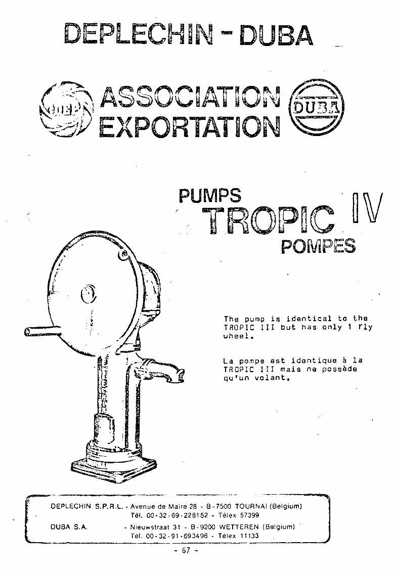
PUM asnm
The pump is identical to the TROPIC III but has only 1 fly wheel •
La po.-npe est identique a la TROPIC III mais na poss&de qu'un volant.
DEPLECHIN S.P.R.L. - Avenue de Maire 28 - B-7500 TOURNAI (Belgium) Tel. 00-32-69-228152 - Telex 57399
DU8A S.A. Nieuwstraat 31 - B-9200 WETTEREN (Belgium) Tel. 00-32-91-693496 - Telex 11133
- 67 -- /

The mecanism is identical to the TRGPIC III, but free delivery, no possibility of pumping against a positive head.
La mecanisme est identique a celui de la TROPIC III, mais d^versamsnt au sol, sans possibility da refoulement en hauteur.
^ DEPLECHIN S.P.R.L - Avenue de Maire 28 - 8-7500 TOURNAI (Belgium)
Tel. 00-32-69-228152 - Telex 57399
DUBA S.A. Nieuwstraat 31 - B-9200 WETTEREN (Belgium) Tel. 00-32-91-693496 - Telex 11133
- 68 -

v. fQ /
PUMPS
•Th8 pump is identical to the TROPIC VII but has only 1 fly uheal
La pompe est identique a la TROPIC VII mais ne posseda qu'un volant.
DEPLECHIN S.P.R.L. - Avenue tie Maire 28 - B-7500 TOURNAI (Belgium) Tel. 00-32-69-228152 - Telex 57399
DUBA S.A. - Nieuwstraat 31 - B-9200 WETTEREN (Belgium) Tel. 00-32-91-693496 - Telex 11133
- 69 -

• i h l ri
I
V
ffc w
u
VD " ^
DEPLECHIN S.P.R.L. - Avenue de Maire 28 - B-7500 TOURNAI (Belgium) Tel. 00-32-69-228152 - Telex 57399
DUBA S.A. - Nieuwstraat 31 - B-9200 WETTEREN (Belgium) Tel. 00-32-91-693496 - Telex 11133
- 70 -

0 cyl. mm
Debit capacity *
50
720
60
1050
70
1420
80
1850
90
2350
100
2900 •
* a 40 cps/min. Rendement hydraulique : 0,85
M. 1 - X l l ' U I M UI.MD.J— J-.'.l„.i»»M[ynMk..J.ail i.mfcMPi.ifmi.1,1111 | L , , , „

PUMPS
Brand
MGrque
Fabrikat
Manufacturer
Producteur
Hersteller
Operation
Manipulation
Bedienung
Pumping method
Methode de pomper
Pumpenmethode
Specification
Specification
Spezifizierung
POMPES PUMPEN
\3\JU W 11
H . J . Godwin Ltd
Quenington , C i r e n c e s t e r
G l o u c e s t e r s h i r e GL 7 5 B f
ENGLAND
Hand d r i v e n f l y v/heels pumps
and Pumps wi th a hand le
Porapes a v o l a n t s
e t Porapes a l ' a i d e d ' u n b r a s
Handpumpen mit Schwungrad od. mit Hebel
•
Pump rod, Pump cy l inder and Pis ton
Tige de commande et P i s ton
Kolbenstange und Kolbenpumpe
Deep well pump
Ext rac tab le or non-ex t rac tab le Cylinders
- 72 -

GODWIN WIH5I PUMP
t
t)
L—190 1 -190-o
-230-
ISO
I i '
Li !
&
i l l
Rising T O O 2 2 3SP
/^STN $
73 - .fcrt=y

Pumpstand (handle not fitted;
GODWIN WIH5I PUMP
if
Dismantled pump cylinder
'~^£g&^^ •a.*v ^ ^
- 74 -

GODWIN HMA POSITIVE DISPLACEMENT HAND
OPERATED COMMUNITY BOREHOLE
RECIPROCATING PISTON PUMPS
The new range of HMA hand operated pumps has been designed within the latest guidelines published by World Authorities on Hand Pumps and Hand Pump Maintenance and is backed by Godwin's own 55 years experience in the hand pump field.
Maximum emphasis has been placed on reliability and minimal maintenance and the inbuilt high mechanical advantage of the HMA range provides one man operation to depths down to 250ft. With two man operation the maximum depth is 400 ft.
A complete installation comprises an operating head at ground level coupled through rising main pipe and pump rodding to a cylinder down the well with footvalve and suction pipe. A wide range of cylinder sizes is available, both non-extractable and extractable, providing a capacity range from 55 gallons per hour up to 460 gallons per hour at 45 strokes per minute. Being a positive displacement pump, the achieved output is directly proportionate to the number of strokes per minute.
The pump is normally supplied for Lift duty only, i.e. delivery at spout, but it can easily be converted to Lift and Force by connecting direct to the spout or by removing the spout and connecting direct to the operating head.
Maintenance, being minimal, is normally restricted to occasional adjustment of the operating head gland and this only on Lift and-Force applications. Double sealed for life bearings with dust shields ensure the exclusion of dust and the elimination of all greasing and oiling arrangements.
- 75 -

OPERATING HEAD in heavy section Cast Iron with rotating parts of forged steal. Pump rod in ground EN3 steel. Rotating bearings grease packed and sealed for life. Pump rod slide bearing of oil filled bronze having removable adjustable coloured shims to take up wear.
FLYWHEEL constructed in steel with counterbalance weights adjustable both in size and position to ensure a smooth reciprocating cycle and minimum operating effort.
Galvanised r i s ing main pipe to B.S. 1387 (para l le l thread)
Galvanised s teel or wooden pump rodding.
Ball valve cylinder constructed in gunmetal and brass with double dressed sealing leathers and stainless steel non return ball. Extractable or non-extractable types.
Galvanised suction pipe to B.S. 1387.
Footvalve and strainer constructed in brass with stainless steel spring.
- 76 -

PERFORMANCE TABLES
(4" Stroke/Non-Extractable Cylinder)
Type
ZN1 ZN2 ZN3 ZN4
Cylinder Size (ins)
2" 2i" 3" 4 "
Output at 45 Strokes/ Mm. G.P.H.
115 180 260 460
Maximum Head 1 Man
Metres
30m 22m 16m 12m
Feet
100' 70' 50' 40'
Maximum Head
2 M
Metres
60m 44 m 32m 24m
en
Feet
200' 140' 100' 80'
Rising Main
Dia (ins)
H " 11"
1 1 " 2"
Suction Pipe
Dia (ins)
H " 1 1 " 11 " 2"
Min. Bore Hole Dia
(ins)
2 1 " 3" 3J" 4J"
(4" Stroke/Extractable Cylinder)
Z1 Z2 Z3 Z4
2 1 " 2 1 " 3 1 " 3 1 "
150 210 300 410
24m 18m 14m 12m
80' 60' 45' 40'
48m 36m 28m 24m
160' 120' 90' 80'
2i" 3" 4" 4 "
11 " 11 " 2" 2"
3J" 4 1 " 5" 5 1 "
(2" Stroke/Non-Extractable Cylinder)
(2" Stroke/Extractable Cylinder)
YN1 YN2 YN3 YN4
2" 2 1 " 3" 4"
55 90 130 230
55m 37m 28m 18m
180' 120' 90' 60'
1.10m 74m 56m 36m
360' 240' 180' 120'
1 1 " H " 1 1 " 2"
H " H " 11" 2"
2 1 " 3" 3 1 " 4J"
Y1 Y2 Y3 Y4
2 1 " 2 | " 3 1 " 3 | "
75 110 150 205
73m 43m 30m 20m
240' 140' 100' 65'
120rn 86m 60m 40m
400' 280' 200' 130'
2i" 3" 4" 4 "
H " H " 2" 2"
3 1 " 4 1 " 5" 5 1 " '
g#dwin pumps G ',^es ,e ,;">••€ G<-? 58x E n g ^ d Te ecr.o-e Co : 'S i A:a*,r-s, ;028 575) 2?1 Tee» 432-iO Cac es Pumps C^en
Produced by D. J. Livingston & Associates Limited Printed in England „ 77 ,

- * - » . • •> . : • ** " • -» 9f,
V> I
*.,::
i^>-
^C*.
m u Mm
Heavy pattern low cost lift and force hand pumps for wells and boreholes not exceeding 27 ft. in depth. Outputs range up to 760 g.p.h.
S P E C I A L F E A T U RES
B Dual purpose operation - can be supplied for lift only or lift and force.
B All steel construction for extra rigidity and long life under arduous conditions.
• Pump is fitted with sanitary type base.
Q Low cost.
H.J.GODWIN LTD 78

GODWIN SERIES HLS PUMPS RANGE Three sizes are available with cylinders of 3". 3 } " and 4".
APPLICATIONS Domestic use in isolated farms, cottages etc.
SPECIFICATION STANDARD Fabricated steel fitted with working cylinder of solid drawn brass tube. A delivery boss is provided when the pump is required for lift and force duty.
HANDLE Round section, smooth steel with hardened steel link pins - easy to operate.
SPOUT Steel, straight through delivery. For lift and force duty, the spout is cast iron fitted with a non-sticking draw-off cock.
BASE Heavy cast iron, easily adjustable sanitary type, simply fixed over borehole or on bearers over well. Screwed to suit rising main pipes.
.AND Easily adjustable gunmetal screw type fitted on all pumps for lift and force duty. For lift only a brass guide is fined.
SUCTION VALVE Weighted flat type, working on gunmetal seating.
BUCKET All gunmetal with best quality hydraulic cup leather. Will not rust or corrode.
SUCTION PIPE Galvanised steel; size according to pump required.
FOOTVALVE The high efficiency Godwin 'B' type, a stainless steel ball working on gunmetal seating.
FIN ISH Attractive weather-resisting paint.
DIMENSIONS
PUMP ROD-
GLAND SCREW TYPE-
SPOUT WITH
NON-STICKING
DRAW-OFF COCK-^^
DELIVERY BOSS
I f B.S.P. THD
ALL STEEL STANDARD-
HEAVY SANITARY BASE-
, rVrV*
V I 4 8i
..•t I I 25
U — SUCTION PIPE
SERIES HLS FOR LIFT AND FORCE
GUIDE
-HANDLE
-SPOUT (PLAIN)
,h=^, GROUND LEVEL
TF -SUCTION PIPE
SERIES HLS FOR LIFT ONLY
-+-^Sf.
7W 7;-9" BASE FIXING PLAN
OUTPUT RATINGS
Type
HLS 3 HLS 3J HLS 4
Bore of Cylinder
(in.)
3 31 4
Output ( Im serial g.p.h.J* Strokes per min. 30 40
315 435 570
420 580 760
Dia. Suction Pipe 3.S P. (in.)
11 2 2
Delivery Boss B.S.P. (in.)
11 11 11
Length o( Stroke (in.)
Outputs are calculated on a 7" work ing stroke.
SPECIFICATIONS and ILLUSTRATIONS are subject to revision without notice.
H. J. GODWIN LIMITED QUENINGTON • GLOUCESTERSHIRE • ENGLAND
7 9 - Teiep^cr.e Coin St A!dA>ns 271 (6 lines) Teiegran-.s "Pumps Q u e n i n g t c r " Telex 43240
( „W/o» Ul C 7

•huLW—-atVJig*
f' 1
•nli i iMJV- M \ U l. 1 in
M l . i' MMJ
t j ! : ! : ! i • !. i i ; ; '.'J
Ft I Ujywyy Ik
T^SJf"»J f * - "A " ."' '*•• L t ~ * * * '
Vrt &£/ f ->>
'j a o n D
i r ' n i a m ii —
Heavy pattern low cost lift and force hand pumps for wells and boreholes exceeding 25 ft. in depth. Extractable or non-extractable cylinder types are available. The former allows withdrawal of the cylinder bucket without disturbing pipework; non-extractable cylinders mean smaller rising main pipes and therefore lower installation costs. Outputs range up to 660 g.p.h.
S P E C I A L F E A T U R E S H Dual purpose operation - can be supplied for lift only or lift and force.
• All steel construction for extra rigidity and long life under arduous conditions.
E Pump is fitted with sanitary type base.
EJ Low cost.
H.J.GODWIN LTD - 80

GODWIN SERIES HLD PUMPS R A N G E
Extractable cyl inder pumps are available w i t h cylinder sizes of 2 J " , 23 " . 3 1 " and 33* . Non-extractable cylinder types have cyl inder sizes of 2 ' . 2 J ' . 3 " and 3 1 " .
A P P L I C A T I O N S
Domestic use in farms, cottages etc.
S P E C I F I C A T I O N S T A N D A R D
Fabricated steel, making it virtually unbreakable. Spout connect ion and delivery boss for lift and force is welded on, screwed 1 1 " B.S.P. thread.
H A N D L E
Round section, steel link pins -
smooth steel w i t h hardened easy to operate.
S P O U T
Steel, straight through delivery. For lift and force duty, the spout is cast iron f i t ted w i t h a ion-s t ick ing draw-of f cock. When c losed, the delivery is taken off the boss provided in the standard.
B A S E
Heavy cast i ron, easily adjustable sanitary type, simply fixed over borehole or on bearers over we l l . Screwed to suit rising main pipes.
G L A N D
Easily adjustable gunmetal screw type f i t ted on all pumps for lift and force duty. For lift only a brass guide is f i t ted.
R I S I N G M A I N P I P E S
Galvanised steel, approximately J ' larger in the bore than the cylinder (extractable type) . For non-extractable cylinders, the rising main pipe is approximately half the size of the cylinder.
P U M P R O D S
For extractable cylinders, these are of specially selected p inewood fi t ted w i t h steel fork ends and strap coupl ings; alternatively •jalvarvsed steel rods w i th hexagonal coupl ings. Steel rods are always used w i t h non -extractable cylinders.
C Y L I N D E R S
Extractable spear or non-extractable ball valve type. Constructed almost completely of brass and gunmetal , w i t h best quali ty hydraul ic cup leathers.
S U C T I O N P I P E
Galvanised steel threaded to take footvalve.
F O O T V A L V E
The high eff iciency Godwin 'B ' type, a stainless steel ball work ing on gunmeta l seating.
F I N I S H
Attr". : t ive weather-resist ing paint.
DIMENSIONS
4 8 !
F IGURE 1
GLAND
i — H A N D L E
SPOUT WITH DRAW-OFF COCK
ALL STEEL STANDARD
DELIVERY TAPPED
1j" B.S.P. THD.
4;"T GROUND LEVEL
^ FIGURE 2
<&T -SPOUT
±L TEE-PIECE BELOW GROUND DELIVERY
W O O D RODS
RISING MAIN
EXTRACTABLE CYLINDER
4 HOLES F O R ) ' DIA. BOLTS
9 '
— RISING MAIN
;—STEEL RODS
F L NON-EXTRACTABLE CYLINDER
- F O O T V A L V E
7,'
3 9' FOOTVALVE
BASE PLAN
Figure 1 shows pum p arranged for lift and force duty.
Figure 2 shows pum p as standard for lift only.
INSTALLATION DATA
Max. Base Screwing
4 ' B.S.P.
Delivery Screwed
1 J ' B . S . P .
Stroke Length
7 "
Pump Rod Screwed
J " Whit. Thread
When delivery is taken off below ground level a tee piece (supplied as an extra) must be fitted in the rising rna'd pipe.
OUTPUT RATINGS Extractable Cylinders
Type
HLD 2 i
HLD 23
HLD 31
HLD 33
Cylinder Size (in.)
21
23
31
33
Outputs (Imperial g p h . ) * Strokes per mm.
20 30 40
120 180 240
180 270 360
250 375 500
330 495 660
Dia. Suction Pipe B.S.P. (in.)
U 11
11
11
Dia. Rising Main B.S.P (in.)
21
3
31
4
Min. Ota. Bore (in.)
33
41
5
51
Non-Extractable Cylinders
Type
HLD 2
HLD 21
HLD 3
HLD 3 j
Cylinder Size (in.)
2
21
3
31
Outputs (Imperial g.p.h.)' Strokes per mm.
20 30 40
90 135 180
145 220 290
210 315 420
290 435 580
Dia. Suction Pipe B.S.P. (in.)
U 1 i
11
2
Dia. Rising Main B.S.P. (in.)
11
11
11
2
Min. Dia. Bore (in.)
21
3
33
41
"Outputs are CALCULATED on a 7" working stroke MAXIMUM strokes per m.nute with power drive is 45.
SPECIFIC A TIONS and ILL US IRA TIONS are subject to revision without notice.
81 H.J.GODWIN LIMITED QUENINGTON • GLOUCESTERSHIRE • ENGLAND Telephone Co!"- Sf A:c.v>ns 27 1 ,6 Lews* Tc'tg-'J^s "Pjrr.ps C j e i > ; : - r V Telex. 432-1Q
AACC ncntio nc rr\KAPn MIF ^

PUMPS
Brand
Marque
Fabrikat
Manufacturer
Producteur
Hersteller
Operat ion
Manipulation
Bedienung
Pumpinci method
Methode de porriper
Pumpenmethode
Specification
Specification
Spezif izierung
POMPES PUMPEN
Mono Pumps ( E n g i n e e r i n g ) Ltd Mono House
Sekforde S t r e e t
C l e rkenwe l l Green London EC 1 R OHE ENGLAND
Rotary pump wi th two h a n d l e s
a l ' a i d e de deux b ras ( r o t a t i o n )
mit zwei Drehhebeln
D o u b l e - h e l i c a l r o t o r i n s i d e a t r i p l e -h e l i c a l r u b b e r s t a t o r ( screw p r i n c i p l e ) ( p r o g r e s s i v e c a v i t y pump)
Mono pompe ( p r i n c i p e de h e l i c e )
Fumpe mi t Rotor und S t a t o r ( F r i n z i p d e r Schraube)
Deep w e l l pump •
- 82 -

r—r
6 is
"T 90
_ 1 _
»5CO
Risng main 17 9SP
MONO ES 30 PUMP
- 83 -

MONO ES 30 PUMP
Pumpstand (one handle not fitted)
* - i n r — * - " - '.Trtiiiii*
Dismantled pumping element
/.< KrT,
:^
- 84 -

MONO ES30 PUMP
Dismantled gearbox
"•?-.• N
'\\&Z?*~r<i$l
>». « i . r v ^ ,> Zk
# ; / HJ (U U -^
W
>f& <•}• ^ >
- ^ ' . v * j < a s « r r « 3 ; ^Si":^*."-***-'
- 85 -

PUMPS
Brand
Marque
Fabrikat
Manufacturer
Producteur
Hersteller
Operat ion
Manipulation
Bedienung
Pumping method
Methode de pomper
Pumpenmethode
Specification
Specification
Spezif izierung
POMPES PUMPEN
m IftlAV
Barnaby Climax Ltd
White Lad ie s Close
L i t t l e London
Worces t e r , WR 1 1 PZ ENGLAND
Hand d r i v e n f l y wheel pump
Pompe a v o l a n t
Handpumpe mi t Schwungrad
Crank s h a f t , P i s t o n rod and P i s t o n
Arbre coude , Tige de commande e t P i s t o n
K u r b e l w e l l e , Kolbens tange und Kolbenpumpe
Deep w e l l pump
- 86 -

1056 CLIMAX PUMP
Sfcsmg mem 2 ? BSP
- 87 -

CLIMAX PUMP
Pumpstand (handle not fitted}
Dismantled pump cylinder
;f
:e sf'
* ' - . I » I ,
4. » •
- 88 -

PUMPS
Brand
Marque
Fabrikat
Manufacturer
Producteur
Herstel ler
Operat ion
POMPES PUMPEN
A C D I P A D A V A I r- ^ A - S
B r i a u S.A.
B.P. 0903
37009 Tours Cedex
FRANCE
Hand d r i v e n f l y wheels pumps
and Pumps w i t h a handle
Manipulation
Bedienung
Pompes a volants
et Pompes a l'aide d'un bras
Handpumpen mit Schwungrad od. mit Hebel
Pumping method Fump rod, Pump cylinder and Piston
Methode de pomper T i g e d e commande et Piston
Pumpenmethode Kolbenstange mit Kolbenpumpe
Specification Deep well pumps
Specification
Spezif izierung
89 -

Pompe AFRICA pour pompage manuel, a moteur, par traction animale
BRIAUSA
POMPAGE MANUEL
POMPAGE A MOTEUR
<7
Mi
POMPAGE PAR TRACTION ANIMALE
La pompe Africa est une pompe a commande par volant, extremement robuste. Son util isation depuis plusieurs dizaines d'annees dans certains pays d 'Afr i -que, a prouve sa tres grande fiabilite. Elle permet d'obtenir des debits importants sous de grandes pro-fondeurs.
Ses caracteristiques sont :
• Puisage jusqu'a 1 00 m de profondeur.
• Refoulement jusqu'a 70 m au dessus du sol.
• Debit instantane de 3 0 0 a 5 .000 l/h.
• Construct ion mecanique tres soignee et particulie-rement robuste, capotee sous une gaine en forte tole d'acier.
• Installation simple et rapide a partir du sol, sur un puits ou un forage meme tres etroit.
• Elements standards rigoureusement interchan-geables.
• Volants equilibres en acier pouvant etre entralnes indifferemment dans les deux sens.
• Rendement eleve obtenu par equilibrage statique et dynamique de I'ensemble.
• Entretien pratiquement nul, avec reserve impor-tante d'hui le de graissage et paliers auto-lubrif iants.
• Organes prevus pour resister a I'abrasion du sable contenu dans I'eau pompee.
Le mecanisme comporte une commande directe et une commande demultipliee dont la combinaison, avec les 3 courses de la bielle, offre 6 possibiiites de reglage par corps de pompe. Cette disposition permet ('adaptation facile de la pompe aux differentes pro-fondeurs.
- courses de la bielle : 100, 140 , 180 mm. - Rapport de demultiplication : 1/3,2 - Progression des cylindrees : 1 - 1 , 4 - 1 , 8
3,2 - 4 , 5 - 5,7
L'adaptation de deux corps de pompe de diametre 60 ou 1 20 assure une gamme tres etendue des possibiiites de la pompe.
Bf i lAU SA T
90 -

Pcmpe AFRICA pour pompage manuel, a mcteur, par traction animale
BRiAUsA,
M A R C H E A B R A S
i*Z><*
K ? \ r > ;••.-.•••
>••••:• •-• * ^ • • • ^ • • " R H E U E , . ^ - : - j v ^
I ! I j
PISTOL SO PISTON 0 120 PISTON 0 120
iOO i t * ! 180 I
CCMUANDE Cirecie
ENTRAPMENT a 45 t.;mn
Le pompage a bras est possible jusqu'a 5 0 m de profondeur en exercant un effor maximum de 1 5 kg sur la manivelle tournant a 4 5 t . /mn.
Plusieurs possibilities sor.t offertes :
- MARCHE A 1 MANIVELLE
1 manivelle sur commando directe 1 m3niveile sur
commande demultipli6e
Caracteristiques de pompage (voir diagramme)
- MARCHE A 2 MANIVELLES possible jusqu'a 5 0 m avec deux util isateurs : elle permet d'obtenir un debit plus important
Caracteristiques de pompage (voir diagramme)
COJnSt --.;TI •
M A R C H E A M O T E U R
Entrainement realise avec un moteur
T0UT£S PRGFCSDEURS JUSQU'A ICO M
& ^XI. ' .VT.. . _ .3Vi'.'" l^'^*** ' ~ V * - .M*^- rK--<r
_ ... .••'•-.r-.,'-v ^-•.•"^ ' ' • • • f c l . " ^ * •• •**' •••*.'-" i . .v. i » - (>..>;;
r -sO'TRES PAR NEURE. _\ij'v -j-Wv-'j
PRGfONGEURS LlMiTEES '• -'0
PISTON 3 50
i COURSE mm 1 i
; 100 UO 130
PISTON 3 120
COURSE mm I i
100 I ItO ' I8C
3CU' - C ^ . t V l it " ";.is«
MO
thermique ou electrique, sans modif ication du chasis. Pour le refoulement en pression et a longue distance, ou lorsque la profondeur du puits depasse 4 0 m, nous recom-mandons notre dispositif anti-belier.
:E5*S HCAA;S;S SO;VS»; COURS: t t : ou ?:s'on
M A R C H E PAR T R A C T I O N A N I M A L E
L'util isation des animaux comme moyen de tract ion a et6 appliqjee a la pompe AFRICA par I'adjonction d'un manege. La mise en place du manege s'effectue sur un chassis soiidaire a la pompe AFRICA. Le debrayage rapide permet le retour au pompage a bras. Un ou deux t imons reglsbies permettent I'entrainement du manege, consti tue par un dispositif multiclicateur enferme sous un carter en forte tele d'acier. Le meca-nisme est sureleve de 1 metre environ, afin de I'isoler du sol.
HAUTEURS MAIW3METRI0UES O'UTil.SATiON EN METRES
i ; i i : ; 100 80 6S «S )J 15 U
T : xo
\\IV-J:
1 750 f ./. 4-^ 4
: tOCp<r^{- f •/•;•.;.-i.v- ,
f ^ l LITRE ES PAR >••£!.•?•:£
COURSE mm
100 140 130
COURSE -™~. I
! I i !00 I l<0 ! i K
P:STC\'Z62 PiSTGMO 120
3 TOURS CE MANEGE par mn.
CARACTERISTIQUES GENERALES
DE LA POMPE AFRICA
rc6:r;3ue de la raHcrge 7,7 d'un corps fie ponpe avec ctepine 26
Pcids d'un '.a.-ncour c'entroinement 16 iu r.ancge a>ec socle e! !a Meche 430 du chassis con-.mun 100
Hauicur loiale . . . Hauteur ss-js :e jet . Diamiue d'un volant
kg P:ids lotal :e u pompe avec las 2 volants Pj.Js des 2 votanss . . . Po.Js Ces 2 -as;clo:!es
e.i kg
1.-35 i 0.535 0.800
370 8i
POMPE 1 caisw 1.5C « 1.15 • 0.50.T. . 370 1 fa.-deaude 2 volar.ts-diam. C.80 m : epais:eucCI.20 m 120
R A L L O N G E en lardeaci E:;:c-iis ie 3 T ? " ; S ,1L- 'o.- .^ur e«:.-?:r-::ss DIGTC-SCJ : r je u icile de j^te. cciienan! chacuc. 9 xetresoerallcnge C 50 " 6C. ei ' : :~o:eTitr i .TioyenO 12 rr ?0lCSKg 7C
MANEGE 1 tw ;e 1 10 • 0.30 - O.JC.ti 320 chaise - 1 tsrdss-j 1.30 « 1.40 • 0.21 m 75
Icrjeions - l l j tacaj 2.25 • 0.2C « C.21 m 9C
timon - 1 iuoe lorn,j5cr 3 m . . . 24
flacr.e d'a;:e!age - 1 lariea- Icrj. 3.20 m 20
COL.SAGE .MARITIME
Les d»T.e^sio,is et oo'is aes c j . i ses sor t donnSs
d ;ltre incicatif.
- 91 -

N E P T A P u m p s Cable operated hand dr iven pumps
pntonted models
NI-.P"! A C (classical)
BRIAUSA (X:
f'lHK'Htll
^
)
tfls ' & ? - * • , & *
Particularly robust and easy working pump, specially designed for arid areas.
• Pumping to 100m in depth
• Important deliveries
• Mount ing on wells, min imum diameter 4 "
• Self-priming w i th no previous filling needed
• Stainless cable operating wi th rigid exhaust tubing to make maintenance easier
• Upper mecamsm on waterproof bearing and safety housing
• Protection against introduct ion of foreign bodies
• Small overall dimensions and easy setting up
• Can be driven by an engine if wanted.
NEPTA D (detachable)
Piinciplu
. . . * • • ' * • w .
.(T) • Pu i ;p brad .HJt of Mronti plasti.'ied sheet (nisan)
(5) • Ooufili.' operating U.-vor wi th acl|ustahle length
(3) UnoM(li/,ible opeiating cable wi th linear niovt.-iiiont
(4) ('yli inli ' i and pis M M (with piston-rings) w i th 92 -
• 1 1 , ; . , . . f , , .c-r .
(5) - exhaust tubing
(6 ) • Dual strainer valve
(7) - Stainless tension spring
( D Prop block
(^\ Tmht base

Pompes NEPTA
rron^ps ^"^vp't's BRIAUSA <£
ues pompes NEPTA son: des pompes de longue duree, demandant un entretien minin ium.
Car.s la cof-coption tie cone pompe, il a ete tenu cor-pte du problsme du poids et de la resistance, c'est la raison pour laquelle le corps superieur est const rue p.-.* un tube rectangulaire en acier piastif ie, de forte epaisseur et de faible hauteur (80 cm environ!.
La pompe comporte une tete sous carter etanche a la part.'e supeneure du puits ; la manoeuvre s'effectue par baiancler en acier a longueur reglable. pour en faciiiter la manoeuvre, et oscillant sur un axe large-men: d!mens;onne, supporte par deux roulements etanches, ou palier lisse, sur demande.
Le prmcipe de fonctionnement est identique a celui d'une pompe a tringle classique : cylindre a piston a la base du pu;ts actionne depuis la partie superieure par un balancier.
La particularity de la pompe NEPTA reside dans sa simplicity, sa rcbustesse de construct ion et, plus par-ticul.erement. sa faciiite de montage.
• La commande du piston, place dans le cylindre infe-rieur, est realisee au moyen d'un cable inoxydable acticnne, depuis le sol, par un secteur semi-circulaire lui assurant un deplacement parfaitement rectil igne. • La tuyauterie de refoulement est normalement ccnstituee par un tube en acier galvanise ; cans la version D, elle comporte un revetement complemen-taire anti-corrosion ou peut etre Iivr6e en PVC sur demande.
• L'arfapfation d'un diametre de cylindre approprie' permet d'cbtenir le debit maximum possible. • Pcmpage jusqu'a 100 m de profondeur.
• La pompe NEPTA s'amorce automatiquement, sans remplissage preablable.
• La quaiite des materiaux utilises, en particulier dans la conception des pistons, assure un fonct ionnement de longue duree.
Le piston est du type seqmonte (brevete*. evitant les f rot tements, ot I'usure de la garniture h.aq:t;:e:!e en cuir, ainsi que du cylindre. Les segments sont cors t i -tues par une tresse speaale livree en couronne. qui permet le 'emplacement eventuel, sans diff iculte. des garnitures en place. Los ossais, ce longue duree. cnt montre que la iongevite de ce piston segmente est d 'environ dix fois ceile du piston traditionne! en cuir et son rendement sensiblement superieur, ce qui permet I'utilisation de la NEPTA pour des profondeurs et debits importants.
Pour les regions a altitudes elevees, avec risque de gel, cette pompe peut etre equipee d'un dispositif antigel automatique.
Les pompes NEPTA peuvent recevoir au montage, ou ulteneurement, une motorisation par moteur thermi-que facilement adaptable, ainsi qu'un manege pour la t ract ion animale et eventuellement une crepine speciale antisable.
Differents modeles
• NEPTA C (classique) pour pompage jusqu'a 100 m. La tuyauterie de refoulement, en acier galvanise, est d 'un diametre adapre au debit pompe.
• NEPTA D (demontable) pour pompage jusqu'a 1 0 0 m.. La tuyauterie est d 'un diametre superieur a celui du cylindre. ce qui permet la remontee du piston sans demontage de la tuyauterie. Cette manoeuvre de demontage et remontage du piston-s'effectue rapice-ment par la main-d'eeuvre locale, sans outillage special, ce qui diminue considerablement le cout de I 'entretien. La tuyauterie de refoulement est normalement en acier galvanise, avec revetement comple-mentaire de protection anti-corrosion ; en opt ion, cette tuyauterie peut etre fournie en PVC.
CARACTERiSTIQUES TECHNIQUES Profondeur maxi en metres
Debit l/h a 4 0 coups/mn
•5 0 nominal mm f. 0 exterieur mm
s
' i
1 NEPTA C
1 NEPTA D 3
0 ex:, du manchon
Pcids approxirnatif ernballe
10
4 5 0 0
120
135
50
consi
Tete * C fardaau d
15
3000
25 45
J 2000 1200
100 ! 80
115J 95
50 40
| 95 j l ter '
I ,09
ylir.dre + asp;ratio e 4 cubes de 3 roe
60
78
33
66
82
n. enviror '.res
• 65
800
50
78
33
66
82
- 7 - 4
100
4 5 0
4 0
78
33
50
65
]k5
5 kg
BRIAUSA' - 93

J
^ - . ^
One of the mnny models which has built ORIAU's reputation, the ROYALE Pump can be counted on for its sturdiness.
Its main feature? are the following :
. Pumping to depths of 65 m,
. Possible lift up to 7 meters above surface,
. Self priming,
. Lift output at the spout or under surface,
. Rod operated,
. Piston in Bronze - Cylinder in brass,
« . Sand t ight seat,
. High f l e x i b i l i t y : - 3 p is ton strokes (150, 200, 250 mnt) - 4 cylinder diameters (50, 60, 80, 100 mm)
. Counterweight balancing on operat ing lever .
S P E C I F I C A T I O N S
J Cylinder mm External 0 mm •
Stroke mm
Output (liters/h)
Total Head 'meters)
Ralancinq counterweights of ]kq
100 115
250 200 150
3530 2825 2125
9 12 15
.80 95
250 200 150
2250 1800 1350
15 19' 25
1
60 78
250 200
1270 1020
26 ' 33
. 3
150
750
45
250
800
38
i
I
50 78
200
700
48
5
150
5"? 5
65
orr-iFNisroNS .-
Total height '<•<:• : :bA f r.v:i -.pi-l.it
i-1 '.-. ii; t i o n p i t v
t-i lift pipe •Fixing riiinpnri ions
n
1,70 m 0.A5 m
50 X Ml mm 40 X 49 mm 250 X 250 mm
-94 - i (X;
Net weight Volume (packed)
78 kg : 0,3 n>3
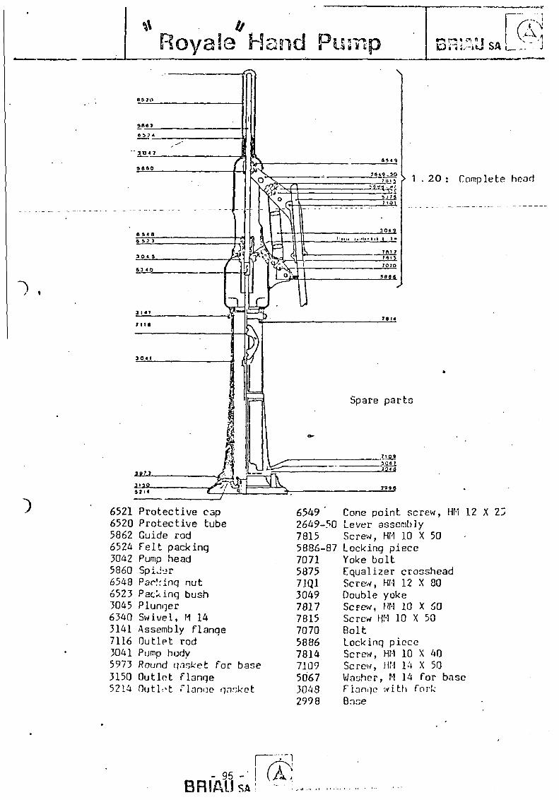
Royaie Hand Pump t 3 i ; ; . - i J SA
^~*, i
(20
1 . 2 0 : Complete head
Spare p a r t s
6521 6520 5862 6524 3042 5860 6548 6523 3045 6340 3141 7116 3041 5973 3150 5214
P r o t e c t i v e cap P r o t e c t i v e tube Guide rod F e l t pack ing Pump head Sp iJu r Pac.'rinq nu t Pack ing bush P lunger S w i v e l , M 14 Assembly f l a n g e O u t l e t rod Pump body Round gasket f o r base O u t l e t f l a n g e O u t l e t f i a n c e gasket
6549 2649-7815 5886-7071 5875 71Q1 3049 7817 7815 7070 5886 7814 7109 5067 3048 2998
50
87
Cone p o i n t screw, HM 12 X 2Z Lever assembly Screw, HM 10 X 50 Lock ing p iece Yoke b o l t Equa l i ze r crosshead Screw, HM 12 X 80 Double yoke ScFew, HM 10 X 60 Screw HM 10 X 50 Bolt Lock ing p iece Screw, HM 10 X 40 Screw, HM 14 X 50 Washer, M 14 f o r base Fiangi? w i t h fo rk Bnse
r; BRIAUSA
« * . A

Pompe T R A C T A Pompe a commande manuel le a ac t i on d i rec te
modelo breveti
(A) BRIAU«_.
Puncoe
....$
C'\
^v-.
Pompe ent i t lement protegee contre la corrosion particulierement robuste con-cue pour les puits de faible profondeur
• Pompage a action directe
• Debit : 1 0 0 0 a 1 2 0 0 l/heure
• Profondeur jusqu'a 1 5 m
• Forage minimum 2 1 / 2 "
• Mise en place tres rapide
• Auto-amorcage sans remplissage preamble
• Mecanisme indestructible (sans vis. ni axe apparenrs)
• Protection contre I ' introduction de corps etrangers
• Pompage facile pour un enfant
• Debit obtenu meme avec une faible amplitude
• Garantie de longue duree
CONSTRUCTION
- Tete de pompe en acier plastifie (Rilsan) avec tige de commande en acier inoxydabie (18.10). Cylindre de pompage incorpore a la tuya'uterie de 2", pe.'ir.etiar.t eventuellement I 'enfoncement direct par percussion dans le sol sans forage
- Piston segmente brevete limitant I 'effort et d'une dur6e d'ut i l isat ion dix fois superieure aux pistons traditionnels
- Remontee rapide du piston sans demontage de la tuyauterie - Tringlene rigide et equilibree ameliorant le rendement de la pompe
- Options pour : eaux chargees,crepme enveloppante PVC longueur 2 metres enfoncement par percussion,tuyauter ie(?) galvanisee 2 "
0-
Qj - Tete de pompe en forte tole plastifiee
© - Tige de commande inoxydable 18.10
( i ) - Ressort de compensation inox
Ci) - Tringlene PVC equilibree
{^) • Tuy3u:ene de refoulement
(*J - Cylindre a piston segmente
Qj • Double clapet crepme OpTOn 4*eC PO'«Tf C '«D ' n * t
par pe'CwSS-o"
&
, ' - • • • »•- hi
C- '•••.J.'-
:&i
r:-'
"«Tfr.
JLl
O
o"
. O .
© ; • > . "
;*".'
" . ' < •
i v>
<D
- 96 -SRIAUSA
ffi I 8 P C903 3'OOS rOvflSCiSc* fRA-.cs T£.i x /so ; .••*; : E W - ' O '

Pompe T R A C T A P o m p e a c o m m a n d e m a n u e l l e a a c t i o n d i r e c t e
modele b'evexi BRIAUSA
Sp£cialement concue pour les nappes a faib'e profondeur, maximum 1 5 m., cette pompe particulierement robuste compone un corps superieur cylindrique en forte tole plastifiee, ainsi qu'une commande par poignee agissant directement sur le cylindre.
Le cylindre de pompage est d'un diametre inferieur a celui de la tuyauterie, ce qui permet son montage et sa remontee eventuelle sans demonter la tuyauterie, ni la partie superieure de la pompe.
Le piston est du type segmente (brevete), evitant les frot tements et I'usure de la garniture habitueMe en cuir, ainsi que du cylindre. Les segments sont constitues par une tresse speciale livree en couronne, qui permet le remplacemer.t £ventuel, sans di f f icul t^, des garnitures en place. Les essais, de longue duree, ont montre que la longevite de ce piston a segments est d'environ dix fois celle du piston traditionnel en cuir et son rende-ment est sensiblement superieur.
La commande du piston s'effectue, depuis le sol, par une tringle en PVC concue de telle sorte que les efforts de mon:6e et de descente soient sensiblement equilibres.
Par aiileurs, la tige de commande superieure est const i tu te par un tube en acier inox 18 .10 coulissant dans un palier tres largement dimensionne et autolubrifie par I'eau pompee et, de ce fait, pratiquement inusable.
A i'inteVieur du corps de pompe superieur est place un ressort inox destine a favoriser la manoeuvre par de jeunes enfants qui , par de courtes impulsions sur la poignee superieure, peuvent realiser le pompage de I'eau.
Le mecanisme ainsi concu est pratiquement indestructible et la pompe presente une garantie de longue duree.
En option :
La TRACTA standard est normalement protegee contre la corrosion grace a son corps plastiffe, sa tringlerie en PVC et sa tuyauterie de refoulement en acier galvanise. Pour les eaux tres agressives, il est possible de fournir la tuyauterie de refoulement en acier galvanise revetu d'une protection complementaire anti-corrosion ou en PVC.
La Pompe TRACTA peut etre Iivr6e avec une pointe inferieure speciale, avec crepine incorporee, permettant i 'enfoncement par percussion, systeme particulierement avantageux, surtout dans les terrains alluvionnai-res, car on evite ainsi les frais eleves de forage.
Pour les eaux tres chargees en sable ou, lorsque apres installation de la pompe on remplit le trou pratique pour 1'installation, il est possible de livrer une crepine speciale de grande longueur Evitant tout colmatage eventuel.
Caracteristiques techniques : profondeur jusqu'a 1 5 m debit : 1 0 0 0 a 1200 l/heure
Pour profondeur superieure jusqu'a 4 0 m, nous consulter,
Colisage : Poids approximatif : 0,1 5 t - Volume moyen : 0,1 5 m3.
- 97 -
BRIAUSA 0303 37009 TCUKS CE06* USANCE • "6LEX 750 7 : 9F • TEL. : (47l 61 38 1 7

PUMPS POMPES PUMPEN
"•" « • B OIIR fi A Fabrikat
y V "^kM* * V
Manufacturer P e r e B o u r r i e r G a b r i e l
Producteur f a b r i q u e au MALI
Hersfeller
Operat ion Hand d r i v e n f l y wheel pumps
and Pumps w i t h a handle
Manipulation Pompes a v o l a n t s
e t Pompes a l ' a i d e d ' u n b r a s
Bedienung Handpumpen mit Schwungrad od. mit Hebel
Pumping method
Methode de pomper
Pumpenmethode
Specification
Specification
Spezif izierung
Pump r o d , Pump c y l i n d e r and P i s t o n
Tige de commande e t F i s t o n
Kolbens tange und Kolbenpumpe
Deep w e l l pumps
- 98 -

L.5-2 ZJUiJLSJL IUU.L2J. • -6. Mai 1981
BOURGA (-Pore HOURRIER Gabriel) •' fabrique au MALI, dapuio quatre ana doo pompeo manuolloa a pin ton iinniorge>
t commando* pur trln#lao****
I I propose I Una POMPS A BRAS*
LA BOURGA SIMPLEX, pompe r o t a t i v e - a l t e r n a t i v e a un volant*
LA BOURGA SUPER, pompe a deux volants qui do i t 6*tre aotioruvSe par deux adultoa ou quatre enfants*
LA BOURGA MAXI, pompo a deux volanta qui do i t o*tro actionne*© par quatro adult eo •
IA BOURGATiDEALE: Bourga oupor avoo un reduotour*
LA BOURGA GENIALE: Bourga super avoo un mot our. Dona lo cas da nor ,' fonotionnomont du motcnr, e l l o peut Stre aotionne'e par 2 peraonnes
LA BOURGA MOTOR* Bourga maxi aveo un moteur* Ello ne pout S t re act ionize mamiQllomont.Elle ost de preference plao^e sur un pui ts*
2° Or ig ina l i ty doa pompoa Bourga*
El lea son* simploa ot robustos*
El los aont prevucs pour un usage intonoif*
Lcs mate'riaux employes ( c l a p c t s . , * ) ont ate" ohoisis parnd. los mei Hours*
Leur oontropoids oaloule" double l a puisoance do V u t i l i s a t c u r ot annulo lo poid t r inglage*
E l l a s sont fabriqu^oa au Mali ot donnont aat isfaot ion*
r 3°.C.araoTt€ri3tiquoa et porformances*
1) La POMPE A BRAS. * • • • • I I I • • I • • • I I ^ I H l I •
o « i 3 a s s a a a s ] « a s E c a i
Ello oat prdvuo pour Stro actionneo par un adul to , raais doux onfanto pouvont pompor cftto a o$tc*
Crochot do t r ing lo ot pivot du braa oomportont dea roulcmenta a b i l l e a _J 6tanohoa graissd3 au lithium*
Lo pis ton a uno oouroo do 120mm* i La longuour du bra3 os t do 70 cm*
. Jusqu fa 12m, o l io roooit un p is ton do f$ 120 qui donno 2900 %/h Do 12 a 18m, un piaton do 0 100 qui donno 2000 l i t ros /houro* Do 18 a 24m, un piston do tf 90 qui donno 1600 l / h . Do 24 a 30m, un pi3ton do $ 80 qui donno 1250 y h * De 30 a 36m, un pi3ton do ^ 70 qui donno 9*50 1/0*.
Co» ddbits aont re'ola* l i s sont infeVioura do plua do 20jt par rapport au de"bit the'oriquo* I l a sont caloulej sur l a baso de 45 ooup3 do p i s ton / minuto.
2) LA BOURGA SIMPLEX*
El le est prevuo pour &*trc aotionnec par un adu l t e , maia doux onfants pouvent porapor faoo a faoe.
Le meoaniamo ost r o t a t i f - a l t c r n a t i f , a quatro tomps, avoo axes sur roulemonto a b i l l o s , c t cour30 du p i s ton do 120 mm*
Un grand volant regu la r i so lo mouvomont du piston* Un oontropoida ca lou lc , place* 3ur lo balanoicr annulo lo poida do3
tringloao-fr doublo l a pui3oanoo do l ' u t i l i o a t o u r *

I l i a eat agreablo a manoouvror. So* porformanoea sont ouperioures a l a pompo a bras* Juaqu'a 15motroo, o l i o roooit un pioton-do rf 120 qui donna 2900 l/h, Do 15 a 21m, un piston do ft 100 qui donno 2000 l / n . Do 21 a 27m, un piston do <foo qui donno 1600 l A » . Da 27 a 33fflf un pioton do <fi 80 qui donne 1250 ]J^. De> 33 a 45m, un piston do $ 70 qui donno 950 1/n.
''•"." 3) IA BOTROA SUFE3. ' • — m i l mri mua^trttiTm
Ello bat prevub pour fitro evotionndo par deux adultee t male quatre . enfante pouvent_poropor_ • _'. •_.;._.._ I
Lo nSoaniamo out rotat i f -a l tornat i f , avoo doux volants, doux pojgne'es manoeuvre, avoo oours© du piston do 240 mm (double do l a simplex).
Lo oroohot.do tr inclo est oupporte' par doux roulaments a doux rangees do rouleaux j o i n t i f s .
La rectitude do la tr ing lo , au depart ost aesureo par un oontro balan
. Juaqu,a 15 metros, o l io r050.it un piston do $ 120 qui donna 58OO l^x. Do 15 a 21 m. un pis-ton Ac p 100 qui donno 4000 1/n. Do 21 a 27m, uh pir;ton do p 90 qui donno 3200 l/^it Do 27 a 33m, un pioton do £» 80 qui donne 2500 l/^i. Do 33 a 45m, un pioton £s p 70 qui donno 1900 l / h .
4) JiLl^C^BH* .' • :: -*• •
Bile eat prevue pour 8*tro aotionndo par quat re. adultes. Lo meoanisno ost idontiquo a oelui do la SUPER.
• c •'' Au dola do 15m, o l io uebito dayantago quo l a SUPEB et oouvent lo doufc
Jusqu*a 30 metres, o l io ro jc i t un piston do $ 120 qui donno 5800 l/6x. Do 30 a 45ror un piston do £ 100 qui donno 4000 l A « Do 45 * 54m, un piston do p 90 qui donno 3200 l/n» Do 54 » 66m, un piston do. $ 80 qui donno 2500 1/k. Do 66 a 50m, uu piston io p' 70 qui donne 1900 l/h*
5) U. 3C*J3«A rovi:*.
C»ouii U.M Su?ZI{ ;..voo un REDUCT3UH ( l x 3)iaotionnee par un adulio. Lr. lontou? Un .ucmwmont du pioton, du tringlago, du m^oanlsmo lu i
assuro uno vio pV±z lcr./*.:o ct uno l i a b i l i t y plus grando qu'uno SUPER ou KaXI qu sont Bouvont ootionndoa £, tvoy vivo a l lure .
'Jusqu'a 24m, oxlo roooit un piston do $ 120 qui donno 1900 l/h» Do 24 a 33m, un piafcon tlo £ 100 qui donno 1330 tyk. / Do 33 & 42m, un piston do p ?C qui dor.no 100 l/h» Do 42 a 5Jra, un piston do ^ 80 qui• donno 830 1/k. Do 51 a 69m, un piston do 0 70 qui donno 630 1/fo.
'6) LA/BOoRSA QE:rALB> 1111m u m j s u - ^ a a a a j j
C»os-fc uno SUPER oofcicnndo par un pet i t HOlEUB'lojrt. Dans lo one do r*on f oiiotiounomont du motour, e l l o peut frtro aotlonngo
par ffiag edultea.Lo notour o -t aoooupld a la propo par uno oourroio qui pout at faoilement enleveo. Son d£blt ost 00lui d'uno SUPER*
'.rvi- 6 ) XA-EOCHOA MCTOH,:..-. • * . •warmiiiiMi 11 11 ,n L / ' * " . . . . . . *
C»ost uno MUCI, aobionndo par un poti t MOTEUR lont^Slle no pout pag (Hro; aotionn^o mar.uollc.-nor.t.
Son d<5bit oat ool'Ai d'uno KAXI. Ello oet plac.fci do i«r<S.rererj30 eur un puitai
- TOO -


![[XLS] · Web view1184 600102 43400000 1185 600091 43400310 1186 600026 43400712 1187 641002 1188 612001 1189 628002 4089000 1190 440012 2420044 1191 226001 1192 221010 1193 221010](https://img.pdfslide.us/doc/110x75/5ad9c3077f8b9a52528bf38a/xls-view1184-600102-43400000-1185-600091-43400310-1186-600026-43400712-1187-641002.jpg)