Embed Size (px)
Citation preview
Name Designation Affiliation Date Signature
Owned by:
TJ Stevenson System Engineer SKA Office
Approved by:
Jason Spyromilio
Head of Project SKA Office
Released by:
Phil Diamond Director-General SKA Office
SKA INTERFACE MANAGEMENT PLAN
Document number ........................................................ SKA-TEL.SE.INTERF-SKO-MP-001 Revision ........................................................................................................................... 1 Author .......................................................................................................... TJ Stevenson Date ................................................................................................................. 2013-03-10 Status ................................................................................................................... Released
SKA-TEL.SE.INTERF-SKO-MP-001 Revision : 1
2013-03-10 Page 2 of 15
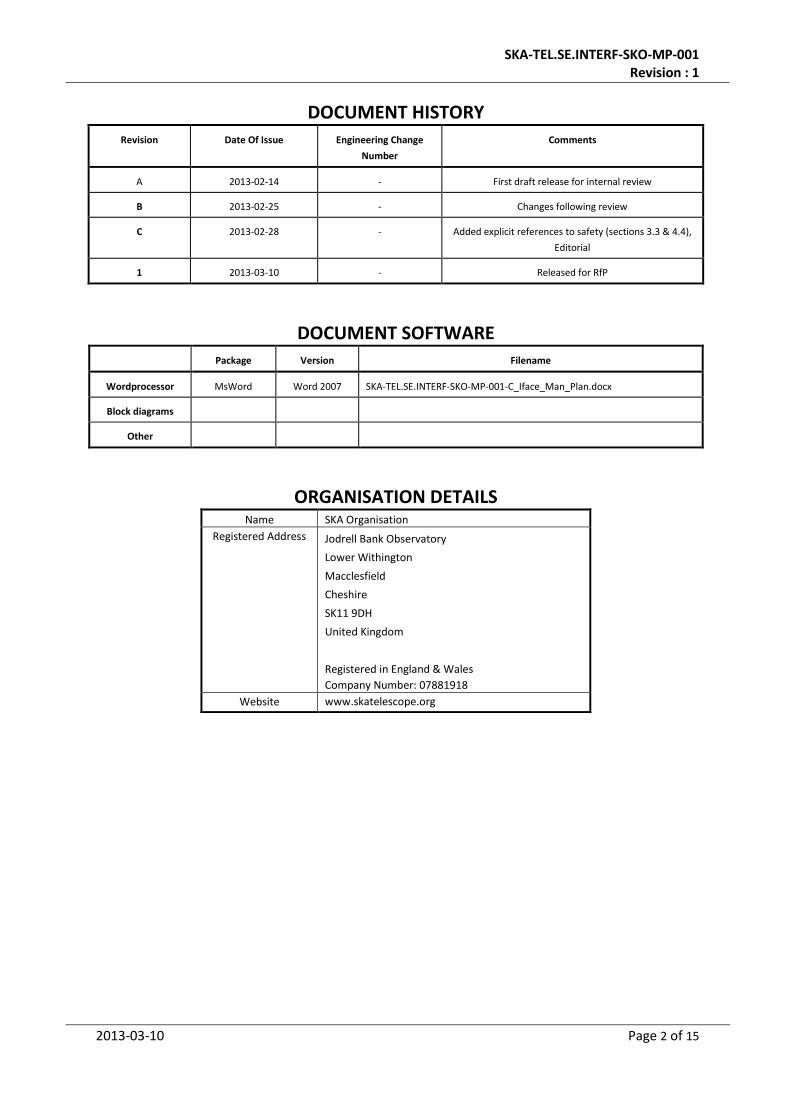
DOCUMENT HISTORY Revision Date Of Issue Engineering Change
Number
Comments
A 2013-02-14 - First draft release for internal review
B 2013-02-25 - Changes following review
C 2013-02-28 - Added explicit references to safety (sections 3.3 & 4.4),
Editorial
1 2013-03-10 - Released for RfP
DOCUMENT SOFTWARE Package Version Filename
Wordprocessor MsWord Word 2007 SKA-TEL.SE.INTERF-SKO-MP-001-C_Iface_Man_Plan.docx
Block diagrams
Other
ORGANISATION DETAILS Name SKA Organisation
Registered Address Jodrell Bank Observatory
Lower Withington
Macclesfield
Cheshire
SK11 9DH
United Kingdom
Registered in England & Wales
Company Number: 07881918
Website www.skatelescope.org
SKA-TEL.SE.INTERF-SKO-MP-001 Revision : 1
2013-03-10 Page 3 of 15
TABLE OF CONTENTS
1 INTRODUCTION ............................................................................................. 6
1.1 Purpose of the document ....................................................................................................... 6 1.2 Scope of the document ........................................................................................................... 6
2 REFERENCES ................................................................................................ 7
2.1 Applicable documents............................................................................................................. 7 2.2 Reference documents ............................................................................................................. 7
3 INTRODUCTION ............................................................................................. 8
3.1 Roles and responsibilities........................................................................................................ 8 3.2 Interface identification and allocation .................................................................................... 9
3.2.1 Identification ................................................................................................................... 9 3.2.2 Allocation Principles ........................................................................................................ 9 3.2.3 Element Party Allocation................................................................................................. 9
3.3 Interface Description ............................................................................................................ 10
4 THE INTERFACE CONTROL DOCUMENT .............................................................. 10
4.1 Introductory sections ............................................................................................................ 11 4.2 Specification class list and applicable standards .................................................................. 11 4.3 Test, diagnostic or maintenance features ............................................................................ 11 4.4 Safety aspects ....................................................................................................................... 11 4.5 Interface specifications by class ............................................................................................ 11
4.5.1 Mechanical .................................................................................................................... 12 4.5.2 Fluidic ............................................................................................................................ 12 4.5.3 Thermal ......................................................................................................................... 12 4.5.4 Electromagnetic ............................................................................................................ 12 4.5.5 Optical ........................................................................................................................... 12 4.5.6 Electrical ........................................................................................................................ 12 4.5.7 Electronic ...................................................................................................................... 12 4.5.8 Electro-optical ............................................................................................................... 12 4.5.9 Data exchange specifications ........................................................................................ 13 4.5.10 Human-Machine Interfaces .......................................................................................... 13
4.6 Interface Verification ............................................................................................................ 13
5 PROCESS FOR THE DEFINITION OF ELEMENT INTERFACES ........................................ 13
5.1 Element Interface Development Teams ............................................................................... 13 5.2 Interface Advisory Board ...................................................................................................... 13
6 APPENDIX – DATA TRANSMISSION ICD SCHEME EXAMPLE ..................................... 15
SKA-TEL.SE.INTERF-SKO-MP-001 Revision : 1
2013-03-10 Page 4 of 15
LIST OF FIGURES Figure 1: An example of controls for inter-Element interfaces illustrated using the OSI model.......... 15
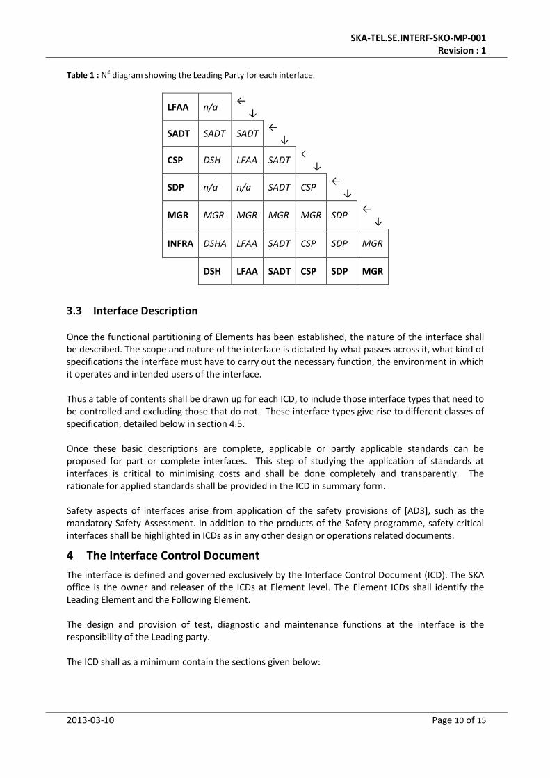
LIST OF TABLES Table 1 : N2 diagram showing the Leading Party for each interface. .................................................... 10
SKA-TEL.SE.INTERF-SKO-MP-001 Revision : 1
2013-03-10 Page 5 of 15
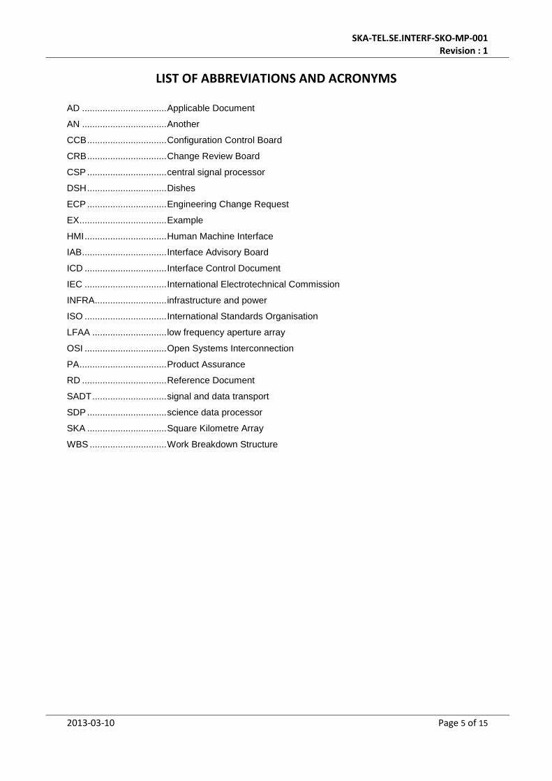
LIST OF ABBREVIATIONS AND ACRONYMS
AD ................................. Applicable Document
AN ................................. Another
CCB ............................... Configuration Control Board
CRB ............................... Change Review Board
CSP ............................... central signal processor
DSH ............................... Dishes
ECP ............................... Engineering Change Request
EX .................................. Example
HMI ................................ Human Machine Interface
IAB ................................. Interface Advisory Board
ICD ................................ Interface Control Document
IEC ................................ International Electrotechnical Commission
INFRA ............................ infrastructure and power
ISO ................................ International Standards Organisation
LFAA ............................. low frequency aperture array
OSI ................................ Open Systems Interconnection
PA .................................. Product Assurance
RD ................................. Reference Document
SADT ............................. signal and data transport
SDP ............................... science data processor
SKA ............................... Square Kilometre Array
WBS .............................. Work Breakdown Structure

SKA-TEL.SE.INTERF-SKO-MP-001 Revision : 1
2013-03-10 Page 6 of 15
1 Introduction
1.1 Purpose of the document
This document outlines the preparation of Interface Control Documents and describes how they are to be used and managed.
1.2 Scope of the document
This document describes the management of engineering interfaces within the SKA project. The document forms part of the system engineering management for the SKA project. Whilst dealing explicitly with Element interfaces, this document may also be made applicable to Element internal interfaces at the option of Consortia. Engineering dependencies (such as requirements and resource allocations which must be traded across multiple Elements) are not the subject of this Management Plan. The Interface Management Plan will ultimately address the following issues:
Identification of the interfaces between Elements
Assignment of responsibility and authority for interface management
Identification of the aspects of the interfaces to be documented in Interface Control Documents including precise technical definitions of interface data flows and protocols where applicable
The technical strategy for developing, testing and deploying the interface including specification of the requirements, design and testing documentation required
Specification of the management and technical skills required for the associated development work, at each phase of the project life cycle
Configuration Management and Quality Management procedures relevant to interface development including identification of major reviews
Interface development risks and risk management strategies
SKA-TEL.SE.INTERF-SKO-MP-001 Revision : 1
2013-03-10 Page 7 of 15
2 References
2.1 Applicable documents
The following documents are applicable to the extent stated herein. In the event of conflict between the contents of the applicable documents and this document, the applicable documents shall take precedence.
[AD1] Document Requirements Descriptions SKA-TEL.SE.M&T-SKO-DRD-001 Rev A [AD2] SKA Change Management Procedure SKA-TEL.SE.CDM-SKO-PR-001 Rev B [AD3] PA & S Plan
2.2 Reference documents
The following documents are referenced in this document. In the event of conflict between the contents of the referenced documents and this document, this document shall take precedence.
[RD1] SKA WBS [RD2] SKA Baseline Design [RD3] International ISO/IEC Standard 7498-1. Second edition 1994-11-15. Corrected and
reprinted 1996-06-15, Information technology — Open Systems Interconnection — Basic Reference Model: The Basic Model

SKA-TEL.SE.INTERF-SKO-MP-001 Revision : 1
2013-03-10 Page 8 of 15
3 Introduction
The SKA telescope systems are comprised of Elements which together form the topmost architecture of each of the two systems. They are described in the work breakdown structure document [RD1]. Interface definition and management will be one of the key aspects underpinning the project. During the initial phases of the project, interfaces will be identified and high level requirements will be captured in the requirements specifications. This will be followed by the development of separate documents to control the interfaces (see below) and as the design of each particular piece of equipment progresses, the interfaces will be refined. These documents will exist on all levels of the project with varying degrees of detail and will include mechanical, functional, data and electrical aspects. A high level interface register will be compiled and maintained at System level by the SKA Office. Within this register the owners, the parties involved, the type of interface, and the status of interface agreements will be identified. Whilst it is not the intention that this register includes all the interface control documents for the project, a database will be deployed at Element and Sub-Element level (at least) which will. The ‘owner’ of an interface will be the party that oversees the development and eventual agreement of the Interface Control Document (ICD). The owner will also ensure that rigorous configuration control be exercised on the document once signed [AD2]. At no stage can one party (including the owner) change/modify an interface without the approval of all parties affected by the change including the relevant systems engineer or SKA Office Element System Engineer. ICDs must be clear and unambiguous and thorough review and discussion of each document will be essential.
3.1 Roles and responsibilities
The Office of the SKA Organisation is the owner of all interfaces between Elements, between SKA sites and centres, and between SKA and the outside world. All agreements and control documents governing these interfaces are under SKA Office control. The SKA Office is responsible for the initial identification and description of each interface and the nomination of Leading and Following Elements in each case (see below). Element Work Package Consortia are responsible for the implementation of interfaces. For each bilateral interface, a Leading Element and a Following Element are nominated, and the Leading Element proposes the nature of the implementation. Element Work Package Consortia are also responsible (as owners) for the establishment, control and management of interfaces internal to the Elements. Ownership of interfaces is a critical aspect of the interface management in SKA and should be differentiated from the process of engineering the telescope system at Element level and below. The work of developing interfaces will be the responsibility of interface development teams – see section 5.1. The control of Element level interfaces will be the role of an Interface Advisory Board as a special case of the Change Review Board in the SKA Change Management process [AD2] – see section 5.2. Interface verification responsibilities are detailed in section 4.6 below.
SKA-TEL.SE.INTERF-SKO-MP-001 Revision : 1
2013-03-10 Page 9 of 15
3.2 Interface identification and allocation
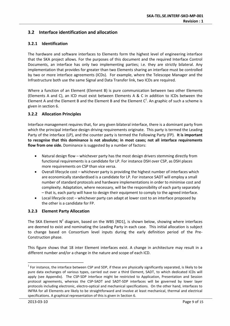
3.2.1 Identification
The hardware and software interfaces to Elements form the highest level of engineering interface that the SKA project allows. For the purposes of this document and the required Interface Control Documents, an interface has only two implementing parties; i.e. they are strictly bilateral. Any implementation that provides for greater than two Elements sharing an interface must be controlled by two or more interface agreements (ICDs). For example, where the Telescope Manager and the Infrastructure both use the same Signal and Data Transfer link, two ICDs are required. Where a function of an Element (Element B) is pure communication between two other Elements (Elements A and C), an ICD must exist between Elements A & C in addition to ICDs between the Element A and the Element B and the Element B and the Element C1. An graphic of such a scheme is given in section 6.
3.2.2 Allocation Principles
Interface management requires that, for any given bilateral interface, there is a dominant party from which the principal interface design driving requirements originate. This party is termed the Leading Party of the interface (LP), and the counter party is termed the Following Party (FP). It is important to recognise that this dominance is not absolute; in most cases; not all interface requirements flow from one side. Dominance is suggested by a number of factors:
Natural design flow – whichever party has the most design drivers stemming directly from functional requirements is a candidate for LP. For instance DSH over CSP, as DSH places more requirements on CSP than vice versa.
Overall lifecycle cost – whichever party is providing the highest number of interfaces which are economically standardised is a candidate for LP. For instance SADT will employ a small number of standard protocols and hardware implementations in order to minimise cost and complexity. Adaptation, where necessary, will be the responsibility of each party separately – that is, each party will have to design their equipment to comply to the agreed interface.
Local lifecycle cost – whichever party can adapt at lower cost to an interface proposed by the other is a candidate for FP.
3.2.3 Element Party Allocation
The SKA Element N2 diagram, based on the WBS [RD1], is shown below, showing where interfaces are deemed to exist and nominating the Leading Party in each case. This initial allocation is subject to change based on Consortium level inputs during the early definition period of the Pre-Construction phase. This figure shows that 18 inter Element interfaces exist. A change in architecture may result in a different number and/or a change in the nature and scope of each ICD.
1 For instance, the interface between CSP and SDP, if these are physically significantly separated, is likely to be
pure data exchanges of various types, carried out over a third Element, SADT, to which dedicated ICDs will apply (see Appendix). The CSP-SDP interface might be restricted to Application, Presentation and Session protocol agreements, whereas the CSP-SADT and SADT-SDP interfaces will be governed by lower layer protocols including electronic, electro-optical and mechanical specifications. On the other hand, interfaces to INFRA for all Elements are likely to be straightforward and involve at least mechanical, thermal and electrical specifications. A graphical representation of this is given in Section 6.
SKA-TEL.SE.INTERF-SKO-MP-001 Revision : 1
2013-03-10 Page 10 of 15
Table 1 : N2 diagram showing the Leading Party for each interface.
LFAA n/a ← ↓
SADT SADT SADT ← ↓
CSP DSH LFAA SADT ← ↓
SDP n/a n/a SADT CSP ← ↓
MGR MGR MGR MGR MGR SDP ← ↓
INFRA DSHA LFAA SADT CSP SDP MGR
DSH LFAA SADT CSP SDP MGR
3.3 Interface Description
Once the functional partitioning of Elements has been established, the nature of the interface shall be described. The scope and nature of the interface is dictated by what passes across it, what kind of specifications the interface must have to carry out the necessary function, the environment in which it operates and intended users of the interface. Thus a table of contents shall be drawn up for each ICD, to include those interface types that need to be controlled and excluding those that do not. These interface types give rise to different classes of specification, detailed below in section 4.5. Once these basic descriptions are complete, applicable or partly applicable standards can be proposed for part or complete interfaces. This step of studying the application of standards at interfaces is critical to minimising costs and shall be done completely and transparently. The rationale for applied standards shall be provided in the ICD in summary form. Safety aspects of interfaces arise from application of the safety provisions of [AD3], such as the mandatory Safety Assessment. In addition to the products of the Safety programme, safety critical interfaces shall be highlighted in ICDs as in any other design or operations related documents.
4 The Interface Control Document
The interface is defined and governed exclusively by the Interface Control Document (ICD). The SKA office is the owner and releaser of the ICDs at Element level. The Element ICDs shall identify the Leading Element and the Following Element. The design and provision of test, diagnostic and maintenance functions at the interface is the responsibility of the Leading party. The ICD shall as a minimum contain the sections given below:
SKA-TEL.SE.INTERF-SKO-MP-001 Revision : 1
2013-03-10 Page 11 of 15
4.1 Introductory sections
Scope and purpose
Applicable and Reference documents, including applicable standards
Roles and responsibilities, nominating Owner, leading party and following party with points of contact for each
Interface scope, listing classes of interface specification included
Interface topology – describe whether the interface uses another Element transparently, and reference to the associated ICDs
Summary of Standards rationales
4.2 Specification class list and applicable standards
These will be one or more of:
Mechanical (structural, loading, tooling, etc)
Fluid (pneumatic, cooling, heating, condensate, fuels, lubricants, waste, exhaust, feedstocks etc)
Thermal (cooling, heating, heatsinking, etc )
Electromagnetic (DC field, RF, etc)
Optical (numerical aperture, focal position, etc)
Electrical (i.e. conducted power)
Electronic (i.e. conducted signals or data)
Electro-optical (generally signals or data)
Data exchange specifications (protocol stack)
Human-Machine Interface (special combination of some of the above)
Applicable standards shall be given under each class.
4.3 Test, diagnostic or maintenance features
Any design features provided at the interface exclusively for testing, diagnosis or maintenance procedures, for the interface itself, shall be documented in this section. The presentation of these features shall follow the same logic as that for the main interface.
4.4 Safety aspects
See Section 3.3 above.
4.5 Interface specifications by class
In the absence of applicable standards, interfaces must be explicitly described using conventional representations such as engineering drawings, pinouts, logic and circuit diagrams, etc. Any given interface control document will, in general, contain several classes of specification as given below. All classes or aspects of the interface which have an influence over the expected performance must be documented in the ICD. Classes of specification necessarily overlap. Classification shall be as convenient, whilst using the class list as a checklist for completeness.
SKA-TEL.SE.INTERF-SKO-MP-001 Revision : 1
2013-03-10 Page 12 of 15
4.5.1 Mechanical
Not only shall the mechanical connection of an interface be given, but also access (and where relevant dynamic) volumes shall be shown. Any mounting/demounting tooling and support equipment and their volumetric requirements shall be given. The required fasteners and the responsibility for supply shall be described. Where relevant, the loading (including dynamic) environment at the interface shall be given. Aspects of the interface environment (such as loading) may require substantial iteration due to sensitivity to design beyond the interface. The status of the affected specification shall be given (‘preliminary’, ‘final’) in this section.
4.5.2 Fluidic
The nature and specification of the fluid shall be given. The pressure and flow regime shall be given, along with a broad temperature specification if uncontrolled. The interface fittings, including materials and responsibility for supply shall be specified. Access, tooling etc shall be given if not already specified in the Mechanical section.
4.5.3 Thermal
Where the function of an interface is primarily thermal; i.e. it provides heating, cooling or temperature stability, all specifications, such as fastener torques, flatness, etc may be grouped in this section. Of particular importance are the design temperatures, thermal power handling capacity, etc, and these shall be the minimum provided here.
4.5.4 Electromagnetic
All specifications that minimise loss and interference shall be given explicitly here. Quasi-optical RF interfaces should not be documented here but in the following section.
4.5.5 Optical
Where the transfer of information is implemented optically or quasi-optically (i.e. through reflection or refraction but excluding electro-optical signal or data transfer), the optical characteristics of the interface shall be described in this section.
4.5.6 Electrical
This class is intended to capture the specification of electrical power interfaces. Load values, power factor, in-rush characteristics, short and long term voltage/frequency fluctuations, spikes, surges, etc., shall be documented in this section, in addition to the basic parameters such as voltage and frequency. The corresponding connectors and the responsibility for supply shall be described.
4.5.7 Electronic
This class is intended to document the specification of conducted signal interfaces. In addition to the basic signal characteristics, the nominal calibration of signals shall be given here where relevant. The corresponding connectors and the responsibility for supply shall be described.
4.5.8 Electro-optical
This form of analogue or digital signal transmission, where not fully conforming to recognised standards, shall be documented regarding all significant design parameters such as wavelength, coupling, fibre type where applicable, etc. The corresponding connectors and the responsibility for supply shall be described.
SKA-TEL.SE.INTERF-SKO-MP-001 Revision : 1
2013-03-10 Page 13 of 15
4.5.9 Data exchange specifications
Using a model of process interactions such as the Open Systems Interconnection standard [RD3], the data exchange between interfacing entities shall be fully described in this section.
4.5.10 Human-Machine Interfaces
Whilst not applicable for inter-Element interfaces, HMIs that exist elsewhere shall be documented according to a TBD standard.
4.6 Interface Verification
Interface verification occurs at many stages in the integration of the Elements. It is carried out to demonstrate that the design and implementation conform to the ICD, and it will be described in formal procedures. A key distinction is made between verification tests that require the interfacing Element and those that do not (using a simulator or standard test equipment). The ICD shall contain a section on the verification methods to be used to:
1 Verify the design and implementation of interfacing hardware and software without the interface being made
2 Verify the interface for integration and acceptance purposes (involving the interface being made)
It is required that the Leading interfacing party is responsible for specifying verification methods and procedures, and for executing them in the second case above. The execution of the first case is the responsibility of the respective interfacing parties.
5 Process for the definition of Element interfaces
The first definition of the interfaces shall rest with the SKA project office. These shall be provided to suppliers (consortia) in draft form. The interfaces are foreseen to evolve during the design phase. The process for interface evolution shall be clear (see below) and involve all three parties to the interface, the SKA office as the owner and the two Elements involved.
5.1 Element Interface Development Teams
Under the leadership of the SKA system engineering team, interface development teams shall be assembled from the consortia undertaking the supply work for the SKA project. These teams are constituted and managed as part of the Integrated Task Team (ITT) activity at System level, but with a dedicated remit to concern themselves with specific Element to Element interfaces. These interface ITTs shall be established at the earliest possible moment and will be required to deliver agreed and documented interfaces at the latest at the end of the stage 1.
5.2 Interface Advisory Board
While Minor change requests may be accepted without formal analysis by the Configuration Control Board [AD2], all changes on the inter-Element interfaces are deemed to be Major and therefore require a Change Review Board (CRB). In this context the CRB for interfaces is established herein as the Interface Advisory Board. The Interface Advisory Board (IAB) is convened at any time an Engineering Change Request (ECR) is issued on an ICD. The IAB advises the SKA CCB and provides a recommendation to the chair of the CCB.

SKA-TEL.SE.INTERF-SKO-MP-001 Revision : 1
2013-03-10 Page 14 of 15
Ex-officio members of the IAB are the SKA Project Manager, the SKA Chief System Engineer, the Element System Engineers and the system engineers of the Element engineering teams. Additional engineering or other persons may be asked to participate at the discretion of the SKA project manager.
SKA-TEL.SE.INTERF-SKO-MP-001 Revision : 1
2013-03-10 Page 15 of 15
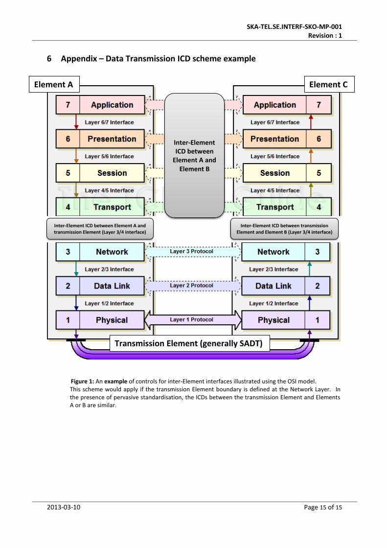
6 Appendix – Data Transmission ICD scheme example
Figure 1: An example of controls for inter-Element interfaces illustrated using the OSI model. This scheme would apply if the transmission Element boundary is defined at the Network Layer. In the presence of pervasive standardisation, the ICDs between the transmission Element and Elements A or B are similar.
Inter-Element ICD between Element A and transmission Element (Layer 3/4 interface)
Inter-Element ICD between
Element A and Element B
Inter-Element ICD between transmission Element and Element B (Layer 3/4 interface)
Element A Element C
Transmission Element (generally SADT)