Embed Size (px)
Citation preview

SK-1131-SPQAccess Control Keypad
with Proximity Card ReaderManual
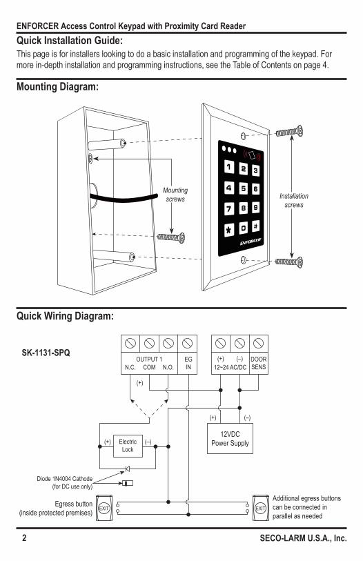
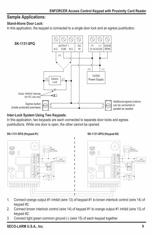
Egress button (inside protected premises)
Additional egress buttons can be connected in parallel as needed
12VDC Power Supply
(+)
(+)
(+)
(–)
(–)ElectricLock
12~24 AC/DC(+) (–) DOOR
SENSOUTPUT 1 EG
INN.C. COM N.O.
Diode 1N4004 Cathode(for DC use only)
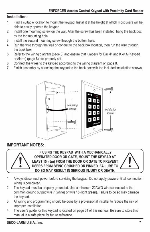
Mounting screws Installation
screws
2
ENFORCER Access Control Keypad with Proximity Card Reader
SECO-LARM U.S.A., Inc.
Quick Installation Guide:
Mounting Diagram:
Quick Wiring Diagram:
This page is for installers looking to do a basic installation and programming of the keypad. For more in-depth installation and programming instructions, see the Table of Contents on page 4.
SK-1131-SPQ
3
ENFORCER Access Control Keypad with Proximity Card Reader
SECO-LARM U.S.A., Inc.
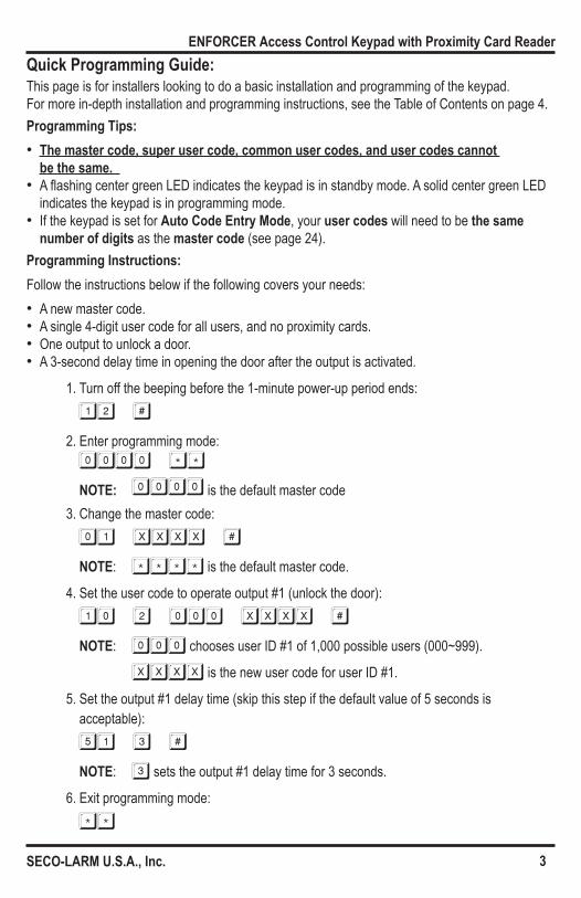
Quick Programming Guide:This page is for installers looking to do a basic installation and programming of the keypad. For more in-depth installation and programming instructions, see the Table of Contents on page 4.Programming Tips: • The master code, super user code, common user codes, and user codes cannot
be the same. • A flashing center green LED indicates the keypad is in standby mode. A solid center green LED
indicates the keypad is in programming mode. • If the keypad is set for Auto Code Entry Mode, your user codes will need to be the same
number of digits as the master code (see page 24).Programming Instructions:Follow the instructions below if the following covers your needs: • A new master code. • A single 4-digit user code for all users, and no proximity cards. • One output to unlock a door. • A 3-second delay time in opening the door after the output is activated.
1. Turn off the beeping before the 1-minute power-up period ends:
12 #2. Enter programming mode:
0000 **NOTE: 0000 is the default master code
3. Change the master code:
01 xxxx #NOTE: **** is the default master code.
4. Set the user code to operate output #1 (unlock the door):
10 2 000 xxxx #NOTE: 000 chooses user ID #1 of 1,000 possible users (000~999).
XXXX is the new user code for user ID #1.
5. Set the output #1 delay time (skip this step if the default value of 5 seconds is acceptable):
51 3 #NOTE: 3 sets the output #1 delay time for 3 seconds.
6. Exit programming mode:
**
4
ENFORCER Access Control Keypad with Proximity Card Reader
SECO-LARM U.S.A., Inc.
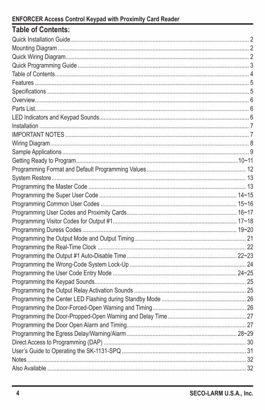
Table of Contents:Quick Installation Guide ..................................................................................................................... 2Mounting Diagram ............................................................................................................................. 2Quick Wiring Diagram ........................................................................................................................ 2Quick Programming Guide ................................................................................................................ 3Table of Contents ............................................................................................................................... 4Features ............................................................................................................................................ 5Specifications .................................................................................................................................... 5Overview ............................................................................................................................................ 6Parts List ............................................................................................................................................ 6LED Indicators and Keypad Sounds .................................................................................................. 6Installation ......................................................................................................................................... 7IMPORTANT NOTES ........................................................................................................................ 7Wiring Diagram .................................................................................................................................. 8Sample Applications .......................................................................................................................... 9Getting Ready to Program ..........................................................................................................10~11Programming Format and Default Programming Values ................................................................. 12System Restore ............................................................................................................................... 13Programming the Master Code ....................................................................................................... 13Programming the Super User Code .......................................................................................... 14~15Programming Common User Codes ......................................................................................... 15~16Programming User Codes and Proximity Cards ........................................................................ 16~17Programming Visitor Codes for Output #1 ................................................................................. 17~18Programming Duress Codes ..................................................................................................... 19~20Programming the Output Mode and Output Timing ......................................................................... 21Programming the Real-Time Clock ................................................................................................. 22Programming the Output #1 Auto-Disable Time ........................................................................ 22~23Programming the Wrong-Code System Lock-Up ............................................................................ 24Programming the User Code Entry Mode ................................................................................. 24~25Programming the Keypad Sounds ................................................................................................... 25Programming the Output Relay Activation Sounds ......................................................................... 25Programming the Center LED Flashing during Standby Mode ....................................................... 26Programming the Door-Forced-Open Warning and Timing ............................................................. 26Programming the Door-Propped-Open Warning and Delay Time ................................................... 27Programming the Door Open Alarm and Timing.............................................................................. 27Programming the Egress Delay/Warning/Alarm ........................................................................ 28~29Direct Access to Programming (DAP) ............................................................................................. 30User’s Guide to Operating the SK-1131-SPQ ................................................................................. 31Notes ............................................................................................................................................... 32Also Available .................................................................................................................................. 32

5
ENFORCER Access Control Keypad with Proximity Card Reader
SECO-LARM U.S.A., Inc.
Features:
Specifications:Operating voltage 12~24 VDC/VAC
Current draw (at 12VDC)
Standby 66mAKeypress 93mAOutput 1 active 99mAOutput 1 & 2 active 126mAOutput 1, 2, & 3 active 127mATotal max current draw 160mA
Outputs
#1 – Form C 1A@30VDC#2 – Form C 1A@30VDC#3 – Transistor ground 100mA@24VDCK or A 100mA@24VDCDuress 100mA@24VDCInterlock 100mA@24VDCTamper 50mA@24VDC
InputsEgress N.O. GroundDoor sensor N.C. GroundDoor inhibit N.O. Ground
Proximity reader frequency 125kHz (EM125)Proximity reader sensing distance 11/2” (38mm)Operating temperature -4°~158° F (-20°~70° C)Operating humidity 5~95% Non-condensingDimensions (including back box) 45/8”x27/8”x11/2” (117x73x38 mm)Weight 6-oz (170g)
• Built-in proximity card reader • 12~24 VDC/VAC Auto-adjusting operation • Up to 1,000 possible user codes (000~999)
and/or proximity cards programmable for output #1, 100 (001~100) for output #2, 100 (001~100) for output #3
• Up to 50 (01~50) possible temporary visitor codes, which can be programmed for one-time or limited-time use (1~99 hours)
• Output #1: Form C relay, 1A@30VDC max. • Output #2: Form C relay, 1A@30VDC max. • Output #3: Transistor ground, 100mA@24VDC • Outputs #1, #2, and #3 can be programmed to
activate for up to 99,999 seconds (nearly 28 hours) • Tamper output: N.C. Dry contact, 50mA@24VDC
max. • Keypad illuminates when a button is pressed;
backlight can be programmed for FULL or AUTO in standby mode
• Mounts to a standard single-gang back box (surface-mount back box included)
• All features are programmed directly from the keypad: No need for an external programmer
• EEPROM Memory protects programmed information in case of power loss
• Up to 50 (01~50) duress codes for output #1, 10 (01~09) for output #2, 10 (01~09) for output #3
• Duress code signals a silent alarm if an authorized user is forced to open the door under duress
• Egress input lets users exit the premises without keying in the code
• Door sensor input for anti-tailgating operation • Interlocking input for connecting to a second
keypad • Keypad active or alarm output selectable via
jumper
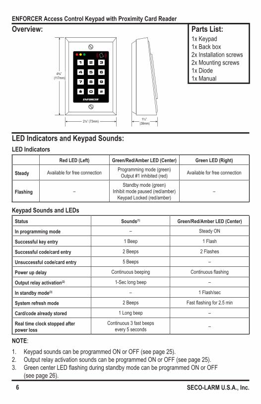
27⁄8” (73mm) 1½” (38mm)
45⁄8” (117mm)
6
ENFORCER Access Control Keypad with Proximity Card Reader
SECO-LARM U.S.A., Inc.
Overview:
LED Indicators and Keypad Sounds:
Parts List:1x Keypad 1x Back box 2x Installation screws 2x Mounting screws 1x Diode 1x Manual
Keypad Sounds and LEDsStatus Sounds(1) Green/Red/Amber LED (Center)
In programming mode – Steady ON
Successful key entry 1 Beep 1 Flash
Successful code/card entry 2 Beeps 2 Flashes
Unsuccessful code/card entry 5 Beeps –
Power up delay Continuous beeping Continuous flashing
Output relay activation(2) 1-Sec long beep –
In standby mode(3) – 1 Flash/sec
System refresh mode 2 Beeps Fast flashing for 2.5 min
Card/code already stored 1 Long beep –
Real time clock stopped after power loss
Continuous 3 fast beeps every 5 seconds –
NOTE:1. Keypad sounds can be programmed ON or OFF (see page 25).2. Output relay activation sounds can be programmed ON or OFF (see page 25).3. Green center LED flashing during standby mode can be programmed ON or OFF
(see page 26).
LED IndicatorsRed LED (Left) Green/Red/Amber LED (Center) Green LED (Right)
Steady Available for free connection Programming mode (green)Output #1 inhibited (red) Available for free connection
Flashing –Standby mode (green)
Inhibit mode paused (red/amber)Keypad Locked (red/amber)
–
Mounting screws Installation
screws
7
ENFORCER Access Control Keypad with Proximity Card Reader
SECO-LARM U.S.A., Inc.
Installation:
IMPORTANT NOTES:
1. Find a suitable location to mount the keypad. Install it at the height at which most users will be able to easily operate the keypad.
2. Install one mounting screw on the wall. After the screw has been installed, hang the back box by the top mounting hole.
3. Install the second mounting screw through the bottom hole.4. Run the wire through the wall or conduit to the back box location, then run the wire through
the back box.5. Refer to the wiring diagram (page 8) and ensure that jumpers for Backlit and K or A (Keypad
or Alarm) (page 8) are properly set.6. Connect the wires to the keypad according to the wiring diagram on page 8.7. Finish assembly by attaching the keypad to the back box with the included installation screws.
1. Always disconnect power before servicing the keypad. Do not apply power until all connection wiring is completed.
2. The keypad must be properly grounded. Use a minimum 22AWG wire connected to the common ground output wire 7 (white) or wire 15 (light green). Failure to do so may damage the keypad.
3. All wiring and programming should be done by a professional installer to reduce the risk of improper installation.
4. The user’s guide for this keypad is located on page 31 of this manual. Be sure to store this manual in a safe place for future reference.
IF USING THE KEYPAD WITH A MECHANICALLY OPERATED DOOR OR GATE, MOUNT THE KEYPAD AT
LEAST 15’ (5m) FROM THE DOOR OR GATE TO PREVENT USERS FROM BEING CRUSHED OR PINNED. FAILURE TO
DO SO MAY RESULT IN SERIOUS INJURY OR DEATH.
DOOR
SENS
(+)
(
-)12
~24 V
AC/V
DCEG IN
OUTP
UT 1
N.C.
C
OM
N.O
.
1 2 3 4 5 6 7 8 9 10 11 12 13 14 15 16
FULL AUTO
BACKLIT
KEY ALARM
K or A
Backlit jumperK or A jumper
Conn
ectio
n te
rmina
ls
Connection wires
8
ENFORCER Access Control Keypad with Proximity Card Reader
SECO-LARM U.S.A., Inc.
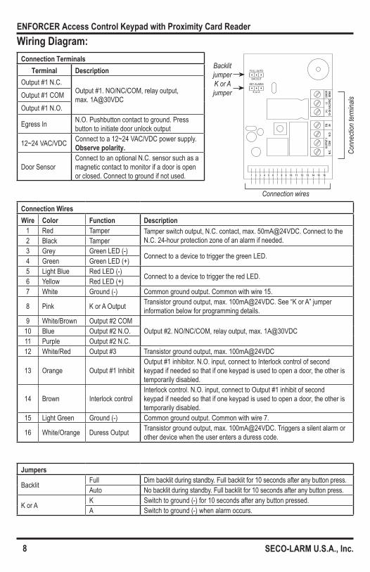
Connection WiresWire Color Function Description
1 Red Tamper Tamper switch output, N.C. contact, max. 50mA@24VDC. Connect to the N.C. 24-hour protection zone of an alarm if needed.2 Black Tamper
3 Grey Green LED (-) Connect to a device to trigger the green LED.4 Green Green LED (+)5 Light Blue Red LED (-) Connect to a device to trigger the red LED.6 Yellow Red LED (+)7 White Ground (-) Common ground output. Common with wire 15.
8 Pink K or A Output Transistor ground output, max. 100mA@24VDC. See “K or A” jumper information below for programming details.
9 White/Brown Output #2 COMOutput #2. NO/NC/COM, relay output, max. 1A@30VDC10 Blue Output #2 N.O.
11 Purple Output #2 N.C.12 White/Red Output #3 Transistor ground output, max. 100mA@24VDC
13 Orange Output #1 InhibitOutput #1 inhibitor. N.O. input, connect to Interlock control of second keypad if needed so that if one keypad is used to open a door, the other is temporarily disabled.
14 Brown Interlock controlInterlock control. N.O. input, connect to Output #1 inhibit of second keypad if needed so that if one keypad is used to open a door, the other is temporarily disabled.
15 Light Green Ground (-) Common ground output. Common with wire 7.
16 White/Orange Duress Output Transistor ground output, max. 100mA@24VDC. Triggers a silent alarm or other device when the user enters a duress code.
Connection TerminalsTerminal Description
Output #1 N.C.Output #1. NO/NC/COM, relay output, max. 1A@30VDCOutput #1 COM
Output #1 N.O.
Egress In N.O. Pushbutton contact to ground. Press button to initiate door unlock output
12~24 VAC/VDC Connect to a 12~24 VAC/VDC power supply. Observe polarity.
Door SensorConnect to an optional N.C. sensor such as a magnetic contact to monitor if a door is open or closed. Connect to ground if not used.
Wiring Diagram:
Jumpers
Backlit Full Dim backlit during standby. Full backlit for 10 seconds after any button press.Auto No backlit during standby. Full backlit for 10 seconds after any button press.
K or A K Switch to ground (-) for 10 seconds after any button pressed.A Switch to ground (-) when alarm occurs.
Egress button (inside protected premises)
Additional egress buttons can be connected in parallel as needed
12VDC Power Supply
(+)
(+)
(+)
(–)
(–)ElectricLock
12~24 AC/DC(+) (–) DOOR
SENSOUTPUT 1 EG
INN.C. COM N.O.
Diode 1N4004 Cathode(for DC use only)
DOOR
SENS
(+)
(
-)12
~24 V
AC/V
DCEG IN
OUTP
UT 1
N.C.
C
OM
N.O
.
1 2 3 4 5 6 7 8 9 10 11 12 13 14 15 16
FULL AUTO
BACKLIT
KEY ALARM
K or A
DOOR
SENS
(+)
(
-)12
~24 V
AC/V
DCEG IN
OUTP
UT 1
N.C.
C
OM
N.O
.
1 2 3 4 5 6 7 8 9 10 11 12 13 14 15 16
FULL AUTO
BACKLIT
KEY ALARM
K or A
ElectricLock
N.C.MagneticDoor Contact
(–)
(+)
(+)
(–)
(+)
(–)12VDC
Power Supply
ElectricLock
N.C.MagneticDoor Contact
(–)(+)
12VDC Power Supply
SK-1131-SPQ
SK-1131-SPQ (Keypad #1) SK-1131-SPQ (Keypad #2)
9
ENFORCER Access Control Keypad with Proximity Card Reader
SECO-LARM U.S.A., Inc.
Sample Applications:Stand-Alone Door Lock: In this application, the keypad is connected to a single door lock and an egress pushbutton.
Inter-Lock System Using Two Keypads: In this application, two keypads are each connected to separate door locks and egress pushbuttons. While one door is open, the other cannot be opened.
1. Connect orange output #1 inhibit (wire 13) of keypad #1 to brown interlock control (wire 14) of keypad #2.
2. Connect brown interlock control (wire 14) of keypad #1 to orange output #1 inhibit (wire 13) of keypad #2.
3. Connect light green common ground (-) (wire 15) of each keypad together.
10
ENFORCER Access Control Keypad with Proximity Card Reader
SECO-LARM U.S.A., Inc.
Getting Ready to Program:Codes and/or Cards:The SK-1131-SPQ can be set to be activated by users in one of three ways:1. Keypad code only – There are five types of keypad codes:
• Master code – Used only for entering programming mode; there can be only one master code per keypad.
• Super user code – Can be used to activate outputs #1, #2, and #3, or to disable (inhibit) or enable the operation of the outputs.
• User codes – Unique codes for each user to activate outputs #1, #2, or #3. • Visitor codes – Temporary user codes that can be assigned to visitors or temporary
workers to activate output #1; the visitor codes can be programmed for one-time use or to expire after a set number of hours has passed.
• Duress codes – Assigned to specific users as a way to send a silent alert if forced to use the keypad under duress.
2. Proximity card only – Standard 125kHz (EM125) proximity cards can be used to activate output #1, output #2, or output #3.
3. Card/fob + code – For enhanced security, the user can be required to also enter a code after tapping a proximity card/fob. The code may be unique to each card or to a group of users, or a common code can be used with all cards.
Security Levels:There are four possible security levels for the SK-1131-SPQ:1. Card only – The most basic, convenient level of security. Hold a previously-programmed
proximity card over the keypad to activate outputs #1, #2, or #3 (see “Programming User Codes and Proximity Cards” on pages 16~17).
2. User code only – Type in a 4- to 8-digit user code to activate outputs #1, #2, or #3 (see pages 16~17).
3. Card + Common user code – All valid proximity cards can be programmed with a single common user code so that outputs #1, #2, or #3 can only be activated if one of the cards and the common user code are used together. The common user code is automatically assigned when each proximity card is programmed into the keypad (see “Programming Common User Codes” on pages 15~16).
4. Card + Unique user code – The most secure level. Each proximity card can be programmed with its own unique user code so that outputs #1, #2, or #3 can only be activated if the card and the unique code are used together (see pages 16~17).

11
ENFORCER Access Control Keypad with Proximity Card Reader
SECO-LARM U.S.A., Inc.
Getting Ready to Program (cont.):Power Up the Keypad:When the keypad is first powered up, it will beep continuously for about 1 minute. During this power-up time, if needed, use Direct Access to Programming (DAP) to reset the master code (see “Direct Access to Programming (DAP)” on page 30).1. Turn off the beeping before the 1-minute power-up period ends:
12 #This will immediately stop the beeping.When the beeping has ended, the keypad is ready for normal operation or for programming.
Enter and Exit Programming Mode:All programming of the keypad is done in programming mode.1. Enter programming mode:
xxxx **
NOTE: XXXX is the master code. 0000 is the default master code (see “Programming the Master Code” on page 13 to program a new master code). The center green LED will turn to a steady ON to indicate that the keypad is in programming mode.
2. Exit programming mode:
**
The ** entry can be used to exit programming mode at any time while programming. The center green LED will return to flashing, indicating standby mode, upon exiting programming mode.NOTE: DO NOT DISCONNECT THE KEYPAD FROM POWER WHILE IN
PROGRAMMING MODE. Disconnecting the keypad while in programming mode could cause a keypad memory error.
12
ENFORCER Access Control Keypad with Proximity Card Reader
SECO-LARM U.S.A., Inc.
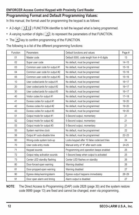
Programming Format and Default Programming Values:In this manual, the format used for programming the keypad is as follows:
• A 2-digit ( XX ) FUNCTION identifier to tell the keypad what is being programmed. • A varying number of digits ( X ) to represent the parameters of that FUNCTION. • The # key to confirm programming of the FUNCTION.
The following is a list of the different programming functions:
Function Parameters Default functions and values Page #01 Master code Default 0000, code length from 4~8 digits 1302 Super user code No default, must be programmed 14~1503 Common user code for output #1 No default, must be programmed 15~1604 Common user code for output #2 No default, must be programmed 15~1605 Common user code for output #3 No default, must be programmed 15~1610 User codes/cards for output #1 No default, must be programmed 16~1720 User codes/cards for output #2 No default, must be programmed 16~1730 User codes/cards for output #3 No default, must be programmed 16~1740 Visitor codes for output #1 No default, must be programmed 17~1841 Duress codes for output #1 No default, must be programmed 19~2042 Duress codes for output #2 No default, must be programmed 19~2043 Duress codes for output #3 No default, must be programmed 19~2051 Output mode for output #1 5-Second output, momentary 2152 Output mode for output #2 5-Second output, momentary 2153 Output mode for output #3 5-Second output, momentary 2155 System real-time clock No default, must be programmed 2256 Output #1 auto-disable time No default, must be programmed 22~2360 Wrong-code system lock-up Locks keypad after 10 false code/card tries 2470 User code entry mode Manual entry of “#” after each code 24-2571 Keypad sounds Programming and operation beeps enabled 2572 Output relay activation sounds 1-Second beep when output is activated 2573 Center LED standby flashing Center LED flashes on standby 2680 Door-forced-open warning Warning disabled 2681 Door-propped-open warning Warning disabled 2790 Egress delay/warning/alarm Egress output happens immediately 28~2991 Door open alarm and timing Alarm output is disabled 27
NOTE: The Direct Access to Programming (DAP) code 2828 (page 30) and the system restore code 9999 (page 13) are fixed and cannot be changed, even via programming.
13
ENFORCER Access Control Keypad with Proximity Card Reader
SECO-LARM U.S.A., Inc.
System Restore:
Programming the Master Code:
System restore will reset all programming values except the master code back to the default values shown on page 12.1. Make sure the keypad is in programming mode (see “Enter and Exit Programming Mode” on
page 11).2. Initiate system restore:
9999 #NOTE: • System restore will reset ALL programming except the master code back to default values. Be
careful to use system restore only when absolutely necessary. • System restore may take several minutes. The center green LED will flash rapidly during this
time. • Once system restore has been completed, the keypad will beep twice to show that all
programming values have been reset to their default values and are ready to be re-programmed.
• At this point, the keypad is still in programming mode.
The master code is used to enter programming mode. The master code does not serve as a user code for activating outputs #1, #2, or #3.1. Make sure the keypad is in programming mode (see “Enter and Exit Programming Mode” on
page 11).2. Enter new master code:
01 xxxx #NOTE:
• XXXX represents the new master code, which can be 4 to 8 digits long. • There can be only one master code for the keypad. • Programming a new master code will overwrite the previous master code. • If the master code is forgotten, use Direct Access to Programming (DAP) to reset the master
code (see page 30). • The master code, super user code, common user codes, and user codes cannot
be the same. • If the keypad is set for Auto Code Entry Mode, user codes will need to be the same number
of digits as the master code (see “Programming the User Code Entry Mode” on pages 24~25).
14
ENFORCER Access Control Keypad with Proximity Card Reader
SECO-LARM U.S.A., Inc.
Programming the Super User Code:The super user code has two functions: • Unlike user codes, the super user code can activate or deactivate output #1, output #2, and
output #3 at any time. • The super user code can also enable or disable output #1. An administrator may want to disable
output #1 in the evening or on the weekend to prevent other users from entering a protected premises.
• The super user code is exempt from any system inhibition or lockup functions. It is valid at any time.
Programming the Super User Code:1. Make sure the keypad is in programming mode (see “Enter and Exit Programming Mode” on
page 11).2. Enter the new super user code:
02 xxxx #NOTE:
• XXXX represents the new super user code, which can be 4 to 8 digits long. • There can be only one super user code for the keypad. • Programming a new super user code will overwrite the previous super user code. • The master code, super user code, common user codes, and user codes cannot
be the same. Deleting the Super User Code:This function is useful for protecting the premises in case the super user code is forgotten.To delete a super user code:1. Make sure the keypad is in programming mode (see page 11).2. Enter:
02 #Using the Super User Code:
In these examples, assume the super user code is 2580.1. Activate or deactivate output #1 (timed or toggle, depending on programming):
2580 # 12. Activate or deactivate output #2 (timed or toggle, depending on programming):
2580 # 23. Activate or deactivate output #3 (timed or toggle, depending on programming):
2580 # 3

15
ENFORCER Access Control Keypad with Proximity Card Reader
SECO-LARM U.S.A., Inc.
Programming the Super User Code (cont.):
Programming Common User Codes:
4. To toggle operation of output #1 ON or OFF:
2580 # 7NOTE: • This function is used to leave output #1 active for extended periods of time. • Do not forget to deactivate this function after its use is no longer required. • It is recommended to only use this function with fail-safe locks.
5. To temporarily pause or restart the timed output #1 disable period:
2580 # 8NOTE: • This function is used to enable the operation of output #1 if it was disabled using the output
#1 auto-disable function (see pages 22~23). • When the output #1 auto-disable function is inactive, the red LED will flash steadily. This
indicates that output #1 may now be used. 6. Disable or enable output #1 (toggle, regardless of programming):
2580 # 9NOTE: • For more information on programming timed or toggle mode, see “Programming the Output
Mode and Output Timing” on page 21. • The center LED will flash red and amber while output #1 is disabled. • For safety reasons, the egress button works regardless of whether output #1 is enabled or
disabled via the super user code. • The super user code continues to operate output #1 even while that output is disabled.
This function allows a common user code to be automatically added to each proximity card as it is programmed. Every proximity card user also uses the same common user code to operate outputs #1, #2, or #3. This provides greater security than programming the keypad to operate with the card alone. It is also more convenient than assigning each user a unique user code, although unique user codes offer an even greater degree of security.1. To program a common user code for output #1:
03 xxxx #2. To program a common user code for output #2:
04 xxxx #3. To program a common user code for output #3:
05 xxxx #
16
ENFORCER Access Control Keypad with Proximity Card Reader
SECO-LARM U.S.A., Inc.
Programming User Codes and Proximity Cards:When programming user codes and/or proximity cards, use this general formula:
AA B CCC DDDD #A – Output
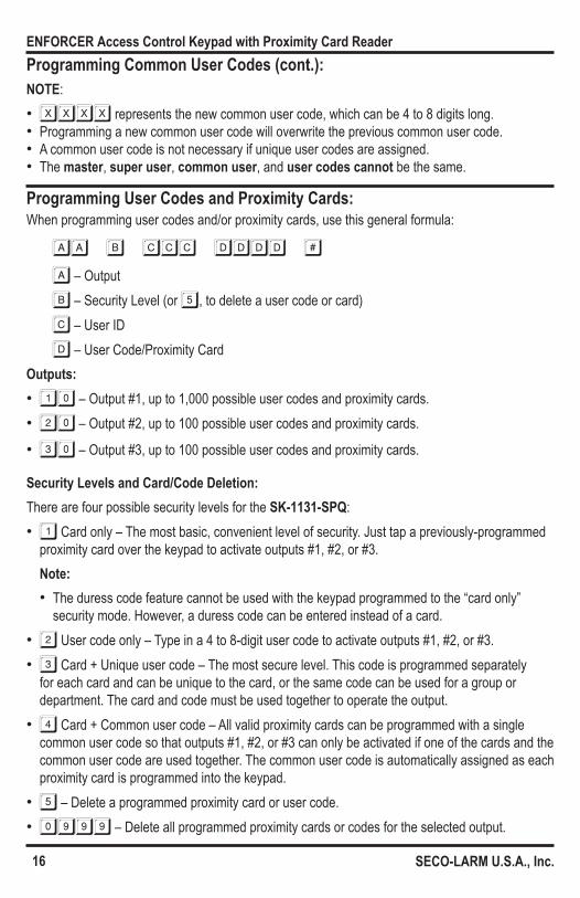
B – Security Level (or 5, to delete a user code or card)
C – User ID
D – User Code/Proximity CardOutputs: • 10 – Output #1, up to 1,000 possible user codes and proximity cards. • 20 – Output #2, up to 100 possible user codes and proximity cards.
• 30 – Output #3, up to 100 possible user codes and proximity cards.
Security Levels and Card/Code Deletion:There are four possible security levels for the SK-1131-SPQ: • 1 Card only – The most basic, convenient level of security. Just tap a previously-programmed
proximity card over the keypad to activate outputs #1, #2, or #3. Note: • The duress code feature cannot be used with the keypad programmed to the “card only”
security mode. However, a duress code can be entered instead of a card. • 2 User code only – Type in a 4 to 8-digit user code to activate outputs #1, #2, or #3. • 3 Card + Unique user code – The most secure level. This code is programmed separately
for each card and can be unique to the card, or the same code can be used for a group or department. The card and code must be used together to operate the output.
• 4 Card + Common user code – All valid proximity cards can be programmed with a single common user code so that outputs #1, #2, or #3 can only be activated if one of the cards and the common user code are used together. The common user code is automatically assigned as each proximity card is programmed into the keypad.
• 5 – Delete a programmed proximity card or user code. • 0999 – Delete all programmed proximity cards or codes for the selected output.
Programming Common User Codes (cont.):NOTE: • XXXX represents the new common user code, which can be 4 to 8 digits long. • Programming a new common user code will overwrite the previous common user code. • A common user code is not necessary if unique user codes are assigned. • The master, super user, common user, and user codes cannot be the same.

17
ENFORCER Access Control Keypad with Proximity Card Reader
SECO-LARM U.S.A., Inc.
Programming User Codes and Proximity Cards (cont.):
Programming Visitor Codes for Output #1:
User IDs: • 000 to 999 – 1,000 unique user IDs for user codes and prox cards for output #1. • 001 to 100 – 100 unique user IDs for user codes and/or prox cards for output #2 or
output #3.User Codes: • A user code can be 4 to 8 digits long, and must have the same length as the master code if the
keypad is used in auto code entry mode (see pages 24~25). • The master, super user, common user, and user codes cannot be the same.
Examples:1. Program only a proximity card for user ID #017 for output #1:
10 1 017 READ CARD #2. Program a user code for user ID #010 for output #1:
10 2 010 2275 #3. Delete a proximity card for output #1:
10 5 READ CARD #4. Delete code or proximity card stored in position #002 for output #1:
10 5 002 #5. Delete all users for output #1:
10 09996. Program a proximity card for user ID #001 for output #1 for use with a common user code.
10 4 001 READ CARD #7. Program a proximity card for user ID #023 for output #2 for use with a unique user code.
20 3 023 READ CARD 2468 #
Visitor codes are temporary codes that expire after use or after a specified amount of time has elapsed. While active, they operate output #1 as normal user codes.NOTE: • If a visitor code is programmed using a number previously programmed as a user code, the
visitor code will be kept and the user code will be replaced. • Visitor codes cannot be used to deactivate the duress output (see “Operating Duress Codes” on
page 20).If the keypad is powered down, any programmed visitor codes will be deleted.

18
ENFORCER Access Control Keypad with Proximity Card Reader
SECO-LARM U.S.A., Inc.
Programming Visitor Codes for Output #1 (cont.):When programming visitor codes, use this general formula:
40 aa bb cccc #
40 – Program Visitor Codes
a – Visitor ID
b – Valid Duration (hours)
c – Visitor Code
Visitor IDs:
• 01 to 50 – 50 unique visitor IDs for visitor codes for output #1.
• 0999 – Delete all currently programmed visitor codes.Valid Duration:
• 00 – Set a one-time code. This code can only be used once by a visitor, after which it is automatically deleted.
• 01 to 99 – Set the duration the visitor code will be valid, from 1 to 99 hours. Visitor Codes: • A visitor code can be 4 to 8 digits long, and must have the same length as the master code if
the keypad is used in auto code entry mode (see “Programming the User Code Entry Mode” on pages 24~25).
• All visitor codes are deleted if power is lost.Examples:1. Set the visitor ID #1 code to 1268, and make it a one-time code:
40 01 00 1268 #2. Set the visitor ID #2 code to 1378, and make it valid for three hours:
40 02 03 1378 #3. Delete the visitor ID #2 code from memory:
40 02 #4. Delete all currently programmed visitor codes:
40 0999 #
19
ENFORCER Access Control Keypad with Proximity Card Reader
SECO-LARM U.S.A., Inc.
Programming Duress Codes:Duress codes allow users to trigger a silent alarm or alert if they are forced to allow access to a protected area. If a user uses a duress code instead of his or her normal user code, outputs #1, #2, or #3 will activate as normal, but the duress output will simultaneously activate to trigger a silent alarm or alert.NOTE: • Duress codes are always valid and are not inhibited by any other operation of the keypad. • Duress codes can not be the same as any other user codes. • Duress codes can be used either as stand-alone codes or in conjunction with a user card,
depending on how the user codes are programmed (see “Programming User Codes and Proximity Cards” on page 16).
• The duress code should be easy to remember. For instance, it can be the same as a user’s normal user code, but with a single digit changed, as by subtracting or adding 1 to the first or last digit of the code. For example, if the user code is 1369, a good duress code might be 2369.
When programming duress codes, use this general formula:
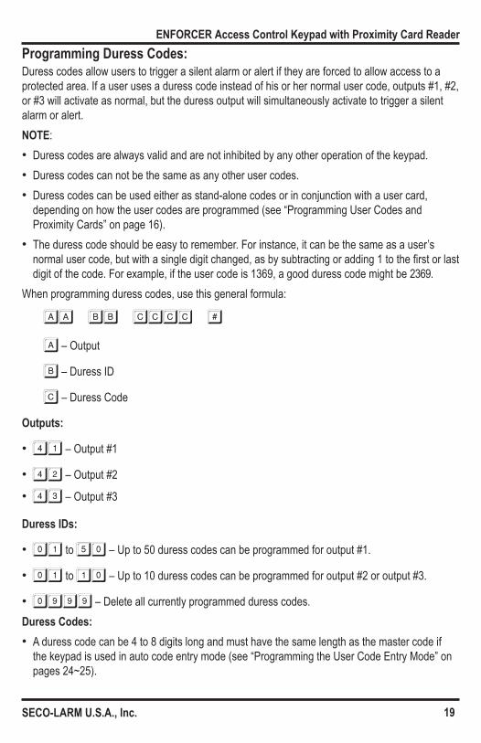
AA BB CCCC #
a – Output
b – Duress ID
c – Duress Code
Outputs:
• 41 – Output #1
• 42 – Output #2
• 43 – Output #3
Duress IDs:
• 01 to 50 – Up to 50 duress codes can be programmed for output #1.
• 01 to 10 – Up to 10 duress codes can be programmed for output #2 or output #3.
• 0999 – Delete all currently programmed duress codes.Duress Codes: • A duress code can be 4 to 8 digits long and must have the same length as the master code if
the keypad is used in auto code entry mode (see “Programming the User Code Entry Mode” on pages 24~25).
20
ENFORCER Access Control Keypad with Proximity Card Reader
SECO-LARM U.S.A., Inc.
Programming Duress Codes (cont.):Examples:1. Set the duress ID #1 code for output #1 to 1360:
41 01 1360 #2. Set the duress ID #1 code for output #2 to 23980:
42 01 23980 #3. Delete the duress ID #1 code for output #1 from memory:
41 01 #4. Delete all duress codes for output #1 from memory:
41 0999 #Operating Duress Codes:If a duress code is used in place of a normal user code, both the appropriate outputs #1, #2, or #3 and the duress output will be activated. However, a duress code cannot deactivate the duress output. Only a normal user code/card, super user code, or a master code can deactivate the duress output. NOTE: A duress code can also be used in conjunction with a user card to activate the duress
output. However, a user card alone cannot activate the duress output.Examples:
In these examples, assume that 1360 is an output #1 duress code and that 1369 is a user code.1. Activate the duress output and output #1 using the duress code:
1360 #NOTE: Subsequently entering the duress code will activate output #1 again, but will not
deactivate the duress output.
2. Deactivate the duress output using the user code:
1369 #3. Activate the duress output and activate output #1 using the duress code and a user card:
READ CARD 1360 #

21
ENFORCER Access Control Keypad with Proximity Card Reader
SECO-LARM U.S.A., Inc.
Programming the Output Mode and Output Timing:The relays for outputs #1, #2, and #3 can be programmed to trigger ON and OFF with a user code or user card (toggle mode), or to trigger for a programmed length of time of up to nearly 28 hours before automatically turning OFF. The toggle or timed outputs can be used for locking or unlocking a door or for a variety of functions that can be controlled with the keypad.When programming the output mode and time, use this general formula:
aa bbbbb #
A – Output
B – Output Mode and Time
Outputs:
• 51 – Output #1 • 52 – Output #2 • 53 – Output #3
Output Mode and Time:
• 0 – Start/stop (toggle) mode. In this case, the output starts when a user code and/or user card is entered, and stops when a user code and/or card is entered.
• 1 to 99999 – The output triggered by a user code and/or user card lasts 1 to 99,999 seconds (nearly 28 hours) before automatically turning off (default 5 seconds).
NOTE: While the keypad is in momentary timed output mode, the output can be reset any time by entering the super user code.
Examples:
In these examples, assume that the super user code is 2580.1. In programming mode, set output #1 to toggle:
51 0 #2. In programming mode, set output #2 to 60 seconds:
52 60 #3. Reset output #1 timer:
2580 # 14. Reset output #2 timer:
2580 # 2

22
ENFORCER Access Control Keypad with Proximity Card Reader
SECO-LARM U.S.A., Inc.
Programming the Real-Time Clock:A 24-hour real-time clock provides the baseline time needed to start and stop the output #1 auto-disable time (see “Programming the Output #1 Auto-Disable Time” below). If the output #1 Auto-Disable Time is not programmed, it is not necessary to set the real-time clock.To set the clock, use this general formula:
55 HHMM #
55 – Program Real-Time Clock
HH – Hours
MM – Minutes
Setting Hours and Minutes:
• HH represents hours and MM represents minutes in the military (24-hour) time format, from 00:00 to 23:59.
Examples: • Set the real-time clock to 11:30 AM:
55 1130 # • Set the real-time clock to 7:15 PM:
55 1915 #NOTE: • If the output #1 auto-disable time is programmed, losing power will cause the keypad to beep
3 times every 5 seconds. To deactivate this alert, either reset the real-time clock or clear the output #1 auto-disable time.
• If the output #1 auto-disable time is not programmed, losing power will not cause the keypad to beep.
The keypad can be programmed so that output #1 is disabled for a certain period of time every day. Output #1 will be disabled at the start time, and will be re-enabled at the end time. This ensures that users are not allowed into the protected premises, such as during lunch hour or at night.NOTE: • The real-time clock must be operating in order to set the output #1 auto-disable time (see
“Programming the Real-Time Clock” above). • For safety purposes, the egress button still works while output #1 is auto-disabled. • The time is set using the military (24-hour) time format (00:00 to 23:59).
Programming the Output #1 Auto-Disable Time:
23
ENFORCER Access Control Keypad with Proximity Card Reader
SECO-LARM U.S.A., Inc.
• If the programmed start time is before the end time, output #1 is auto-disabled within a single day. If the programmed start time is after the end time, the end time will be on the following day.
• The start time and end time cannot be the same. • The auto-disable time can be temporarily paused and restarted using the super user code (see
“Programming the Super User Code” on pages 14~15). • During the output #1 auto-disable time, the super user code can be used to operate output #1 • The keypad’s center LED will flash red and amber during the output #1 auto-disable time.
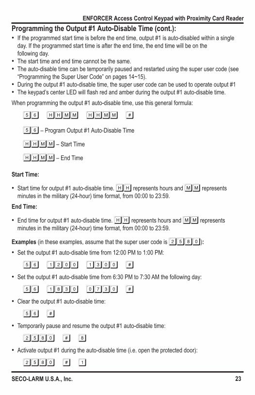
When programming the output #1 auto-disable time, use this general formula:
56 HHMM HHMM #
56 – Program Output #1 Auto-Disable Time
HHMM – Start Time
HHMM – End Time
Start Time:
• Start time for output #1 auto-disable time. HH represents hours and MM represents minutes in the military (24-hour) time format, from 00:00 to 23:59.
End Time:
• End time for output #1 auto-disable time. HH represents hours and MM represents minutes in the military (24-hour) time format, from 00:00 to 23:59.
Examples (in these examples, assume that the super user code is 2580): • Set the output #1 auto-disable time from 12:00 PM to 1:00 PM:
56 1200 1300 # • Set the output #1 auto-disable time from 6:30 PM to 7:30 AM the following day:
56 1830 0730 # • Clear the output #1 auto-disable time:
56 # • Temporarily pause and resume the output #1 auto-disable time:
2580 # 8 • Activate output #1 during the auto-disable time (i.e. open the protected door):
2580 # 1
Programming the Output #1 Auto-Disable Time (cont.):
24
ENFORCER Access Control Keypad with Proximity Card Reader
SECO-LARM U.S.A., Inc.
Programming the Wrong-Code System Lock-Up:The keypad can be programmed to lock up in order to secure the premises against unauthorized entry if multiple wrong codes are entered or multiple wrong user cards are tapped.When programming the wrong-code system lock-up, use this general formula:
60 aa #
60 – Program Wrong-Code System Lock-Up
AA – Lock Options
Lock Options:Choose from several different options for the wrong-code system lock-up security level: • 1 – After 10 successive false attempts using incorrect user codes or user cards, the keypad
will lock for 60 seconds (default).
• 2 – After 10 successive false attempts using incorrect user codes or user cards, the duress output will activate. The duress output can be deactivated using any user code or user card, or via the super user code.
• 5 to 10 – After 5 to 10 successive false attempts using incorrect user codes or user cards, the keypad will lock for 15 minutes or until the super user code is used as follows:
SUPER USER CODE # 9 • 00 – No system lock-up will happen.
NOTE: The keypad’s center LED will flash red and amber to show that the keypad is locked. The duress code will still function in this mode.
Programming the User Code Entry Mode:The keypad can be programmed for auto or manual user code entry modes: • Auto entry mode – Pressing the # key is not required after typing in a user code. In auto entry
mode, all user codes must have the same number of digits as the master code. • Manual entry mode – The # key must be pressed after the user code to indicate the code has
been entered completely. In this case, the user codes can have a different number of digits, from 4 to 8 digits.
To Program: • For auto entry mode:
70 1 # • For manual entry mode (default):
70 2 #

25
ENFORCER Access Control Keypad with Proximity Card Reader
SECO-LARM U.S.A., Inc.
Programming the User Code Entry Mode (cont.):NOTE: If the keypad was previously programmed for manual code entry mode and then is
reprogrammed for auto entry mode, any codes whose length exceeds the number of digits of the master code will no longer operate the keypad. However, if the keypad is reprogrammed for manual entry mode, the longer codes will again operate the keypad.
Programming the Keypad Sounds:Some of the keypad sounds can be programmed off: • Keypad audible mode – All the keypad’s status beeps are enabled. • Keypad silent mode – The successful key entry beep (1 beep) and the unsuccessful user code
or card entry beeps (5 beeps) are disabled. However, the warning and power-up delay beeps remain active. This provides for a quieter work environment.
To Program: • To enable keypad audible mode (default):
71 1 # • To enable keypad silent mode:
71 0 #NOTE: This programming function only impacts the keypad sounds. It does not impact the output
relay activation sounds (see “Programming the Output Relay Activation Sounds” below).
Programming the Output Relay Activation Sounds:The keypad output sounds can be programmed for one of three modes:1. No beeps – The keypad will not beep when an output is activated.
72 0 #2. 1-second beep (default) – The keypad will beep for 1 second when an output is activated.
72 1 #3. 2 short beeps – The keypad will beep twice when an output is activated:
72 2 #NOTE: This programming function only impacts the output relay activation sounds. It does not
impact the keypad sounds (see “Programming the Keypad Sounds” above).
26
ENFORCER Access Control Keypad with Proximity Card Reader
SECO-LARM U.S.A., Inc.
Programming the Center LED Flashing during Standby Mode:The keypad’s center green LED typically flashes while the keypad is in standby mode, but can be programmed off if needed.1. Enable center green LED flashing during standby mode (default):
73 1 #2. Disable center green LED flashing during standby mode:
73 0 #
Programming the Door-Forced-Open Warning and Timing:If the keypad is connected to an optional magnetic contact or other door protection switch or device, the keypad can be programmed to beep when a door has been forced open. The keypad beep can be set to activate for 1 to 999 seconds.1. Door-forced-open warning OFF (default):
80 0 #2. Door-forced-open warning ON:
80 ttt #NOTE:
• TTT represents the beep and alarm output active time, which can be set from 1 to 999 seconds.
• If programmed for door-forced-open warning, the keypad will beep if the door is forced open without using a user code and/or card or the egress button. The keypad will not beep if the door is opened with a user code and/or card or the egress button.
• The door-forced-open warning and the door open alarm should not both be enabled, as the overlap in timing could result in incorrect alarm outputs (see “Programming the Door Open Alarm and Timing” on page 27).

27
ENFORCER Access Control Keypad with Proximity Card Reader
SECO-LARM U.S.A., Inc.
Programming the Door-Propped-Open Warning and Delay Time:If the keypad is connected to an optional magnetic contact or other door protection switch or device, the keypad can be programmed to beep when a door has been propped open. This prompts authorized users to close a door that was not closed properly or to investigate a door that may have been deliberately propped open.1. Door-propped-open warning OFF (default):
81 0 #2. Door-propped-open warning ON:
81 ttt #NOTE:
• TTT represents the delay time, which can be set from 1 to 999 seconds. • The delay time provides time for a door to close normally before triggering the
door-propped-open warning. • The door-propped-open beeping will stop when the open door is closed.
Programming the Door Open Alarm and Timing:When the keypad is connected to a magnetic contact or other door monitoring device, it can be programmed to trigger the alarm output for 1 to 999 seconds if the door is opened. In this case, if the alarm output is triggered, the output either automatically ends at the end of the programmed time or when a user code or super user code is input for output #1. NOTE: • If programmed for door open alarm, the alarm will sound if the door is forced open without using
a user code and/or card. No alarm will sound if the door is opened with a user code and/or card. • The door open alarm and door-forced-open warning should not both be enabled, as the overlap
in timing could result in incorrect alarm output (see “Programming the Door-Forced-Open Warning and Timing on page 26).
To Program:1. Door open alarm OFF (default):
91 0 #2. Door open alarm ON:
91 TTT #
NOTE: TTT represents the alarm output time, which can be set from 1 to 999 seconds.
28
ENFORCER Access Control Keypad with Proximity Card Reader
SECO-LARM U.S.A., Inc.
Programming the Egress Delay/Warning/Alarm:With most keypads, the egress button provides a simple way for someone inside a protected premises to exit through a locked door by pressing a button instead of using a keypad. However, in some situations, delaying the egress operation and/or providing some warning or alarm when the egress button is used is desirable.For example, in hospitals or schools, it may be desirable to delay the egress operation and provide a warning to prevent patients or young children from easily leaving the protected area.For simple egress with no delay, warning, or alarm, do not change this setting. It is disabled by default.When programming the egress delay/warning/alarm, use this general formula:
90 a bb #
90 – Program Egress Delay/Warning/Alarm
A – Egress Mode
BB – Delay TimeEgress Modes:There are six possible egress operation configurations for the SK-1131-SPQ:
• 1 Momentary contact with no warning or alarm (default) – Press the egress button momentarily for silent egress operation.
• 2 Momentary contact with warning beep – Press the egress button momentarily. The keypad will beep for the programmed delay time before letting the door open, to warn that someone is preparing to exit the protected area.
• 3 Momentary contact with warning beep and alarm – Press the egress button momentarily. The keypad will beep for the programmed delay time and activate the alarm output before letting the door open, to warn that someone is preparing to exit the protected area.
• 4 Hold contact with no warning or alarm – Press and hold the egress button for the programmed delay time until the door is open. This prevents accidental opening of the door.
• 5 Hold contact with warning beep – Press and hold the egress button for the programmed delay time until the door is open. The keypad will beep during the delay time before letting the door open, to warn that someone is preparing to exit the protected area.
• 6 Hold contact with warning beep and alarm output – Press and hold the egress button for the programmed delay time until the door is open. The keypad will beep during the delay time and activate the alarm output before letting the door open, to warn that someone is preparing to exit the protected area.

29
ENFORCER Access Control Keypad with Proximity Card Reader
SECO-LARM U.S.A., Inc.
Programming the Egress Delay/Warning/Alarm (cont.):NOTE: When the egress button is programmed to hold for a delay time before the door is
released, it is important to put a sign near the egress button to notify users of the delay time.
Delay Time: • 0 – No delay time (default): Output #1 operates immediately when the egress button is pressed. • 1 to 99 – Egress button delay time: The delay time can be set from 1 to 99 seconds. This tells
the keypad how long to wait after the egress button is pressed before activating output #1.Examples:1. Momentary mode – Press the egress button, and the keypad will beep for 5 seconds before
output #1 activates:
90 2 5 #2. Hold button to activate – Press and hold the egress button for 10 seconds, and the keypad will
beep for those 10 seconds before output #1 activates:
90 5 10 #3. Return to default setting – Press the egress button to activate output #1 with no beeping or
delay:
90 1 0 #NOTE: For safety and to avoid confusion, when a delay or a press-and-hold delay is programmed, please post a notice near the egress button, such as: “Press and hold the button for 5 seconds or until the door is unlocked.”
30
ENFORCER Access Control Keypad with Proximity Card Reader
SECO-LARM U.S.A., Inc.
Direct Access to Programming (DAP):Direct Access to Programming (DAP) is used to reset the master code if it is forgotten. DAP will not change the programming of the SK-1131-SPQ in any other way.
To Use DAP:1. Disconnect the keypad’s power.2. Wait one minute to ensure that the keypad’s power is fully discharged.3. Reconnect the power. The keypad will beep repeatedly for one minute.4. While the keypad is beeping, press the egress button once to stop the beeping.5. Enter the DAP code:
2828 **6. The center green LED will now turn ON, indicating that the keypad is ready for a new master
code to be programmed.NOTE: • See “Programming the Master Code” on page 13 for how to program a new master code. • Direct Access to Programming (DAP) will not reset the keypad’s programming. It will only enter
programming mode in order to program a new master code.

31
ENFORCER Access Control Keypad with Proximity Card Reader
SECO-LARM U.S.A., Inc.
User’s Guide to Operating the SK-1131-SPQ:See “Programming the Master Code” and “Programming the Super User Code” on pages 13~15 for functions specific to those authorized to use those codes.Opening the Door:In these examples, assume that the user code is 2275, the common user code is
3526, and a unique user code is 2468. • Security Level 1 – Card only
READ CARD1 Long beep indicates that the door can be opened.
• Security Level 2 – Code only
2275 #*
1 Long beep indicates that the door can be opened. • Security Level 3 – Card + Common user code
READ CARD2 Short beeps and a rapidly flashing center green LED indicates the card is accepted and the keypad is waiting for the Common user code.
3526 #*
1 Long beep indicates that the door can be opened. • Security Level 4 – Card + Unique user code
READ CARD2 Short beeps and a rapidly flashing center green LED indicates the card is accepted and the keypad is waiting for the Unique user code.
2468 #*
1 Long beep indicates that the door can be opened.NOTE: For more information on security levels, please see “Getting Ready to Program” on page 10.
Operating the Egress Button:Press the egress button from inside the protected premises to unlock the door and exit without using the keypad.NOTE: For more information on programming the Egress button, please see “Programming the Egress Delay/Warning/Alarm” on pages 28~29.
* The # key is not needed if the keypad is programmed for auto entry mode. See pages 24~25.
32
ENFORCER Access Control Keypad with Proximity Card Reader
SECO-LARM U.S.A., Inc.
FCC COMPLIANCE STATEMENT FCC ID: K4E1131SPQTHIS DEVICE COMPLIES WITH PART 15 OF THE FCC RULES. OPERATION IS SUBJECT TO THE FOLLOWING TWO CONDITIONS: (1) THIS DEVICE MAY NOT CAUSE HARMFUL INTERFERENCE AND (2) THIS DEVICE MUST ACCEPT ANY INTERFERENCE RECEIVED, INCLUDING INTERFERENCE THAT MAY CAUSE UNDESIRED OPERATIONNotice: The changes or modifications not expressly approved by the party responsible for compliance could void the user’s authority to operate the equipment.IMPORTANT NOTE: To comply with the FCC RF exposure compliance requirements no change to the antenna or the device is permitted. Any change to the antenna or the device could result in the device exceeding the RF exposure requirements and voice user’s authority.
LIMITED LIFETIME WARRANTY: This SECO-LARM product is warranted against defects in material and work-manship while used in normal service for the lifetime of the product. SECO-LARM’s obligation is limited to the repair or replacement of any defective part if the unit is returned, transportation prepaid, to SECO-LARM. This Warranty is void if damage is caused by or attributed to acts of God, physical or electrical misuse or abuse, neglect, repair or alteration, improp-er or abnormal usage, or faulty installation, or if for any other reason SECO-LARM determines that such equipment is not operating properly as a result of causes other than defects in material and workmanship. The sole obligation of SECO-LARM and the purchaser’s exclusive remedy, shall be limited to the replacement or repair only, at SECO-LARM’s option. In no event shall SECO-LARM be liable for any special, collateral, incidental, or consequential personal or property damage of any kind to the purchaser or anyone else. This limited lifetime warranty is for products sold and installed in the United States and Canada. For all other countries the warranty is 1 (one) year.
NOTICE: The information and specifications printed in this manual are current at the time of publication. However, the SECO-LARM policy is one of continual development and improvement. For this reason, SECO-LARM reserves the right to change specifications without notice. SECO-LARM is also not responsible for misprints or typographical errors.Copyright © 2015 SECO-LARM U.S.A., Inc. All rights reserved. This material may not be reproduced or copied, in whole or in part, without the written permission of SECO-LARM.
SECO-LARM® U.S.A., Inc.16842 Millikan Avenue, Irvine, CA 92606 Website: www.seco-larm.com PIHAK1
Phone: (949) 261-2999 | (800) 662-0800 Email: [email protected] MiSK-1131-SPQ_150708.indd
Notes:
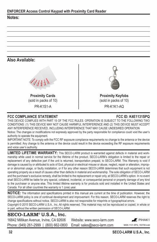
Also Available:
Proximity Cards (sold in packs of 10)
Proximity Keyfobs(sold in packs of 10)
PR-K1S1-A PR-K1K1-AQ