Embed Size (px)
Citation preview

http://www.prewell.com 1
Drive Amplifier
SJM PREWELL
PNH15
Version 10
Description
The PNH15 is a high performance InGaP HBT MMIC Amplifier and
high linearity driver amplifier in high quality surface-mounted plastic
SOT-89 package. The PNH15 features excellent input/output return
loss and high linear performance. The device can be easily
matched to obtain optimum power and linearity. The product is
targeted for using as driver and power amplifier for wireless
infrastructure applications. The PNH15 operates from a single
voltage and has an internal active bias. All devices are 100% RF and
DC tested.
Specifications
1) Test Conditions : T=25°C, Supply Voltage=5V, 50ohm System
2) OIP3 measured with two tones at an output power of 9dBm/tone separated by 1MHz.
Absolute Maximum Ratings
Parameter Rating Unit
Device Voltage 6 V
Device Current 125 mA
RF Power Input 23 dBm
Storage Temperature -55 to 150 °C
Ambient Operating Temperature -40 to 85 °C
Junction Temperature 187 °C
Parameter Units
Frequency (MHz)
900 1900 2600
S21 dB 20.5 16.6 14.5
S11 dB -24 -19 -15
S22 dB -16 -11 -21
P1dB dBm 23.6 24.5 23.8
OIP3 dBm 39.6 38.5 39.7
NF dB 4.9 3.4 3.9
V / I V / mA 5 / 78
Rth °C/W 38
Features
• 5 to 3000MHz
• Gain 20.5dB @ 900MHz
• P1dB 23.8dBm @ 2600MHz
• OIP3 39.7dBm @ 2600MHz
• Lead-free / Green /
compliant SOT-89 Package
Applications
ESD/MSL
1 ESD sensitive device. Observe
handling precautions.
2 HBM: Class 1C, JESD22-A114
3 CDM: Class C3 , JESD22-
C101F
4 MSL 3, J-STD-020
• Base station / Repeater / Mobile
/ Automotive / Military
– FDD-LTE, TD-LTE, TDS-CDMA,
CDMA, WCDMA, WiMAX, PCS, GSM,
GPS, GPRS, TETRA
• IoT / Broadcasting / WLAN
– FM, DMB, DVB, ISM
Functional Diagram
RF IN
GND
1
2,4
RF OUT / Bias 3
1) Stresses above the maximum values listed have may cause permanent damage to the device.
2) MTTF is more than 100 years.
4
1
2
3

http://www.prewell.com 2
Drive Amplifier
SJM PREWELL
PNH15
Version 10
0 100 200 300 400 500-35
-30
-25
-20
-15
-10
-5
0
S2
2 (
dB
)
Frequency (MHz)
25°C
-40°C
85°C
0 100 200 300 400 5000
5
10
15
20
25
30
P1dB
(dB
n)
Frequency (MHz)
25°C
-40°C
85°C
5 7 9 11 13 1520
25
30
35
40
45
50
OIP
3 (
dB
m)
Frequency (MHz)
OIP3 @ 70MHz
0 100 200 300 400 50020
25
30
35
40
45
50
OIP
3 (
dB
m)
Frequency (MHz)
25°C
-40°C
85°C
0 100 200 300 400 500-24
-20
-16
-12
-8
-4
0
S1
1 (
dB
)
Frequency (MHz)
25°C
-40°C
85°C
0 100 200 300 400 5000
5
10
15
20
25
30
S2
1 (
dB
)
Frequency (MHz)
25°C
-40°C
85°C
Parameters UnitsFrequency (MHz)
70
S21 dB 24.6
S11 dB -17
S22 dB -22
P1dB dBm 24.4
OIP3 @ 9dBm dBm 40.6
NF dB 4.6
Typical RF Performance for 70MHz Tuned Application Circuit (5V / 78mA)
Gain vs. Frequency Input Return Loss
Output Return Loss OIP3 vs. Frequency
OIP3 vs. Output Power P1dB vs. Frequency
RF OUT10nF
680nH
10nF
1uF
5V
2.0pF
RF IN
10nF 5.1Ω
http://www.prewell.com 3
Drive Amplifier
SJM PREWELL
PNH15
Version 10
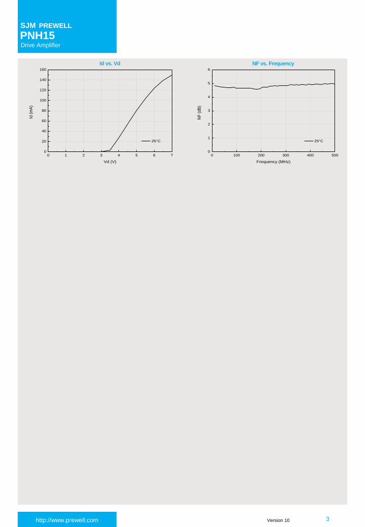
0 100 200 300 400 5000
1
2
3
4
5
6
NF
(d
B)
Frequency (MHz)
25°C
0 1 2 3 4 5 6 70
20
40
60
80
100
120
140
160
Id (
mA
)
Vd (V)
25°C
Id vs. Vd NF vs. Frequency

http://www.prewell.com 4
Drive Amplifier
SJM PREWELL
PNH15
Version 10
800 850 900 950 10005
10
15
20
25
30
P1dB
(dB
m)
Frequency (MHz)
25°C
-40°C
85°C
5 7 9 11 13 1525
30
35
40
45
50
OIP
3 (
dB
m)
Frequency (MHz)
OIP3 @ 900MHz
800 850 900 950 100025
30
35
40
45
50
OIP
3 (
dB
m)
Frequency (MHz)
25°C
-40°C
85°C
800 850 900 950 1000-35
-30
-25
-20
-15
-10
S2
2 (
dB
)
Frequency (MHz)
25°C
-40°C
85°C
800 850 900 950 1000-40
-35
-30
-25
-20
-15
-10
S1
1 (
dB
)
Frequency (MHz)
25°C
-40°C
85°C
800 850 900 950 100016
18
20
22
24
26
S2
1 (
dB
)
Frequency (MHz)
25°C
-40°C
85°C
Parameters UnitsFrequency (MHz)
900
S21 dB 20.5
S11 dB -24
S22 dB -16
P1dB dBm 23.6
OIP3 @ 9dBm dBm 39.6
NF dB 4.9
Typical RF Performance for 900MHz Tuned Application Circuit (5V / 78mA)
Gain vs. Frequency Input Return Loss
Output Return Loss OIP3 vs. Frequency
OIP3 vs. Output Power P1dB vs. Frequency
RF IN RF OUT20pF 20pF
10nH
20pF
1uF
5V
2.7nH
4pF
5.1Ω

http://www.prewell.com 5
Drive Amplifier
SJM PREWELL
PNH15
Version 10
2 5 8 11 14 17-70
-65
-60
-55
-50
-45
-40
-35
-30
LT
E (
dB
c)
Output Power (dBm)
25°C
-40°C
85°C
3 6 9 12 15 18
-66
-60
-54
-48
-42
-36
-30
AC
LR
(d
Bc)
Output Channel Power (dBm)
25°C
-40°C
85°C
-20 -15 -10 -5 0 5 100
5
10
15
20
25
30
Ou
tput
Po
we
r (d
Bm
) / G
ain
(d
B)
Input Power (dBm)
Gain
Output Power
800 850 900 950 10002
3
4
5
6
7
NF
(d
B)
Frequency (MHz)
25°C
Output Power / Gain vs. Input Power @ 900MHz
1FA W-CDMA ACLR vs. Channel Power3GPP W-CDMA 1FA, Test Model5 + w/8HSPDSCH, 5MHz offset, 900MHz
NF vs. Frequency
LTE vs. Output Power @ 900MHzDL20M_E31.WFM 1FA, 20MHz offset

http://www.prewell.com 6
Drive Amplifier
SJM PREWELL
PNH15
Version 10
1800 1850 1900 1950 2000-30
-25
-20
-15
-10
-5
0
S2
2 (
dB
)
Frequency (MHz)
25°C
-40°C
85°C
1800 1850 1900 1950 20005
10
15
20
25
30
35
P1dB
(dB
m)
Frequency (MHz)
25°C
-40°C
85°C
5 7 9 11 13 1520
25
30
35
40
45
50
OIP
3 (
dB
m)
Output Power (dBm)
OIP3 @ 1900MHz
1800 1850 1900 1950 200020
25
30
35
40
45
50
OIP
3 (
dB
m)
Frequency (MHz)
25°C
-40°C
85°C
1800 1850 1900 1950 2000-30
-25
-20
-15
-10
-5
0
S1
1 (
dB
)
Frequency (MHz)
25°C
-40°C
85°C
1800 1850 1900 1950 200013
14
15
16
17
18
19
S2
1 (
dB
)
Frequency (MHz)
25°C
-40°C
85°C
Parameters UnitsFrequency (MHz)
1900
S21 dB 16.6
S11 dB -18.9
S22 dB -10.6
P1dB dBm 24.5
OIP3 @ 9dBm dBm 38.5
NF dB 3.4
Typical RF Performance for 1900MHz Tuned Application Circuit (5V / 78mA)
RF IN RF OUT100pF 100pF
6.8nH
100pF
1uF
5V
2.5mm
1.8pF 0.75pF
5.0mm
Gain vs. Frequency Input Return Loss
Output Return Loss OIP3 vs. Frequency
OIP3 vs. Output Power P1dB vs. Frequency

http://www.prewell.com 7
Drive Amplifier
SJM PREWELL
PNH15
Version 10
4 7 10 13 16 19-70
-65
-60
-55
-50
-45
-40
-35
-30
AC
LR
(d
Bc)
Output Power (dBm)
25°C
-40°C
85°C
3 6 9 12 15 18-60
-55
-50
-45
-40
-35
-30
AC
LR
(d
Bc)
Output Channel Power (dBm)
25°C
-40°C
85°C
2 5 8 11 14 17-65
-60
-55
-50
-45
-40
-35
-30
AC
LR
(d
Bc)
Output Channel Power (dBm)
25°C
-40°C
85°C
5 8 11 14 17 20-70
-65
-60
-55
-50
-45
-40
-35
-30
AC
LR
(d
Bc)
Output Channel Power (dBm)
25°C
-40°C
85°C
-15 -10 -5 0 5 10 150
5
10
15
20
25
30
Ou
tput
Po
we
r (d
Bm
) / G
ain
(d
B)
Input Power (dBm)
Gain
Output Power
1800 1850 1900 1950 20000
1
2
3
4
5
6
NF
(d
B)
Frequency (MHz)
25°C
Output Power / Gain vs. Input Power @ 1900MHz
1FA W-CDMA ACLR vs. Channel Power3GPP W-CDMA 1FA, Test Model5 + w/8HSPDSCH, 5MHz offset, 1850MHz
4FA W-CDMA ACLR vs. Channel Power3GPP W-CDMA 4FA, Test Model5 + w/8HSPDSCH, 5MHz offset, 1850MHz
6FA W-CDMA ACLR vs. Channel Power3GPP W-CDMA 6FA, Test Model5 + w/8HSPDSCH, 5MHz offset, 1850MHz
NF vs. Frequency
LTE vs. Output Power @ 1850MHzDL20M_E31.WFM 1FA, 20MHz offset

http://www.prewell.com 8
Drive Amplifier
SJM PREWELL
PNH15
Version 10
2050 2100 2150 2200 22505
10
15
20
25
30
35
P1dB
(dB
m)
Frequency (MHz)
25°C
-40°C
85°C
5 7 9 11 13 1520
25
30
35
40
45
50
OIP
3 (
dB
m)
Output Power (dBm)
OIP3 @ 2140MHz
2050 2100 2150 2200 225020
25
30
35
40
45
50
OIP
3 (
dB
m)
Frequency (MHz)
25°C
-40°C
85°C
2050 2100 2150 2200 2250-30
-25
-20
-15
-10
-5
0
S2
2 (
dB
)
Frequency (MHz)
25°C
-40°C
85°C
2050 2100 2150 2200 2250-30
-25
-20
-15
-10
-5
0
S1
1 (
dB
)
Frequency (MHz)
25°C
-40°C
85°C
2050 2100 2150 2200 22500
5
10
15
20
25
30
S2
1 (
dB
)
Frequency (MHz)
25°C
-40°C
85°C
Parameters UnitsFrequency (MHz)
2140
S21 dB 15.4
S11 dB -13
S22 dB -13
P1dB dBm 24.2
OIP3 @ 9dBm dBm 38
NF dB 3.5
Typical RF Performance for 2140MHz Tuned Application Circuit (5V / 78mA)
RF IN RF OUT100pF 100pF
6.8nH
100pF
1uF
5V
2.5mm
1.5pF 1.0pF
5.0mm
Gain vs. Frequency Input Return Loss
Output Return Loss OIP3 vs. Frequency
OIP3 vs. Output Power P1dB vs. Frequency

http://www.prewell.com 9
Drive Amplifier
SJM PREWELL
PNH15
Version 10
-15 -10 -5 0 5 10 150
5
10
15
20
25
30
Ou
tput
Po
we
r (d
Bm
) / G
ain
(d
B)
Input Power (dBm)
Gain
Output Power
1 4 7 10 13 16-60
-55
-50
-45
-40
-35
AC
LR
(dB
c)
Output Channel Power (dBm)
25°C
-40°C
85°C
1 4 7 10 13 16-65
-60
-55
-50
-45
-40
-35
AC
LR
(d
Bc)
Output Channel Power (dBm)
25°C
-40°C
85°C
4 7 10 13 16-70
-65
-60
-55
-50
-45
-40
-35
AC
LR
(d
Bc)
Output Channel Power (dBm)
25°C
-40°C
85°C
2050 2100 2150 2200 22500
1
2
3
4
5
6
NF
(d
B)
Frequency (MHz)
25°C
Output Power / Gain vs. Input Power @ 2140MHz
1FA W-CDMA ACLR vs. Channel Power3GPP W-CDMA 1FA, Test Model5 + w/8HSPDSCH, 5MHz offset, 2140MHz
4FA W-CDMA ACLR vs. Channel Power3GPP W-CDMA 4FA, Test Model5 + w/8HSPDSCH, 5MHz offset, 2140MHz
6FA W-CDMA ACLR vs. Channel Power3GPP W-CDMA 6FA, Test Model5 + w/8HSPDSCH, 5MHz offset, 2140MHz
NF vs. Frequency
http://www.prewell.com 10
Drive Amplifier
SJM PREWELL
PNH15
Version 10
2500 2550 2600 2650 27001
2
3
4
5
6
NF
(dB
)
Frequency (MHz)
25°C
2500 2550 2600 2650 27005
10
15
20
25
30
P1dB
(dB
m)
Frequency (MHz)
25°C
-40°C
85°C
2500 2550 2600 2650 270020
25
30
35
40
45
50
OIP
3 (
dB
m)
Frequency (MHz)
25°C
-40°C
85°C
2500 2550 2600 2650 2700-35
-30
-25
-20
-15
-10
-5
S2
2 (
dB
)
Frequency (MHz)
25°C
-40°C
85°C
2500 2550 2600 2650 2700-25
-20
-15
-10
-5
0
S1
1 (
dB
)
Frequency (MHz)
25°C
-40°C
85°C
2500 2550 2600 2650 27000
5
10
15
20
25
S2
1 (
dB
)
Frequency (MHz)
25°C
-40°C
85°C
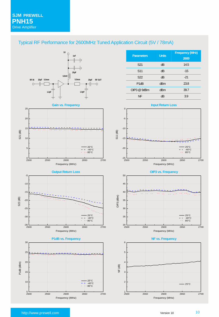
Parameters UnitsFrequency (MHz)
2600
S21 dB 14.5
S11 dB -15
S22 dB -21
P1dB dBm 23.8
OIP3 @ 9dBm dBm 39.7
NF dB 3.9
Typical RF Performance for 2600MHz Tuned Application Circuit (5V / 78mA)
RF IN RF OUT20pF 20pF
6.8nH
20pF
1uF
5V
5.0mm
1.2pF 1.0pF
5.0mm
Gain vs. Frequency Input Return Loss
Output Return Loss OIP3 vs. Frequency
P1dB vs. Frequency NF vs. Frequency

http://www.prewell.com 11
Drive Amplifier
SJM PREWELL
PNH15
Version 10
1 4 7 10 13 16-60
-55
-50
-45
-40
-35
-30
AC
LR
(d
Bc)
Output Channel Power (dBm)
25°C
-40°C
85°C
3 6 9 12 15 18-70
-65
-60
-55
-50
-45
-40
-35
-30
LT
E (
dB
c)
Output Power (dBm)
25°C
-40°C
85°C
6FA W-CDMA ACLR vs. Channel Power3GPP W-CDMA 6FA, Test Model5 + w/8HSPDSCH, 5MHz offset, 2650MHz
LTE vs. Output Power @ 2650MHzDL20M_E31.WFM 1FA, 20MHz offset
http://www.prewell.com 12
Drive Amplifier
SJM PREWELL
PNH15
Version 10
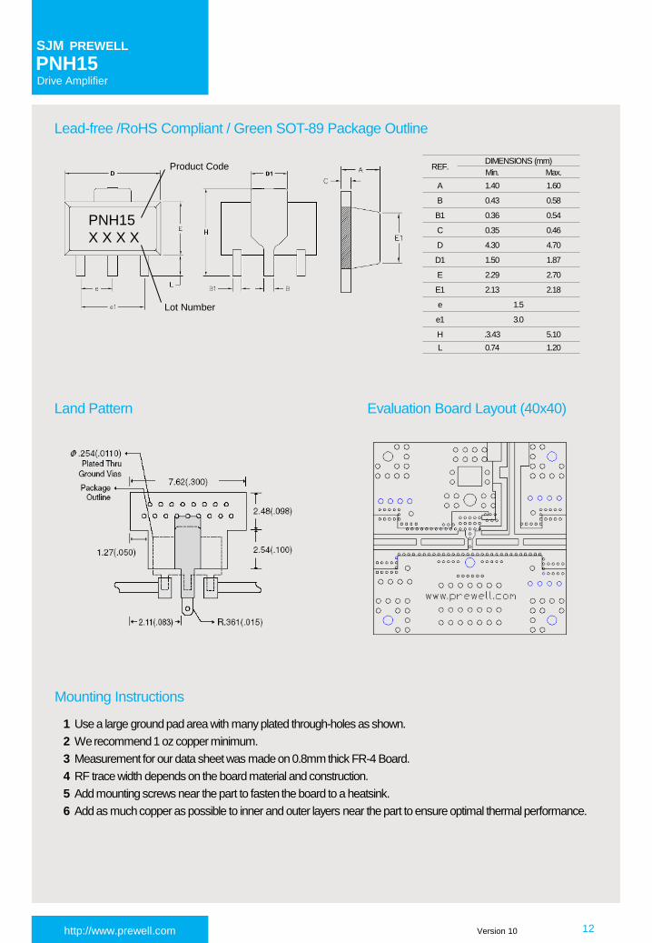
Evaluation Board Layout (40x40)
Lead-free /RoHS Compliant / Green SOT-89 Package Outline
Land Pattern
Mounting Instructions
1 Use a large ground pad area with many plated through-holes as shown.
2 We recommend 1 oz copper minimum.
3 Measurement for our data sheet was made on 0.8mm thick FR-4 Board.
4 RF trace width depends on the board material and construction.
5 Add mounting screws near the part to fasten the board to a heatsink.
6 Add as much copper as possible to inner and outer layers near the part to ensure optimal thermal performance.
REF.DIMENSIONS (mm)
Min. Max.
A 1.40 1.60
B 0.43 0.58
B1 0.36 0.54
C 0.35 0.46
D 4.30 4.70
D1 1.50 1.87
E 2.29 2.70
E1 2.13 2.18
e 1.5
e1 3.0
H .3.43 5.10
L 0.74 1.20
Product Code
Lot Number
PNH15
X X X X

http://www.prewell.com 13
Drive Amplifier
SJM PREWELL
PNH15
Version 10
SJMPREWELL reserves the right to make changes to any products herein or to discontinue any product at any time without notice. While product specifications have
been thoroughly examined for reliability, SJMPREWELL recommends buyers to verify that the information they are using is accurate before ordering. SJMPREWELL
does not assume any liability for the suitability of its products for any particular purpose, and disclaims any and all liabi lity, including without limitation consequential or
incidental damages. SJMPREWELL products are not intended for use in life support equipment or application where malfunction of the product can be expected to
result in personal injury or death. Buyer uses or sells such products for any such unintended or unauthorized application, buyer shall indemnify, protect SJM PREWELL
and its directors, officers, stockholders, employees, representatives and distributors harmless against any and all claims arising out of such unauthorized use.
Contact Information For the latest specifications, additional product information, worldwide sales and distribution locations:
KOREA Headquarter Office
WEB : www.prewell.com
TEL. : +82 31 689 5510 / Fax. +82 31 689 5507
Email : [email protected]