Embed Size (px)
Citation preview

CranesCranesCranesCranes
AP10: Cabling and Wiring AP10: Cabling and Wiring AP10: Cabling and Wiring AP10: Cabling and Wiring Guidelines SINAMICSGuidelines SINAMICSGuidelines SINAMICSGuidelines SINAMICS
Product InformationProduct InformationProduct InformationProduct Information
11/20111/20111/20111/2013333
ForewordForewordForewordForeword
IntroductionIntroductionIntroductionIntroduction 1111
Selection of load side Selection of load side Selection of load side Selection of load side componentscomponentscomponentscomponents
2222
Sizing of cable cross sectionSizing of cable cross sectionSizing of cable cross sectionSizing of cable cross section 3333
Power cable selectionPower cable selectionPower cable selectionPower cable selection 4444
Installation of control cablesInstallation of control cablesInstallation of control cablesInstallation of control cables 5555
Busbar conneBusbar conneBusbar conneBusbar connections ctions ctions ctions (including cable connection)(including cable connection)(including cable connection)(including cable connection)
6666
Installation of eInstallation of eInstallation of eInstallation of e----chainchainchainchain®®®® and and and and chainflexchainflexchainflexchainflex®®®® cables cables cables cables
7777
AppendixAppendixAppendixAppendix AAAA
Legal informationLegal informationLegal informationLegal information Warning notice systemWarning notice systemWarning notice systemWarning notice system
This manual contains notices you have to observe in order to ensure your personal safety, as well as to prevent damage to property. The notices referring to your personal safety are highlighted in the manual by a safety alert symbol, notices referring only to property damage have no safety alert symbol. These notices shown below are graded according to the degree of danger.
! DANGERDANGERDANGERDANGER
indicates that death or severe personal injury willwillwillwill result if proper precautions are not taken.
! WARNINGWARNINGWARNINGWARNING
indicates that death or severe personal injury maymaymaymay result if proper precautions are not taken.
! CAUTCAUTCAUTCAUTIONIONIONION
with a safety alert symbol, indicates that minor personal injury can result if proper precautions are not taken.
CAUTIONCAUTIONCAUTIONCAUTION without a safety alert symbol, indicates that property damage can result if proper precautions are not taken.
NOTICENOTICENOTICENOTICE indicates that an unintended result or situation can occur if the relevant information is not taken into account.
If more than one degree of danger is present, the warning notice representing the highest degree of danger will be used. A notice warning of injury to persons with a safety alert symbol may also include a warning relating to property damage.
Qualified PersonnelQualified PersonnelQualified PersonnelQualified Personnel The product/system described in this documentation may be operated only by personnel qualifiedpersonnel qualifiedpersonnel qualifiedpersonnel qualified for the specific task in accordance with the relevant documentation, in particular its warning notices and safety instructions. Qualified personnel are those who, based on their training and experience, are capable of identifying risks and avoiding potential hazards when working with these products/systems.
Proper use of Proper use of Proper use of Proper use of SiemensSiemensSiemensSiemens products products products products Note the following:
! WARNINGWARNINGWARNINGWARNING
Siemens products may only be used for the applications described in the catalog and in the relevant technical documentation. If products and components from other manufacturers are used, these must be recommended or approved by Siemens. Proper transport, storage, installation, assembly, commissioning, operation and maintenance are required to ensure that the products operate safely and without any problems. The permissible ambient conditions must be complied with. The information in the relevant documentation must be observed.
TrademarksTrademarksTrademarksTrademarks All names identified by ® are registered trademarks of Siemens AG. The remaining trademarks in this publication may be trademarks whose use by third parties for their own purposes could violate the rights of the owner.
Disclaimer of LiabilityDisclaimer of LiabilityDisclaimer of LiabilityDisclaimer of Liability We have reviewed the contents of this publication to ensure consistency with the hardware and software described. Since variance cannot be precluded entirely, we cannot guarantee full consistency. However, the information in this publication is reviewed regularly and any necessary corrections are included in subsequent editions.
Siemens AG Industry Sector Postfach 48 48 90026 NÜRNBERG GERMANY
Ⓟ 11/2013
Copyright © Siemens AG 2013. Technical data subject to change

AP10: Cabling and Wiring Guidelines SINAMICS
Product Information, 11/2013 3
ForewordForewordForewordForeword
General NotesGeneral NotesGeneral NotesGeneral Notes
NoteNoteNoteNote
The standard applications are not binding and do not claim to be complete regarding the circuits shown, equipping and any eventuality. The standard applications do not represent customer-specific solutions. They are only intended to provide support for typical applications. You are responsible in ensuring that the described products are correctly used. These standard applications do not relieve you of the responsibility in safely and professionally using, installing, operating and servicing equipment. When using these standard applications, you recognize that we cannot be made liable for any damage/claims beyond the liability clause described. We reserve the right to make changes to these standard applications at any time without prior notice. If there are any deviations between the recommendations provided in these standard applications and other Siemens publications – e. g. catalogs – then the contents of the other documents have priority.
Guarantee, Liability and SupportGuarantee, Liability and SupportGuarantee, Liability and SupportGuarantee, Liability and Support
If the application is provided free of charge the following shall apply: We shall not be liable for the information contained in this document.
Any and all further rights and remedies against Siemens AG for whatsoever legal reason, shall be excluded; this shall refer in particular to claims for loss of production, loss of use, loss of orders or profit and other direct, indirect or consequential damage.
The aforesaid shall not apply if liability is mandatory, e. g. in accordance with the Product Liability Act, in cases of intent, gross negligence by directors and officers of Siemens AG or in the case of willful hiding of a defect.
These limitations of liability shall also apply for the benefit of the Siemens AG's subcontractors, suppliers, agents, directors, officers and employees.
This Contract shall be subject to German law if customer’s place of business is in Germany.
If customer’s place of business is outside of Germany the Contract shall be subject to Swiss law. The application of the UN Convention on Contracts for the International Sale of Goods (CISG) shall be excluded.
If the application is provided in return for payment the alternative shall apply which fits the respective business case:

Introduction
AP10: Cabling and Wiring Guidelines SINAMICS 4 Product Information, 11/2013
● Alternative 1: (internal business)
If not explicitly stated otherwise below, the "Terms and Conditions for Deliveries and Services for Siemens Internal Transactions", valid at the time of sale, are applicable.
● Alternative 2: (domestic business of Siemens AG)
If not explicitly stated otherwise below, the "General License Conditions for Software Products for Automation and Drives for Customers with a Seat or registered Office in Germany", valid at the time of sale, are applicable.
● Alternative 3: (direct export business of Siemens AG)
If not explicitly stated otherwise below, the "General License Conditions for Software Products for Automation and Drives for Customers with a Seat or Registered Office outside of Germany", valid at the time of sale, are applicable.
It is not permissible to transfer or copy these standard applications or excerpts of them in unmodified form without first having prior explicit authorization from Siemens Industry Sector in writing.
Export Procedure IndicatorExport Procedure IndicatorExport Procedure IndicatorExport Procedure Indicator
AL: N
ECCN: N
BackgroundBackgroundBackgroundBackground Siemens supplies electrical components such as SIMATIC S7 programmable logic controllers, SINAMICS frequency converters, SINAMICS infeed and regenerative units and induction motors as components for installation on cranes in the harbour and other industries. Safe and reliable performance of the electrical components without disturbance or premature failure of electronic components depends on adequate installation and wiring practices. The following chapters describe in detail cabling recommendations by Siemens.
Particularly noteworthy are aspects covered in the international standard IEC 60204-32 providing requirements and recommendations relating to the electrical equipment of hoisting machines so as to promote safety of persons and property, consistency of control response and ease of maintenance.
IEC 60204IEC 60204IEC 60204IEC 60204----32323232 Safety of machinery – Electrical equipment of machines –
Part 32: Requirements for hoisting machines
EN 954EN 954EN 954EN 954----1111 Safety of machinery – Safety-related parts of control systems - Part 1: General principles for design
DIN VDE DIN VDE DIN VDE DIN VDE 0660066006600660 Part 12 – Protective conductor terminals EN 55011EN 55011EN 55011EN 55011 Limits and methods of measurement of radio disturbance
characteristics of industrial, scientific and medical (ISM) radio-frequency equipment
EN 61800EN 61800EN 61800EN 61800----3333 EMC product standard including special test methods for electric drive units

Introduction
AP10: Cabling and Wiring Guidelines SINAMICS Product Information, 11/2013 5
89/336/EWG89/336/EWG89/336/EWG89/336/EWG COUNCIL DIRECTIVE of 3 May 1989 on the approximation of the laws of the Member States relating to electromagnetic compatibility
73/23/EWG73/23/EWG73/23/EWG73/23/EWG Council Directive of 19 February 1973 on the harmonization of the laws of Member States relating to electrical equipment designed for use within certain voltage limits
6SE70876SE70876SE70876SE7087----6QX606QX606QX606QX60 Masterdrives Compendium Vector Control 1998 6SE70876SE70876SE70876SE7087----6CX876CX876CX876CX87----8CE08CE08CE08CE0 Installation Instructions for EMC Correct Installation of
Drives Igus chainflex catIgus chainflex catIgus chainflex catIgus chainflex catalog, latalog, latalog, latalog, latestestestest versionversionversionversion Prysmian (Pirelli) catalog BU IS Prysmian (Pirelli) catalog BU IS Prysmian (Pirelli) catalog BU IS Prysmian (Pirelli) catalog BU IS 2.1 × 20002.1 × 20002.1 × 20002.1 × 2000
Flexible Electric Cables especially for e-chains Flexible Electric Cables
SINAMICS catalogue D21.3SINAMICS catalogue D21.3SINAMICS catalogue D21.3SINAMICS catalogue D21.3 SINAMICS S120 chassis / cabinet modules SINAMICS Engineering ManualSINAMICS Engineering ManualSINAMICS Engineering ManualSINAMICS Engineering Manual SINAMICS G130, G150, S120 Chassis, S120 Cabinet
Modules, S150 IEEE Transactions on Industrial IEEE Transactions on Industrial IEEE Transactions on Industrial IEEE Transactions on Industrial Applications Applications Applications Applications (Vol.(Vol.(Vol.(Vol. 42, No.42, No.42, No.42, No. 4 July/August 4 July/August 4 July/August 4 July/August 2006)2006)2006)2006)
Article by Annette Muetze and Andreas Binder
The implementation of these recommendations is no substitute for a risk assessment of the crane which needs to be made by the crane builder.

Introduction
AP10: Cabling and Wiring Guidelines SINAMICS 6 Product Information, 11/2013
Table of contentsTable of contentsTable of contentsTable of contents
1111 IntroductionIntroductionIntroductionIntroduction.................................................................................................................................................................................................................................................................................................................................................................................................................................................................................................................................................................................... 7777
1.1 High frequency disturbance .......................................................................................................... 7
1.2 Long motor cables......................................................................................................................... 8
1.3 Common-mode oscillation........................................................................................................... 12
1.4 Bearing current............................................................................................................................ 13
2222 Selection of load side componentsSelection of load side componentsSelection of load side componentsSelection of load side components ................................................................................................................................................................................................................................................................................................................................................................................................................................ 15151515
2.1 Maximum cable length, no output reactor................................................................................... 15
2.2 Maximum cable length and output reactor.................................................................................. 16 2.2.1 Voltage-limiting du/dt filters ......................................................................................................... 17 2.2.2 Sine filters.................................................................................................................................... 20
3333 Sizing of cable cross sectionSizing of cable cross sectionSizing of cable cross sectionSizing of cable cross section .................................................................................................................................................................................................................................................................................................................................................................................................................................................................... 22222222
3.1 Conductors .................................................................................................................................. 22
3.2 Protective conductor ................................................................................................................... 22
4444 Power cable selectionPower cable selectionPower cable selectionPower cable selection ............................................................................................................................................................................................................................................................................................................................................................................................................................................................................................................ 24242424
4.1 Types of power cable .................................................................................................................. 24
4.2 Insulation material used for power cables................................................................................... 25
4.3 Installation guidelines.................................................................................................................. 25 4.3.1 Grounding and high-frequency equipotential bonding ................................................................ 27 4.3.2 Wiring guidelines in accordance to EMC rules ........................................................................... 29 4.3.3 Digital signals / encoder .............................................................................................................. 32 4.3.4 EMC-compliant cable routing on the plant side on cable racks and in cable ducts.................... 34 4.3.5 Wiring requirements as per IEC 60204-32.................................................................................. 36 4.3.6 Wiring practices to be avoided.................................................................................................... 39 4.3.7 Best practices for screened power cable termination ................................................................. 41
5555 Installation of control cablesInstallation of control cablesInstallation of control cablesInstallation of control cables ........................................................................................................................................................................................................................................................................................................................................................................................................................................................................ 47474747
5.1 Installation of PROFIBUS cables ................................................................................................ 47
5.2 Installation of encoder cables...................................................................................................... 49
6666 Busbar connections (including cable connection)Busbar connections (including cable connection)Busbar connections (including cable connection)Busbar connections (including cable connection) ........................................................................................................................................................................................................................................................................................................................................ 53535353
7777 Installation of eInstallation of eInstallation of eInstallation of e----chainchainchainchain®®®® and chainflex and chainflex and chainflex and chainflex®®®® cables cables cables cables ................................................................................................................................................................................................................................................................................................................................................................ 54545454
A.1 Contact ........................................................................................................................................ 61

Introduction
AP10: Cabling and Wiring Guidelines SINAMICS Product Information, 11/2013 7
IntroductionIntroductionIntroductionIntroduction 1111
Variable speed drives have become an integral component of the electrical control system for cranes. The installation of variable speed drives on cranes with increasing rated load and crane size has become a technical challenge. The following recommendations are meant to help the crane builder in carrying out the electrical installation and cabling in a way that latest aspects of variable speed drives parasitic effects are covered.
1.11.11.11.1 High frequency disturbanceHigh frequency disturbanceHigh frequency disturbanceHigh frequency disturbance Variable-speed drives have advantages and disadvantages. One of the disadvantages is the high switching frequency of the semiconductor (IGBT) which can cause disturbances to other components.
Sinamics frequency converters (motor modules) operate with a voltage-source DC link. In order to keep the power losses as low as possible the inverter switches the DC link voltage to the motor winding in the form of voltage blocks. A reasonably sinusoidal current flows into the motor.
Figure 1-1 Block diagram of a PWM converter with voltage-source DC link
Introduction 1.2 Long motor cables
AP10: Cabling and Wiring Guidelines SINAMICS 8 Product Information, 11/2013
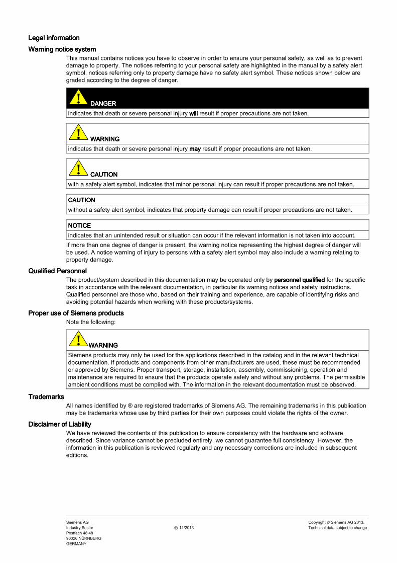
The described mode of operation in conjunction with high-performance semiconductor switching elements has made it possible to develop compact frequency converters which now play a vital role in drive technology.
However, due to the fast switching a pulse-type noise current flows to ground through parasitic capacitances CP at each switching edge. Parasitic capacitances exist between the motor cable and ground and also within the motor.
Figure 1-2 Block diagram showing output voltage V and fault current Is
The source of the earth current IS is the inverter, thus this earth current must also flow back to the inverter. Impedance ZN and ground impedance ZE act in the return flow path. Impedance ZN forms parasitic capacitances between the supply cable and ground which is connected in parallel with the impedance (between phase and ground) of the supply transformer. The noise current itself and the voltage drops across ZN and ZE caused by the noise current can also affect other electrical units. Therefore, variable-speed drives generate high-frequency noise currents.
EMC stands for "Electromagnetic Compatibility" and, in accordance with the EMC Law §2(7), it defines "the capability of a unit to operate satisfactorily in an electromagnetic environment, without itself causing electromagnetic disturbances which would be unacceptable for other electrical units in this environment".
1.21.21.21.2 Long motor cablesLong motor cablesLong motor cablesLong motor cables Effect of crane mechanical configurations on the length of the electrical cables of a Ship-to-Shore (STS) type of crane:
Introduction 1.2 Long motor cables
AP10: Cabling and Wiring Guidelines SINAMICS Product Information, 11/2013 9
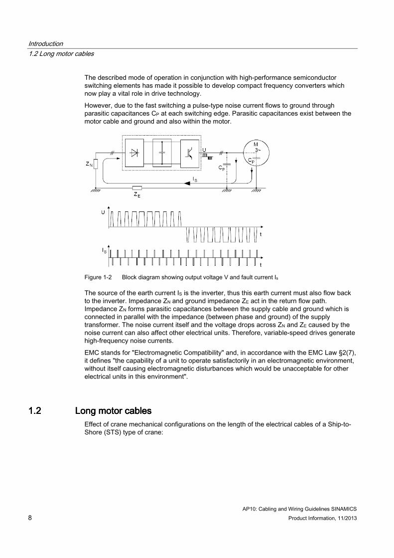
Machinery on trolley Machinery on trolley Machinery on trolley Machinery on trolley (MOT)(MOT)(MOT)(MOT)
Positive:Positive:Positive:Positive:
● Shorter wire-ropes for hoist
● No wire-ropes for trolley
Negative:Negative:Negative:Negative:
● Long electrical cables for hoist motors
● Long electrical cables for trolley motors
● Space constraints for hoist motors
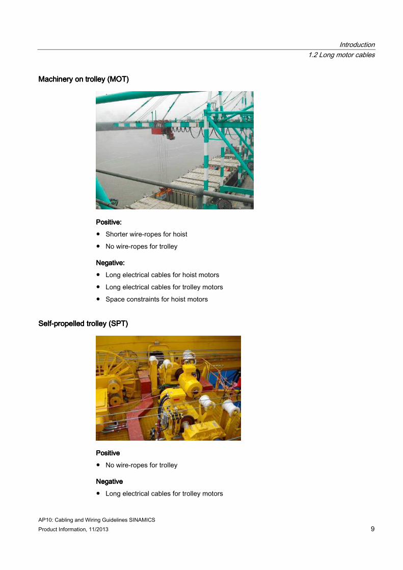
SelfSelfSelfSelf----propelled trolley (SPT)propelled trolley (SPT)propelled trolley (SPT)propelled trolley (SPT)
PositivePositivePositivePositive
● No wire-ropes for trolley
NegativeNegativeNegativeNegative
● Long electrical cables for trolley motors
Introduction 1.2 Long motor cables
AP10: Cabling and Wiring Guidelines SINAMICS 10 Product Information, 11/2013
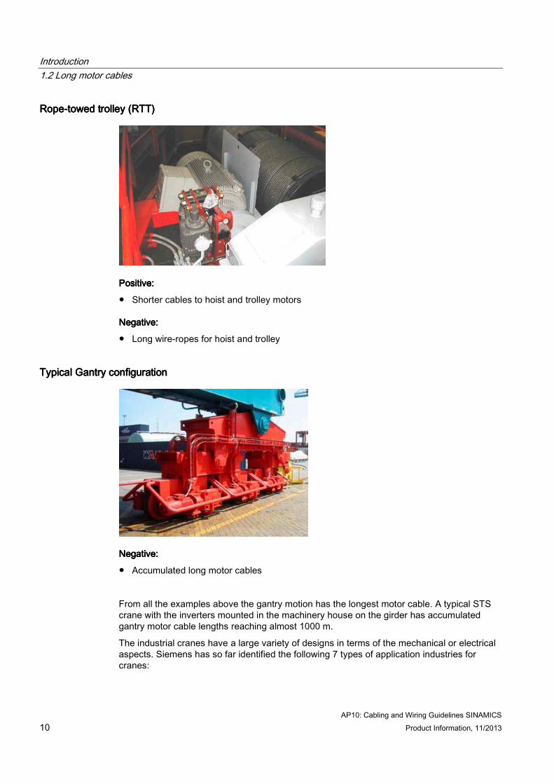
RopeRopeRopeRope----towed trolley (RTT)towed trolley (RTT)towed trolley (RTT)towed trolley (RTT)
Positive:Positive:Positive:Positive:
● Shorter cables to hoist and trolley motors
Negative:Negative:Negative:Negative:
● Long wire-ropes for hoist and trolley
Typical Gantry configurationTypical Gantry configurationTypical Gantry configurationTypical Gantry configuration
Negative:Negative:Negative:Negative:
● Accumulated long motor cables
From all the examples above the gantry motion has the longest motor cable. A typical STS crane with the inverters mounted in the machinery house on the girder has accumulated gantry motor cable lengths reaching almost 1000 m.
The industrial cranes have a large variety of designs in terms of the mechanical or electrical aspects. Siemens has so far identified the following 7 types of application industries for cranes:
Introduction 1.2 Long motor cables
AP10: Cabling and Wiring Guidelines SINAMICS Product Information, 11/2013 11
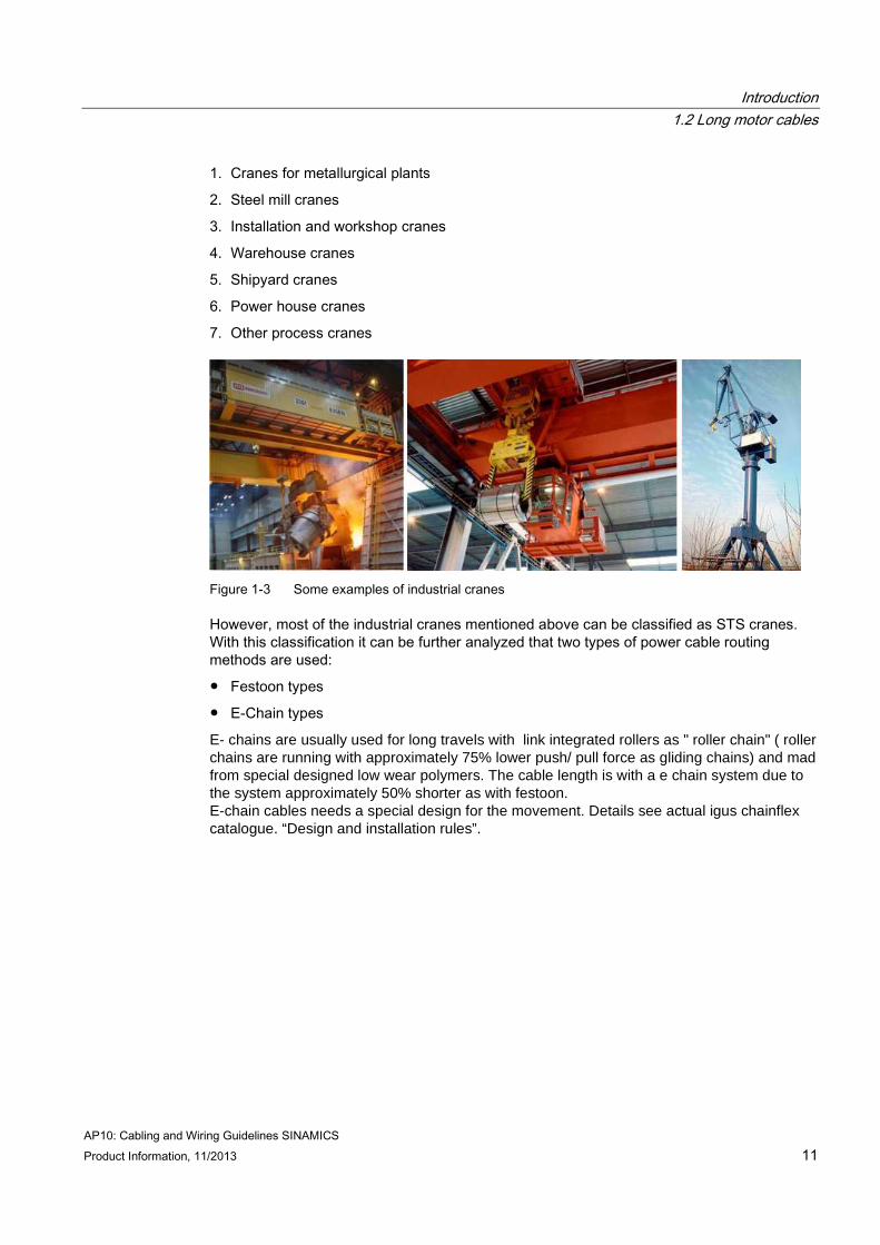
1. Cranes for metallurgical plants
2. Steel mill cranes
3. Installation and workshop cranes
4. Warehouse cranes
5. Shipyard cranes
6. Power house cranes
7. Other process cranes
Figure 1-3 Some examples of industrial cranes
However, most of the industrial cranes mentioned above can be classified as STS cranes. With this classification it can be further analyzed that two types of power cable routing methods are used:
● Festoon types
● E-Chain types
E- chains are usually used for long travels with link integrated rollers as " roller chain" ( roller chains are running with approximately 75% lower push/ pull force as gliding chains) and mad from special designed low wear polymers. The cable length is with a e chain system due to the system approximately 50% shorter as with festoon. E-chain cables needs a special design for the movement. Details see actual igus chainflex catalogue. “Design and installation rules”.

Introduction 1.3 Common-mode oscillation
AP10: Cabling and Wiring Guidelines SINAMICS 12 Product Information, 11/2013
1.31.31.31.3 CommonCommonCommonCommon----mode oscillationmode oscillationmode oscillationmode oscillation On large cranes with long motor feeder cables (e. g. SPT and MOT configurations) in combination with pulsed line-side converters, a common-mode oscillation may occur that could lead to excessive phase-to-ground voltage stress on the motors.
Figure 1-4 Principal circuit for common-mode oscillation
Engineering of the drive system has to consider carefully the entire drive train, comprising
● the medium voltage transformer
● the drive system with line-side converters and inverters on the common DC bus
● the motor with the insulation class
● the cabling between the different components

Introduction 1.4 Bearing current
AP10: Cabling and Wiring Guidelines SINAMICS Product Information, 11/2013 13
1.41.41.41.4 Bearing currentBearing currentBearing currentBearing current
Under certain circumstances it is possible that bearing current can also occur in drives in crane applications operated on a frequency converter.
Through the arising bearing current there is the danger of abrasion of components of the bearing shell of the engine mounts that can accumulate in the lubricating film and lead to further wear of the engine mounts.
Figure 1-5 Types of bearing current in a typical crane system
The figure above shows the fundamental bearing currents which can lead to premature bearing failures and also possible encoder failures (depending on the insulation of the encoder from the bearing). In the following you find a brief description of the various bearing currents shown above:
Circular currentCircular currentCircular currentCircular current
High frequency leakage current flows between winding and housing and thus to ground which induces a high frequency shaft voltage (VShaft). Current flows from shaft to housing in one bearing and from housing back to shaft in the other bearing.
Electrostatic Discharge Machining (EDM) currentElectrostatic Discharge Machining (EDM) currentElectrostatic Discharge Machining (EDM) currentElectrostatic Discharge Machining (EDM) current
Phase-to-ground voltage (or referred to as "common mode voltage") charges the bearing capacitance. When the lubricating film on the bearing breaks down due to a high VBearing values the bearing capacitance and capacitance between winding and rotor discharges causing a high current pulse referred to as EDM.

Introduction 1.4 Bearing current
AP10: Cabling and Wiring Guidelines SINAMICS 14 Product Information, 11/2013
Rotor shaft currentRotor shaft currentRotor shaft currentRotor shaft current
When the housing of the motor is badly grounded for the purpose of high frequency currents, this causes the leakage current (due to capacitance between winding and housing) to encounter a high resistance between housing and grounded systems across. If the gearbox / driven machine of the motor is grounded more effectively then the leakage current flows in this path and can further cause damages on the gearbox or driven machine bearings apart from the motor bearings.
Extensive series of tests with realistic simulations with the respective large gear drives lead to the following results:
1. The highest bearing current occurs at lowest rotation speeds and high temperatures. At a high and stable rotation speed a bearing current develops with increasing temperature and time
2. In case the rotation speed or direction is changed, the bearing current breaks down
3. The bearing current develops over time only at constant rotation speed and reaches its maximum depending on design and drive after 50-100s.
4. At different potentials between engine and converter the highest bearing currents occur.
AP10: Cabling and Wiring Guidelines SINAMICS Product Information, 11/2013 15
Selection of load side componentsSelection of load side componentsSelection of load side componentsSelection of load side components 2222
The objective of the following chapters is to give a clear instruction on
● How to select the correct load-side components
● How to select suitable cable and type.
● How to implement correct wiring practices.
– Dimensioning of cable cross section
– Installation of power cables
– Installation of control cables
The purpose of output reactors is to limit capacitive recharging currents into the capacitance of the motor feeder cable so as to protect the IGBTs in the drive.
The selection of output reactors depends on the following parameters:
● Type of cables used (screened or unscreened; refer to table in the following chapter)
● Number of motors supplied from a converter
When a converter/inverter supplies several motors (group drive) the capacitive charge / discharge currents of the motor cables are added. The total cable length is the sum of the cable lengths for the individual motors.
2.12.12.12.1 Maximum cable length, no output reactorMaximum cable length, no output reactorMaximum cable length, no output reactorMaximum cable length, no output reactor The market of cables supplies a variety of applications and defines a myriad of criteria. However, cables can be categorized according to the following characteristics:
● Electrical (which will be looked at further in detail)
● Thermal
● Mechanical
● Chemical
● Electromagnetic capability
● Others (e. g. fire resistance etc.)
This guideline will look into the selection of cable lengths in terms of cable capacitance and the remaining characteristics of the cables as mentioned above would be in favour of the crane builder/customer.
The maximum cable lengths which can be connected to the Sinamics Motor Modules unit without reactors are specified in the following table.
If possible, insulations materials which allow especially low-capacitance cables are to be used
For example material like PP, PE, XLPE, but not rubber or PVC insulation materials.
Selection of load side components 2.2 Maximum cable length and output reactor
AP10: Cabling and Wiring Guidelines SINAMICS 16 Product Information, 11/2013
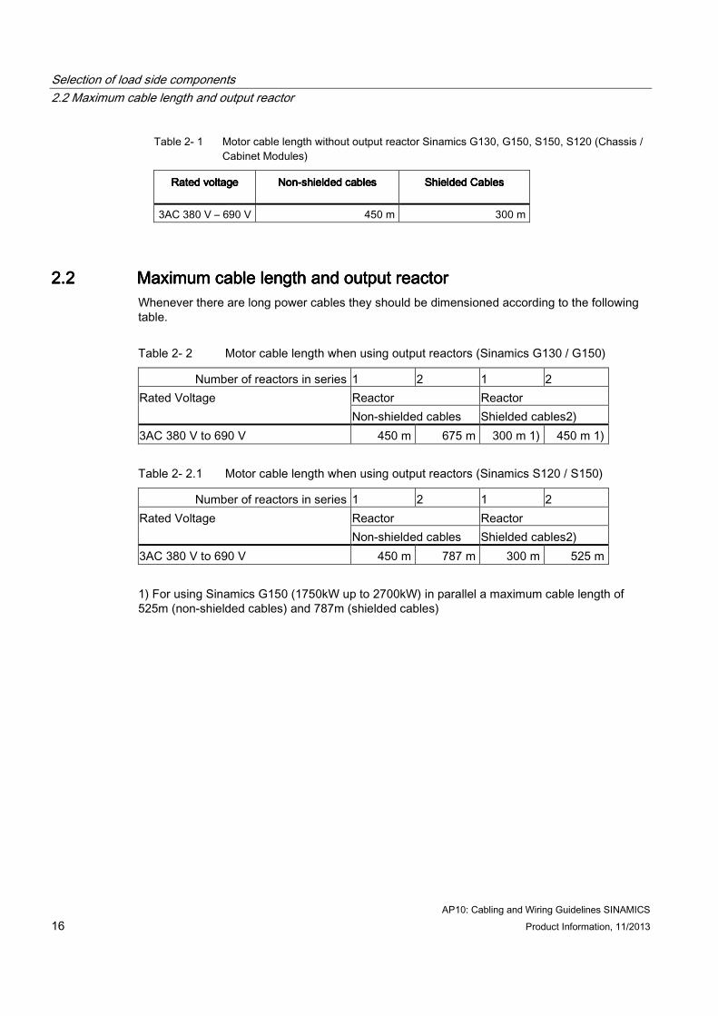
Table 2- 1 Motor cable length without output reactor Sinamics G130, G150, S150, S120 (Chassis / Cabinet Modules)
Rated voltageRated voltageRated voltageRated voltage NonNonNonNon----shielded cablesshielded cablesshielded cablesshielded cables
Shielded CablesShielded CablesShielded CablesShielded Cables
3AC 380 V – 690 V 450 m 300 m
2.22.22.22.2 Maximum cable length and output reactorMaximum cable length and output reactorMaximum cable length and output reactorMaximum cable length and output reactor Whenever there are long power cables they should be dimensioned according to the following table.
Table 2- 2 Motor cable length when using output reactors (Sinamics G130 / G150)
Number of reactors in series 1 2 1 2 Reactor Reactor Rated Voltage Non-shielded cables Shielded cables2)
3AC 380 V to 690 V 450 m 675 m 300 m 1) 450 m 1)
Table 2- 2.1 Motor cable length when using output reactors (Sinamics S120 / S150)
Number of reactors in series 1 2 1 2 Reactor Reactor Rated Voltage Non-shielded cables Shielded cables2)
3AC 380 V to 690 V 450 m 787 m 300 m 525 m
1) For using Sinamics G150 (1750kW up to 2700kW) in parallel a maximum cable length of 525m (non-shielded cables) and 787m (shielded cables)
Selection of load side components 2.2 Maximum cable length and output reactor
AP10: Cabling and Wiring Guidelines SINAMICS Product Information, 11/2013 17
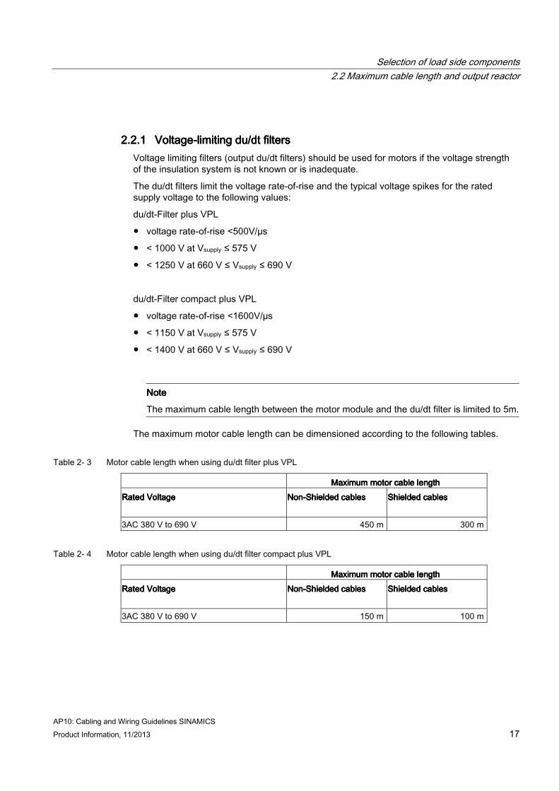
2.2.12.2.12.2.12.2.1 VoltageVoltageVoltageVoltage----limiting dlimiting dlimiting dlimiting duuuu/dt filters/dt filters/dt filters/dt filters Voltage limiting filters (output du/dt filters) should be used for motors if the voltage strength of the insulation system is not known or is inadequate.
The du/dt filters limit the voltage rate-of-rise and the typical voltage spikes for the rated supply voltage to the following values:
du/dt-Filter plus VPL
● voltage rate-of-rise <500V/µs
● < 1000 V at Vsupply ≤ 575 V
● < 1250 V at 660 V ≤ Vsupply ≤ 690 V
du/dt-Filter compact plus VPL
● voltage rate-of-rise <1600V/µs
● < 1150 V at Vsupply ≤ 575 V
● < 1400 V at 660 V ≤ Vsupply ≤ 690 V
NoteNoteNoteNote
The maximum cable length between the motor module and the du/dt filter is limited to 5m.
The maximum motor cable length can be dimensioned according to the following tables.
Table 2- 3 Motor cable length when using du/dt filter plus VPL
Maximum motor cable lengthMaximum motor cable lengthMaximum motor cable lengthMaximum motor cable length Rated VoltageRated VoltageRated VoltageRated Voltage NonNonNonNon----Shielded cablesShielded cablesShielded cablesShielded cables Shielded cablesShielded cablesShielded cablesShielded cables
3AC 380 V to 690 V 450 m 300 m
Table 2- 4 Motor cable length when using du/dt filter compact plus VPL
Maximum motor cable lengthMaximum motor cable lengthMaximum motor cable lengthMaximum motor cable length Rated VoltageRated VoltageRated VoltageRated Voltage NonNonNonNon----Shielded cablesShielded cablesShielded cablesShielded cables Shielded cablesShielded cablesShielded cablesShielded cables
3AC 380 V to 690 V 150 m 100 m
Selection of load side components 2.2 Maximum cable length and output reactor
AP10: Cabling and Wiring Guidelines SINAMICS 18 Product Information, 11/2013
NoteNoteNoteNote
The total cable length is the sum of the cable lengths connected to the individual motors. From a motor current of ≥ 120 A, single-motor drives can also be supplied with parallel cables (up to the maximum permissible cable length) in case of standard units.
NoteNoteNoteNote
The voltage limiting filters can be used up to a maximum output frequency of 150 Hz.
The permanent minimum output frequency can be 0Hz with a du/dt-Filter plus VPL and
10Hz with a du/dt-Filter compact plus VPL ( <10Hz for maximum 5min)
NoteNoteNoteNote
The du/dt filters can only be used with a motor connected.
NoteNoteNoteNote The maximum pulse frequency is limited to the double of the factory settings. Factory setting 2kHz => maximum 4kHz Factory setting 1,25kHz => maximum 2,5kHz
Selection of load side components 2.2 Maximum cable length and output reactor
AP10: Cabling and Wiring Guidelines SINAMICS Product Information, 11/2013 19
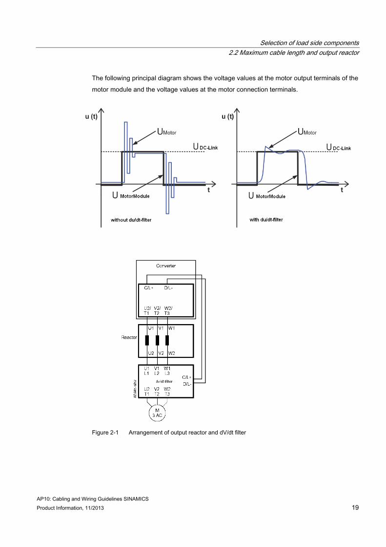
The following principal diagram shows the voltage values at the motor output terminals of the
motor module and the voltage values at the motor connection terminals.
Figure 2-1 Arrangement of output reactor and dV/dt filter
Selection of load side components 2.2 Maximum cable length and output reactor
AP10: Cabling and Wiring Guidelines SINAMICS 20 Product Information, 11/2013
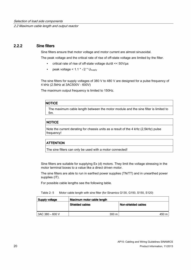
2.2.22.2.22.2.22.2.2 Sine filtersSine filtersSine filtersSine filters Sine filters ensure that motor voltage and motor current are almost sinusoidal.
The peak voltage and the critical rate of rise of off-state voltage are limited by the filter.
• critical rate of rise of off-state voltage du/dt << 50V/µs
• peak voltage < 1.1 * √2 * Usupply
The sine filters for supply voltages of 380 V to 480 V are designed for a pulse frequency of 4 kHz (2.5kHz at 3AC500V - 600V)
The maximum output frequency is limited to 150Hz.
NOTICENOTICENOTICENOTICE
The maximum cable length between the motor module and the sine filter is limited to 5m.
NOTICENOTICENOTICENOTICE
Note the current derating for chassis units as a result of the 4 kHz (2,5kHz) pulse frequency!
ATTENTIONATTENTIONATTENTIONATTENTION
The sine filters can only be used with a motor connected!
Sine filters are suitable for supplying Ex (d) motors. They limit the voltage stressing in the motor terminal boxes to a value like a direct driven motor.
The sine filters are able to run in earthed power supplies (TN/TT) and in unearthed power supplies (IT).
For possible cable lengths see the following table.
Table 2- 5 Motor cable length with sine filter (for Sinamics G130, G150, S150, S120)
Supply voltageSupply voltageSupply voltageSupply voltage Maximum motor cable lengthMaximum motor cable lengthMaximum motor cable lengthMaximum motor cable length Shielded cables Shielded cables Shielded cables Shielded cables
NonNonNonNon----shielded cablesshielded cablesshielded cablesshielded cables
3AC 380 – 600 V 300 m 450 m

Selection of load side components 2.2 Maximum cable length and output reactor
AP10: Cabling and Wiring Guidelines SINAMICS Product Information, 11/2013 21
Because of the increased pulse frequency (4kHz at 380-480V and 2.5kHz at 500-600V) the maximum output power is reduced. The following table shows the maximum output power with and without a sine filter.
Supply voltageSupply voltageSupply voltageSupply voltage Output powerOutput powerOutput powerOutput power Nominal Nominal Nominal Nominal output output output output currentcurrentcurrentcurrent
CurrentCurrentCurrentCurrent----DeratingDeratingDeratingDerating----FactorFactorFactorFactor
Output currentOutput currentOutput currentOutput current
without sine filterwithout sine filterwithout sine filterwithout sine filter without sine filterwithout sine filterwithout sine filterwithout sine filter with sine filterwith sine filterwith sine filterwith sine filter with sine filterwith sine filterwith sine filterwith sine filter
3AC 380V – 480V 110 kW 210 A 82% 172 A
3AC 380V – 480V 132 kW 260 A 83% 216 A
3AC 380V – 480V 160 kW 310 A 88% 273 A
3AC 380V – 480V 200 kW 380 A 87% 331 A
3AC 380V – 480V 250 kW 490 A 78% 382 A
3AC 500V – 600V 110 kW 175 A 87% 152 A
3AC 500V – 600V 132 kW 215 A 87% 187 A
Sizing of cable cross section
AP10: Cabling and Wiring Guidelines SINAMICS 22 Product Information, 11/2013
Sizing of cable cross sectionSizing of cable cross sectionSizing of cable cross sectionSizing of cable cross section 3333 3.13.13.13.1 ConductorsConductorsConductorsConductors
The selection of the correct cable cross-section takes place according to the data of the Sinamics components, the valid applying standards for the selection and calculation of cross sections and the manufacturer’s data of the selected cables.
But especially additional influencing factors, like ambient temperature, mechanical influences, method of laying as well as the permissible voltage drop have to be evaluated according the actual norms and rules.
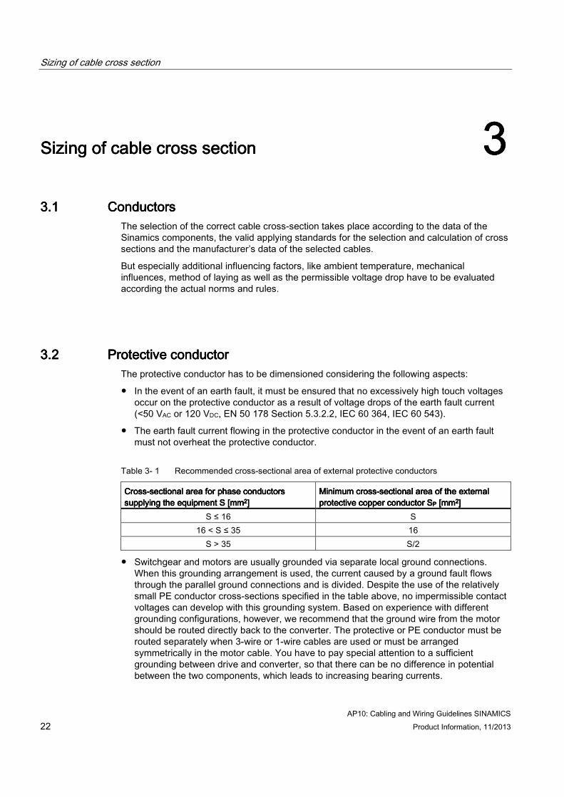
3.23.23.23.2 Protective conductorProtective conductorProtective conductorProtective conductor The protective conductor has to be dimensioned considering the following aspects:
● In the event of an earth fault, it must be ensured that no excessively high touch voltages occur on the protective conductor as a result of voltage drops of the earth fault current (<50 VAC or 120 VDC, EN 50 178 Section 5.3.2.2, IEC 60 364, IEC 60 543).
● The earth fault current flowing in the protective conductor in the event of an earth fault must not overheat the protective conductor.
Table 3- 1 Recommended cross-sectional area of external protective conductors
CrossCrossCrossCross----sectional area for phase conductors sectional area for phase conductors sectional area for phase conductors sectional area for phase conductors supplying the equipment S [mmsupplying the equipment S [mmsupplying the equipment S [mmsupplying the equipment S [mm2222]]]]
Minimum crossMinimum crossMinimum crossMinimum cross----sectional area of the external sectional area of the external sectional area of the external sectional area of the external protective copper conductor Sprotective copper conductor Sprotective copper conductor Sprotective copper conductor SPPPP [mm [mm [mm [mm2222]]]]
S ≤ 16 S 16 < S ≤ 35 16
S > 35 S/2
● Switchgear and motors are usually grounded via separate local ground connections. When this grounding arrangement is used, the current caused by a ground fault flows through the parallel ground connections and is divided. Despite the use of the relatively small PE conductor cross-sections specified in the table above, no impermissible contact voltages can develop with this grounding system. Based on experience with different grounding configurations, however, we recommend that the ground wire from the motor should be routed directly back to the converter. The protective or PE conductor must be routed separately when 3-wire or 1-wire cables are used or must be arranged symmetrically in the motor cable. You have to pay special attention to a sufficient grounding between drive and converter, so that there can be no difference in potential between the two components, which leads to increasing bearing currents.

Sizing of cable cross section 3.2 Protective conductor
AP10: Cabling and Wiring Guidelines SINAMICS Product Information, 11/2013 23
● Through their controllers, the converters limit the load current (motor and ground fault currents) to an rms value corresponding to the rated current. We therefore recommend the use of a PE conductor cross-section analogous to the phase conductor cross-section for grounding the converter cabinet.
Power cable selection
AP10: Cabling and Wiring Guidelines SINAMICS 24 Product Information, 11/2013
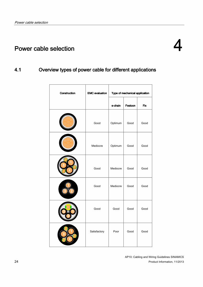
Power cable selectionPower cable selectionPower cable selectionPower cable selection 4444 4.14.14.14.1 Overview tOverview tOverview tOverview types of power cableypes of power cableypes of power cableypes of power cable for different for different for different for different applicationsapplicationsapplicationsapplications
Type of mechanical applicationType of mechanical applicationType of mechanical applicationType of mechanical application ConstructionConstructionConstructionConstruction EMC evaluationEMC evaluationEMC evaluationEMC evaluation
eeee----chainchainchainchain FestoonFestoonFestoonFestoon FixFixFixFix
Good Optimum Good Good
Bild single core unshielded
Mediocre Optimum Good Good
Good Mediocre Good Good
Good Mediocre Good Good
Good Good Good Good
Satisfactory Poor Good Good
1111
22223333
1111
3333 2222
1111
3333 5555 %%%%
1111 5555 %%%%
3333 5555 %%%%
1111 5555 %%%%
2222
3333
1111
2222
33333
333
5555 %%%%
1111
5555 %%%%
3333 5555
%%%%
1111 5555
%%%%
3333
5555
%%%%
1111
5555
%%%%
3333 5555
%%%%
1111 5555
%%%%
3333
5555
%%%%
1111
5555
%%%%
3333 5555
%%%%
1111 5555
%%%%
1111
2222
33333
333
5555 %%%%
1111
5555 %%%%
3333 5555
%%%%
1111 5555
%%%%
3333
5555
%%%%
1111
5555
%%%%
3333 5555
%%%%
1111 5555
%%%%
3333
5555
%%%%
1111
5555
%%%%
3333 5555
%%%%
1111 5555
%%%%

Power cable selection
AP10: Cabling and Wiring Guidelines SINAMICS Product Information, 11/2013 25
4.24.24.24.2 InsInsInsInsulation mulation mulation mulation material used for power cablesaterial used for power cablesaterial used for power cablesaterial used for power cables In view of minimizing the capacitance between the motor phase conductors and ground (see chapter High frequency disturbance (Page 7) ) it is advisable to choose cables with low capacitance materials like PP, PE, XLPE. Because the cable capacitance is directly proportional to the dielectrical constant of the insulation material of the cable.
Standard materials like PVC, or rubber are not suitable.
4.34.34.34.3 Installation guidelinesInstallation guidelinesInstallation guidelinesInstallation guidelines Typical wiring to the drive for the recommended power cable type
Figure 4-1 Earthing and screening for motor connection
Mediocre Mediocre Good Good
Poor Poor Good Mediocre
Poor Poor Good Mediocre
1111
3333 5555 %%%%
1111 5555 %%%%
3333 5555 %%%%
1111 5555 %%%%
2222
3333
Power cable selection 4.3 Installation guidelines
AP10: Cabling and Wiring Guidelines SINAMICS 26 Product Information, 11/2013
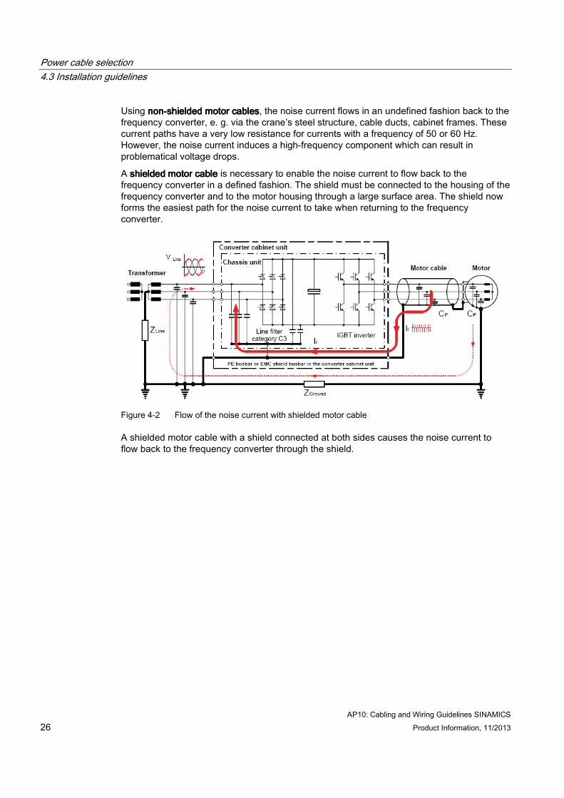
Using nonnonnonnon----shielded motor cablesshielded motor cablesshielded motor cablesshielded motor cables, the noise current flows in an undefined fashion back to the frequency converter, e. g. via the crane’s steel structure, cable ducts, cabinet frames. These current paths have a very low resistance for currents with a frequency of 50 or 60 Hz. However, the noise current induces a high-frequency component which can result in problematical voltage drops.
A shielded motor cable shielded motor cable shielded motor cable shielded motor cable is necessary to enable the noise current to flow back to the frequency converter in a defined fashion. The shield must be connected to the housing of the frequency converter and to the motor housing through a large surface area. The shield now forms the easiest path for the noise current to take when returning to the frequency converter.
Figure 4-2 Flow of the noise current with shielded motor cable
A shielded motor cable with a shield connected at both sides causes the noise current to flow back to the frequency converter through the shield.
Power cable selection 4.3 Installation guidelines
AP10: Cabling and Wiring Guidelines SINAMICS Product Information, 11/2013 27
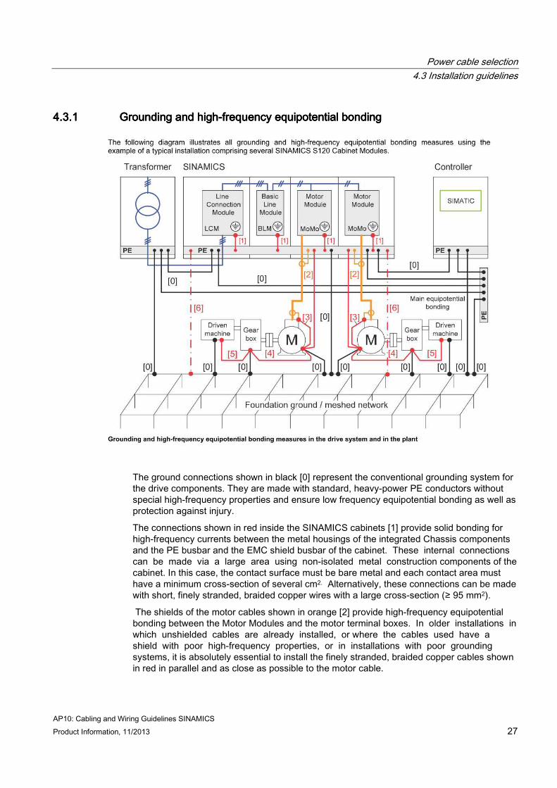
4.3.14.3.14.3.14.3.1 Grounding and highGrounding and highGrounding and highGrounding and high----frequency equipotential bondingfrequency equipotential bondingfrequency equipotential bondingfrequency equipotential bonding
The ground connections shown in black [0] represent the conventional grounding system for the drive components. They are made with standard, heavy-power PE conductors without special high-frequency properties and ensure low frequency equipotential bonding as well as protection against injury.
The connections shown in red inside the SINAMICS cabinets [1] provide solid bonding for high-frequency currents between the metal housings of the integrated Chassis components and the PE busbar and the EMC shield busbar of the cabinet. These internal connections can be made via a large area using non-isolated metal construction components of the cabinet. In this case, the contact surface must be bare metal and each contact area must have a minimum cross-section of several cm2. Alternatively, these connections can be made with short, finely stranded, braided copper wires with a large cross-section (≥ 95 mm2).
The shields of the motor cables shown in orange [2] provide high-frequency equipotential bonding between the Motor Modules and the motor terminal boxes. In older installations in which unshielded cables are already installed, or where the cables used have a shield with poor high-frequency properties, or in installations with poor grounding systems, it is absolutely essential to install the finely stranded, braided copper cables shown in red in parallel and as close as possible to the motor cable.
Power cable selection 4.3 Installation guidelines
AP10: Cabling and Wiring Guidelines SINAMICS 28 Product Information, 11/2013
The connections shown in red [3], [4] and [5] provide a conductive, high-frequency bond between the terminal box of the motor and the motor housing, and also between gearbox / driven machine and the motor housing. These connections can be omitted if the motor is constructed in such a way that a conductive, high-frequency bond is provided between the terminal box and the housing, and if motor, gearbox and driven machine are all in close proximity and all conductively bonded over a large area by means of a shared metallic structure, e.g. a metal machine bed.
The connections shown red dashed-and-dotted lines [6] provide a conductive, high-frequency bond between the cabinet frame and the foundation ground in the form of finely stranded, braided copper cables with large cross-section ( ≥ 95 mm2).
Note:
Grounding measures for machines are essentially a protective measure. However, in the case of drive systems, this also has an influence on the noise emission and noise immunity. A system can either be grounded in a star configuration or each component grounded separately. Preference should be given to the latter grounding system in the case of drive systems, i.e. all parts of the installation to be grounded are connected through their surface or in a mesh pattern.
Power cable selection 4.3 Installation guidelines
AP10: Cabling and Wiring Guidelines SINAMICS Product Information, 11/2013 29
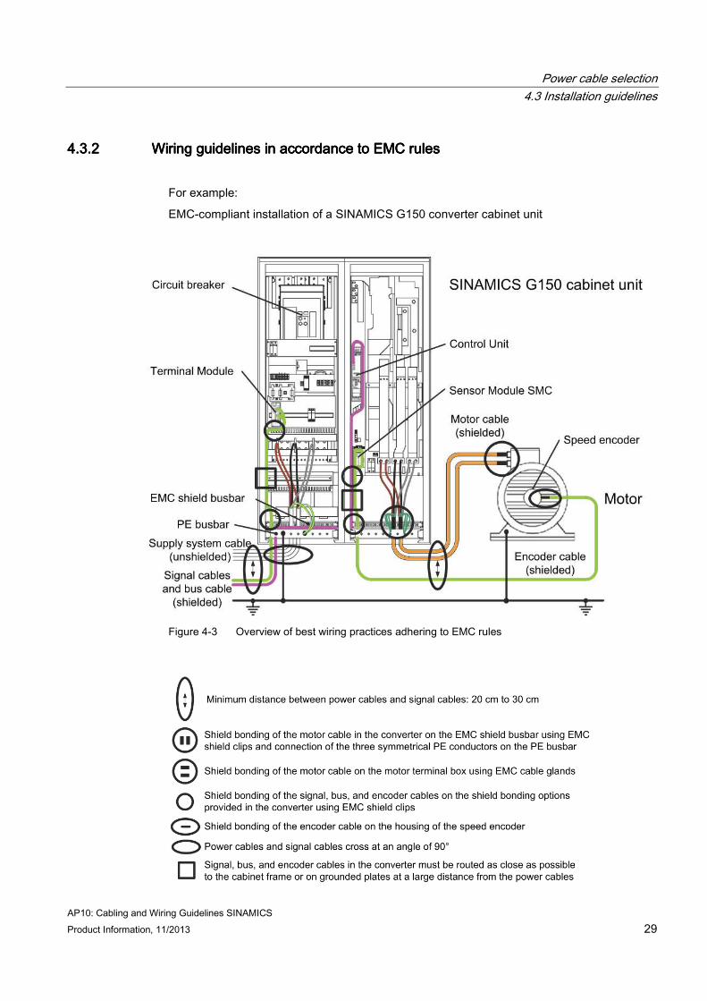
4.3.24.3.24.3.24.3.2 Wiring guidelines in accordance to EMC rulesWiring guidelines in accordance to EMC rulesWiring guidelines in accordance to EMC rulesWiring guidelines in accordance to EMC rules
For example:
EMC-compliant installation of a SINAMICS G150 converter cabinet unit
Figure 4-3 Overview of best wiring practices adhering to EMC rules

Power cable selection 4.3 Installation guidelines
AP10: Cabling and Wiring Guidelines SINAMICS 30 Product Information, 11/2013
Further rules to avoid troubles caused by EMC:
The shield between the motor and SINAMICS Motor Module must not be interrupted by the installation of components such as output reactors, sine filters, du/dt filters, fuses, contactors. The components must be mounted on a mounting panel which simultaneously serves as the shield connection for the incoming and outgoing motor cables. Grounded partitions may be necessary to shield the components.
All of the metal cabinet parts must be connected through the largest possible surface areas (not paint on paint). Serrated washers should be used to ensure a good metal-metal contact. The cabinet door must be connected to the cabinet through grounding straps which must be kept as short as possible.

Power cable selection 4.3 Installation guidelines
AP10: Cabling and Wiring Guidelines SINAMICS Product Information, 11/2013 31
Contactors, relays, solenoid valves, surge arrestors, electromechanical operating hours counters, etc. in the cabinet must be provided with surge suppressor devices, for example, RC elements, diodes, varistors. These surge suppressor devices must be connected directly at the coil.
Non-shielded cables associated with the same circuit (outgoing and incoming conductor) must be twisted, or the surface between the outgoing and incoming conductors kept as small as possible in order to prevent unnecessary coupling effects.
Connect the reserve cables/conductors to ground at both ends to achieve an additional shielding effect.
In general, it is possible to reduce the noise being coupled-in by routing cables close to grounded cabinet panels. Therefore, wiring should be routed as close as possible to the cabinet housing and the mounting panels and not freely through the cabinet. The same applies for reserve cables/conductors.
Prevent noise from being coupled-in through the supply. SINAMICS Motor Modules and PLC / control electronics should be connected-up to different supply networks. If there is only one common network, the PLC / control electronics have to be de-coupled from the supply using an isolating transformer.
Power cable selection 4.3 Installation guidelines
AP10: Cabling and Wiring Guidelines SINAMICS 32 Product Information, 11/2013
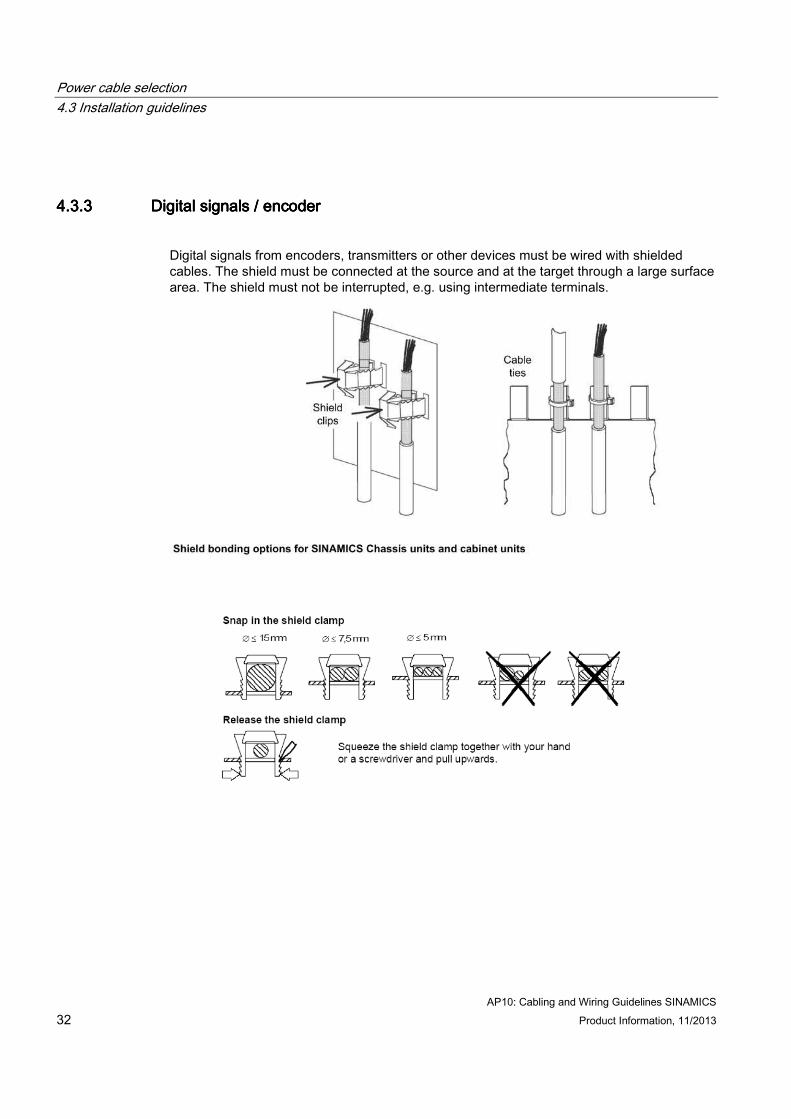
4.3.34.3.34.3.34.3.3 Digital signals / encoderDigital signals / encoderDigital signals / encoderDigital signals / encoder
Digital signals from encoders, transmitters or other devices must be wired with shielded cables. The shield must be connected at the source and at the target through a large surface area. The shield must not be interrupted, e.g. using intermediate terminals.
Power cable selection 4.3 Installation guidelines
AP10: Cabling and Wiring Guidelines SINAMICS Product Information, 11/2013 33
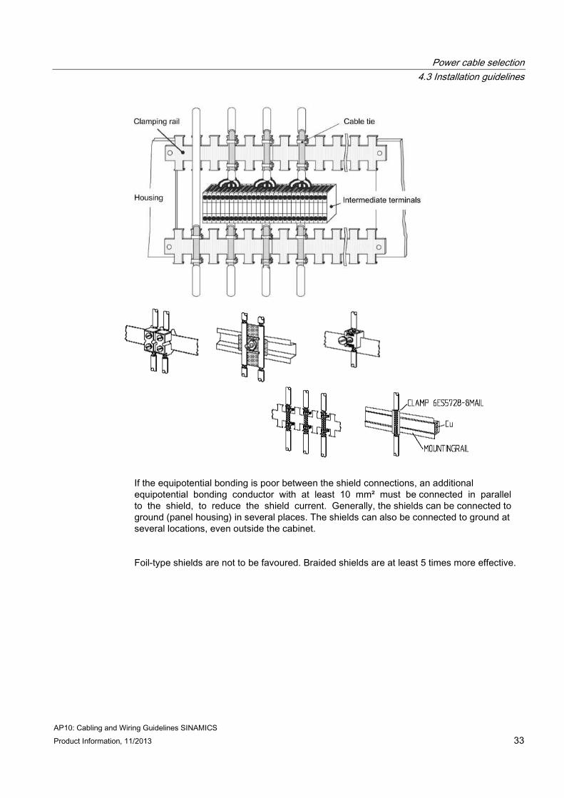
If the equipotential bonding is poor between the shield connections, an additional equipotential bonding conductor with at least 10 mm² must be connected in parallel to the shield, to reduce the shield current. Generally, the shields can be connected to ground (panel housing) in several places. The shields can also be connected to ground at several locations, even outside the cabinet.
Foil-type shields are not to be favoured. Braided shields are at least 5 times more effective.
Power cable selection 4.3 Installation guidelines
AP10: Cabling and Wiring Guidelines SINAMICS 34 Product Information, 11/2013
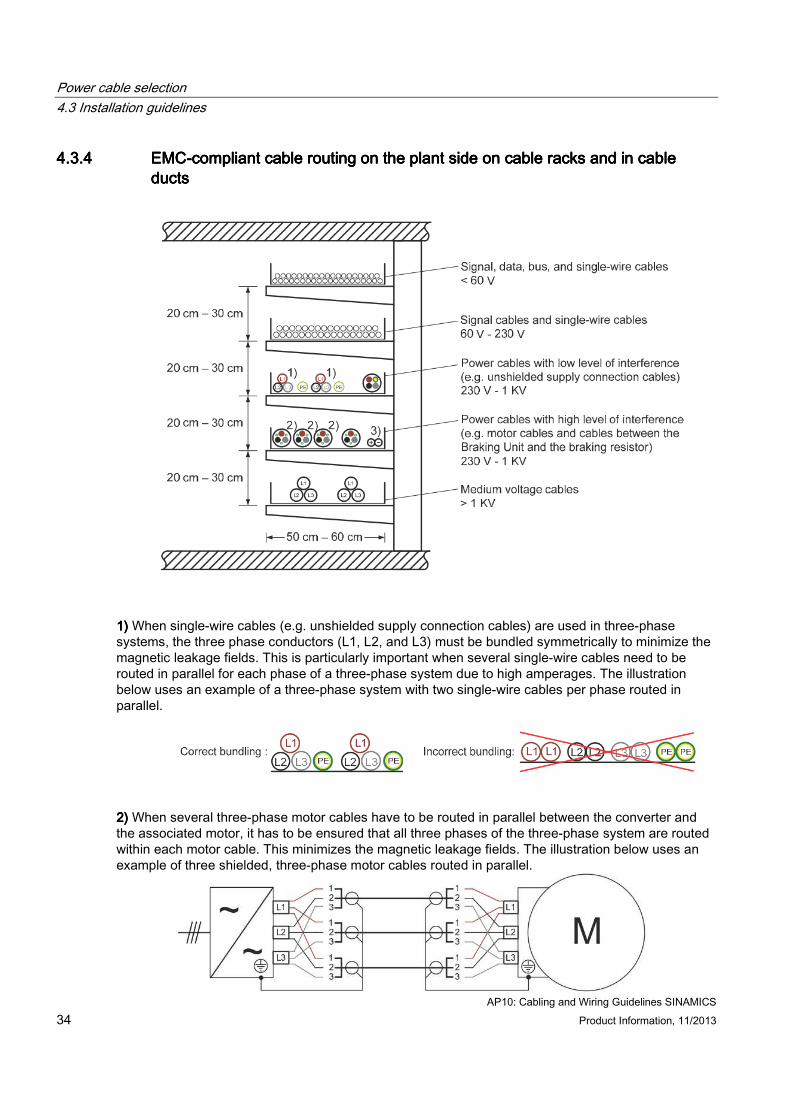
4.3.44.3.44.3.44.3.4 EMCEMCEMCEMC----compliant cable routing on the plant side on cable racks and in cable compliant cable routing on the plant side on cable racks and in cable compliant cable routing on the plant side on cable racks and in cable compliant cable routing on the plant side on cable racks and in cable ducts ducts ducts ducts
1)1)1)1) When single-wire cables (e.g. unshielded supply connection cables) are used in three-phase systems, the three phase conductors (L1, L2, and L3) must be bundled symmetrically to minimize the magnetic leakage fields. This is particularly important when several single-wire cables need to be routed in parallel for each phase of a three-phase system due to high amperages. The illustration below uses an example of a three-phase system with two single-wire cables per phase routed in parallel.
2)2)2)2) When several three-phase motor cables have to be routed in parallel between the converter and the associated motor, it has to be ensured that all three phases of the three-phase system are routed within each motor cable. This minimizes the magnetic leakage fields. The illustration below uses an example of three shielded, three-phase motor cables routed in parallel.
Power cable selection 4.3 Installation guidelines
AP10: Cabling and Wiring Guidelines SINAMICS Product Information, 11/2013 35
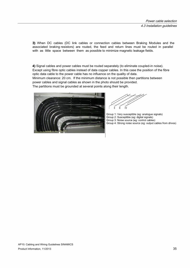
3)3)3)3) When DC cables (DC link cables or connection cables between Braking Modules and the associated braking resistors) are routed, the feed and return lines must be routed in parallel with as little space between them as possible to minimize magnetic leakage fields.
4)4)4)4) Signal cables and power cables must be routed separately (to eliminate coupled-in noise). Except using fibre optic cables instead of data copper cables. In this case the position of the fibre optic data cable to the power cable has no influence on the quality of data. Minimum clearance: 20 cm. If the minimum distance is not possible then partitions between power cables and signal cables as shown in the photo should be provided. The partitions must be grounded at several points along their length.
Power cable selection 4.3 Installation guidelines
AP10: Cabling and Wiring Guidelines SINAMICS 36 Product Information, 11/2013
4.3.54.3.54.3.54.3.5 Wiring requirements as per IEC 60204Wiring requirements as per IEC 60204Wiring requirements as per IEC 60204Wiring requirements as per IEC 60204----32323232
NoteNoteNoteNote
All entries of "chapter" in the following refer to the respective chapters in IEC 60204-32.
● All connections must be securely fastened to prevent accidental loosening (chapter 13.1.1).
● One protective conductor must be connected to one terminal connecting point unless the terminal is designed for two or more conductors (chapter 13.1.1).
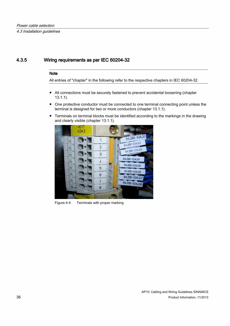
● Terminals on terminal blocks must be identified according to the markings in the drawing and clearly visible (chapter 13.1.1).
Figure 4-4 Terminals with proper marking
Power cable selection 4.3 Installation guidelines
AP10: Cabling and Wiring Guidelines SINAMICS Product Information, 11/2013 37
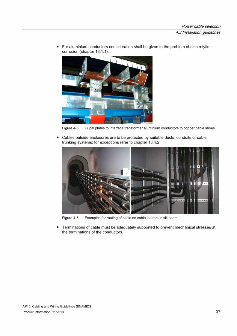
● For aluminium conductors consideration shall be given to the problem of electrolytic corrosion (chapter 13.1.1).
Figure 4-5 Cupal plates to interface transformer aluminium conductors to copper cable shoes
● Cables outside enclosures are to be protected by suitable ducts, conduits or cable trunking systems; for exceptions refer to chapter 13.4.2.
Figure 4-6 Examples for routing of cable on cable ladders in sill beam
● Terminations of cable must be adequately supported to prevent mechanical stresses at the terminations of the conductors.
Power cable selection 4.3 Installation guidelines
AP10: Cabling and Wiring Guidelines SINAMICS 38 Product Information, 11/2013
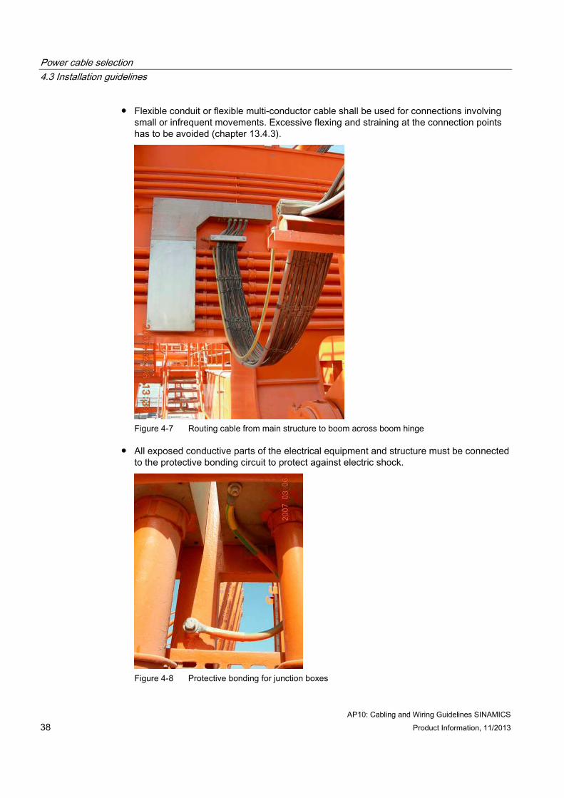
● Flexible conduit or flexible multi-conductor cable shall be used for connections involving small or infrequent movements. Excessive flexing and straining at the connection points has to be avoided (chapter 13.4.3).
Figure 4-7 Routing cable from main structure to boom across boom hinge
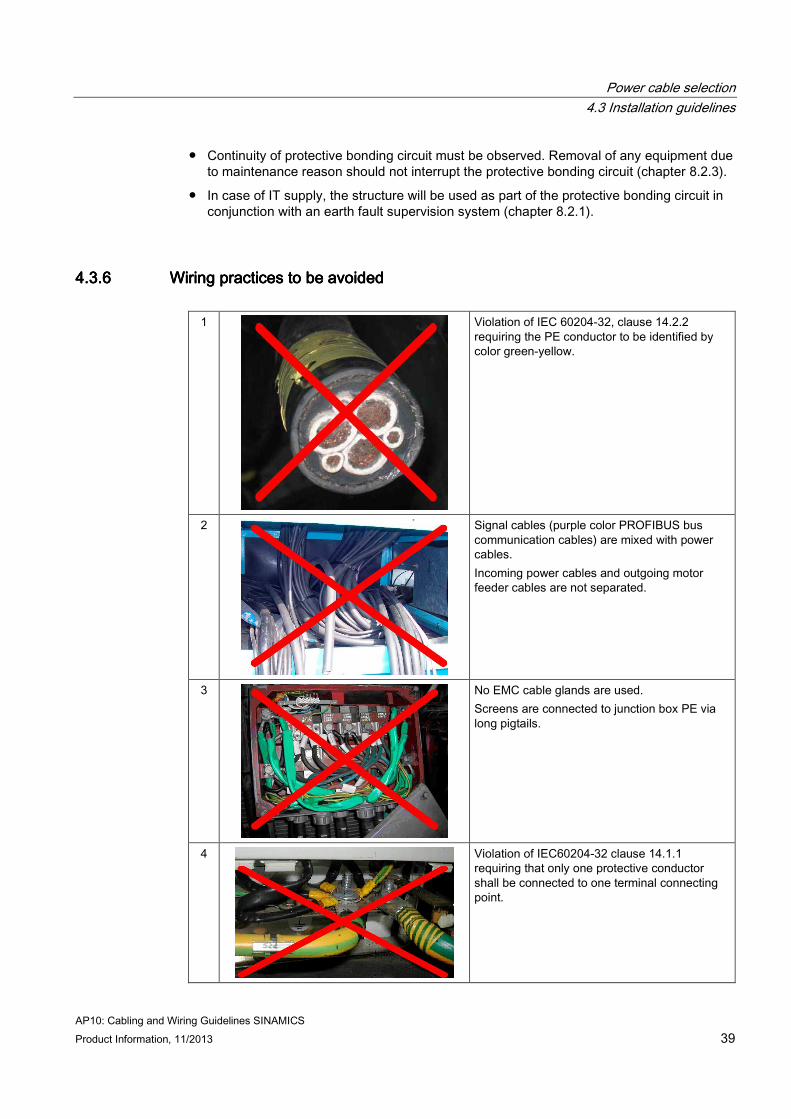
● All exposed conductive parts of the electrical equipment and structure must be connected to the protective bonding circuit to protect against electric shock.
Figure 4-8 Protective bonding for junction boxes
Power cable selection 4.3 Installation guidelines
AP10: Cabling and Wiring Guidelines SINAMICS Product Information, 11/2013 39
● Continuity of protective bonding circuit must be observed. Removal of any equipment due to maintenance reason should not interrupt the protective bonding circuit (chapter 8.2.3).
● In case of IT supply, the structure will be used as part of the protective bonding circuit in conjunction with an earth fault supervision system (chapter 8.2.1).
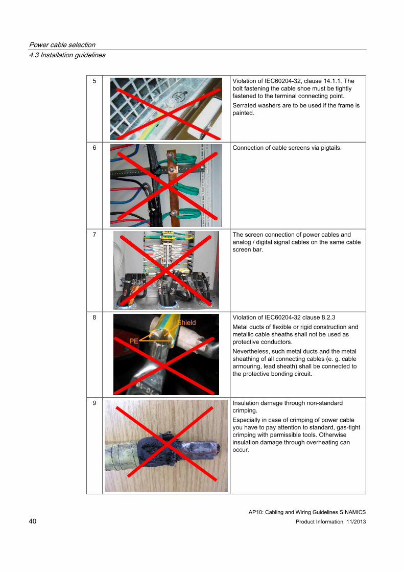
4.3.64.3.64.3.64.3.6 Wiring practices to be avoidedWiring practices to be avoidedWiring practices to be avoidedWiring practices to be avoided
1
Violation of IEC 60204-32, clause 14.2.2 requiring the PE conductor to be identified by color green-yellow.
2
Signal cables (purple color PROFIBUS bus communication cables) are mixed with power cables. Incoming power cables and outgoing motor feeder cables are not separated.
3
No EMC cable glands are used. Screens are connected to junction box PE via long pigtails.
4
Violation of IEC60204-32 clause 14.1.1 requiring that only one protective conductor shall be connected to one terminal connecting point.
Power cable selection 4.3 Installation guidelines
AP10: Cabling and Wiring Guidelines SINAMICS 40 Product Information, 11/2013
5
Violation of IEC60204-32, clause 14.1.1. The bolt fastening the cable shoe must be tightly fastened to the terminal connecting point. Serrated washers are to be used if the frame is painted.
6
Connection of cable screens via pigtails.
7
The screen connection of power cables and analog / digital signal cables on the same cable screen bar.
8
Violation of IEC60204-32 clause 8.2.3 Metal ducts of flexible or rigid construction and metallic cable sheaths shall not be used as protective conductors. Nevertheless, such metal ducts and the metal sheathing of all connecting cables (e. g. cable armouring, lead sheath) shall be connected to the protective bonding circuit.
9
Insulation damage through non-standard crimping. Especially in case of crimping of power cable you have to pay attention to standard, gas-tight crimping with permissible tools. Otherwise insulation damage through overheating can occur.
Power cable selection 4.3 Installation guidelines
AP10: Cabling and Wiring Guidelines SINAMICS Product Information, 11/2013 41
4.3.74.3.74.3.74.3.7 Best practices for screened power cable terminationBest practices for screened power cable terminationBest practices for screened power cable terminationBest practices for screened power cable termination The following sections show best practices for terminating screened power cable at the output of drive, intermediate junction box and motor junction box.
4.3.7.14.3.7.14.3.7.14.3.7.1 Termination in drive unitTermination in drive unitTermination in drive unitTermination in drive unit
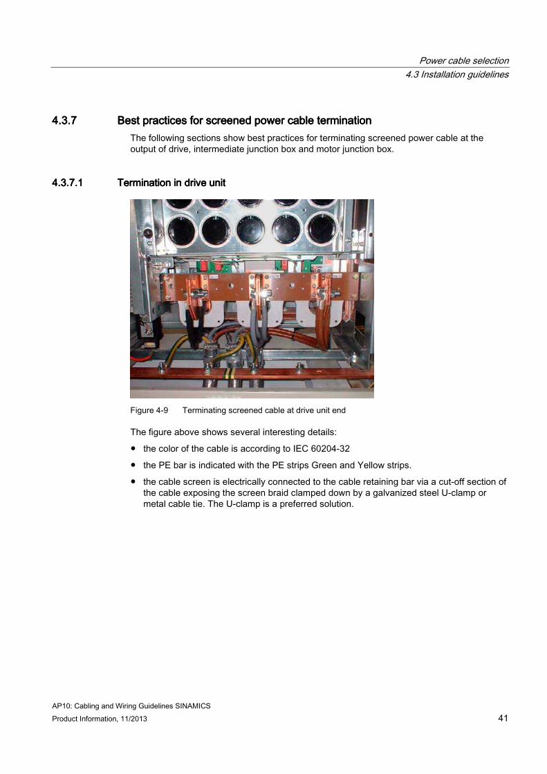
Figure 4-9 Terminating screened cable at drive unit end
The figure above shows several interesting details:
● the color of the cable is according to IEC 60204-32
● the PE bar is indicated with the PE strips Green and Yellow strips.
● the cable screen is electrically connected to the cable retaining bar via a cut-off section of the cable exposing the screen braid clamped down by a galvanized steel U-clamp or metal cable tie. The U-clamp is a preferred solution.
Power cable selection 4.3 Installation guidelines
AP10: Cabling and Wiring Guidelines SINAMICS 42 Product Information, 11/2013
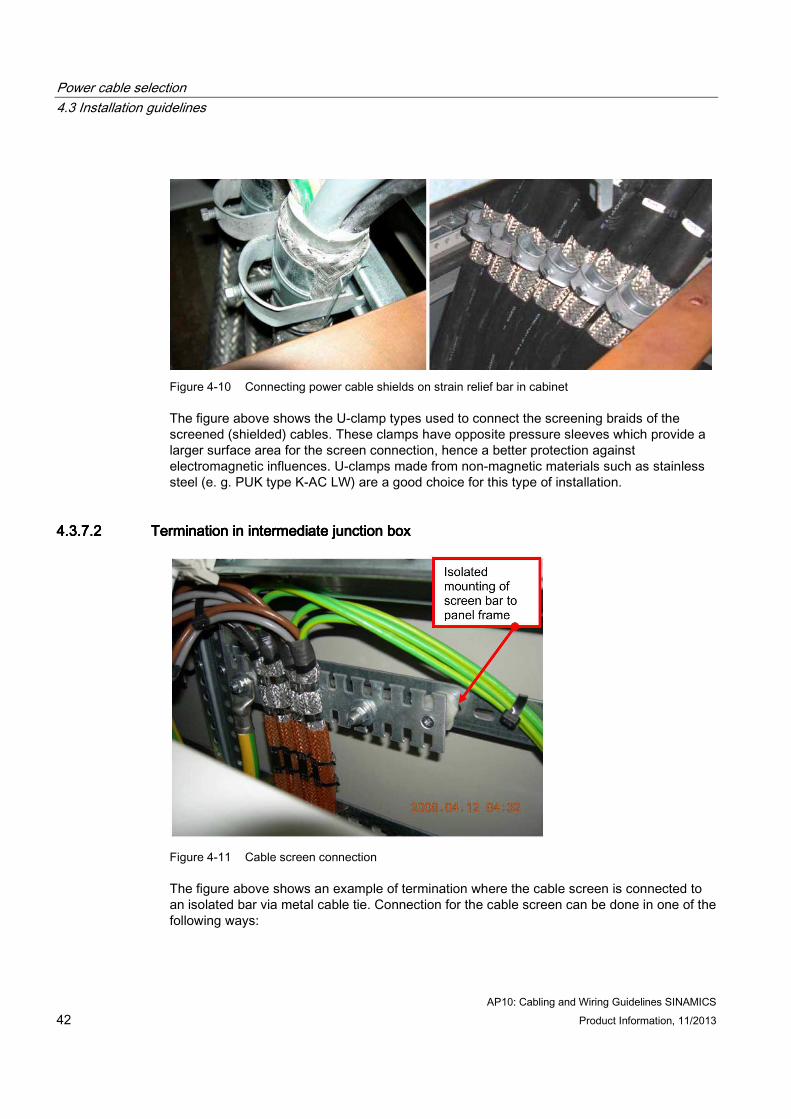
Figure 4-10 Connecting power cable shields on strain relief bar in cabinet
The figure above shows the U-clamp types used to connect the screening braids of the screened (shielded) cables. These clamps have opposite pressure sleeves which provide a larger surface area for the screen connection, hence a better protection against electromagnetic influences. U-clamps made from non-magnetic materials such as stainless steel (e. g. PUK type K-AC LW) are a good choice for this type of installation.
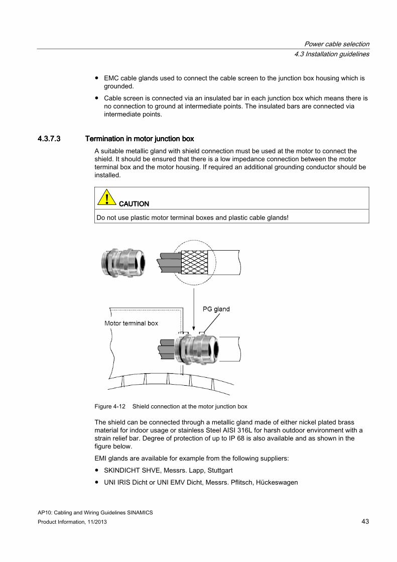
4.3.7.24.3.7.24.3.7.24.3.7.2 Termination in intermediate junction boxTermination in intermediate junction boxTermination in intermediate junction boxTermination in intermediate junction box
Figure 4-11 Cable screen connection
The figure above shows an example of termination where the cable screen is connected to an isolated bar via metal cable tie. Connection for the cable screen can be done in one of the following ways:
Power cable selection 4.3 Installation guidelines
AP10: Cabling and Wiring Guidelines SINAMICS Product Information, 11/2013 43
● EMC cable glands used to connect the cable screen to the junction box housing which is grounded.
● Cable screen is connected via an insulated bar in each junction box which means there is no connection to ground at intermediate points. The insulated bars are connected via intermediate points.
4.3.7.34.3.7.34.3.7.34.3.7.3 Termination in motor junction boxTermination in motor junction boxTermination in motor junction boxTermination in motor junction box A suitable metallic gland with shield connection must be used at the motor to connect the shield. It should be ensured that there is a low impedance connection between the motor terminal box and the motor housing. If required an additional grounding conductor should be installed.
! CAUTIONCAUTIONCAUTIONCAUTION
Do not use plastic motor terminal boxes and plastic cable glands!
Figure 4-12 Shield connection at the motor junction box
The shield can be connected through a metallic gland made of either nickel plated brass material for indoor usage or stainless Steel AISI 316L for harsh outdoor environment with a strain relief bar. Degree of protection of up to IP 68 is also available and as shown in the figure below.
EMI glands are available for example from the following suppliers:
● SKINDICHT SHVE, Messrs. Lapp, Stuttgart
● UNI IRIS Dicht or UNI EMV Dicht, Messrs. Pflitsch, Hückeswagen
Power cable selection 4.3 Installation guidelines
AP10: Cabling and Wiring Guidelines SINAMICS 44 Product Information, 11/2013
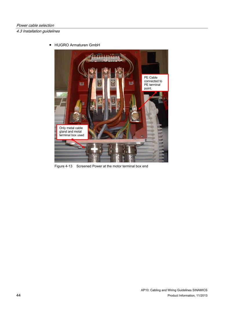
● HUGRO Armaturen GmbH
Figure 4-13 Screened Power at the motor terminal box end
Power cable selection 4.3 Installation guidelines
AP10: Cabling and Wiring Guidelines SINAMICS Product Information, 11/2013 45
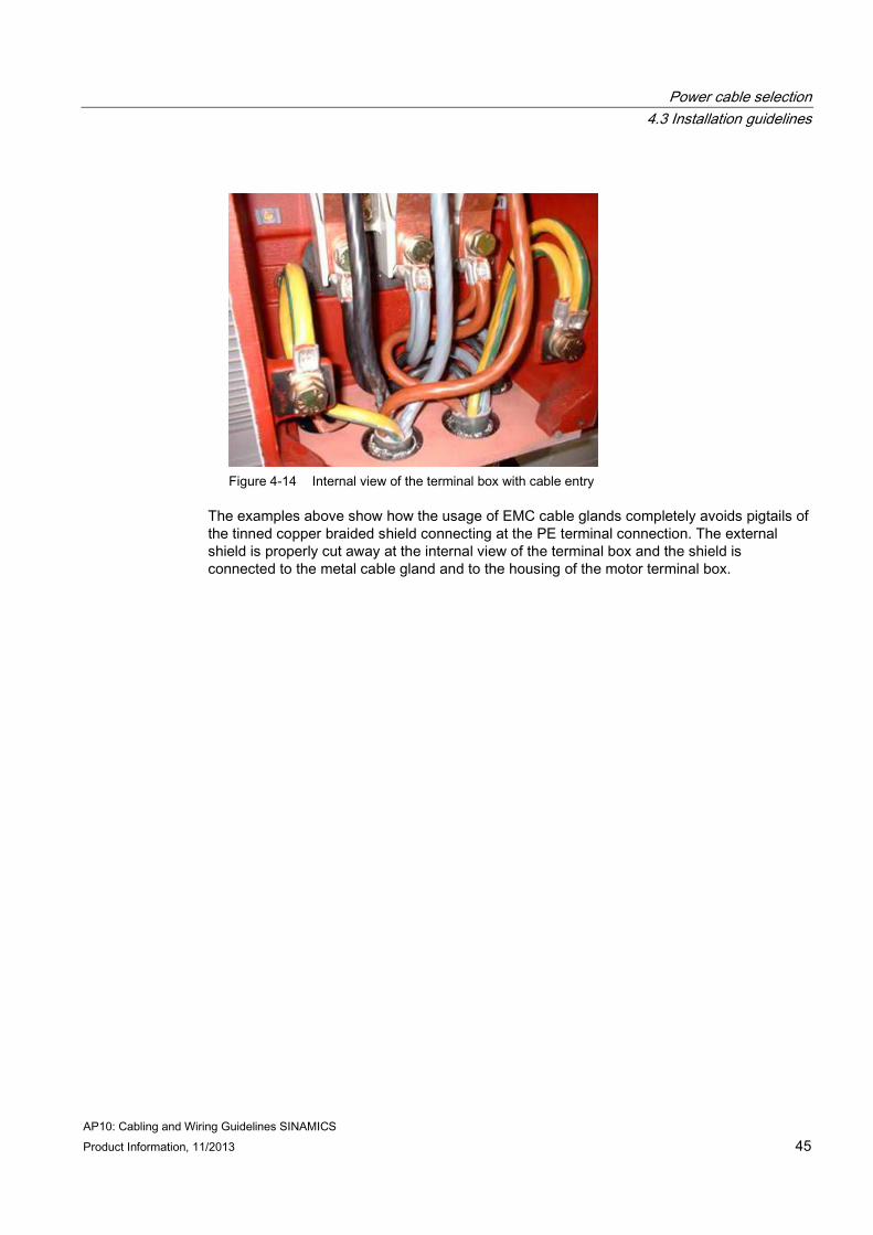
Figure 4-14 Internal view of the terminal box with cable entry
The examples above show how the usage of EMC cable glands completely avoids pigtails of the tinned copper braided shield connecting at the PE terminal connection. The external shield is properly cut away at the internal view of the terminal box and the shield is connected to the metal cable gland and to the housing of the motor terminal box.

AP10: Cabling and Wiring Guidelines SINAMICS Product Information, 11/2013 47
Installation of control cablesInstallation of control cablesInstallation of control cablesInstallation of control cables 5555 5.15.15.15.1 Installation of PROFIBUS cablesInstallation of PROFIBUS cablesInstallation of PROFIBUS cablesInstallation of PROFIBUS cables
When you are laying the bus cable:
● Don't twist it!
● Don't stretch it!
● Don't squash it!
In addition to this, you must take into account any influences on electromagnetic compatibility (EMC).
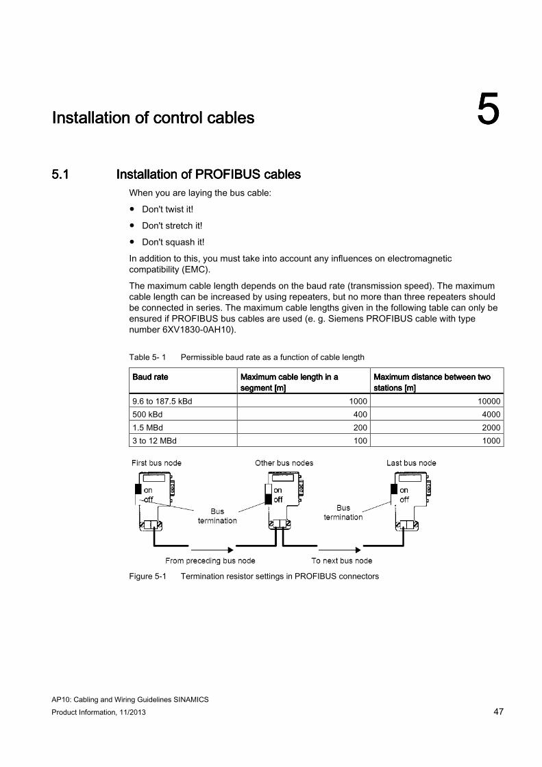
The maximum cable length depends on the baud rate (transmission speed). The maximum cable length can be increased by using repeaters, but no more than three repeaters should be connected in series. The maximum cable lengths given in the following table can only be ensured if PROFIBUS bus cables are used (e. g. Siemens PROFIBUS cable with type number 6XV1830-0AH10).
Table 5- 1 Permissible baud rate as a function of cable length
Baud rateBaud rateBaud rateBaud rate Maximum cable length in a Maximum cable length in a Maximum cable length in a Maximum cable length in a segment [m]segment [m]segment [m]segment [m]
Maximum distance between two Maximum distance between two Maximum distance between two Maximum distance between two stations [m]stations [m]stations [m]stations [m]
9.6 to 187.5 kBd 1000 10000 500 kBd 400 4000 1.5 MBd 200 2000 3 to 12 MBd 100 1000
Figure 5-1 Termination resistor settings in PROFIBUS connectors
Installation of control cables 5.1 Installation of PROFIBUS cables
AP10: Cabling and Wiring Guidelines SINAMICS 48 Product Information, 11/2013
Shielding of the bus cable / EMC measuresShielding of the bus cable / EMC measuresShielding of the bus cable / EMC measuresShielding of the bus cable / EMC measures In order to ensure interference-free operation of the PROFIBUS-DP especially in case of data transmission with RS485 the following measures are imperative:
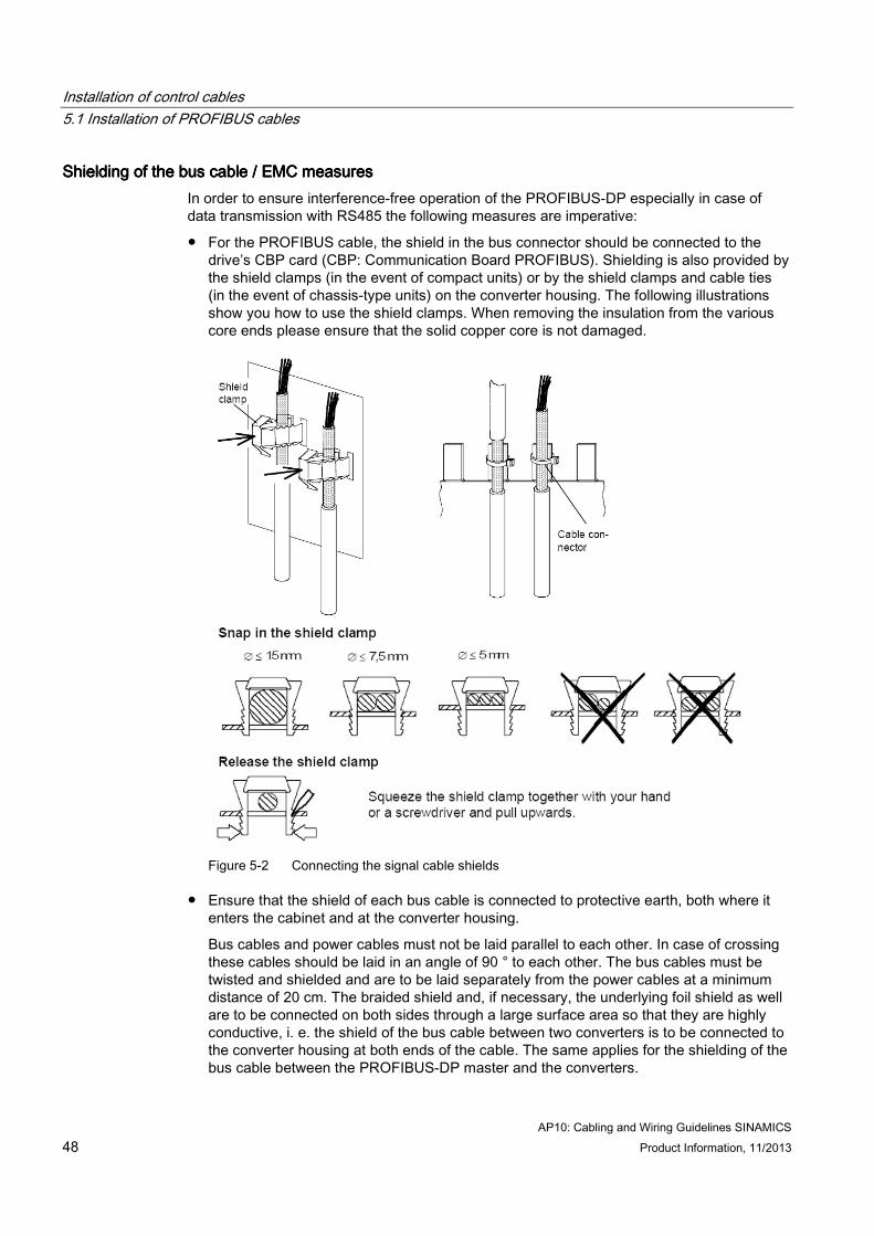
● For the PROFIBUS cable, the shield in the bus connector should be connected to the drive’s CBP card (CBP: Communication Board PROFIBUS). Shielding is also provided by the shield clamps (in the event of compact units) or by the shield clamps and cable ties (in the event of chassis-type units) on the converter housing. The following illustrations show you how to use the shield clamps. When removing the insulation from the various core ends please ensure that the solid copper core is not damaged.
Figure 5-2 Connecting the signal cable shields
● Ensure that the shield of each bus cable is connected to protective earth, both where it enters the cabinet and at the converter housing.
Bus cables and power cables must not be laid parallel to each other. In case of crossing these cables should be laid in an angle of 90 ° to each other. The bus cables must be twisted and shielded and are to be laid separately from the power cables at a minimum distance of 20 cm. The braided shield and, if necessary, the underlying foil shield as well are to be connected on both sides through a large surface area so that they are highly conductive, i. e. the shield of the bus cable between two converters is to be connected to the converter housing at both ends of the cable. The same applies for the shielding of the bus cable between the PROFIBUS-DP master and the converters.
Installation of control cables 5.2 Installation of encoder cables
AP10: Cabling and Wiring Guidelines SINAMICS Product Information, 11/2013 49
MUST BE REPLACED BY A SINAMICS EXAMPLE Figure 5-3 Installation with separate cable ducts
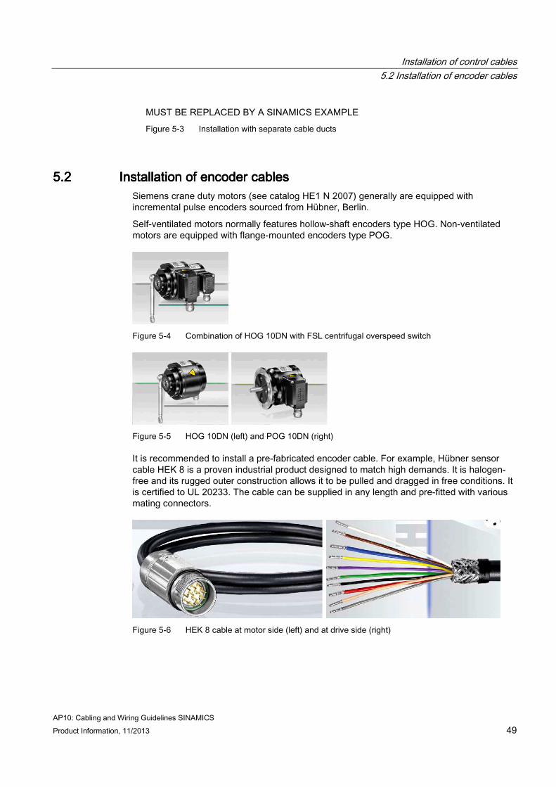
5.25.25.25.2 Installation of encoder cablesInstallation of encoder cablesInstallation of encoder cablesInstallation of encoder cables Siemens crane duty motors (see catalog HE1 N 2007) generally are equipped with incremental pulse encoders sourced from Hübner, Berlin.
Self-ventilated motors normally features hollow-shaft encoders type HOG. Non-ventilated motors are equipped with flange-mounted encoders type POG.
Figure 5-4 Combination of HOG 10DN with FSL centrifugal overspeed switch
Figure 5-5 HOG 10DN (left) and POG 10DN (right)
It is recommended to install a pre-fabricated encoder cable. For example, Hübner sensor cable HEK 8 is a proven industrial product designed to match high demands. It is halogen-free and its rugged outer construction allows it to be pulled and dragged in free conditions. It is certified to UL 20233. The cable can be supplied in any length and pre-fitted with various mating connectors.
Figure 5-6 HEK 8 cable at motor side (left) and at drive side (right)
Installation of control cables 5.2 Installation of encoder cables
AP10: Cabling and Wiring Guidelines SINAMICS 50 Product Information, 11/2013
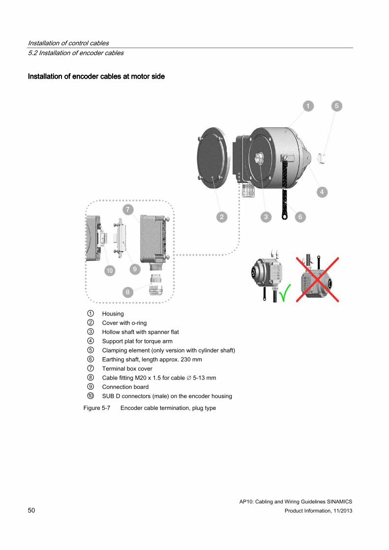
Installation of encoder cables at motor sideInstallation of encoder cables at motor sideInstallation of encoder cables at motor sideInstallation of encoder cables at motor side
① Housing ② Cover with o-ring ③ Hollow shaft with spanner flat ④ Support plat for torque arm ⑤ Clamping element (only version with cylinder shaft) ⑥ Earthing shaft, length approx. 230 mm ⑦ Terminal box cover ⑧ Cable fitting M20 x 1.5 for cable ∅ 5-13 mm ⑨ Connection board ⑩ SUB D connectors (male) on the encoder housing
Figure 5-7 Encoder cable termination, plug type

Installation of control cables 5.2 Installation of encoder cables
AP10: Cabling and Wiring Guidelines SINAMICS Product Information, 11/2013 51
Figure 5-8 Encoder cable termination, terminal type
Figure 5-9 Encoder cable terminal

Installation of control cables 5.2 Installation of encoder cables
AP10: Cabling and Wiring Guidelines SINAMICS 52 Product Information, 11/2013
InstallatInstallatInstallatInstallation of encoder cables at drive sideion of encoder cables at drive sideion of encoder cables at drive sideion of encoder cables at drive side The encoder cable will be installed in the same manner as the PROFIBUS cable with all the precautions mentioned. After the shield is properly connected as according to chapter Installation of PROFIBUS cables (Page 47), the cables can be connected to the detachable terminal strips of either the encoder interface (e.g. SMC30, SMC20) of the drives.
Figure 5-10 Encoder cable signals
AP10: Cabling and Wiring Guidelines SINAMICS Product Information, 11/2013 53
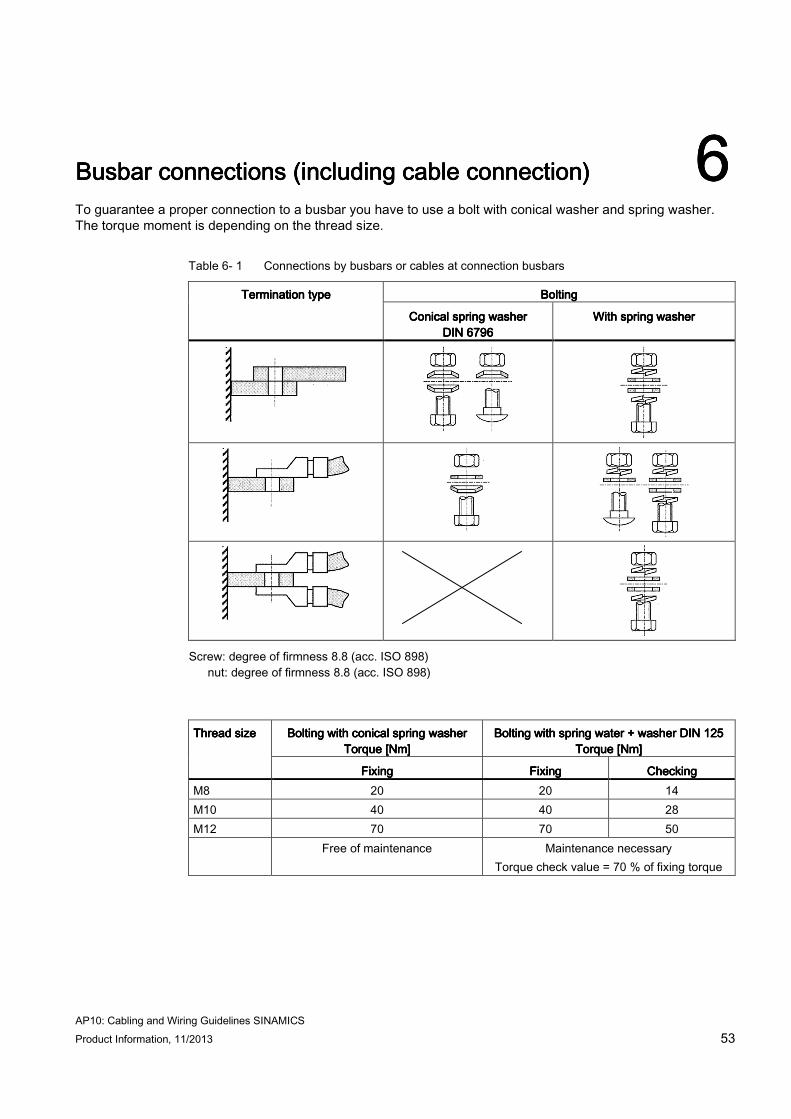
Busbar connections (including cable connection)Busbar connections (including cable connection)Busbar connections (including cable connection)Busbar connections (including cable connection) 6666 To guarantee a proper connection to a busbar you have to use a bolt with conical washer and spring washer. The torque moment is depending on the thread size.
Table 6- 1 Connections by busbars or cables at connection busbars
BoltingBoltingBoltingBolting Termination typeTermination typeTermination typeTermination type
Conical spring washer Conical spring washer Conical spring washer Conical spring washer DINDINDINDIN 6796679667966796
With spring washerWith spring washerWith spring washerWith spring washer
Screw: degree of firmness 8.8 (acc. ISO 898) nut: degree of firmness 8.8 (acc. ISO 898)
Bolting with conical spring washerBolting with conical spring washerBolting with conical spring washerBolting with conical spring washer
Torque [Nm]Torque [Nm]Torque [Nm]Torque [Nm] Bolting with spring water + washer DINBolting with spring water + washer DINBolting with spring water + washer DINBolting with spring water + washer DIN 125125125125
Torque [Nm]Torque [Nm]Torque [Nm]Torque [Nm] Thread sizeThread sizeThread sizeThread size
FixingFixingFixingFixing FixingFixingFixingFixing CheckingCheckingCheckingChecking M8 20 20 14 M10 40 40 28 M12 70 70 50 Free of maintenance Maintenance necessary
Torque check value = 70 % of fixing torque

Appendix
AP10: Cabling and Wiring Guidelines SINAMICS Product Information, 11/2013
54
Installation of Installation of Installation of Installation of eeee----chainchainchainchain®®®® and and and and chainflexchainflexchainflexchainflex®®®® cables cables cables cables 7777
Appendix
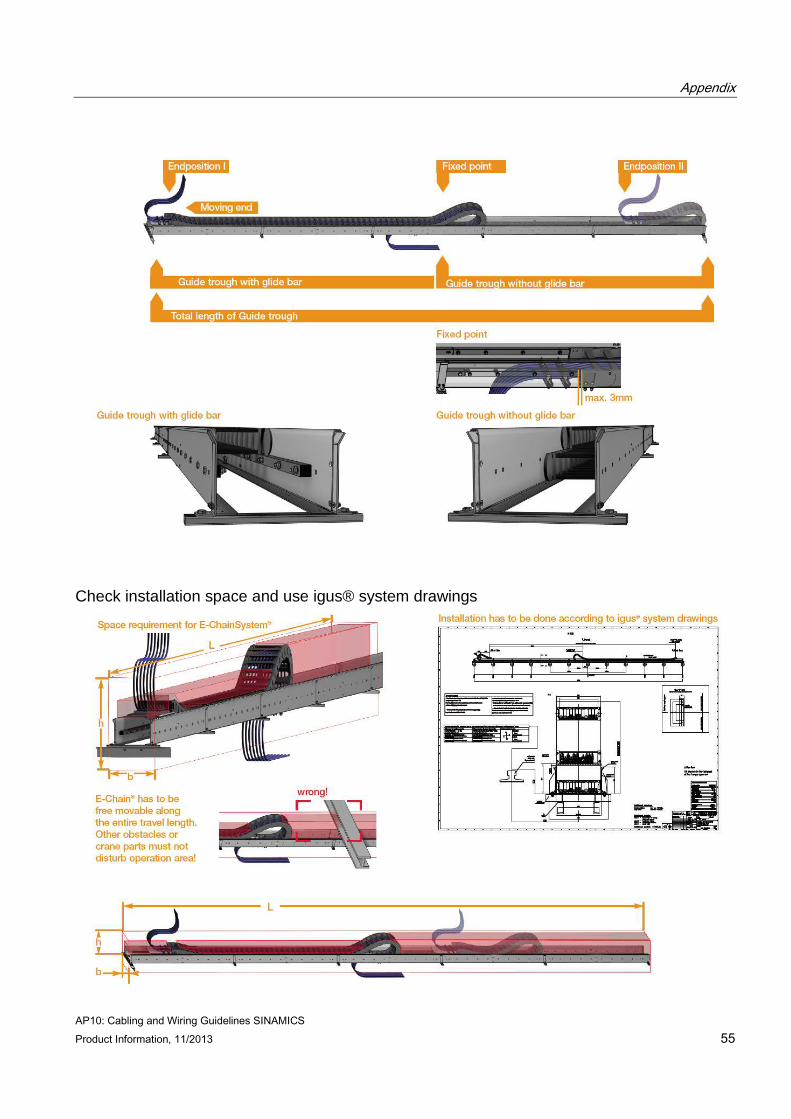
AP10: Cabling and Wiring Guidelines SINAMICS Product Information, 11/2013 55
Check installation space and use igus® system drawings

Appendix
AP10: Cabling and Wiring Guidelines SINAMICS Product Information, 11/2013
56
Support Structure for guiding trough
Guide trough installation
Appendix
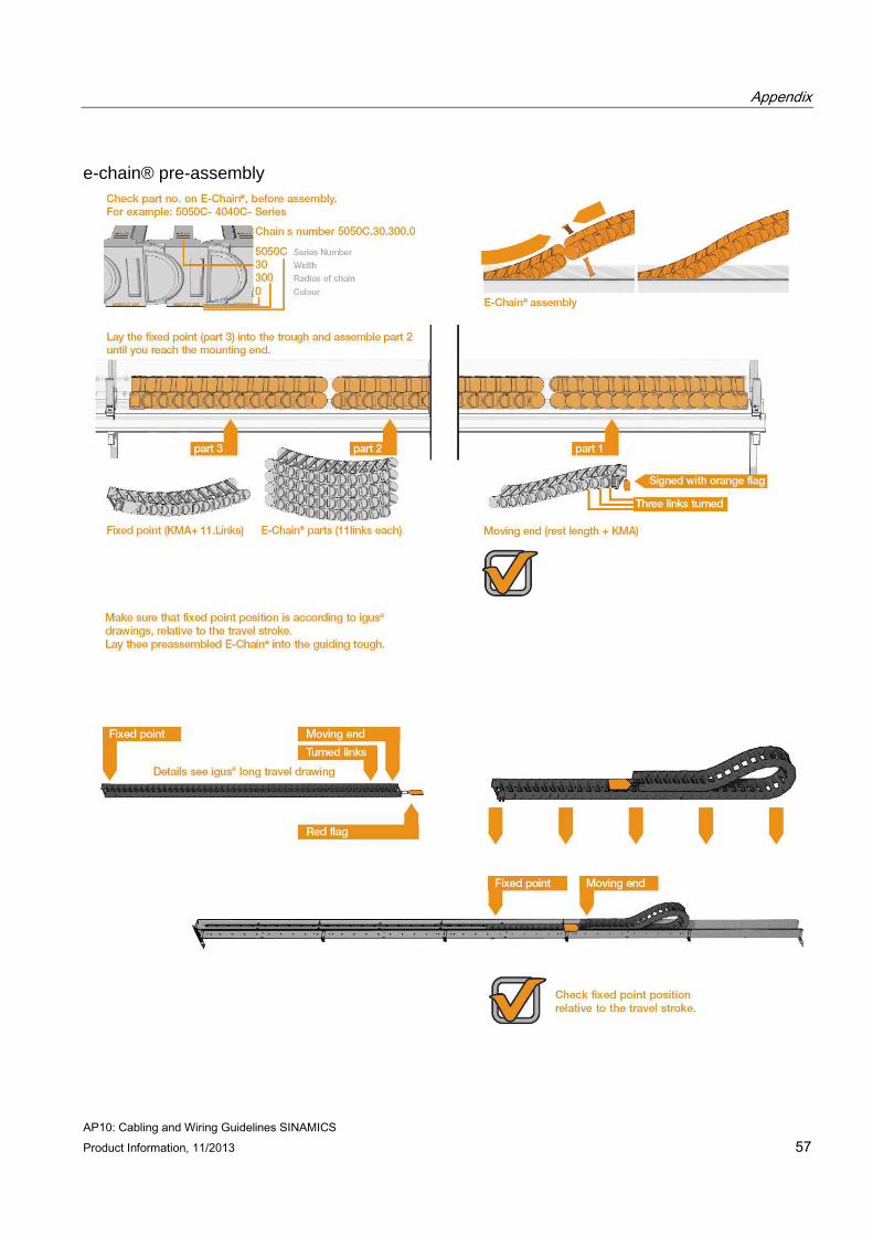
AP10: Cabling and Wiring Guidelines SINAMICS Product Information, 11/2013 57
e-chain® pre-assembly
Appendix
AP10: Cabling and Wiring Guidelines SINAMICS Product Information, 11/2013
58
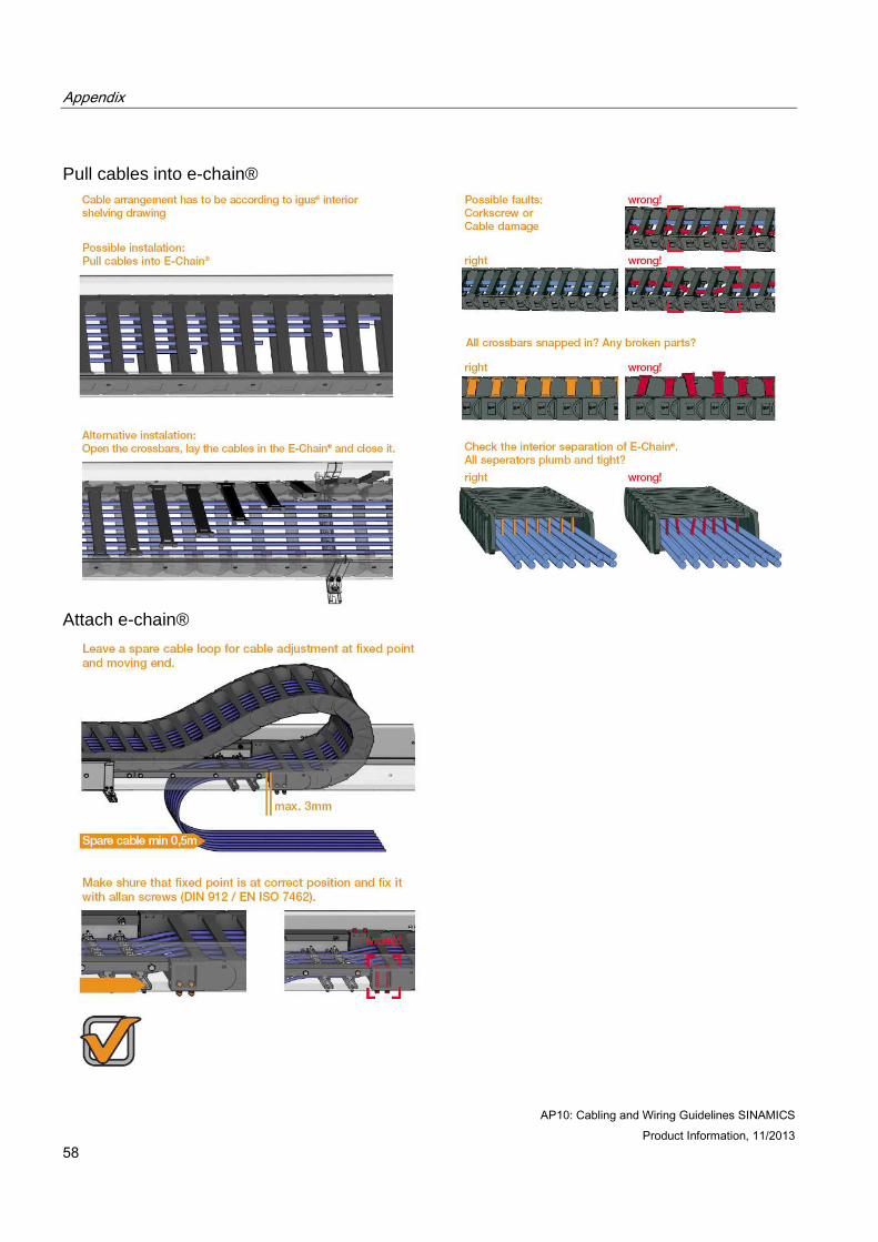
Pull cables into e-chain®
Attach e-chain®
Appendix
AP10: Cabling and Wiring Guidelines SINAMICS Product Information, 11/2013 59
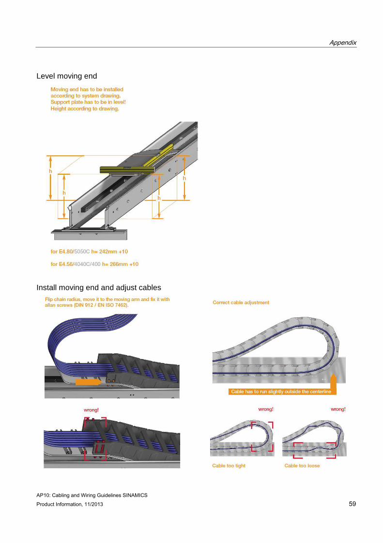
Level moving end
Install moving end and adjust cables
Appendix
AP10: Cabling and Wiring Guidelines SINAMICS Product Information, 11/2013
60
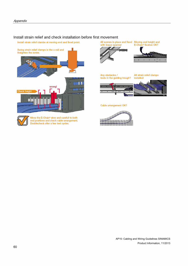
Install strain relief and check installation before first movement

Appendix
AP10: Cabling and Wiring Guidelines SINAMICS Product Information, 11/2013 61
AppendixAppendixAppendixAppendix AAAA A.1A.1A.1A.1 ContactContactContactContact
Application CenterApplication CenterApplication CenterApplication Center
Siemens AG Industry Sector I DT MC CR AP Frauenauracher Str. 80 D-91056 Erlangen
Tel.: +49 9131-98-5233
Fax: +49 9131-98-1424
mailto: [email protected]
www.automation.siemens.com