Embed Size (px)
Citation preview
1
Size-dependent couple stress Timoshenko beam theory
Ali R. Hadjesfandiari, Arezoo Hajesfandiari, Haoyu Zhang, Gary F. Dargush
Department of Mechanical and Aerospace Engineering University at Buffalo, The State University of New York, Buffalo, NY 14260 USA
[email protected], [email protected], [email protected], [email protected]
December 20, 2017
Abstract
In this paper, a new size-dependent Timoshenko beam model is developed based on the consistent
couple stress theory. In the present formulation, the governing equations and corresponding
boundary conditions are obtained. Afterwards, this formulation is used to investigate size-
dependency for several elementary beam problems. Analytical solutions are obtained for pure
bending of a beam and for a cantilever beam with partially and fully clamped boundary conditions.
These analytical results are then compared to the numerical results from a two-dimensional finite
element formulation for the corresponding couple stress continuum problem.
Keywords: Size-dependent mechanics; Couple stress; Curvature, Timoshenko beam; Inflexurable
response
1. Introduction
It is well known that classical continuum mechanics cannot predict the behavior of materials for
very small length scales. While molecular mechanics theories have certainly enjoyed some
success, these approaches are only computationally feasible for collections of particles of quite
limited spatial and temporal extent. This is the true motivation for developing a size-dependent
continuum theory. Mindlin and Tiersten [1] and Koiter [2] developed an initial incomplete version
of couple stress theory (MTK-CST), which suffers from some fundamental inconsistencies, such
as the indeterminacy of the couple-stress tensor, the appearance of the normal component of
couple-traction vector on boundary surfaces, and the consideration of the redundant body couple
2
distribution [3-7]. For linear isotropic elastic materials this theory requires two couple-stress
material parameters, which does not seem attractive from a practical point of view. It turns out
that only one of these elastic couple-stress coefficients appears in the final governing equations
when written in terms of displacements. This in hindsight demonstrates the inconsistency of MTK-
CST.
Without resolving the inconsistencies of MTK-CST, Yang et al. [8] violated fundamental rules of
mechanics to reduce the number of couple-stress material parameters in this theory for linear
isotropic elastic material from two coefficients to only one. In their development, they introduced
an extra artificial equilibrium equation for the moment of couples that has no physical reality, but
apparently makes the couple-stress tensor symmetric. It turns out this proposed theory, called
modified couple stress theory (M-CST), suffers from the same fundamental inconsistencies as
MTK-CST. Furthermore, in this still indeterminate theory (M-CST), the symmetric couple-stress
tensor has a torsional character, which results in size effects for torsional and anticlastic
deformation, but not for bending.
From a practical point of view, even if we ignore the indeterminacy of the couple-stress tensor, it
is generally impossible to satisfy all boundary conditions correctly in many problems using the
original MTK-CST and M-CST. Consequently, MTK-CST and M-CST are not suitable theories
within continuum mechanics for developing new size-dependent formulations. These theories
predict certain deformations, which contradict common sense and do not agree with experiments.
This can be observed in very elementary practical problems. For example, there is no consistent
solution for pure torsion of a circular bar in these theories. We notice that the inconsistent
approximate solutions for pure torsion in these theories predict significant size effect, which does
not agree with experiments [9]. MTK-CST and M-CST also cannot describe pure bending of a
plate properly [10]. Particularly, M-CST predicts no couple-stresses and no size effect for the pure
bending of the plate into a spherical shell. Consequently, MTK-CST and M-CST should not be
used anymore to describe physical reality.
Hadjesfandiari and Dargush [3] and Hadjesfandiari et al. [4] have resolved all inconsistencies and
confusions in the original couple stress theory (MTK-CST) and developed the consistent couple-
3
stress theory (C-CST). In this theory, the couple-stress tensor is skew-symmetric and is
energetically conjugate to the skew-symmetric mean curvature tensor or mean curvature rate
tensor for solids and fluids, respectively. It turns out that the skew-symmetric couple-stress tensor
has a vectorial character, and results in a size effect for bending deformation. For the linear
isotropic elastic solid, there is only one additional material property, l , with the dimensions of
length, which becomes important for problems having characteristic geometry on the order of l
or smaller.
It should be emphasized that C-CST is not a special case of the original MTK-CST in a physical
sense, because a consistent theory should never be classified as a special case of an inconsistent
theory. As we have mentioned, MTK-CST and M-CST suffer from many mathematical and
physical inconsistencies. We also notice that C-CST uses a different curvature tensor from the
original MTK-CST. Contrary to MTK-CST and M-CST, the consistent couple stress theory (C-
CST) predicts consistent results for pure torsion of a circular bar [9] and pure bending of a plate
[10]. Over the last several decades, many different continuum theories have been proposed.
However, only C-CST satisfies all criteria necessary for a consistent size-dependent continuum
mechanics. Therefore, it provides a powerful tool to develop new formulations for different
coupled multi-physics problems, such as piezoelectricity [11] and thermoelasticity [12]. This
theory has also been introduced into fluid mechanics to model size-dependency and perhaps to
contribute to the understanding of turbulence, which affects a cascade of length scales [4].
Consistent couple stress theory (C-CST) has been used recently to study the size effect in some
elastodynamical problems, see Ref. [13-17]. Salter and Richardson [18] developed the governing
equations for the equilibrium of smoothly heterogeneous couple-stress materials by using the
extended Hamilton’s principle. The application of this new consistent couple stress theory in fluid
dynamics can also be found in Ref. [19-21]. However, the number of analytical solutions available
for C-CST within the context of elasticity and viscous fluid is very limited, and therefore,
approximate techniques must be explored. Computational methods such as finite element and
boundary element methods for solving linear two-dimensional couple stress problems have already
been developed, see Ref. [22-30]. Furthermore, the finite difference method in the framework of
size-dependent fluid mechanics has also been implemented by Hajesfandiari et al. [31]. However,
4
for three-dimensional cases, the formulations become formidable and, consequently, other
computational methods should be developed.
Structural mechanics methods offer another possibility to analyze size effects in micro- and nano-
beams, plates and shells. The self-consistency of C-CST makes it suitable for developing size-
dependent structural models, such as beams, plates and shells. However, it should be noticed that
the size-dependent modeling based on structural mechanics methods requires more approximation
than the classical structural modeling. As a result, this approach should be used with more caution.
There have been some recent structural formulations based on C-CST. Alashti and Abolghasemi
[32] have developed an Euler-Bernoulli model to analyze static and free vibration of micro-beams.
Fakhrabadi [33,34] and Fakhrabadi and Yang [35] have investigated the static and dynamic
electromechanical behavior of carbon nano-tubes and nano-beams by using linear and a non-linear
Euler-Bernoulli beam model. Li et al. [36] have used a three-layer Euler-Bernoulli micro-beam
model to study the size-dependent flexoelectric effect under static and dynamic conditions. Beni
[37,38] has studied static deformation, buckling and free vibration of piezoelectric nano-beams
by using linear and non-linear C-CST size-dependent Timoshenko beam models. Keivani et al.
[39-41] have used C-CST based Euler-Bernoulli beam model to investigate the dynamic stability
of beam-type nanotweezers, paddle-type and double-sided NEMS measurement sensors. Zozulya
[42] has developed size-dependent Timosheko and Euler-Bernoulli models for curved rods based
on C-CST. Nejad et al. [43] have investigated free vibration nano-beams made of arbitrary bi-
directional functionally graded materials by using a C-CST Euler-Bernoulli beam mode. Ji and Li
[44] have developed a size-dependent flexoelectric model of Kirchhoff-Love plate bending based
on C-CST to study circular micro-plates in static and dynamic conditions. Aghababaie Beni et al.
[45] have used C-CST to develop a size-dependent plate model to study the dynamic response of
microplates. Additionally, Kheibari and Beni [46], Razavi et al. [47] and Dehkordi and Beni [48]
have analyzed free vibration of single-walled piezoelectric nanotubes, functionally graded
piezoelectric cylindrical nano-shell and nano-cone by using C-CST.
It should be mentioned that there also are many structural formulations based on the other size-
dependent theories, such as modified couple stress theory (M-CST) [8]. For example, Park and
5
Gao [49], Kong et al. [50], Ma et al. [51], Asghari et al. [52,53], Reddy [54], Li et al. [55], Chen
and Meguid [56], Gao [57], Karttunen et al. [58] and Goncalves et al. [59] have developed different
size-dependent beam models. It turns out that the in-plane solutions for M-CST are similar to
those in C-CST and can be found by scaling 2l l . However, the apparent success of M-CST
in describing size effect for isotropic elastic beam bending is not enough to justify M-CST as a
correct theory. It should be noticed that for beam bending the in-plane solutions from all couple
stress theories (MTK-CST, M-CST and C-CST) are the same, but out-of-plane solutions are
different. Beam formulations in these theories are approximate structural analysis methods, which
are expressed by ordinary differential equations for the static case. As a result, these beam models
cannot demonstrate the validity of any of these theories for general three-dimensional boundary
value problems. As previously mentioned, the couple-stresses in M-CST create anticlastic
deformation, which is equivalent to a torsion, not bending. As a result, modified couple stress
theory (M-CST) cannot describe the bending of plates properly [10]. In beam and plate theories
based on M-CST, the normal force-stresses create bending deformation, whereas the couple-
stresses create torsional deformation. Therefore, the apparent success of M-CST for beam
formulations has been very misleading. It is regrettable to see that users of this theory do not
recognize these serious inconsistencies.
In the present work, we utilize consistent couple stress theory (C-CST) and develop a size-
dependent Timoshenko beam model. In this formulation, the governing equations and
corresponding boundary conditions are derived. Then, the formulation is used to investigate the
size-dependent effect for several specific beam problems. Analytical solutions for pure bending
of a beam and for a cantilever beam with partially and fully clamped boundary conditions are
obtained. A number of limiting forms are also explored, including the remarkable inflexurable
case in which bending deformation is entirely suppressed. Many of these analytical results are
then compared to the numerical results from a two-dimensional finite element formulation.
The balance of this paper is structured as follows. In Section 2, we provide an overview of
consistent couple stress theory (C-CST). In Section 3, we develop the size-dependent Timoshenko
beam model based on C-CST, including details on the governing equations and corresponding
boundary conditions. In Section 4, this new model is used to investigate size-dependency in pure
6
bending of a beam, while the bending of a cantilever beam is studied in Section 5. The latter case
includes two distinct partially and fully clamped sets of boundary conditions. Afterwards, in
Section 6, we compare the analytical results to the numerical results from a two-dimensional finite
element formulation for the underlying continuum theory. Finally, we offer some conclusions in
Section 7.
2. Consistent couple stress theory
In couple stress theory, the interaction in the body is represented by force-stress ij and couple-
stress ij tensors. The force and moment balance equations for general couple stress theory under
quasi-static conditions in the absence of body forces are written, respectively, as:
, 0ji j (1)
, 0ji j ijk jk (2)
where ijk is the Levi-Civita alternating symbol.
The force-stress tensor ij is generally non-symmetric and can be decomposed as
ij ij ij (3)
where ij and ij are the symmetric and skew-symmetric parts, respectively. Based on the
consistent couple stress theory (C-CST) [3], the couple-stress tensor ij is skew-symmetrical
ijji (4)
The true couple-stress vector i dual to the pseudo-tensor ij is defined as
kjijki ε 2
1 (5)
For the kinematics, the infinitesimal strain and rotation tensors are defined as
, ,
1
2ij i j j ie u u (6)
7
, ,
1
2ij i j j iu u (7)
respectively. Since the true tensor ij is skew-symmetrical, one can introduce its corresponding
dual pseudo rotation vector as
1
2i ijk kj (8)
The infinitesimal skew-symmetric mean curvature tensor is defined as
ijjijiij ,,, 2
1 (9)
For the most general linear anisotropic elastic material, the constitutive relations are [3]
ijkl kl ijkl klji A e C
(10)
ji ijkl kl klij klB C e
(11)
For a linear isotropic elastic material, these constitutive tensors reduce to
ijkl ij kl ik jl il jkA G G (12)
24ijkl ik jl il jkB Gl (13)
0ijklC (14)
Therefore, in the linear isotropic size-dependent consistent couple stress elasticity, the constitutive
relations are
2kk ij ijij e Ge (15)
28ij ijGl (16)
Here the moduli and G are the Lamé constants for isotropic media in Cauchy elasticity, and G
is also referred to as the shear modulus. These two constants are related by
21 2
G
(17)
where is the Poisson ratio. In addition, we have the relations
8
1 1 2
E
2 1
EG
3 2
1 2
EG
(18-20)
where E is Young’s modulus of elasticity. The constant l is the characteristic material length
scale parameter in the consistent couple stress theory (C-CST), which is absent in Cauchy
elasticity, but is fundamental to small deformation couple stress elasticity.
Furthermore, from (2), we derive
2 2
, 2 jiji i j Gl (21)
As a result, for the total force-stress tensor, we have
2 22 2ji kk ij ij jie Ge Gl (22)
while the elastic energy density function W for material is given by
2 214
2 kk ij ij ij ijW e Ge e Gl (23)
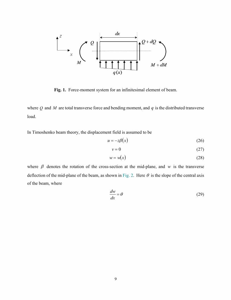
3. Size-dependent Timoshenko beam with couple-stresses
In this section, the couple stress theory is used to reformulate the Timoshenko beam problem to
account for size-dependency in a beam bent in one of its principal planes. For simplicity we may
assume the symmetrical bending in the vertical symmetry plane xz of the beam. The governing
equilibrium equations for an infinitesimal element of the beam, as shown in Fig. 1, are
0dQ
qdx
(24)
0Qdx
dM (25)
9
Fig. 1. Force-moment system for an infinitesimal element of beam.
where Q and M are total transverse force and bending moment, and q is the distributed transverse
load.
In Timoshenko beam theory, the displacement field is assumed to be
xzu (26)
0v (27)
xww (28)
where denotes the rotation of the cross-section at the mid-plane, and w is the transverse
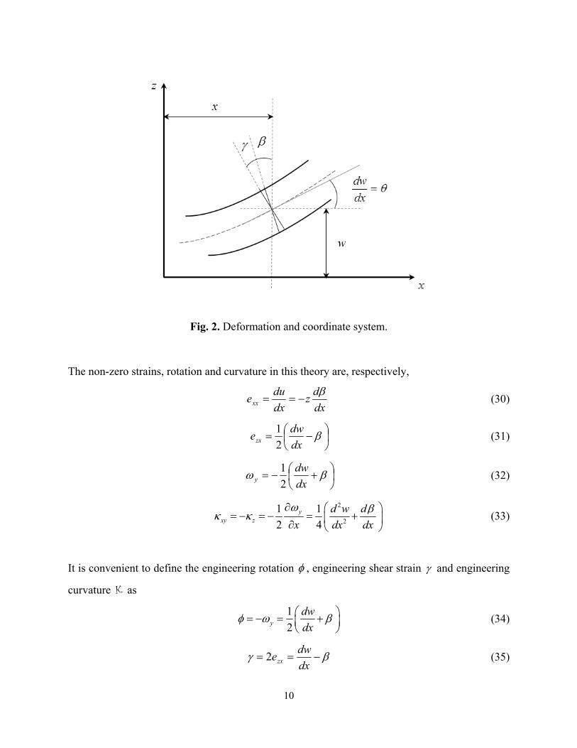
deflection of the mid-plane of the beam, as shown in Fig. 2. Here is the slope of the central axis
of the beam, where
dw
dx (29)
10
Fig. 2. Deformation and coordinate system.
The non-zero strains, rotation and curvature in this theory are, respectively,
dx
dz
dx
duexx
(30)
dx
dwezx 2
1 (31)
dx
dwy 2
1 (32)
2
2
1 1
2 4y
xy z
d w d
x dx dx
(33)
It is convenient to define the engineering rotation , engineering shear strain and engineering
curvature K as
1
2y
dw
dx
(34)
dx
dwezx2 (35)
11
2
2
12
2z
d d w d
dx dx dx
K (36)
According to one-dimensional constitutive relations for slender beams, the non-zero stresses are
zdx
dEEexxxx
(37)
xz
dwG G
dx
(38)
2
2 22
4 2z xy
d w dGl Gl
dx dx
K (39)
Therefore
22 2
2
12
2z
xz
d d d d w dGl Gl
dx dx dx dx dx
K (40)
However, we should notice that the transverse force-stress and couple-stress components are not
uniformly distributed on the cross-section of the beam.
The bending moment M and transverse force Q on the cross-section of the beam can be
decomposed as
MMM (41)
QQQ (42)
where
xx
A
M z dA (43)
xy
A
M dA (44)
and
12
xzA
Q dA (45)
xzA
Q dA (46)
It should be emphasized that since the couple-stress tensor is skew-symmetric, yx xy , the
couple-stress moment M creates bending deformation. However, in the modified couple stress
theory (M-CST), where the couple-stress tensor is symmetric, yx xy , the couple-stress moment
creates torsional deformation [10]. This clearly demonstrates a major inconsistency of M-CST.
We notice that
1 1
2 2z
zxzA A A
dQ dA dA dA
x dx
(47)
which shows
1
2
dMQ
dx
(48)
By using the constitutive relations, we obtain
dx
dEIM
(49)
2
2 22
4 2d w d
M k GAl k GAldx dx
K (50)
s s
dwQ k GA k GA
dx
(51)
and as a result
22
2
1
2
dM d d w dQ k GAl
dx dx dx dx
(52)
We notice that components M and Q are the bending moment and transverse force due to the
normal force-stress and symmetric shear force-stress, respectively, as in classical Timoshenko
13
beam theory. However, there are additional components M and Q , which are due to the effect
of couple-stress xy and skew-symmetric shear force-stress xz , respectively, in the couple-stress
Timoshenko beam theory. The transverse component force Q can be called the couple-stress
induced transverse force. Here A and I are the area and second moment of area of the beam
cross-section, and the coefficient sk is the shear coefficient, which accounts for the non-uniformity
of the symmetric shear stress xz over the beam cross-section. We have also introduced the
correction factor k to account for the non-uniformity of the couple stress xy over the beam
cross-section. It should be noticed that in couple stress theory the coefficients sk and k depend
on Poisson ratio and the length scale parameter l . However, we still use the value of sk from
the classical theory [60] as an approximation.
It should be noticed that the results in this formulation can be used for the cylindrical bending of
a wide flat plate with width b and height h , when b h . It is only necessary to replace the
Young’s modulus E by 21
E
in (49) and take 1k .
Consequently, we obtain the following relations for the total bending moment M and the
transverse force Q :
22
22
d d w dM EI k GAl
dx dx dx
(53)
22
2s
dw d d w dQ k GA k GAl
dx dx dx dx
(54)
By substituting the expressions for Q and M in the equilibrium equations (24) and (25), we obtain
the equilibrium equations
22
20s
d dw d d w dk GA k GAl q
dx dx dx dx dx
(55)
14
22
20s
d d d w d dwEI k GAl k GA
dx dx dx dx dx
(56)
The total potential energy for this Timoshenko beam with couple-stresses is given by
0 000 0
L LLL L
Udx qwdx M M Qw (57)
where
2
2 2 21 12
2 2 s
dU EI k GA k GAl
dx
K (58)
is the elastic energy per unit length of the deformed beam, and the term 0
L
qwdx is the potential
of the transverse load q . We notice that the terms 0L
M , 0
LM and 0
LQw are the
potential of the force-stress bending moment M , the couple-stress bending moments M , and
the total transverse force Q at the ends of the beam, respectively. Consequently, the total potential
energy can be written as
22 2 22
20
0000
1 1 1
2 2 2
L
s
LLL L
d dw d w dEI k GA k GAl dx
dx dx dx dx
dwpwdx M M Qw
dx
(59)
where we have used the relation 1
2
dw
dx
. We notice that the total bending moment on the
cross-section of the beam has been decomposed to two components M and M , where
22
2
1
2
d d w dM M M EI k GAl
dx dx dx
(60)
22
2
1
2
d w dM M k GAl
dx dx
(61)
15
Therefore, the transverse displacement degree of freedom w is energy conjugate to the total
transverse force Q , where
Q Q Q w (62)
It is also seen that in this formulation, the slope dx
dw and rotation are independent degrees
of freedom, and their conjugate bending moments are
1
21
2
M M M
dwM M
dx
(63)
The equilibrium corresponds to equating the first variation to zero, that is,
0 (64)
This is the weak formulation or virtual work theorem for this model, which can be written as
2
0 0 0
0 000
4L L L
s
LL L L
d dEI dx GAk dx GAk l dx
dx dx
p wdx M M Q w
K K (65)
It is seen that for the essential (geometrical) boundary conditions, we can specify )(xw , dx
dw
or )(x . For the natural boundary conditions, we may specify Q , M or M .
It should be noticed that in classical Timoshenko beam theory )(xw and )(x are the kinematical
variables or the degrees of freedom, whereas the slope dx
dw is not a fundamental variable.
However, in size-dependent couple stress Timoshenko theory, dx
dw becomes a degree of
16
freedom, which accounts for a portion of the engineering rotation 1
2
dw
dx
. This shows
that the couple stress Timoshenko beam theory combines the features of classical Timoshenko and
Euler-Bernoulli beam theories.
Now we use this formulation to obtain analytical solutions for the uniform cross-section micro-
beam under different loadings conditions. We notice that for a beam with uniform cross-section,
the total bending moment M and the shear force Q become
2
2 22
2 2d d w
M EI k GAl k GAldx dx
(66)
3 22 2
3 2s s
dw d w dQ GA k k l GA k k l
dx dx dx
(67)
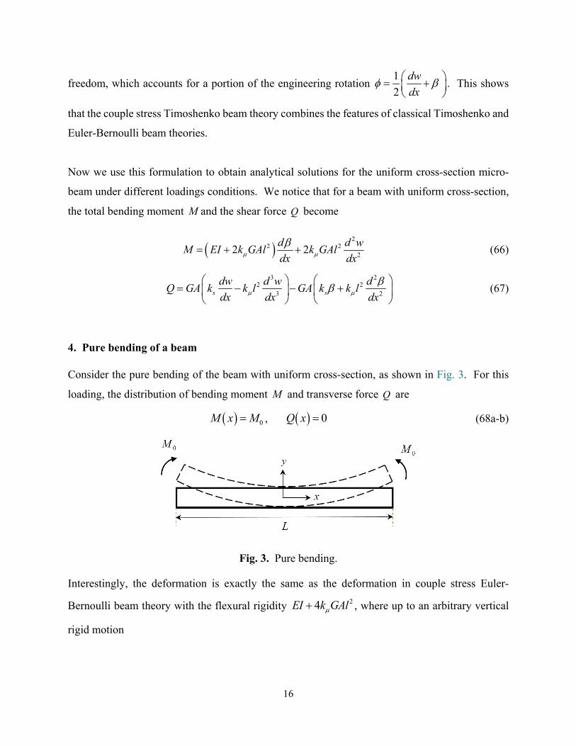
4. Pure bending of a beam
Consider the pure bending of the beam with uniform cross-section, as shown in Fig. 3. For this
loading, the distribution of bending moment M and transverse force Q are
0M x M , 0Q x (68a-b)
Fig. 3. Pure bending.
Interestingly, the deformation is exactly the same as the deformation in couple stress Euler-
Bernoulli beam theory with the flexural rigidity 24EI k GAl , where up to an arbitrary vertical
rigid motion
17
20
22 4
Mw x x
EI k GAl
(69)
024
Mdwx
dx EI k GAl
(70)
We notice that this deformation corresponds to the fully clamped condition at 0x , where
0w , 0 , 0 dx
dw (71a-c)
For this deformation there is no engineering shear strain, 0 , and the continuum mechanical
rotation and engineering curvature K become
02
1
2 4
Mdwx
dx EI k GAl
(72)
024
Md
dx EI k GAl
K (73)
For the force- and couple-stress bending moments, we obtain
024
d EIM EI M
dx EI k GAl
(74)
2
202
44
4
k GAlM k GAl M
EI k GAl
K = (75)
where
0M M M (76)
However, the shear and couple-stress induced transverse forces vanish, that is, 0Q Q .
We notice that as l increases, or the beam become more slender, the couple stress bending moment
M increases. This shows contrary to classical beam theory, for micro-beams, the load is carried
more by couple-stresses than normal force-stresses.
18
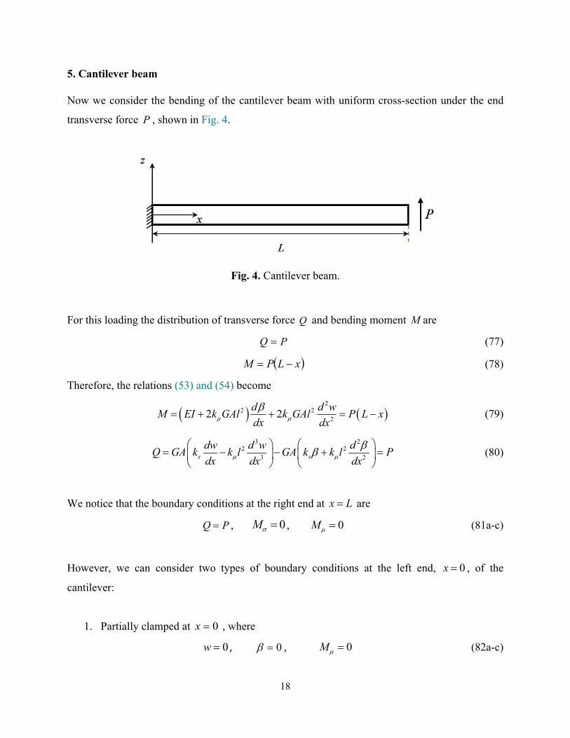
5. Cantilever beam
Now we consider the bending of the cantilever beam with uniform cross-section under the end
transverse force P , shown in Fig. 4.
Fig. 4. Cantilever beam.
For this loading the distribution of transverse force Q and bending moment M are
PQ (77)
xLPM (78)
Therefore, the relations (53) and (54) become
2
2 22
2 2d d w
M EI k GAl k GAl P L xdx dx
(79)
3 22 2
3 2s s
dw d w dQ GA k k l GA k k l P
dx dx dx
(80)
We notice that the boundary conditions at the right end at x L are
Q P , 0M , 0M (81a-c)
However, we can consider two types of boundary conditions at the left end, 0x , of the
cantilever:
1. Partially clamped at 0x , where
0w , 0 , 0M (82a-c)
19
2. Fully clamped at 0x , where
0w , 0 , 0dw
dx (83a-c)
By integrating the relation (79) once and noticing that 0 and 0w at 0x in both cases, we
obtain
2 2 2
0
12 2
2
dw dwEI k GAl k GAl P Lx x
dx dx
(84)
Now based on the fact that if the value of 0
dw
dx is known or not, we consider partially or fully
clamped cases in the following subsections.
5.1. Partially clamped cantilever beam
In this case the slope 0
dw
dx is not yet known. Therefore, equation (84) can be written as
22
2 20
21
2 2 2
EI k GAldw dw PLx x
dx dx k GAl k GAl
(85)
By some manipulation, we obtain the relation
23 22 2 2 2
3 2 2 20
21
2 2 2s s s
EI k GAlk k kdw d w dw P dl Lx x l l
dx k dx dx k GAl k k GAl k dx
(86)
By using this relation in (80), we obtain the second order linear differential equation for as
2
2 2 2 2 22
0
14 2
2s s
k kd dwEI k GAl EI l k GAl P Lx x P l
k dx dx k
(87)
By defining the new length scale parameter
24s
k EIl
k EI k GAl
l = (88)
20
the solution to this boundary value problem for is given by
202
cosh1
14 2 cosh
L xP
Lx x aLEI k GAl
l
l
(89)
where we have used the boundary condition 0 at 0x . By using the boundary condition
0d
M EIdx
at x L , we obtain for the coefficient 0a
2 2
20 2 22
0
2 22
44s
k EI k GAl k GAl dwa P l
k EI k GAl dxEI k GAl
(90)
The value of 0
dw
dx is obtained by enforcing the boundary condition
22
22 0
d w dM k Gl
dx dx
at 0x . By using the expressions (85) and (89), we obtain
2
2 2 22 2
d w d P EI dL x
dx dx k GAl k GAl dx
(91)
which shows that
d PL
dx EI
at 0x (92)
By using this boundary value in (89), we obtain the explicit relation
2
0 2
4
4 tanh
k GAla PL
LEI EI k GAl
l
l
(93)
As a result, the relation (90) gives
2
20
22
4tanh s
EI k GAldw PL PLdx EI k GA EI k GAl
l
l
(94)
Consequently, for and dw
dx , we obtain
21
2
22 2
cosh41
14 2 4 tanh cosh
L xk GAlP
Lx x PLL LEI k GAl EI EI k GAl
l l
l l
(95)
2
2
22
2 2
2 2
4 tanh
cosh21
2 14 2 4 tanh cosh
s
EI k GAldw P PLLdx k GA EI k GAl EI
L xEI k GAlP PL
Lx xL LEI k GAl EI EI k GAl
l
l
l l
l l
(96)
By integrating the relation (96) and noticing 0w at 0x , we obtain the expression for the
transverse deflection w as
22 3
2 2
2
2
2 2 1 1
4 4 2 6tanh
sinh22
tanh4 tanh cosh
s
EI k GAlP PL Pw x Lx x
Lk GA EI k GAl EI EI k GAl
L xEI k GAlPL L
xL LEI EI k GAl
l
l
l ll ll
l l
(97)
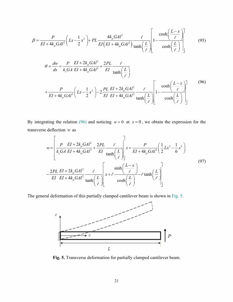
The general deformation of this partially clamped cantilever beam is shown in Fig. 5.
Fig. 5. Transverse deformation for partially clamped cantilever beam.
22
For the corresponding engineering shear strain , rotation and engineering curvature K , we
obtain
2
2
cosh2
24
sinhs
L xEI k GAldw P PL
Ldx k GA EI k GAl EI
ll
l
(98)
2
2
22 2
21
2 2 4tanh
cosh1
14 2 4 tanh cosh
s
EI k GAldw PL PLdx EI k GA EI k GAl
L xP PL
Lx xL LEI k GAl EI k GAl
l
l
l l
l l
(99)
2 2
sinh
4 4sinh
L xd P PL
L xLdx EI k GAl EI k GAl
K = l
l
(100)
As a result, the force- and couple-stress bending moments become
2
2 2
sinh4
4 4 sinh
dM EI
dxL x
k GAlEIP L x PL
LEI k GAl EI k GAl
l
l
(101)
2
2 2
2 2
4
sinh4 4
4 4sinh
dM k GAl
dxL x
k GAl k GAlP L x PL
LEI k GAl EI k GAl
l
l
(102)
For the shear and couple-stress induced transverse forces, we obtain
23
2
2
cosh2
24
sinh
s
s
Q k GA
L xEI k GAl k GAL
P PLEI k GAl EI
ll
l
(103)
2
2
1
2
cosh2
24 sinh
s
dMQ
dxL x
k GAl k GALP P
LEI k GAl EI
ll
l
(104)
Interestingly, we notice that
Q Q P Q (105)
( )M M P L x M (106)
For the tip deflection of the beam, we have
3
2
2 2 222
22 22
3 4
2 2 222
4 44 tanhs s
PLw L
EI k GAl
EI k GAl EI k GAl k k GAlPL PLPL l
Lk GA EI k GAl k EI EI k GAlEI k GAl
l
l
(107)
Therefore, the spring constant or stiffness P
K
of the cantilever becomes
2 2 23 2
222 22 2
1
2 2 222
4 43 4 4 tanhs s
KEI k GAl EI k GAl k k GAlL L L
L lLk GA EI k GAl k EI EI k GAlEI k GAl EI k GAl
l
l(108)
We may define the effective flexural rigidity 3
3eff
KLE I based on the stiffness in classical Euler-
Bernoulli beam theory as
24
3
2 2 22
22 2 2 2 22
1
31
2 2 21 3 6 64 4 44 tanh
eff
s s
E I KL
EI k GAl EI k GAl k k GAl LlLEI k GAl k GAL EI k GAl L k EI EI k GAlEI k GAl
l
l
(109)
Therefore, the non-dimensional stiffness or flexural rigidity R is
3
2 2 22
22 2 2 2 22
31
2 2 123 64 4 44 tanh
eff
s s
E I KLR
EI EI
EI k GAl EI k GAl k k GAlEI EI EI LlLEI k GAl k GAL EI k GAl L k EI k GAlEI k GAl
l
l
(110)
We notice that when the length of beam becomes larger and larger, the effective flexural rigidity
approaches its value in couple stress Euler-Bernoulli beam theory, where
L 24eff LE I EI k GAl
(111)
This means that for longer beams the transverse deformation of the beam is negligible. Now we
consider the limiting cases based on the length scale parameter l as follows.
5.1.1. Classical theory 0l
When the couple-stress effects are neglected, that is 0l , we notice that 0l . As a result, the
solution reduces to the classical Timoshenko solution, where
2 31 1
2 6 s
P Pw Lx x x
EI k GA
(112)
21
2 s
dw P PLx x
dx EI k GA
(113)
25
22
1
4 2
PLx x
EI k GAl
(114)
s
P
k GA (115)
21 1
2 2 2 s
dw P PLx x
dx EI k GA
(116)
Interestingly, we notice
Q P Q (117)
( )M P L x M (118)
For the stiffness and the effective flexural rigidity, we obtain
0 3
1
3 s
KL LEI k GA
(119)
3
0
0
2
33 1eff
s
K L EIE I
EIk GAL
(120)
We should notice that the effective flexural rigidity 0effE I in classical Timoshenko beam theory
is apparently size-dependent and less than its corresponding value EI in classical Euler-Bernoulli
beam theory. This classical size-dependency is the result of the peculiar definition of 0effE I that
includes the effect of shear deformation in classical beam theory. For this case, the normalized
effective flexural rigidity is
0
0
2
13
1
eff
s
E IR
EIEIk GAL
(121)
which is less than one, that is 0 1R .
26
5.1.2. Inflexurable couple stress theory l
When all dimensions of the beam are smaller than the length scale parameter l , the couple-stress
effect becomes dominant. Interestingly, we can consider the limiting case l , where the
engineering curvature 0K and l l , with
1
2 s
EI
k GAl = (122)
This interesting case may be called inflexurable, where there is no continuum mechanical
curvature. Therefore, the solution reduces to
sinh
12 4
tanh sinhs s
L x
P PL PLw x
k GA EI k GAL L
ll
l l
(123)
cosh1
2 4tanh sinhs s
L x
dw P PL PL
dx k GA EI k GAL L
lll
l l
(124)
cosh
1
tanh cosh
L x
PL
EI L L
ll
l l
(125)
cosh
22
tanh coshs
L x
dw P PL
dx k GA EI L L
ll
l l
(126)
1
2 4tanh s
dw PL P
dx EI k GAL
l
l
(127)
0d
dx
K (128)
27
We notice that although the slope dw
dx and are not constant, the continuum mechanical
rotation is constant and the engineering curvature K becomes zero. For this inflexurable case,
the force- and couple-stress bending moments approach, respectively, to the forms
sinh
sinh
L x
dM EI PL
dx L
l
l
(129)
sinh
sinh
L x
M P L x PLL
l
l
(130)
and the shear and couple-stress induced transverse forces become, respectively,
cosh1
12
sinh
L x
LQ P
L
l
ll
(131)
cosh1
12
sinh
L x
LQ P
L
l
ll
(132)
The tip deflection of the beam approaches to
23
4tanhs
PL PL
k GA EI L
l
l
(133)
and the stiffness becomes
2
1
34
tanhs
KL L
k GA EI L
l
l
(134)
28
Therefore, for this case, the effective flexural rigidity and its normalized value are
3
2
19 33
4tanh
eff
s
K LE I
k GAL EIL L
l
l
(135)
3
2
19 33
4tanh
eff
s
E I K LR
EIEI EIk GAL L L
l
l
(136)
respectively.
When the beam is so long that L l , we have tanh 1L
l. Therefore, the deformation can
be approximately represented by
12 4
x
s s
P PL PLw x e
k GA EI k GA
ll (137)
1
2 4
x
s s
dw P PL PLe
dx k GA EI k GA
lll
(138)
1x
PLe
EI
ll (139)
12
xP L
Q e
l
l (140)
12
xP L
Q e
l
l (141)
x
M P e
ll (142)
x
M P L x P e
ll (143)
29
The relation (137) shows that except a small region near to the fixed end, the deflection is
practically a straight line, where we have
34 2s s
PL P PLw x x
k GA k GA EI
l l (144)
Therefore, we may approximate the relations (134)-(136) by the expressions
2 2
2s
EIK k EIGA
L L
l
(145)
2
3 3eff s
EIE I L L k EIGA
l
(146)
1 2
3 3
eff sE I k GA
R L LEI EI
l
(147)
5.2. Fully clamped cantilever beam
In this case, there is no slope at 0x , that is 0
0dw
dx . As a result, the equation (85) gives
22
2 2
21
2 2 2
EI k GAldw PLx x
dx k GAl k GAl
(148)
From this relation, we obtain
23 22 2 2 2
3 2 2 2
21
2 2 2s s s
EI k GAlk k kdw d w P dl Lx x l l
dx k dx k GAl k k GAl k dx
(149)
Therefore, by using this in (81), the second order linear differential equation for becomes
2
2 2 2 22
14
2s s
k kdEI k GAl EI l P Lx x P l
k dx k
(150)
By using the boundary conditions 0 at 0x , and 0d
M EIdx
at x L , we obtain the
solution as
30
22 2
22 2
cosh21
2 14 2 4 coshs
L xk EI k GAlP
Lx x P lLEI k GAl k EI k GAl
l
l
(151)
By using this expression in (148), we obtain the relation for the slope dw
dx as
22
222 2
cosh211
4 2 4 coshs
L xEI k GAldw P P
Lx xLdx EI k GAl k GA EI k GAl
l
l
(152)
By integrating this relation and noticing 0w at 0x , we obtain the transverse deflection w as
22
2 322 2
sinh21 1tanh
4 2 6 4 coshs
L xEI k GAlP P L
w Lx x xLEI k GAl k GA EI k GAl
ll ll
l
(153)
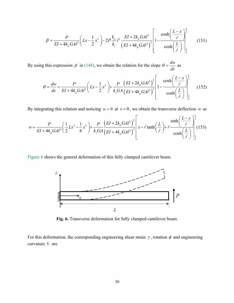
Figure 6 shows the general deformation of this fully clamped cantilever beam.
Fig. 6. Transverse deformation for fully clamped cantilever beam.
For this deformation, the corresponding engineering shear strain , rotation and engineering
curvature K are
31
2
2
cosh2
14 coshs
L xEI k GAldw P
Ldx k GA EI k GAl
l
l
(154)
22
22 2
cosh21 1
12 4 2 2 4 coshs
L xEI k GAldw P P EI
Lx xLdx EI k GAl k GA EI k GAl
l
l
(155)
2
22 2
sinh21 1
4 2 2 4 coshs
L xEI k GAld P P EI
L xLdx EI k GAl k GA EI k GAl
K ll
l
(156)
For the force- and couple-stress bending moment, we have, respectively,
22
22 2
sinh2 2
4 4 coshs
dM EI
dxL x
EI EI k GAlkEI lP L x P
LEI k GAl k EI k GAl
ll
l
(157)
2
22 2
22 2
4
sinh24 2
4 4 coshs
M k GAl
L xEI EI k GAlk GAl k l
P L x PLEI k GAl k EI k GAl
K
ll
l
(158)
For the shear and couple-stress induced transverse forces, we obtain
2
2
cosh2
14 cosh
s
L xEI k GAl
Q k GA PLEI k GAl
l
l
(159)
32
2 2
2 2
1
2
cosh2 2
4 4 cosh
dMQ
dxL x
k GAl EI k GAlP P
LEI k GAl EI k GAl
l
l
(160)
where
Q Q P Q (161)
( )M M P L x M (162)
For the tip deflection of the beam, we obtain
223
22 2
21tanh
3 4 4s
EI k GAlPL P Lw L L
EI k GAl k GA EI k GAl
ll
(163)
As a result, for the spring constant or stiffness of the cantilever in this case, we obtain
223
22 2
1
21 tanh
3 4 4s
KEI k GAlL L L
k GA LEI k GAl EI k GAl
ll
(164)
For the effective flexural rigidity based on the stiffness in classical Euler-Bernoulli beam theory,
we have
3
22
22 2 2
31
21 1 31 tanh
4 4
eff
s
KLE I
EI k GAl LEI k GAl k GA L LEI k GAl
ll
(165)
Therefore, the non-dimensional stiffness or flexural rigidity becomes
3
22
22 2 2
31
231 tanh
4 4
eff
s
E I KLR
EI EI
EI k GAlEI EI LEI k GAl k GA L LEI k GAl
ll
(166)
33
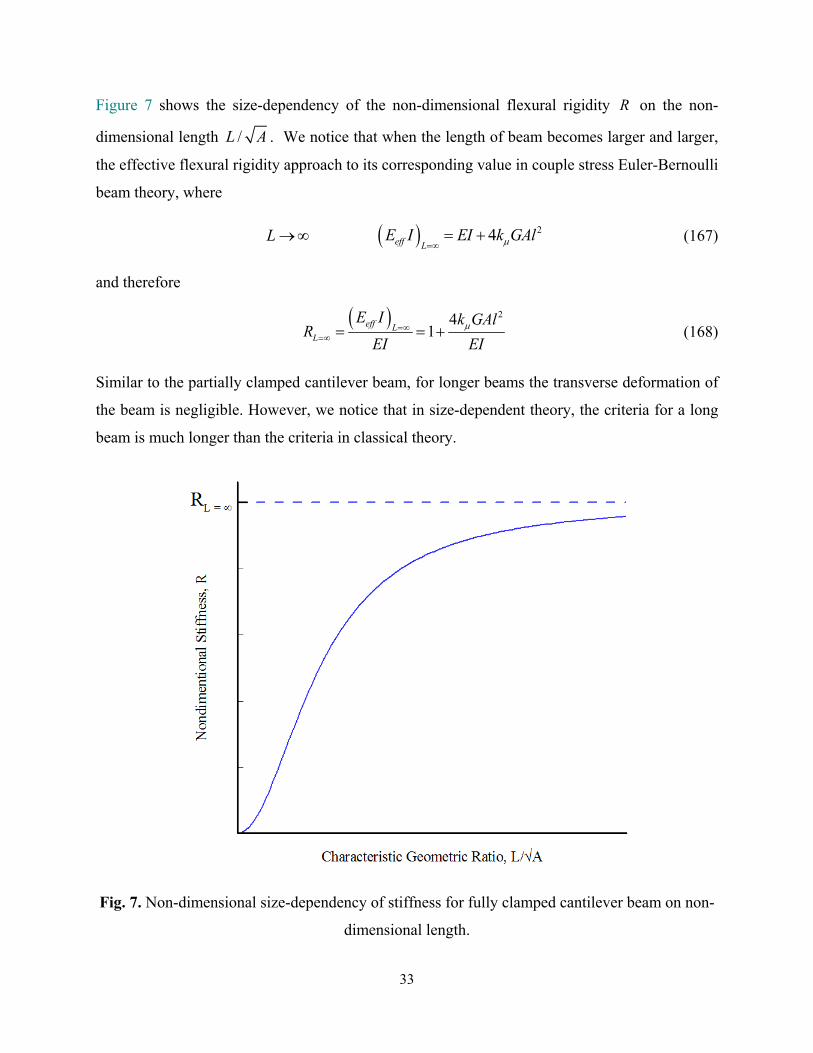
Figure 7 shows the size-dependency of the non-dimensional flexural rigidity R on the non-
dimensional length /L A . We notice that when the length of beam becomes larger and larger,
the effective flexural rigidity approach to its corresponding value in couple stress Euler-Bernoulli
beam theory, where
L 24eff LE I EI k GAl
(167)
and therefore
24
1eff L
L
E I k GAlR
EI EI
(168)
Similar to the partially clamped cantilever beam, for longer beams the transverse deformation of
the beam is negligible. However, we notice that in size-dependent theory, the criteria for a long
beam is much longer than the criteria in classical theory.
Fig. 7. Non-dimensional size-dependency of stiffness for fully clamped cantilever beam on non-
dimensional length.
34
For this fully clamped case, we also consider the limiting cases based on the length scale parameter
l as follows.
5.2.1. Classical theory 0l
When the couple-stress effects are neglected, that is 0l , the solution reduces to the classical
Timoshenko solution as discussed before in Section 5.1.1.
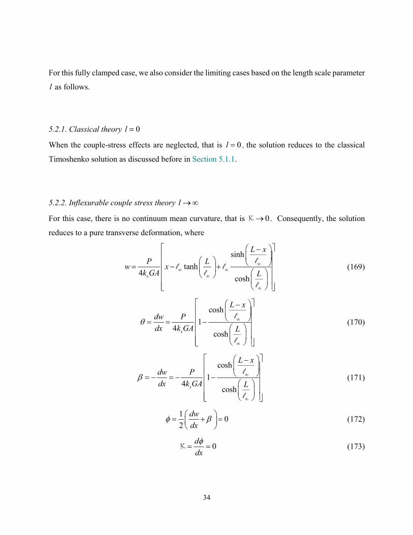
5.2.2. Inflexurable couple stress theory l
For this case, there is no continuum mean curvature, that is 0K . Consequently, the solution
reduces to a pure transverse deformation, where
sinh
tanh4
coshs
L x
P Lw x
k GA L
ll l
ll
(169)
cosh
14
coshs
L x
dw P
dx k GA L
l
l
(170)
cosh
14
coshs
L x
dw P
dx k GA L
l
l
(171)
1
02
dw
dx
(172)
0d
dx
K (173)
35
cosh
2 12
coshs
L x
dw P
dx k GA L
l
l
(174)
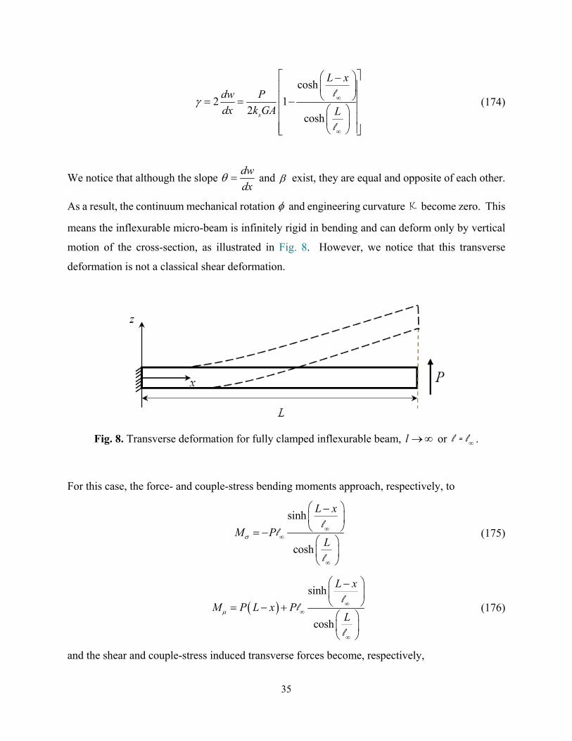
We notice that although the slope dw
dx and exist, they are equal and opposite of each other.
As a result, the continuum mechanical rotation and engineering curvature K become zero. This
means the inflexurable micro-beam is infinitely rigid in bending and can deform only by vertical
motion of the cross-section, as illustrated in Fig. 8. However, we notice that this transverse
deformation is not a classical shear deformation.
Fig. 8. Transverse deformation for fully clamped inflexurable beam, l or l = l .
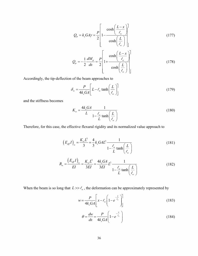
For this case, the force- and couple-stress bending moments approach, respectively, to
sinh
cosh
L x
M PL
ll
l
(175)
sinh
cosh
L x
M P L x PL
ll
l
(176)
and the shear and couple-stress induced transverse forces become, respectively,
36
cosh
12
coshs
L x
PQ k GA
L
l
l
(177)
cosh1
12 2
cosh
L xdM P
Qdx L
l
l
(178)
Accordingly, the tip-deflection of the beam approaches to
tanh4 s
P LL
k GA
l
l (179)
and the stiffness becomes
4 1
1 tanh
sk GAK
L LL
ll
(180)
Therefore, for this case, the effective flexural rigidity and its normalized value approach to
3
24 1
3 31 tanh
eff s
K LE I k GAL
LL
ll
(181)
324 1
3 31 tanh
eff sE I k GAK L
R LEI EI EI L
L
ll
(182)
When the beam is so long that L l , the deformation can be approximately represented by
14
x
s
Pw x e
k GA
ll (183)
14
x
s
dw Pe
dx k GA
l (184)
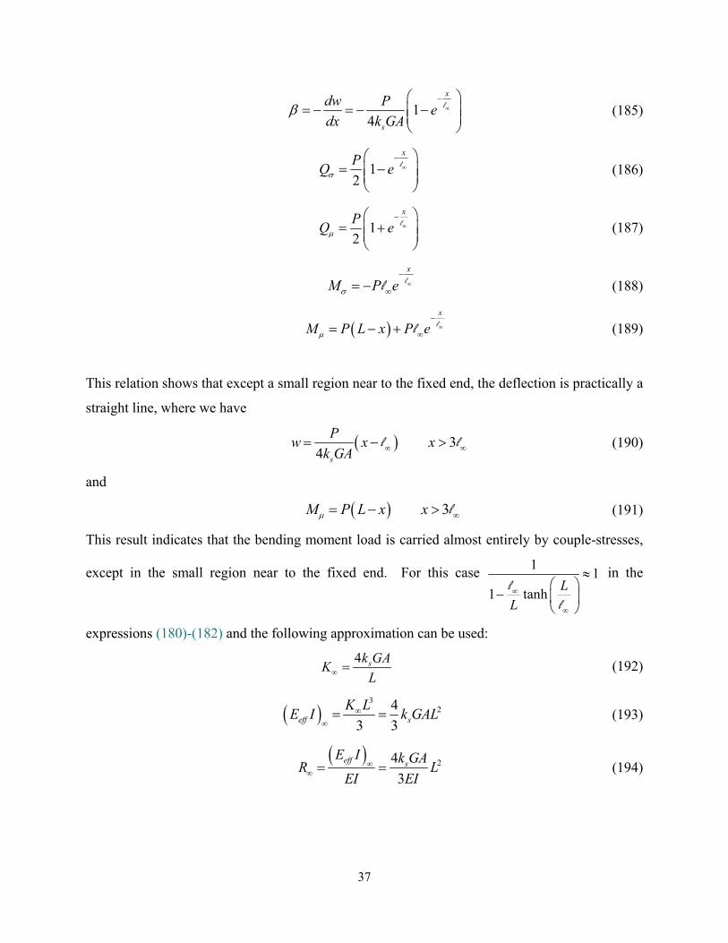
37
14
x
s
dw Pe
dx k GA
l (185)
12
xP
Q e
l (186)
12
xP
Q e
l (187)
x
M P e
ll (188)
x
M P L x P e
ll (189)
This relation shows that except a small region near to the fixed end, the deflection is practically a
straight line, where we have
34 s
Pw x x
k GA l l (190)
and
3M P L x x l (191)
This result indicates that the bending moment load is carried almost entirely by couple-stresses,
except in the small region near to the fixed end. For this case 1
1
1 tanhL
L
ll
in the
expressions (180)-(182) and the following approximation can be used:
4 sk GAK
L (192)
3
24
3 3eff s
K LE I k GAL
(193)
24
3
eff sE I k GA
R LEI EI
(194)
38
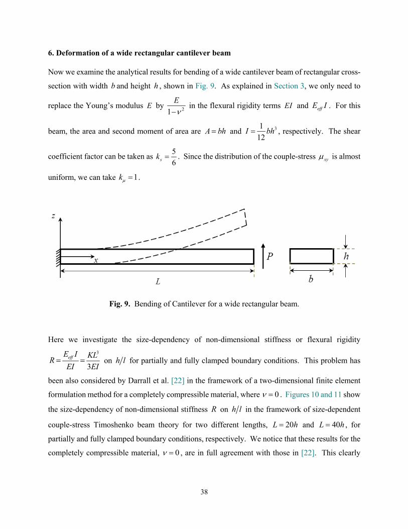
6. Deformation of a wide rectangular cantilever beam
Now we examine the analytical results for bending of a wide cantilever beam of rectangular cross-
section with width b and height h , shown in Fig. 9. As explained in Section 3, we only need to
replace the Young’s modulus E by 21
E
in the flexural rigidity terms EI and effE I . For this
beam, the area and second moment of area are A bh and 31
12I bh , respectively. The shear
coefficient factor can be taken as 5
6sk . Since the distribution of the couple-stress xy is almost
uniform, we can take 1k .
Fig. 9. Bending of Cantilever for a wide rectangular beam.
Here we investigate the size-dependency of non-dimensional stiffness or flexural rigidity
3
3effE I KL
REI EI
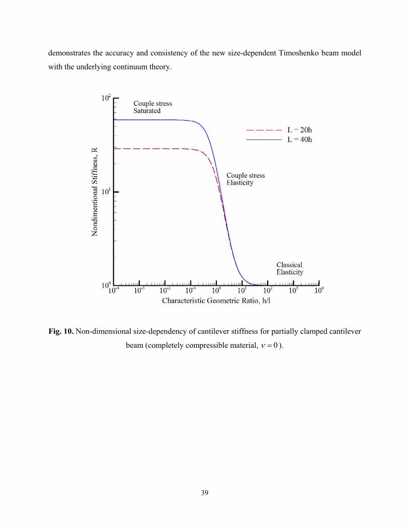
on h l for partially and fully clamped boundary conditions. This problem has
been also considered by Darrall et al. [22] in the framework of a two-dimensional finite element
formulation method for a completely compressible material, where 0 . Figures 10 and 11 show
the size-dependency of non-dimensional stiffness R on h l in the framework of size-dependent
couple-stress Timoshenko beam theory for two different lengths, 20L h and 40L h , for
partially and fully clamped boundary conditions, respectively. We notice that these results for the
completely compressible material, 0 , are in full agreement with those in [22]. This clearly
39
demonstrates the accuracy and consistency of the new size-dependent Timoshenko beam model
with the underlying continuum theory.
Fig. 10. Non-dimensional size-dependency of cantilever stiffness for partially clamped cantilever
beam (completely compressible material, 0 ).
40
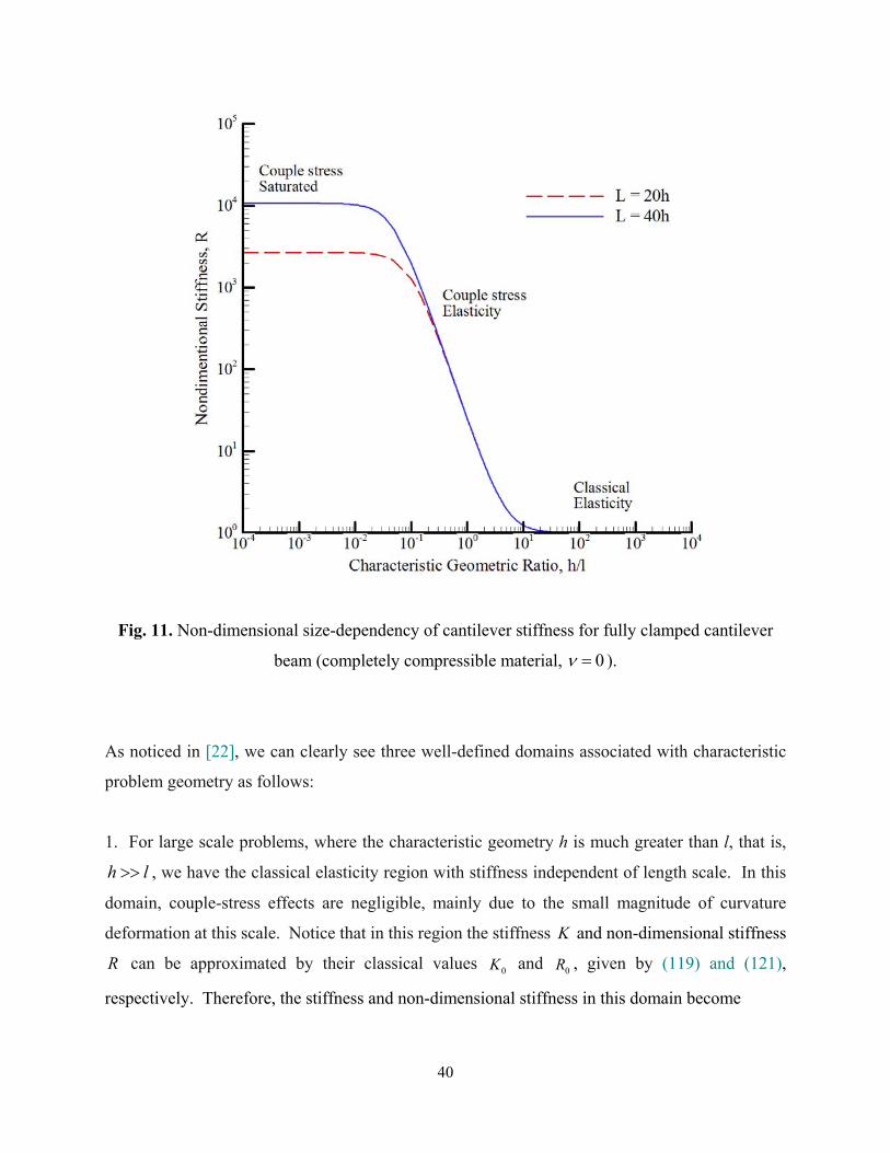
Fig. 11. Non-dimensional size-dependency of cantilever stiffness for fully clamped cantilever
beam (completely compressible material, 0 ).
As noticed in [22], we can clearly see three well-defined domains associated with characteristic
problem geometry as follows:
1. For large scale problems, where the characteristic geometry h is much greater than l, that is,
h l , we have the classical elasticity region with stiffness independent of length scale. In this
domain, couple-stress effects are negligible, mainly due to the small magnitude of curvature
deformation at this scale. Notice that in this region the stiffness K and non-dimensional stiffness
R can be approximated by their classical values 0K and 0R , given by (119) and (121),
respectively. Therefore, the stiffness and non-dimensional stiffness in this domain become
41
0 2 23
2
3 1
14 s
EIK
Eh hLk G L
, 0 2 2
2
1
14 s
REh hk G L
(195)
We notice that for this case, when the beam is very long, i.e., L h , these relations for 0K and
0R approach the corresponding values in classical Euler-Bernoulli beam theory
0 3
3EIK
L , 0 1R (196)
2. When the characteristic geometry for this problem is on the order of l , we enter the transitional
couple-stress domain. For this cantilever problem, it is clear from Figs. 10 and 11 that couple-
stress effects become significant for characteristic geometry with 10.h l In this couple-stress
domain, there is an increase in flexural stiffness, which has a significant effect on the overall
effective stiffness K of the body.
3. Finally, for very small values of h l , i.e., h l , we have a domain that is couple-stress
“saturated” in both Figs. 10 and 11. This means the flexural stiffness due to couple-stress effects
has increased to the level where mean curvature is suppressed. We notice that in this nearly
inflexurable domain, the deformation of the cantilever beam can be approximated by the
inflexurability condition, where
1
4 3 2 6s s
h E h
k G k
l = = (197)
Curiously, when the beam is very long, i.e., L h , we have L l . As a result, the relations
(145), (147), (192) and (194) give the stiffness and non-dimensional stiffness in the couple stress
“saturated” domains as
2
2
6
6 1skEb h
KL
, 241
3 1sk L
Rh
partially clamped (198)
4 s
hK k Gb
L , 2
2
8
1sk L
Rh
fully clamped (199)
42
For the completely compressible case 0 and 5 6sk , we obtain
2
25
6
Eb hK
L , 2
53
LR
h partially clamped (200)
10
3
hK Gb
L , 2
2
20
3
LR
h fully clamped (201)
Therefore, for sufficiently small h l ratios, an increase in total stiffness is observed, where the
stiffness scales with 2
1
L and
1
L for partially and fully clamped conditions, respectively.
Interestingly, these results have been concluded by Darrall et al. [22] based on numerical
experiments.
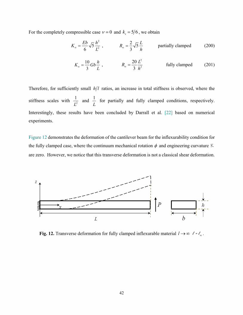
Figure 12 demonstrates the deformation of the cantilever beam for the inflexurability condition for
the fully clamped case, where the continuum mechanical rotation and engineering curvature K
are zero. However, we notice that this transverse deformation is not a classical shear deformation.
Fig. 12. Transverse deformation for fully clamped inflexurable material l l = l .
43
7. Conclusions
Based on consistent couple stress theory (C-CST), we have developed a size-dependent
Timoshenko beam model. The corresponding governing equations and boundary conditions for
this model have been obtained. We notice in this formulation the transverse displacement w , the
slope dx
dw and rotation are the degrees of freedom with energy conjugates Q ,
1
2M M
and 1
2M M M , respectively. This clearly shows that the present couple stress
Timoshenko beam theory combines the features of classical Timoshenko and Euler-Bernoulli
beam theories.
Furthermore, this Timoshenko beam model has been employed to obtain analytical solutions for
pure bending of a beam and for a cantilever beam with partially and fully clamped boundary
conditions. For the cantilever beam, the limiting cases have been considered based on the length
scale parameter l . The interesting inflexurable cases, corresponding to the limiting case l ,
represent the condition for which there is no engineering curvature, 0K . This approximates
nearly inflexurable cases, where the material is almost rigid to curvature deformation. The beams
with this condition result in saturated solutions, where the deformation is independent of the value
of the length scale parameter l .
The inherent consistency and accuracy of the new size-dependent Timoshenko beam model has
been demonstrated by comparing the analytical results to the numerical results from a two-
dimensional finite element formulation of the corresponding couple stress continuum theory. This
investigation shows that the analytical solutions based on the Timoshenko beam formulation
correlate almost perfectly with the converged solutions obtained through mesh refinement of the
finite element formulation.
Therefore, the self-consistency of C-CST makes it suitable for developing size-dependent
structural models, such as beams, plates and shells to study both static and dynamic behavior, such
as static deformation, buckling and vibration. However, the size-dependent modeling based on
44
structural mechanics methods requires more approximation than the classical structural modeling,
which does necessitate more careful attention to the underlying assumptions.
References
[1] Mindlin RD, Tiersten HF. Effects of couple-stresses in linear elasticity. Arch Rational Mech Anal 1962; 11: 415–488.
[2] Koiter WT. Couple stresses in the theory of elasticity, I and II. Proc. Ned. Akad. Wet. (B) 1964; 67, 17-44.
[3] Hadjesfandiari AR, Dargush GF. Couple stress theory for solids. Int J Solids Struct 2011; 48 (18): 2496-2510.
[4] Hadjesfandiari AR, Hajesfandiari A, Dargush, GF. Skew-symmetric couple-stress fluid mechanics. Acta Mech 2015; 226 (3): 871–895.
[5] Hadjesfandiari AR, Dargush GF. Evolution of generalized couple-stress continuum theories: a critical analysis. Preprint arXiv: 1501.03112. (2015) [6] Hadjesfandiari AR, Dargush GF. Foundations of consistent couple stress theory. Preprint arXiv: 1509.06299. (2015) [7] Hadjesfandiari AR, Dargush GF. Couple stress theories: Theoretical underpinnings and practical aspects from a new energy perspective. Preprint arXiv: 1611.10249. (2016) [8] Yang F, Chong ACM, Lam DCC, Tong P. Couple stress based strain gradient theory for elasticity. Int J Solids Struct 2002; 39(10): 2731–2743.
[9] Hadjesfandiari AR, Dargush GF. Comparison of theoretical elastic couple stress predictions with physical experiments for pure torsion. Preprint arXiv: 1605.02556. (2016) [10] Hadjesfandiari AR, Hajesfandiari A, Dargush GF. Pure plate bending in couple stress theories. Preprint arXiv: 1606.02954. (2016) [11] Hadjesfandiari AR. Size-dependent piezoelectricity. Int J Solids Struct 2013; 50(18): 2781-2791. [12] Hadjesfandiari AR. 2014. Size-dependent thermoelasticity. Lat Am J Solids Stru 2014; 11(9): 1679-1708.
[13] Sharma V, Kumar S. Velocity dispersion in an elastic plate with microstructure: effects of characteristic length in a couple stress model. Meccanica 2014; 49(5): 1083-1090.
[14] Sharma V, Kumar S. Effects of liquid loadings on Lamb waves in context of size dependent couple stress theory. J. Theor App Mech Pol 2015; 53(4): 925-934.
45
[15] Sharma V, Kumar S. Influence of microstructure, heterogeneity and internal friction on SH waves propagation in a viscoelastic layer overlying a couple stress substrate. Struct Eng Mech 2016; 57(4): 703-716.
[16] Goodarzi A, Shodja HM, Hashemian B. The effect of couple-stresses on the elastodynamic field of a diffracted wave by an embedded nano-cavity in an infinite medium. Modares Mechanical Engineering 2015; 15(8): 1-9. (in Persian).
[17] Ghodrati B, Yaghootian A, Ghanbarzadeh A, Sedighi HM. Extraction of dispersion curves for Lamb waves in an aluminium nitride (AlN) micro plate using consistent couple stress theory. Modares Mechanical Engineering 2016; 16(1): 248-256. (in Persian)
[18] Salter RC, Richardson JD. A couple-stress formulation for smoothly heterogeneous media. Proceedings of the Fourteenth Annual Early Career Technical Conference, Vol 13, pp. 24-30. The University of Alabama, Birmingham ECTC 2014 November 1 – 2, 2014 - Birmingham, Alabama USA.
[19] Akhtar S. Flows between two parallel plates of couple stress fluids with time-fractional Caputo and Caputo-Fabrizio derivatives. Eur Phys J Plus 131 (2016) 401 doi:10.1140/epjp/i2016-16401-3
[20] Rubbab Q, Mirza IA, Siddique I, Irshad S. Unsteady helical flows of a size-dependent couple-stress fluid. Adv Math Phys 2017 (2017) 9724381.https://doi.org/10.1155/2017/9724381 [21] Karami F, Ahmadi Nadooshan A, Shateri A. Exact solutions of flow between two concentric pipes and flow over porous wall by a new couple-stress theory. Modares Mechanical Engineering, 2017; 17(2): 369-376. (in Persian) [22] Darrall BT, Dargush GF, Hadjesfandiari AR. Finite element Lagrange multiplier formulation for size-dependent skew-symmetric couple-stress planar elasticity. Acta Mech 2014(1); 225: 195-212. [23] Darrall BT, Hadjesfandiari AR, Dargush GF. Size-dependent piezoelectricity: A 2D finite element formulation for electric field-mean curvature coupling in dielectrics. Eur J Mech – A/Solid 2015; 49: 308-320.
[24] Deng G, Dargush GF. Mixed Lagrangian formulation for size-dependent couple stress elastodynamic response. Acta Mech 2016; 227(12): 3451–3473.
[25] Deng G, Dargush GF. Mixed Lagrangian formulation for size-dependent couple stress elastodynamic and natural frequency analyses. Int J Numer Meth Eng 2017; 109(6): 809-836.
[26] Chakravarty S, Hadjesfandiari AR, Dargush GF. A penalty-based finite element framework for couple stress elasticity. Finite Elem Anal Des 2017; 130: 65-79. [27] Hadjesfandiari AR, Dargush GF. Boundary element formulation for plane problems in couple stress elasticity. Int J Numer Meth Eng 2012; 89(5): 618-636.
46
[28] Hadjesfandiari AR, Dargush GF, Hajesfandiari A. Consistent skew-symmetric couple stress theory for size-dependent creeping flow. J Non-Newton Fluid Mech 2013; 196: 83-94. [29] Hajesfandiari A, Hadjesfandiari AR, Dargush GF. Boundary element formulation for plane problems in size-dependent piezoelectricity. Int J Numer Meth Eng 2016; 108(7): 667–694
[30] Hajesfandiari A, Hadjesfandiari AR, Dargush GF. Boundary element formulation for steady state plane problems in size-dependent thermoelectricity. Eng Anal Bound Elem 2017; 82: 210–226.
[31] Hajesfandiari A, Dargush GF, Hadjesfandiari AR. Size-dependent fluid dynamics with application to lid-driven cavity flow. J Non-Newton Fluid Mech 2015; 223: 98-115.
[32] Alashti AR, Abolghasemi AH. A size-dependent Bernoulli-Euler beam formulation based on a new model of couple stress theory. Int J of Engg. Transactions C 2014; 27(6): 951-960.
[33] Fakhrabadi MMS. Size effects on nanomechanical behaviors of nanoelectronics devices based on consistent couple-stress theory. Int J of Mech Sciences 2015; 92: 146-153.
[34] Fakhrabadi MMS. Prediction of small-scale effects on nonlinear dynamic behaviors of carbon nanotube-based nano-resonators using consistent couple stress theory. Compos Part B-Eng 2016; 88: 26-35.
[35] Fakhrabadi MMS, Yang J. Comprehensive nonlinear electromechanical analysis of nanobeams under DC/AC voltages based on consistent couple-stress theory. Compos Struct 2015; 132: 1206-1218.
[36] Li A, Zhou S, Zhou S, Wang B. Size-dependent analysis of a three-layer microbeam including electromechanical coupling. Compos Struct 2014; 116: 120-127.
[37] Beni YT. Size-dependent electromechanical bending, buckling, and free vibration analysis of functionally graded piezoelectric nanobeams. J Intell Mater Syst Struct 2016; 27(16): 2199-2215.
[38] Beni YT. Size-dependent analysis of piezoelectric nanobeams including electro-mechanical coupling. Mech Res Commun 2016; 75: 67-80.
[39] Keivani M, Koochi A, Abadyan M. Coupled effects of surface energy and size dependency on the stability of nanotweezers using GDQ method. Microsyst Technol 2017; 23 (5): 1295-1308.
[40] Keivani M, Koochi A, Abadyan M. A New bilayer continuum model based on Gurtin-Murdoch and consistent couple-stress theories for stability analysis of beam-type nanotweezers. J Mech 2017; 33 (2): 137-146.
[41] Keivani M, Mokhtari J, Kanani A, Abadian N, Rach R, Abadyan M. A size-dependent model for instability analysis of paddle-type and double-sided NEMS measurement sensors in the presence of centrifugal force. Mech Adv Mater Struc 2017; 24(10): 809-819.
47
[42] Zozulya VV. Couple stress theory of curved rods. 2-D, high order, Timoshenko’s and Euler-Bernoulli models. Curved and Layered Structures 2017; 4(1): 119-133.
[43] Nejad MZ, Hadi A, Farajpour A. Consistent couple-stress theory for free vibration analysis of Euler-Bernoulli nano-beams made of arbitrary bi-directional functionally graded materials. Structural Engineering and Mechanics 2017; 63(2): 161-169.
[44] Ji X, Li AQ. The size-dependent electromechanical coupling response in circular micro-plate due to flexoelectricity. J Mech 2017; 33(6): 873-883.
[45] Aghababaie Beni M, Ghazavi Khorasgnai MR, Rezazadeh Gh. A study of fluid media and size effect on dynamic response of microplate. Modares Mechanical Engineering 2017; 17(9): 153-164. (in Persian) [46] Kheibari F, Beni YT. Size dependent electro-mechanical vibration of single-walled piezoelectric nanotubes using thin shell model. Mater Design 2017; 114: 572–583. [47] Razavi H, Babadi AF, Beni YT. Free vibration analysis of functionally graded piezoelectric cylindrical nanoshell based on consistent couple stress theory. Compos Struct 2017; 160: 1299–1309.
[48] Dehkordi SF, Beni YT. Electro-mechanical free vibration of single-walled piezoelectric/flexoelectric nano cones using consistent couple stress theory. Int J of Mech Sciences 2017; 128: 125-139.
[49] Park SK, Gao X.L. Bernoulli–Euler beam model based on a modified couple stress theory. J Micromech Microeng 2006; 16(11): 2355–9.
[50] Kong S, Zhou S, Nie Z, Wang K. The size-dependent natural frequency of Bernoulli–Euler micro-beams. Int J Eng Sci 2008; 46(5): 427-437.
[51] Ma HM, Gao X. L., Reddy, JN. A microstructure-dependent Timoshenko beam model based on a modified couple stress theory. J Mech Phys Solids 2008; 56(12): 3379-3391.
[52] Asghari M, Kahrobaiyan MH, Ahmadian MT. A nonlinear Timoshenko beam formulation based on the modified couple stress theory. Int J Eng Sci 2010; 48(12): 1749-1761.
[53] Asghari M, Rahaeifard M, Kahrobaiyan MH, Ahmadian MT. The modified couple stress functionally graded Timoshenko beam formulation. Mater Des 2011; 32(3): 1435-1443.
[54] Reddy J.N. Microstructure-dependent couple stress theories of functionally graded beams. J Mech Phys Solids 2011; 59(11): 2382-2399.
[55] Li Y, Meguid SA, Fu Y, Xu D. Nonlinear analysis of thermally and electrically actuated functionally graded material microbeam. Proc. R. Soc. A 2014; 470(2162): 20130473. [56] Chen X, Meguid SA. Snap-through buckling of initially curved microbeam subject to an electrostatic force. Proc. R. Soc. A 2015; 471(2177): 20150072.
48
[57] Gao XL. A new Timoshenko beam model incorporating microstructure and surface energy effects. Acta Mech 2015; 226 (2): 457–474. [58] Karttunen AT, Romanoff J, Reddy JN. Exact microstructure-dependent Timoshenko beam element. Int J of Mech Sciences 2016; 111: 35-42.
[59] Goncalves BR, Karttunen A, Romanoff J, Reddy JN. Buckling and free vibration of shear-flexible sandwich beams using a couple-stress-based finite element. Compos Struct 2017; 165: 233-241. [60] Cowper G. The shear coefficient in Timoshenko’s beam theory. J Appl Mech 1966; 33(5): 335–340.