Embed Size (px)
Citation preview
Introduction to Computer-Aided Design :Size and Shape Description
Lesson 2 Overview
A large part of planning to build
any object involves knowing
how to accurately describe the
object’s size and shape from
different points of view.
Helping you to develop this
talent is the goal of this lesson.
Most of the information on a
drawing indicates an object’s size and shape. When you’re on the job your
drawings must be understood by each of the many people involved in the
design, building, and sale of the object. Thus, accurately describing an
object is a vital part of your job as a drafter. In this lesson, you’ll
concentrate on learning how to describe an object’s shape; that is, you’ll
study how to draw different views, or sides, of an object and how to show
these views in their proper relationship.
2.1 Identify the terminologies used in sketching anddrawingDefining Special Terms
Page 1Copyright Penn Foster, Inc. 2019 Course Version: 1

READING ASSIGNMENT
Shape Description
Craftsworkers and technicians wouldn’t be able to build any product
effectively unless its shape was described on a drawing in every detail.
They need to see many views of the product showing the product’s
different sides. Attempting to show a complete view is called giving a
shape description of the product.
Size Description
In addition to knowing the intended shape of a product, the builders must
know the various measurements of each of the product’s components to
construct the finished product correctly. Dimensions must be included on
each of the different views of the components. The dimensions reveal the
exact height, width, and depth intended for each component. This process
of communicating all the dimensions of the various components is called
the product’s size description.
An image of a pictorial drawing
intended to show the
appearance of a finished
mechanical part.
Page 2Copyright Penn Foster, Inc. 2019 Course Version: 1

FIGURE 1—A pictorial drawing
is an attempt at showing the
“true” appearance of an object,
as though the object were in a
photograph.
Pictorial Drawing
A drawing that shows how an object would appear in “real life”—as though
the object had been photographed—is called a pictorial drawing. Figure 1
shows an example of a pictorial drawing intended to show the appearance
of a finished mechanical part.
A diagram showing a vertical
line AB perpendicular to
horizontal line CBD and
creating a 90 degree angle.
Page 3Copyright Penn Foster, Inc. 2019 Course Version: 1

FIGURE 2—The word
“perpendicular” means “at right
angles to.” In this drawing, line
AB is perpendicular to line
CBD.
Perpendicular
The term perpendicular means “at a right angle to.” As shown in
Figure 2, a right angle measures 90 degrees (90°). You’ll often
use perpendicular lines when estimating various angles as you
draw and sketch objects.
Three-Dimensional
A simple drawing, such as of a circle or a square, will have only two
dimensions. For example, when you draw a rectangle on a piece of paper,
you’re simply showing the shape’s height related to its width. In contrast, a
three-dimensional object, such as a block of wood, has height, width, and
depth. The height, width, and depth dimensions are used to form an
object’s size description.
In your sketches and drawings, you’re attempting to describe all three
Page 4Copyright Penn Foster, Inc. 2019 Course Version: 1

dimensions graphically. Using Figure 3, you can compare the sketch of a
two-dimensional shape with the sketch of a three-dimensional object. In
the three-dimensional sketch, depth is revealed along with the object’s
height and width.
An image of two sketches where one sketch is two-dimensional with
height and width marked and another sketch is a three-dimensional
sketch with height, width, and depth marked.
FIGURE 3—A two-dimensional sketch or drawing shows only height and
width. A three-dimensional sketch, on the other hand, also shows the
object's depth.
Adjacent
An illustration of a rectangle
divided into three equal, vertical
parts named Lot A, Lot B, and
Lot C to illustrate the meaning
Page 5Copyright Penn Foster, Inc. 2019 Course Version: 1
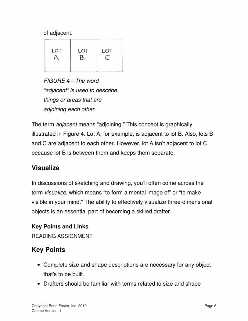
of adjacent.
FIGURE 4—The word
“adjacent” is used to describe
things or areas that are
adjoining each other.
The term adjacent means “adjoining.” This concept is graphically
illustrated in Figure 4. Lot A, for example, is adjacent to lot B. Also, lots B
and C are adjacent to each other. However, lot A isn’t adjacent to lot C
because lot B is between them and keeps them separate.
Visualize
In discussions of sketching and drawing, you’ll often come across the
term visualize, which means “to form a mental image of” or “to make
visible in your mind.” The ability to effectively visualize three-dimensional
objects is an essential part of becoming a skilled drafter.
Key Points and Links
READING ASSIGNMENT
Key Points
Complete size and shape descriptions are necessary for any object
that's to be built.
Drafters should be familiar with terms related to size and shape
Page 6Copyright Penn Foster, Inc. 2019 Course Version: 1
description, including pictorial drawing, perpendicular, adjacent, two-
and three-dimensional, and visualize.
Discover More: Sketching Terminologies
Fill in the blank.
1. If any figure pair with two or three dimensions is drawn next to each
other, they would be considered _______ figures.
2. When you attempt to use sketches to show a complete view of a
machine, you’re essentially trying to describe the machine’s _______
graphically.
3. A drafter’s skill depends to a large extent on the ability to _______—
to imagine what an object would look like.
4. In a three-dimensional sketch, _______ is revealed along with an
object’s height and width.
5. If two lines meet to form a right angle, they would be considered
_______ lines.
6. _______ drawings show how an object would appear from one
perspective—as though the object were in a photograph.
7. The process of communicating all the dimensions of a product’s
several components is called the product’s _______ description.
Discover More Answer Key:
Discover More: Sketching Terminologies
1. adjacent
2. shape
Page 7Copyright Penn Foster, Inc. 2019 Course Version: 1

3. visualize
4. depth
5. perpendicular
6. Pictorial
7. size
2.2 Explain the process of making an orthographicprojection for an objectMaking an Orthographic Projection
READING ASSIGNMENT
An image of a pictorial drawing
showing what an object will look
like without a complete
description.
FIGURE 5—This pictorial
drawing shows what the object
would really look like, but it
Page 8Copyright Penn Foster, Inc. 2019 Course Version: 1
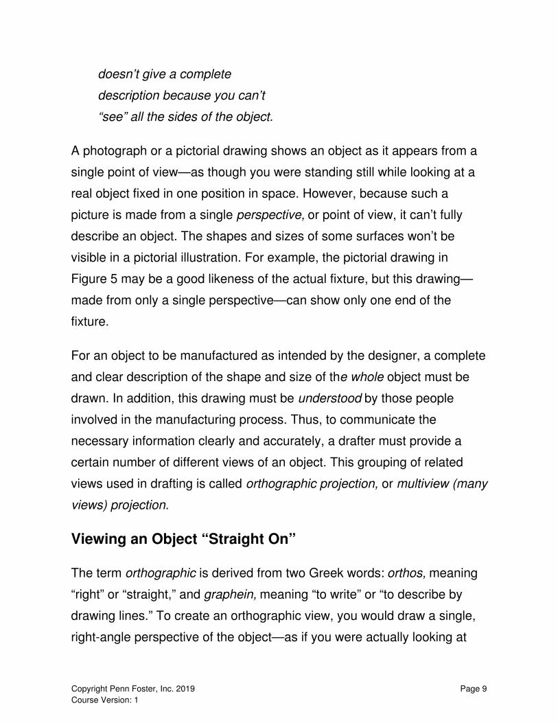
doesn’t give a complete
description because you can’t
“see” all the sides of the object.
A photograph or a pictorial drawing shows an object as it appears from a
single point of view—as though you were standing still while looking at a
real object fixed in one position in space. However, because such a
picture is made from a single perspective, or point of view, it can’t fully
describe an object. The shapes and sizes of some surfaces won’t be
visible in a pictorial illustration. For example, the pictorial drawing in
Figure 5 may be a good likeness of the actual fixture, but this drawing—
made from only a single perspective—can show only one end of the
fixture.
For an object to be manufactured as intended by the designer, a complete
and clear description of the shape and size of the whole object must be
drawn. In addition, this drawing must be understood by those people
involved in the manufacturing process. Thus, to communicate the
necessary information clearly and accurately, a drafter must provide a
certain number of different views of an object. This grouping of related
views used in drafting is called orthographic projection, or multiview (many
views) projection.
Viewing an Object “Straight On”
The term orthographic is derived from two Greek words: orthos, meaning
“right” or “straight,” and graphein, meaning “to write” or “to describe by
drawing lines.” To create an orthographic view, you would draw a single,
right-angle perspective of the object—as if you were actually looking at
Page 9Copyright Penn Foster, Inc. 2019 Course Version: 1

one side of the object straight on. Figure 6 shows an example of how an
orthographic view may be created. The important thing to remember is
that, in an orthographic view, the surface being viewed is perpendicular
(at a right angle) to the viewer’s line of sight. If you look straight toward
the face of an object, you’ll get a true view of the shape and size of that
one surface.
An image with two sketches showing an orthographic view.
FIGURE 6—An orthographic view is taken "straight on," as though you
were positioned at a right angle to the object's surface.
Combining Views to Make an Orthographic Projection
When making an orthographic view of an object, it’s almost as though you
were projecting an outline of a single surface straight onto your drawing
pad. In drafting, however, the goal of the orthographic projection is to
project a number of the object’s surfaces to create several single views.
Each view would be perpendicular to the other orthographic views.
For example, look at Figure 7. In Figure 7A, the object is being “turned”
Page 10Copyright Penn Foster, Inc. 2019 Course Version: 1

90° from its front side so that the object’s right side could be “viewed”
straight on. The right side of the object is perpendicular to the object’s
front side. In Figure 7B, the object is being turned so that the top side can
be viewed straight on. The top is perpendicular both to the object’s front
and to its right side. Figure 7C shows how these three separate views—
top, front, and right side—are combined with a pictorial view to give a
somewhat complete description of the object’s shape. The front, top, and
right-side views are called the three regular views because they’re the
ones most frequently used. Later, you’ll learn other views used in
orthographic projection.
An image with three sets of sketches showing an orthographic projection,
which combines several perspectives to give a detailed description of an
object.
Page 11Copyright Penn Foster, Inc. 2019 Course Version: 1
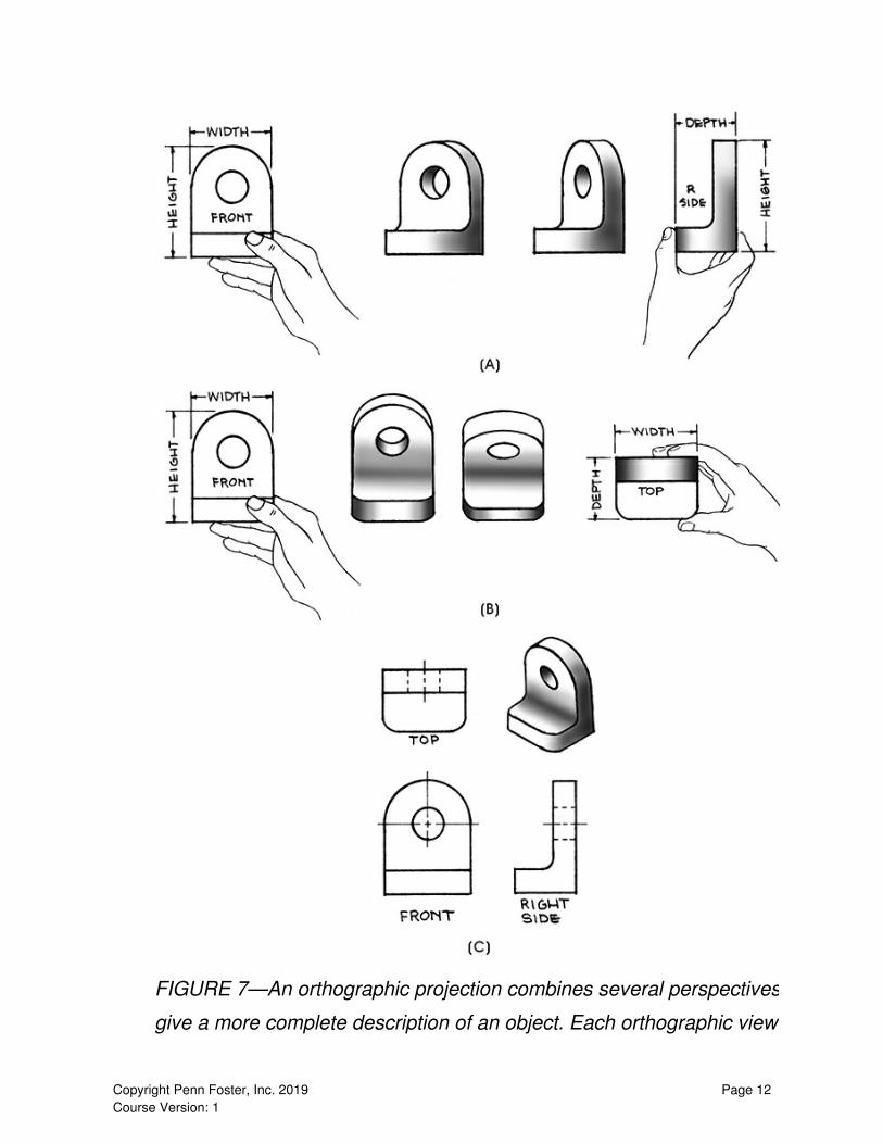
FIGURE 7—An orthographic projection combines several perspectives to
give a more complete description of an object. Each orthographic view is
Page 12Copyright Penn Foster, Inc. 2019 Course Version: 1

perpendicular to the others.
Selecting the Three Regular Views to Make a ShapeDescription
An image with two illustrations
showing a pictorial view and the
top view of a book.
FIGURE 8—The drafter has
selected the front cover of the
book as the object’s top view.
This selection is logical
because the front cover is the
side of the object with the
largest surface area. In drafting,
such a surface would typically
be chosen as the top view.
The drafter decides which side of an object will be the front view for a
sketch. Usually, the largest surface of the object is selected to be the top
view. A side perpendicular to the top view—perhaps the one with the most
detail—would be selected as the front view. As part of the three regular
views, the side perpendicular to and to the right of the front view would be
Page 13Copyright Penn Foster, Inc. 2019 Course Version: 1

called the right-side view.
For example, consider the pictorial drawing of the book shown in Figure
8A. Normally, we would think of the front of a book as the book’s front
cover. However, what we would normally call the front of the book isn’t
necessarily the front view when we’re trying to describe the book’s shape.
As shown in Figure 8B, the drafter decided to let the front cover of the
book serve as the top view.
Now that the top view has been established, the drafter can select an
appropriate front view for describing the size of the book. The front view
would be a side at a right angle to the top view. The spine of this book
offers the most detail out of all the other choices; therefore, in this
instance, the drafter selected the spine as the front view. Thus, the right-
side view in this projection is the side to the right of the spine. Figure 9
shows these three regular views together with a pictorial drawing of the
book. Remember, you’re not naming the sides of the book in an attempt to
describe how it would sit on a shelf. The side that would rest on the
bookshelf might be called the bottom edge of the book. However, because
you’re trying to create an orthographic projection, you’ll name that edge
the right-side view.
An image with four illustrations showing the top, the front, and the right
side view of a book along with a pictorial view with the top, front, and right
side marked.
Page 14Copyright Penn Foster, Inc. 2019 Course Version: 1

FIGURE 9—Here are shown the three regular views appropriate for an
orthographic projection of a book. Whenever you lay out the three regular
views of an object, try to choose those three surfaces that will show the
most detail; that is, choose the views that will give the best shape
description.
In Figure 9, the three regular views of the book have given the object its
shape description. The solid black continuous lines, often called visible
lines, form the outline of the object. The visible lines correspond to the
edges you would see when you look at that surface of the object. The
short dashed lines correspond to edges that are not visible when you view
the surface. These dashed lines are called hidden lines, or invisible lines.
Using the Orthographic Projection to Make a SizeDescription
The Three Principal Dimensions
Page 15Copyright Penn Foster, Inc. 2019 Course Version: 1

A finished orthographic projection can be used to provide a size
description as well as a shape description. As shown in Figure 10, the
completed drawing can include dimensions used to identify sizes in each
view. If you were making an actual layout of the book, the words height,
width, and depth would be replaced with actual measurements made of
the object’s top, front, and right side.
An image with four illustrations showing the top, the front, and the right
side view of a book along with a pictorial view with the height, width, and
depth marked.
FIGURE 10—Here are the top, front, and right-side views of a book
together with a pictorial view. Note that dimensions have been added to
these three regular views. On a finished drawing, the dimension labels
would be replaced with corresponding measurements made of the actual
book.
Page 16Copyright Penn Foster, Inc. 2019 Course Version: 1
The three principal dimensions shown in Figure 10 are the book’s height,
width, and depth. Generally, the terms length and thickness aren’t used in
drafting because they won’t apply as dimensions in all cases. One such
case where thickness would be used, however, is for describing sheet
metal parts. With sheet metal, what you would normally call the height
would be the metal’s thickness dimension.
Note that the front view of the book shows the height and width of the
object, but not the depth. In fact, any single view of a three-dimensional
object shows only two dimensions; the third dimension is found in an
adjacent view. The measurements corresponding to the height, width, and
depth dimensions form the size description of an object.
Characteristics of Height, Width, and Depth
The height dimension. The height of an object is its size measured
straight up and down. As an example, consider a dresser or a chest of
drawers that you may have in your bedroom. The height of the dresser is
measured from the floor to the top of the dresser. This measurement is of
a vertical distance. Note that the height of the book in Figure 10 is shown
in both the front and right-side views. Essentially, an object’s height is its
size from top to bottom.
The width dimension. The width of an object is its size measured
straight across the front, from the left side to the right side. The width of a
dresser, for example, is measured across its front, from the left side to the
right side. Note that the width of the book in Figure 10 is shown in both the
top and front views. Basically, an object’s width is measured across the
front of the object.
Page 17Copyright Penn Foster, Inc. 2019 Course Version: 1
The depth dimension. The depth of an object is its size measured from
front to back. The depth of a dresser, for example, is the distance from the
front of the dresser to the back of the dresser. Note that the depth of the
book in Figure 10 is shown in both the top and right-side views. In
essence, depth is the size of an object from its front to its back.
Key Points and Links
READING ASSIGNMENT
Key Points
An orthographic projection is a multi-viewed illustration of an object.
Three regular views and three principal dimensions combine for a
shape and size description of an object.
Height, width, and depth are important measurement characteristics
of an object.
Discover More: Fundamentals of Orthographic Projections
Fill in the blank.
1. A/An ______ drawing is simply an attempt to show how an object
would appear as though it were in a photograph.
2. A/An _______ is often used to provide a size and shape description
of an object.
3. The three regular views in an orthographic projection are top, front,
and ______.
4. Another name for orthographic projection is ______ projection.
5. Orthographic views are at ______ angles to each other.
Page 18Copyright Penn Foster, Inc. 2019 Course Version: 1

6. The three principal _______ are height, width, and depth.
7. Height and width are shown in an object’s ______ view.
Identify the principal dimensions—the pan’s height, width, and depth
—where they would be shown in each orthographic view.
An illustration of the top view, pictorial view, front view and right
side view of a pan.
Discover More Answer Key:
Discover More: Fundamentals of Orthographic Projections
1. pictorial
2. orthographic projection
3. right-side
4. multiview
5. right
6. dimensions
7. front
Page 19Copyright Penn Foster, Inc. 2019 Course Version: 1

An image with answer to problem 3 containing four sketches of
different views of a pan with the height and width marked.
2.3 Describe how the surfaces are represented in variousorthographic viewsDistinguishing the Different Surfaces of an Object Shown in Different
Views
READING ASSIGNMENT
When examining an orthographic projection, you’ll need to recognize what
surfaces are being presented in each view. The pictorial drawing in Figure
11A shows how surface 1 through surface 5 would appear if you were
viewing the real object. Look at how surface 1 appears in the pictorial
drawing, and compare it with how it’s shown in the top, front, and right-
side views featured in Figure 11B. Note that only a single edge of surface
Page 20Copyright Penn Foster, Inc. 2019 Course Version: 1

1 is visible in the top view. In the front view, however, surface 1 is shown
in its true shape. In the right-side view, an edge of surface 1 is once again
all that’s visible.
An image with two sets of sketches showing one pictorial drawing and
three sets of regular orthographic views of an object with all the surfaces
represented.
Page 21Copyright Penn Foster, Inc. 2019 Course Version: 1

FIGURE 11—To "read" an orthographic projection, you need to recognize
which surfaces and edges of the object correspond to the areas and lines
Page 22Copyright Penn Foster, Inc. 2019 Course Version: 1

shown in each orthographic view.
Examine how all the surfaces are represented in each view of the object
featured in Figure 11. As you practice “reading” the various orthographic
views, you’ll learn to visualize the three-dimensional shape of an object
even when you don’t have a pictorial view. In addition, your practice will
help you in laying out an orthographic projection when all you have is a
pictorial view. Therefore, whenever you study an object, practice
visualizing how the three views would be presented.
PRACTICE PLATES
Examine the sketches contained in the linked practice plates.
A plate is a completed drawing on a single sheet of paper or vellum. Any
plates that you create during your training you should place in a personal
file of drawings. Someday this file may help you obtain employment as a
drafter. Practice Plate 1A contains four sets of drawings. Each set
consists of a pictorial drawing and three corresponding orthographic
views. Practice Plate 2A contains two sets of drawings. Note that, in both
practice plates, the surfaces visible on all the pictorial drawings have been
lettered.
For each pictorial drawing, identify the surfaces and surface edges shown
on the corresponding orthographic views by printing the appropriate
letters in the circles. The first set of orthographic views in Practice Plate
1A has been done for you. Once you’ve finished lettering the surfaces and
edges in each regular view, go through both practice plates to check for
errors. This proofing is a good habit that you should adopt as a standard
Page 23Copyright Penn Foster, Inc. 2019 Course Version: 1
procedure in your studies as well as on the job.
Once you've completed Practice Plate 1A and 2A, check your answers
with Practice Plate 2A and 2B.
Practice Plate 1A–B (lessons.pennfoster.com/pdf/Practice_Plates_1
A-B.pdf)
Practice Plate 2A–B (lessons.pennfoster.com/pdf/Practice_Plates_2
A-B.pdf)
Key Points and Links
READING ASSIGNMENT
Key Points
Drafters should be able to recognize which surfaces are being
presented in each view of an orthographic projection.
The ability to visualize allows a drafter to “see” an object without a
physical representation.
Lesson 2 Review
Self-Check
1. The depth dimension, as shown in an object’s top view, is usually
measured in what direction?
a. From right to left
Page 24Copyright Penn Foster, Inc. 2019 Course Version: 1

b. From corner to corner
c. From the center out
d. From front to back
2. As shown in the top and front views of an object, the width dimension is
usually measured in what direction?
a. From left to right
b. From back to front
c. From corner to corner
d. From bottom to top
3. As shown in the side view of an object, the depth dimension is usually
measured in what direction?
a. From left to right
b. From top to bottom
c. From corner to corner
d. From the center out
4. The front view of an object shows which two dimensions?
a. Height and width
b. Depth and width
c. Height and thickness
d. Height and depth
5. The top view of an object shows which dimensions?
a. Depth and width
b. Height and thickness
c. Height and depth
d. Height and width
6. A technician requiring many views of a product, in full detail, is likely to
receive a/an
Page 25Copyright Penn Foster, Inc. 2019 Course Version: 1

a. size description.
b. object description.
c. full-view description.
d. shape description.
7. A builder requiring the complete dimensions of an object is likely to
receive a/an
a. size description.
b. shape description.
c. object description.
d. full-view description.
8. A pictorial drawing is most likely to be _______-dimensional.
a. one
b. three
c. two
d. four
9. Two lines that are perpendicular to one another meet at which angle?
a. 15 degrees
b. 60 degrees
c. 90 degrees
d. 180 degrees
10. In a diagram, three squares of equal size are placed in a row next to
each other and labeled A, B, and C. If square A is directly to the left of
square B and square C is directly to the right of square B, how would you
describe the location of square B in relation to square A?
a. Perpendicular
b. Horizontal
c. Adjacent
Page 26Copyright Penn Foster, Inc. 2019 Course Version: 1

d. Supplementary
11. Being able to _______ will help a drafter imagine an object without a
physical representation.
a. visualize
b. sketch
c. project
d. describe
12. How many perspectives are available with a pictorial drawing?
a. 2
b. 3
c. 1
d. 4
13. At which angle is the surface of an object being observed in an
orthographic view?
a. Right
b. Acute
c. Obtuse
d. Straight
14. Which surfaces constitute the "three regular views" of an orthographic
projection?
a. Front, top, and right-side
b. Top, bottom, and right-side
c. Top, right-side, and left-side
d. Front, top, and left-side
15. Which part of an object is selected for the "top view"?
a. The smoothest surface of the object
b. The surface of the object that faces up
Page 27Copyright Penn Foster, Inc. 2019 Course Version: 1

c. The surface of the object that faces down
d. The largest surface of the object
16. Where is the "right-side view" located in relation to the "front view"?
a. Perpendicular and to the left
b. Parallel and to the right
c. Perpendicular and to the right
d. Parallel and to the left
17. In which situation would a drafter encounter the term "thickness"?
a. When describing the "width" dimension of sheet metal
b. When describing the "length" dimension of sheet metal
c. Never
d. When describing the "height" dimension of sheet metal
18. Orthographic views must be _______ to create an accurate
orthographic projection.
a. combined
b. symmetrical
c. identical
d. presented individually
19. When sketching an object, which features identify its outline?
a. Dotted lines
b. Light shading
c. Solid black lines
d. Arrows
20. When viewing a surface of an object, some edges won't be visible.
How are these features identified?
a. Jagged lines
b. Dashed lines
Page 28Copyright Penn Foster, Inc. 2019 Course Version: 1

c. Points
d. Labels
21. You're given an object that measures 11 inches up and down, 4.5
inches straight across the front, and 7.25 inches front to back. What's the
object's height?
a. 4.5 inches
b. 7.25 inches
c. 11 inches
d. 11.75 inches
22. You're given an object that measures 2 inches up and down, 18
inches straight across the front, and 2.5 inches front to back. What is the
object's width?
a. 18 inches
b. 2 inches
c. 2.5 inches
d. 20.5 inches
23. You're given an object that measures 1.75 inches up and down, 3
inches straight across the front, and 3.75 inches front to back. What is the
object's depth?
a. 1.75 inches
b. 3.75 inches
c. 3 inches
d. 5 inches
24. How many dimensions are visible in any single view of a three-
dimensional object?
a. Only two dimensions
b. Only one dimension
Page 29Copyright Penn Foster, Inc. 2019 Course Version: 1

c. All three dimensions
d. No dimensions
25. What should a drafter be able to recognize when viewing an
orthographic projection?
a. Materials
b. The cost to construct the object
c. The time to construct the object
d. Surfaces
Self-Check Answer Key
1. From front to back
Explanation: The depth dimension of an object is its size measured
from front to back. The depth dimension of an object is the distance
from the front of the object to the back of the object.
Reference: Section 2.2
2. From left to right
Explanation: The width of an object is its size measured straight
across the front, from the left side to the right side. The width of an
object is measured across its front, from the left side to the right side.
Reference: Section 2.2
3. From left to right
Explanation: The side view of an object is its size measured straight
across the front, from the left side to the right side.
Reference: Section 2.2
Page 30Copyright Penn Foster, Inc. 2019 Course Version: 1
4. Height and width
Explanation: The front view of an object shows the height and width
of the object, but not the depth.
Reference: Section 2.2
5. Depth and width
Explanation: The top view of an object shows the depth and width of
the object, but not the height.
Reference: Section 2.2
6. shape description.
Explanation: A shape description shows a complete and detailed
view of an object from different sides.
Reference: Section 2.1
7. size description.
Explanation: A size description shows the various measurements and
dimensions of an object.
Reference: Section 2.1
8. three
Explanation: Pictorial drawings show how an object would appear in
"real life," often as if photographed, and include the object's height,
width, and depth.
Reference: Section 2.1
9. 90 degrees
Page 31Copyright Penn Foster, Inc. 2019 Course Version: 1

Explanation: Perpendicular means "at a right angle to" and a right
angle equals 90 degrees.
Reference: Section 2.1
10. Adjacent
Explanation: The word adjacent is used to describe things or areas
that are lying near to, close to, or adjoining one another.
Reference: Section 2.1
11. visualize
Explanation: Visualizing is forming a mental image of something.
Reference: Section 2.1
12. 1
Explanation: A pictorial drawing offers only a single perspective of an
object.
Reference: Section 2.2
13. Right
Explanation: In an orthographic view, the surface being viewed is
perpendicular (at a right angle) to the viewer's line of sight.
Reference: Section 2.2
14. Front, top, and right-side
Explanation: The front, top, and right-side views are called the "three
regular views" because they're the ones most frequently used.
Reference: Section 2.2
Page 32Copyright Penn Foster, Inc. 2019 Course Version: 1
15. The largest surface of the object
Explanation: Usually, the largest surface of an object is selected to
be the "top view."
Reference: Section 2.2
16. Perpendicular and to the right
Explanation: As part of the three regular views, the side
perpendicular to and to the right of the front view would be called the
right-side view.
Reference: Section 2.2
17. When describing the "height" dimension of sheet metal
Explanation: While the term "thickness" (along with "length") isn't
used in drafting because it doesn't apply as a dimension in all cases,
it's used to describe the height of sheet metal.
Reference: Section 2.2
18. combined
Explanation: The goal of the orthographic projection is to project a
number of the object's surfaces to create several single views.
Reference: Section 2.2
19. Solid black lines
Explanation: The outline of an object is identified with solid black,
continuous lines.
Reference: Section 2.2
Page 33Copyright Penn Foster, Inc. 2019 Course Version: 1

20. Dashed lines
Explanation: Dashed lines are used to identify edges that aren't
visible when viewing a particular surface of an object.
Reference: Section 2.2
21. 11 inches
Explanation: An object's height is measured straight up and down, its
width straight across the front (from left to right), and its depth front to
back.
Reference: Section 2.2
22. 18 inches
Explanation: An object's height is measured straight up and down, its
width straight across the front (from left to right), and its depth front to
back.
Reference: Section 2.2
23. 3.75 inches
Explanation: An object's height is measured straight up and down, its
width straight across the front (from left to right), and its depth front to
back.
Reference: Section 2.2
24. Only two dimensions
Explanation: Any single view of a three-dimensional object will show
only two dimensions; the third dimension will be found in an adjacent
Page 34Copyright Penn Foster, Inc. 2019 Course Version: 1

view.
Reference: Section 2.2
25. Surfaces
Explanation: When examining an orthographic projection, a drafter
needs to recognize what surfaces are being presented in each view.
Reference: Section 2.3
Flash Cards
1. Term: Shape Description
Definition: A complete view of an object showing different sides
2. Term: Size Description
Definition: The process of communicating all the dimensions of the
various components of an object
3. Term: Pictorial Drawing
Definition: An illustration that shows how an object would appear in "real
life"—as though it had been photographed
4. Term: Perpendicular
Definition: At a right angle to
5. Term: Adjacent
Definition: Lying near to, close to, or adjoining
6. Term: Two-Dimensional Drawing
Page 35Copyright Penn Foster, Inc. 2019 Course Version: 1
Definition: An illustration of an object showing its height and width
7. Term: Three-Dimensional Drawing
Definition: An illustration of an object showing its height, width, and depth
8. Term: Visualize
Definition: To form a mental image of
9. Term: Perspective
Definition: Point of view
10. Term: Orthographic Projection
Definition: A multiviewed illustration
11. Term: Visible Lines
Definition: Solid black continuous lines that form the outline of an object
12. Term: Hidden Lines
Definition: Dashed lines corresponding to edges that aren't visible when
viewing an object's surface
13. Term: Height
Definition: An object's size measured straight up and down
14. Term: Width
Definition: An object's measurement straight across the front, from left to
right
Page 36Copyright Penn Foster, Inc. 2019 Course Version: 1

15. Term: Depth
Definition: An object's measurement from front to back
Page 37Copyright Penn Foster, Inc. 2019 Course Version: 1