Embed Size (px)
Citation preview

Sivoia® QS
wiring and programmingguide

Sivoia® QS Wiring and Programming Guide
Sivoia QS Drives are available for control of Draperies, Roller Shades and Tensioned Shades. Sivoia QS Shades and Draperies can be controlled as part of a QS System, incorporating GRAFIK Eye QS lighting controls, or as a Shades/Draperies only System, without lighting controls.
Sivoia QS Drives and Keypads are powered from a 24 V--- power supply. All drives, power supplies, keypads and other control devices are linked together with the same four wire communication link. This link provides 24 V--- to all components.
The Shades/Draperies can also be operated via an infrared Hand-Held Remote Control. These can be used in either a GRAFIK Eye QS Integrated System or Sivoia QS Standalone System. The IR remotes can move the Shade or Drapery to the open and close limit. They also provide the additional functions of storing and recalling a favorite preset, and setting open and close limits remotely.
Page 1
Sivoia® QS Wiring and Programming Guide

Page 2
Sivoia® QS Wiring and Programming Guide
Table of contents Page
WiringQS link power supplySmart panel - one shade per outputSmart panel - two shades per outputSmart panel - three shades per outputGRAFIK Eye QS integrationWire length chart
Setting limitsFrom the driveFrom a keypad
Verifying communicationFrom the driveFrom the smart panel
ProgrammingAssigning shades/draperies to keypadsStoring presets from a keypadIndividual level adjust
Restoring defaultsDriveKeypad
TroubleshootingTroubleshooting Chart
345678
912
10 10
111314
1516
17
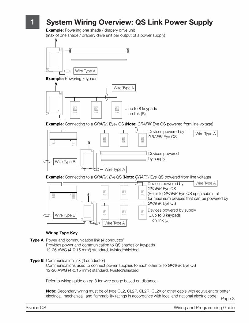
1 System Wiring Overview: QS Link Power SupplyExample: Powering one shade / drapery drive unit (max of one shade / drapery drive unit per output of a power supply)
Example: Powering keypads
Example: Connecting to a GRAFIK Eye® QS (Note: GRAFIK Eye QS powered from line voltage)
Example: Connecting to a GRAFIK Eye QS (Note: GRAFIK Eye QS powered from line voltage)
Communication link (3 conductor)Communications used to connect power supplies to each other or to GRAFIK Eye QS12-26 AWG (4-0.15 mm²) standard, twisted/shielded
Refer to wiring guide on pg 8 for wire gauge based on distance.
Note: Secondary wiring must be of type CL2, CL2P, CL2R, CL2X or other cable with equivalent or better electrical, mechanical, and flammability ratings in accordance with local and national electric code.
Wiring Type Key
Power and communication link (4 conductor)Provides power and communication to QS shades or keypads12-26 AWG (4-0.15 mm²) standard, twisted/shielded
Close
Open
Preset
Close
Open
Preset
Close
Open
Preset
Close
Open
Preset
Close
Open
Preset
Close
Open
Preset
...up to 8 keypads on link (B)
Close
Open
Preset
Close
Open
Preset
Close
Open
Preset
Close
Open
Preset
Close
Open
Preset
Close
Open
Preset
...up to 8 keypads on link (B)
Devices powered by GRAFIK Eye QS
Devices powered by supply
Devices powered by
Devices powered by supply
GRAFIK Eye QS(Refer to GRAFIK Eye QS spec submittalfor maximum devices that can be powered by GRAFIK Eye QS
Wire Type B
Wire Type A
Wire Type A
Wire Type A
Wire Type B
Wire Type A
Wire Type A
Wire Type A
Type A
Type B
Page 3
Sivoia® QS Wiring and Programming Guide

Sivoia QS System Wiring:Smart Panel power supply, single shade per output
2
Wiring Type Key
Type A Communications Link: 4 Conductor (twisted and shielded), listed for application Refer to wiring guide on pg. 8 for wire gauge based on distance Maximum comm. link: – Up to 2000 ft (600 m) connecting
all QSPS-P1-10-60 panels
100 Devicesper link max.100 Zones
Wire Type A
QSPS-P1-10-60 10 Output Smart Panel power supply
Wire Type A
QSPS-P1-10-60 10 Output Smart Panel power supply
Wire Type A
120 V~ 60 Hz
120 V~ 60 Hz
To other QS Controls
seeTouch® QS keypads
Wire Type A
Sivoia QS roller shade
Sivoia QS skylight shade
Sivoia QS drapery track
Page 4
Sivoia® QS Wiring and Programming Guide
Note: Secondary wiring must be of type CL2, CL2P, CL2R, CL2X or other cable with equivalent or better electrical, mechanical, and flammability ratings in accordance with local and national electric code.

Page 5
Sivoia® QS Wiring and Programming Guide
Sivoia QS System Wiring:Smart Panel power supply, two shades per output*
3
100 Devicesper link max.100 Zones
QSPS-P1-10-60 10 Output Smart Panel power supply
Wire Type A
QSPS-P1-10-60 10 Output Smart Panel power supply
To other QS Controls
seeTouch® QS keypads
Wire Type A
Wire Type A
120 V~60 Hz
120 V~60 Hz
Wire Type A
Sivoia QS roller 64TM or roller 100TM*
*Number of shades per output will vary based on roller type and size of roller shade. Refer to page 8 for wiring guidelines
Wiring Type Key
Type A Communications Link: 4 Conductor (twisted and shielded), listed for application Refer to wiring guide on pg. 8 for wire gauge based on distance Maximum comm. link: – Up to 2000 ft (600 m)
connecting all QSPS-P1-10-60 panels
Note: Secondary wiring must be of type CL2, CL2P, CL2R, CL2X or other cable with equivalent or better electrical, mechanical, and flammability ratings in accordance with local and national electric code.

Sivoia QS System Wiring:Smart Panel power supply, three shades per output*
4
100 Devicesper link max.100 Zones
QSPS-P1-10-60 10 Output Smart Panel power supply
Wire Type A
QSPS-P1-10-60 10 Output Smart Panel power supply
To other QS Controls
seeTouch® QS keypads
Wire Type A
Wire Type A
120 V~60 Hz
120 V~60 Hz
Wire Type A
Sivoia QS roller 64TM*
*Number of shades per output will vary based on roller type and size of roller shade. Refer to page 8 for wiring guidelines
Wiring Type Key
Type A Communications Link: 4 Conductor (twisted and shielded), listed for application Refer to wiring guide on pg. 8 for wire gauge based on distance Maximum comm. link: – Up to 2000 ft (600 m)
connecting all QSPS-P1-10-60 panels
Page 6
Sivoia® QS Wiring and Programming Guide
Note: Secondary wiring must be of type CL2, CL2P, CL2R, CL2X or other cable with equivalent or better electrical, mechanical, and flammability ratings in accordance with local and national electric code.

Page 7
Sivoia® QS Wiring and Programming Guide
Sivoia QS with GRAFIK Eye® QS System Wiring: Smart Panel power supply, single shade per output*
5
100 Devicesper link max.100 Zones
Wire Type A
QSPS-P1-10-60 10 Output Smart Panel power supply
Wire Type A
QSPS-P1-10-60 10 Output Smart Panel power supply
Wire Type A120 V~60 Hz
120 V~60 Hz
To other QS Controls
seeTouch® QS keypads
Wire Type A
Sivoia QS roller shade
GRAFIK Eye® QS
Wiring Type Key
Type A Communications Link: 4 Conductor (twisted and shielded), listed for application Refer to wiring guide on pg. 8 for wire gauge based on distance Maximum comm. link: – Up to 2000 ft (600 m)
connecting all QSPS-P1-10-60 panels
RS232 Interface
Sivoia QS skylight shade
Sivoia QS drapery track
Note: Secondary wiring must be of type CL2, CL2P, CL2R, CL2X or other cable with equivalent or better electrical, mechanical, and flammability ratings in accordance with local and national electric code.

Page 8
Sivoia® QS Wiring and Programming Guide
6 Wire Length Chart
Maximum devices per one output Maximum distance per one output based on wire guage
Shades + Controls12 AWG4 mm²
QSH-CBL-L-500QSH-CBLP-L-500
16 AWG1.5 mm²
QSH-CBL-M-500QSH-CBLP-
M-500
18 AWG1 mm²
GRX-CBL-346S-500
NoneUp to 8
seeTouch QS keypads1200 ft (350 m) 500 ft (150 m) 300 ft (90 m)
1 Sivoia QS shade/drapery drive unitUp to 1
seeTouch QS keypad500 ft (150 m) 200 ft (60 m) 125 ft (35 m)
2 Sivoia QS roller 64, ≤ 30 sq ft (2.75 sq m) each
None 200 ft (60 m) 75 ft (20 m) 50 ft (15 m)
3 Sivoia QS roller 64, ≤ 20 sq ft (1.80 sq m) each
None 200 ft (60 m) 75 ft (20 m) 50 ft (15 m)
2 Sivoia QS roller 100, ≤ 50 sq ft (4.6 sq m) each
None 200 ft (60 m) 75 ft (20 m) 50 ft (15 m)
Maximum devices from one QS Link power supply Total wire length based on wire gauge
Shades + Controls12 AWG4 mm²
QSH-CBL-L-500QSH-CBLP-L-500
16 AWG1.5 mm²
QSH-CBL-M-500QSH-CBLP-
M-500
18 AWG1 mm²
GRX-CBL-346S-500
NoneUp to 8
seeTouch QS keypads1200 ft (350 m) 500 ft (150 m) 300 ft (90 m)
1 Sivoia QS shade*/drapery drive unitUp to 1
seeTouch QS keypad250 ft (75 m) 100 ft (30 m) 50 ft (15 m)
QS Smart Panel Power Supply Wiring GuideLink Rules • Maximum of 100 devices (such as GRAFIK Eye® QS, seeTouch® QS keypad, smart panel power • supply, or Sivoia® QS shade/drapery drive unit) • Maximum of 100 zones (such as Sivoia QS shade/drapery drive unit, or a lighting zone on a • GRAFIK Eye QS) • Maximum 2000 ft. (600 m) of cable connecting all smart panel power supplies • Maximum 2000 ft. (600 m) of cable to devices wired from each smart panel power supply • Only use cable with at least one twisted/shielded pair for communicationsUse this chart to determine the number of shades and/or controls that can be run from one output on the Sivoia QS Smart Panel power supply, depending on the size of the shade. Then, verify the maximum cable length for the output configuration, based on the wire gauge that will be used.
QS Link Power Supply Wiring GuideLink Rules • Only use cable with at least one twisted/shielded pair for communications • Total length of power supply link (A) wire plus device link (B) wire in entire system must be less than 2000 ft. (600 m)Use this chart to determine the number of shades and/or controls that can be run from one QS Link power supply. Then, verify the maximum cable length for the output configuration, based on the wire gauge that will be used.
* 2 seeTouch QS keypads may be exchanged for 1 control interface (QSE-CI-NWK-E)
Note: Secondary wiring must be of type CL2, CL2P, CL2R, CL2X or other cable with equivalent or better electrical, mechanical, and flammability ratings in accordance with local and national electric code.

7 Setting Limits From the Drive
The open and close limits define the travel range of the shade or drapery. Limits can be set at the Drive, or from a keypad or an IR Remote previously assigned to that Drive. It is recom-mended that limits be set initially at the Drive.
Setting Open Limit
Tap Open Limit button. Green LED will turn on.
Move the Shade or Drapery to desired Open Limit by pressing arrow buttons.
Press and hold the Open Limitbutton until the Green LED flashes. Open Limit is stored.
7.1
7.2
7.3
Tap the Close Limit button. The Green LED will turn on.
Move the Shade or Drapery to desired Close Limit by pressing arrow buttons.
Press and hold the Close Limit button until the Green LED flashes. Close Limit is stored.
7.4
7.5
7.6
Setting Close Limit
Page 9
Sivoia® QS Wiring and Programming Guide
T
HH
H
T
HH
H
or
or

Page 10
Sivoia® QS Wiring and Programming Guide
8 Verify Communication
Press and hold Close ( ) for 5 seconds,
Press and hold Close ( ) to exit Link Diagnostics Mode.
8.1
8.3
Tap Open, hold Open 5 seconds., tap Open, hold Open 5 seconds.- All shades/draperies will wiggle*
8.4
Press and hold Open 5 sec. to exit Link Diagnostics mode8.5
(*) If any shade/drapery is not wiggling, check the wiring
From a Drive:
Tap CCW ( ) to enter Link Diagnostics mode -All shades/draperies will wiggle*
8.2
From the Sivoia QS Smart Panel:
Sivoia QS
120 V~60 Hz
H
T
H
T, H, T, H
H

Page 11
Sivoia® QS Wiring and Programming Guide
9 Assigning Shades/Draperies to Keypads
Press and hold Open and Close simultaneously for 5 seconds-Shades/draperies that are assigned will move to close (down)-Shades/draperies that are unassigned will move to open (up)
Tapping Open jogs “forward, Close jogs “backward” through the shades/draperies
9.1
9.2
Tap the Lower ( ) to assign or Raise ( ) to unassign a shade/drapery
9.3
Press and hold Open and Close simultaneously for 5 seconds to exit
9.4
H
T
T
Hand
Tor
T
or
H
Hand

Page 12
Sivoia® QS Wiring and Programming Guide
10 Setting Limits From a Keypad
Press and hold Open and Raise ( ) simultaneously for 5 seconds
Tapping Open jogs “forward, Close jogs “backward” through the assigned shades/draperies
10.1
10.2
Use Raise ( ) and Lower ( ) to adjust shade/drapery position10.3
Press and hold Open for 5 seconds to store the open limit or Close for 5 seconds to store the close limit
10.4
Press and hold Open and Raise ( ) simultaneously for 5 seconds to exit
10.5
T
H
and
Tor
H
Hor
H
or
H
H
andH
H

Page 13
Sivoia® QS Wiring and Programming Guide
11 Storing Presets from a Keypad
Adjust the shade/drapery to the desired position using raise or lower buttons.
11.1
Store the current position of the shade/drapery by pressing and holding the desired Preset button for 5 seconds
11.2 H ororH
H
T T
or

Page 14
Sivoia® QS Wiring and Programming Guide
12 Individual Level Adjust
Press and hold Open and Close simultaneously for 5 seconds-Shades/draperies that are assigned will move to close (down)-Shades/draperies that are unassigned will move to open (up)
Tapping Open jogs “forward, Close jogs “backward” through the assigned shades/draperies
12.1
12.2
Use Raise ( ) and Lower ( ) to adjust shade/drapery position12.3
Repeat steps 12.2 & 12.3 to adjust additional shades/draperies12.4
Store the current position of the shades/draperies by pressing and holding the desired Preset button for 5 seconds
12.5
Press and hold Open and Close simultaneously for 5 seconds to exit
12.6
T
H
Tor
H
or
H ororH
H
H
Hand
H
Hand

Programming | Restoring Drive Default Settings
Press and hold Close Limit button until LED flashes Green then turns on steady.
Press and hold Open Limit button until LED flashes Green then turns on steady.
• Restoring a Drive to factory defaults will reset all keypad assignments but will not affect the open and closed limits.
13
13.1
13.2
Returning a Drive to its Factory Default Setting
Press and hold CW arrow button until LED flashes Green then turns on steady.
13.3
Press and hold CCW arrow button until LED flashes Green then turns on steady.
13.4
Page 15
Sivoia® QS Wiring and Programming Guide
H
H
H
H

Page 16
Sivoia® QS Wiring and Programming Guide
14 Programming | Restoring Keypad Default Settings
Triple tap and hold the top button on the keypad. DO NOT release the button after the third tap.
Keep the button pressed on the third tap until the LED next to the top button turns on solid (approximately 3 seconds).
14.1
14.2
Immediately release the button and triple tap it again. The LED next to the top button will flash quickly. When the LED stops flashing, the control has been returned to Factory Settings.
14.3
T, T, T, H
T, T, T

Troubleshooting15
Symptom Solution
Drive will not move
Drive is not powered - Check Drive power
Fabric is obstructed - Free obstruction
Drive not connected to keypad
Drive does not fully open or fully close
Limits have been set incorrectly - try using raise and lower buttons
Fabric is obstructed - Free obstruction
Drive opens when pressing close button, and closes when pressing open button
Open and close limits have been reversed - Refer to “setting limits”
Keypad wired incorrectly - Refer to wiring diagram
Drive does not move smoothly. Check for binding of fabric
Keypad will not operate drive Check that keypad is wired properly
IR controls will not operate shade, keypads work properly
IR transmitter does not have line of sight to IR receiverOut of range - Move to within 30 ft of IR receiver
Tripping fuse or breaker in power supply
Verify there is no obstruction in the path of the shade, drapery or carriersVerify the drapery stackback is not being over compressed Verify the Master Carrier is not driving into the idler end or adjacent Master Carrier
Page 17
Sivoia® QS Wiring and Programming Guide

Page 18
Sivoia® QS Wiring and Programming Guide
SCOPE
This limited warranty (“Warranty”) covers the Lutron supplied (a) Sivoia Shade Systems
(“Sivoia Shade Systems”), (b) manual shade system and (c) alternating current or a/c
shade system (each of the foregoing being a “System”). Customer acknowledges and agrees
that use of the System constitutes acceptance of all terms and conditions of this Warranty.
LIMITED WARRANTY
Subject to the exclusions and restrictions described below, Lutron warrants that each System
will be free from manufacturing defects from the date of shipment by Lutron for a period of (a)
one year as to the wall controls, interfaces and system accessories of the Sivoia Shade
System (“External Sivoia Components”) and (b) eight years as to the other Systems and
the electronic drive unit, shade fabric and shade hardware of the Sivoia Shade System. If
any manufacturing defect exists in the External Sivoia Components, so long as Customer
promptly notifies Lutron of the defect within the one year warranty period and, if requested by
Lutron, returns the defective part(s), Lutron will, at its option, either repair the defective part(s)
or provide comparable replacement part(s). If any manufacturing defect exists in any of the
components of a System other than the External Sivoia Components, so long as Customer
promptly notifies Lutron of the defect within the eight year warranty period and, if requested
by Lutron, returns the defective part(s), Lutron will, at its option, either repair the defective
part(s) or issue a credit to the Customer against the purchase price of comparable
replacement part(s) purchased from Lutron as provided below:
Replacement parts for the System provided by Lutron or, at its sole discretion, an approved
vendor may be new, used, repaired, reconditioned, and/or made by a different manufacturer.
EXCLUSIONS AND RESTRICTIONS
This Warranty will be void, and Lutron and its suppliers will have no responsibility under this
Warranty, if Lutron or its representatives cannot access any components of the System to
inspect, diagnose problems with or repair the System or any of its components as a result of
concealment or inaccessibility of such components within a building structure.
This Warranty does not cover, and Lutron and its suppliers are not responsible for:
1.Damage, malfunction or inoperability diagnosed by Lutron or a Lutron approved third party
as caused by normal wear and tear, abuse, misuse, incorrect installation, neglect, accident,
interference or environmental factors, such as (a) use of incorrect line voltages fuses or circuit
breakers; (b) failure to install, maintain and operate the System pursuant to the operating
instructions provided by Lutron and the applicable provisions of the National Electrical Code
and of the Safety Standards of Underwriter’s Laboratories; (c) use of incompatible devices or
accessories; (d) improper or insufficient ventilation; (e) unauthorized repairs or adjustments or
alterations; (f) vandalism; (g) an act of God, such as fire, lightning, flooding, tornado,
earthquake, hurricane or other problems beyond Lutron’s control; or (h) direct exposure to
corrosive materials.
2.On-site labor costs to diagnose issues with, and remove, repair, replace, adjust, reinstall
and/or reprogram the System or any of its components.
3.Components and equipment external to the System, such as, non-Lutron lighting and
automation systems; building wiring audio-visual equipment; and non-Lutron time clocks,
photosensors and motion detectors.
4.The cost of repairing or replacing other property that is damaged when any System does not
work properly, even if the damage was caused by the System.
THIS WARRANTY IS IN LIEU OF ALL OTHER EXPRESS WARRANTIES. ALL IMPLIED
WARRANTIES, INCLUDING THE IMPLIED WARRANTIES OF MERCHANTABILITY AND OF
FITNESS FOR A PARTICULAR PURPOSE, ARE LIMITED TO EIGHT YEARS FROM THE
DATE OF SHIPMENT, EXCEPT THAT SUCH IMPLIED WARRANTIES ARE LIMITED TO
ONE YEAR FROM THE DATE OF SHIPMENT AS TO THE EXTERNAL SIVOIA
COMPONENTS.
NO LUTRON AGENT, EMPLOYEE OR REPRESENTATIVE HAS ANY AUTHORITY TO BIND
LUTRON TO ANY AFFIRMATION, REPRESENTATION OR WARRANTY CONCERNING THE
SYSTEMS. UNLESS AN AFFIRMATION, REPRESENTATION OR WARRANTY MADE BY
AN AGENT, EMPLOYEE OR REPRESENTATIVE IS SPECIFICALLY INCLUDED HEREIN,
OR IN STANDARD PRINTED MATERIALS PROVIDED BY LUTRON, IT DOES NOT FORM A
PART OF THE BASIS OF ANY BARGAIN BETWEEN LUTRON AND CUSTOMER AND WILL
NOT IN ANY WAY BE ENFORCEABLE BY CUSTOMER.
IN NO EVENT WILL LUTRON OR ANY OTHER PARTY BE LIABLE FOR EXEMPLARY,
CONSEQUENTIAL, INCIDENTAL OR SPECIAL DAMAGES (INCLUDING, BUT NOT LIMITED
TO DAMAGES FOR PERSONAL INJURY, FAILURE TO MEET ANY DUTY, INCLUDING OF
GOOD FAITH OR REASONABLE CARE, NEGLIGENCE, OR ANY OTHER LOSS
WHATSOEVER), NOR FOR ANY REPAIR WORK UNDERTAKEN WITHOUT LUTRON’S
PRIOR WRITTEN CONSENT ARISING OUT OF OR IN ANY WAY RELATED TO THE
INSTALLATION, DEINSTALLATION, USE OF OR INABILITY TO USE THE SYSTEM OR
OTHERWISE UNDER OR IN CONNECTION WITH ANY PROVISION OF THIS WARRANTY,
EVEN IN THE EVENT OF THE FAULT, TORT (INCLUDING NEGLIGENCE), STRICT
LIABILITY, BREACH OF CONTRACT OR BREACH OF WARRANTY OF LUTRON OR ANY
OTHER PARTY, AND EVEN IF LUTRON OR SUCH OTHER PARTY WAS ADVISED OF THE
POSSIBILITY OF SUCH DAMAGES.
NOTWITHSTANDING ANY DAMAGES THAT CUSTOMER MIGHT INCUR FOR ANY
REASON WHATSOEVER (INCLUDING, WITHOUT LIMITATION, ALL DIRECT DAMAGES
AND ALL DAMAGES LISTED ABOVE), THE ENTIRE LIABILITY OF LUTRON AND OF ALL
OTHER PARTIES UNDER THIS WARRANTY ON ANY CLAIM FOR DAMAGES ARISING
OUT OF OR IN CONNECTION WITH THE MANUFACTURE, SALE, INSTALLATION,
DELIVERY, USE, REPAIR, OR REPLACEMENT OF THE SYSTEM, AND CUSTOMER’S
SOLE REMEDY FOR THE FOREGOING, WILL BE LIMITED TO THE AMOUNT PAID BY
CUSTOMER FOR THE SYSTEM. THE FOREGOING LIMITATIONS, EXCLUSIONS AND
DISCLAIMERS WILL APPLY TO THE MAXIMUM EXTENT ALLOWED BY APPLICABLE
LAW, EVEN IF ANY REMEDY FAILS ITS ESSENTIAL PURPOSE.
THIS WARRANTY GIVES YOU SPECIFIC LEGAL RIGHTS. YOU MAY ALSO HAVE OTHER
RIGHTS WHICH VARY FROM STATE TO STATE. SOME STATES DO NOT ALLOW
LIMITATIONS ON HOW LONG AN IMPLIED WARRANTY LASTS OR THE EXCLUSION OR
LIMITATION OF INCIDENTAL OR CONSEQUENTIAL DAMAGES, SO THE ABOVE
LIMITATIONS OR EXCLUSIONS MAY NOT APPLY TO YOU.
WARRANTY CLAIMS, TECHNICAL ASSISTANCE AND WARRANTY INFORMATION
Contact the Lutron Technical Support Center at the numbers provided below or your local
Lutron sales representative with questions concerning the installation or operation of the
System or this Warranty, or to make a warranty claim. Please provide the exact model number
when calling.
USA and Canada (24 hrs/7days)
(800) 523-9466
Other countries (8 a.m. – 8 p.m. ET)
(610) 282-3800
Fax (610) 282-3090
http://www.lutron.com
Worldwide Headquarters | USA
Lutron Electronics Co., Inc.
7200 Suter Road
Coopersburg, PA 18036-1299 USA
TEL: 1.610.282.3800
FAX: 1.610.282.3090
Technical Support: 1.800.523.9466 or 1.610.282.6701
Toll Free: 1.888.LUTRON
EMAIL: [email protected]
WEB: www.lutron.com/shadingsolutions
Europe Headquarters | United Kingdom
Lutron EA Ltd
6 Sovereign Close
London, E1W 3JF, UK
TEL: +44.(0)20.7702.0657
FAX: +44.(0)20.7480.6899
Technical Support: +44.(0)20.7480.6899
FREEPHONE: 0800.282.107
Asian Headquarters | Singapore
Lutron GL Ltd
15 Hoe Chiang Road
#07-03
Singapore, 089316
TEL: +65.6220.4666
FAX: +65.6220.4333
Technical Support: 800.120.4491
©2009 LUTRON Electronics Co., Inc.
P/N 045-314 REV. A
Limited Warranty
Number of Years from
Date of Shipment
Percentage of Cost of Replacement
Parts Credited by Lutron
Up to 2 100%
More than 2 but not
more than 5
50%
More than 5 but not
more than 8
25%
More than 8 0%