Embed Size (px)
Citation preview
Answers for industry.
SITOP Power Supply Technical data, April 2014
siemens.com/sitop

2
SITOP – Top in reliability
SITOP stands for a high-quality DC power supply. The power supply units even protect against faults such as mains fluctuations. But there are also external conditions that require specific measures. That’s why expansion components that work perfectly together also protect against mains problems and problems on the DC side, thus improving the reliability of the entire plant.
SITOP liteThe cost-effective basic power supply
A reliable power supply is the basis for all production and for all plants, so it’s only
logical that you would be extra careful when selecting the best fitting power
supply. Three factors of special importance: reliability, efficiency, and integration.
Three good reasons for a SITOP power supply
Page 6
LOGO!PowerThe flat power supply for distribution boards
SIMATIC DesignThe optimal supply for SIMATIC S7 and more
SITOP compactThe slim power supply unit for control boxes
SITOP smartThe powerful standard power supply
SITOP modularThe technology power supply for demanding solutions
Page 7 Page 8 Page 9Page 10, 1-phase Page 11, 3-phase
Page 12, 1- and 2-phase Page 13, 3-phase

3
SITOP – Top in efficiency
With energy costs rising, efficiency is an increasingly important competitive argument. And that’s where SITOP power supplies make a valuable contribution. Power loss is low over the entire load range, including in no-load opera-tion. Because a power supply is rarely operated at full load, this provides excellent opportunities for savings.
SITOP – Top in integration
The more fully a power supply is integrated into its environment, the higher its productivity. That’s why SITOP is optimally matched to automation systems such as SIMATIC, SINUMERIK, and SIMOTION. In addition, SITOP helps to further advance system integration – with an uninterruptible power supply that is fully integrable into TIA. This makes engineering in the TIA portal convenient and provides S7 function modules for integration into STEP 7 user programs and preassembled WinCC faceplates for operation and monitoring.
Expansion modulesExpansion modules for boosting system availability
Special designEquipped for special functions and conditions
DC UPS, uninterruptible DC power supplyReliable 24 volt – even during power failures
Pages 14 –17 Pages 18 – 21 Pages 22 –29

4
Selection table SITOP power supplies
Input voltage Output current
SITOP lite SITOP compact LOGO!Power SITOP smart SIMATIC Design SITOP modular “Special design, special use”
Output voltage 24 V DC1-phase 120 V AC, 230 V AC
0.6 A 6EP1331-5BA001.3 A 6EP1331-5BA10 6EP1331-1SH03 2 A 6ES7307-1BA01-0AA0 6EP1331-1LD002.5 A 6EP1332-1LB00 6EP1332-5BA00 6EP1332-1SH43 6EP1332-2BA20 6EP1332-1SH71 6EP1232-1AA003 A 6EP1332-4BA00 6EP1332-1LD003.5 A 6EP1332-1SH313.7 A 6EP1332-2BA004 A 6EP1332-5BA10 6EP1332-1SH52 6EP1332-1LD105 A 6EP1333-1LB00 6EP1333-2BA20 6ES7307-1EA01-0AA0 6EP1333-3BA00 6EP1333-1AL12
6ES7307-1EA80-0AA0 6EP1333-7CA006.2 A 6EP1333-1LD008 A 6EP1333-4BA00 6EP1334-7CA0010 A 6EP1334-1LB00 6EP1334-2BA20 6ES7307-1KA02-0AA0 6EP1334-3BA00 6EP1334-1AL12
6EP1334-2AA01-0AB012.5 A 6EP1334-1LD0020 A 6EP1336-2BA10 6EP1336-3BA00
6EP1336-3BA1040 A 6EP1337-3BA00
3-phase 400 – 500 V AC 5 A 6EP1333-3BA001) 6EP1433-1AL12 8 A 6ES7148-4PC00-0HA0 6EP1433-2CA0010 A 6EP1434-2BA10 6EP1334-3BA001)
17A 6EP1436-3BA2020 A 6EP1436-2BA10 6EP1436-3BA10
6EP1436-3BA0030 A 6EP1437-3BA2040 A 6EP1437-2BA20 6EP1437-3BA10
6EP1437-3BA001) Connection to 2 phases 230 – 500 V AC – see data sheet SITOP modular 1-/2-phase Grey: more information in the Industry Mall

5
Input voltage Output current SITOP compact LOGO!Power SITOP smart SIMATIC Design SITOP modular “Special design special use”
Output voltage 24 V DC24 – 110 V DC 2 A 6ES7305-1BA80-0AA0
110 – 300 V DC
0.6 A 6EP1331-5BA001.3 A 6EP1331-5BA10 6EP1331-1SH032.5 A 6EP1332-5BA00 6EP1333-1SH434 A 6EP1332-5BA10 6EP1332-1SH52
88 – 350 V DC 20 A 6EP1336-3BA10600 V DC 20 A 6EP1536-3AA00
Grey: more information in the Industry Mall
Input voltage Output SITOP compact LOGO!Power SITOP smart SITOP modular “Special design special use”
Output voltage 5, 12, 15, 48, … V DC
1-phase 120 V AC, 230 V AC
5 V/3 A 6EP1311-1SH035 V/6.3 A 6EP1311-1SH1312 V/1.9 A 6EP1321-1SH0312 V/2.0 A 6EP1321-5BA0012 V/3.0 A 6EP1321-1LD0012 V/4.5 A 6EP1322-1SH0312 V/6.5 A 6EP1322-5BA1012 V/7 A 6EP1322-2BA0012 V/8.3 A 6EP1322-1LD0012 V/14 A 6EP1323-2BA0015 V/1.9 A 6EP1351-1SH0315 V/4 A 6EP1352-1SH033 – 52 V/2 – 10 A 6EP1353-2BA002 x 15 V/3.5 A 6EP1353-0AA00
24 V DC 12 V/2.5 A 6EP1621-2BA0012 V/20 A 6EP1424-3BA00
3-phase 400 – 500 V AC48 V/10 A 6EP1456-3BA0048 V/20 A 6EP1457-3BA00
6
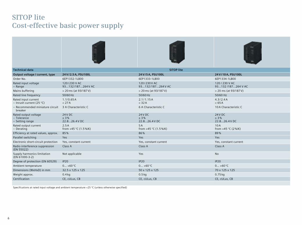
Technical data SITOP liteOutput voltage / current, type 24 V / 2.5 A, PSU100L 24 V / 5 A, PSU100L 24 V / 10 A, PSU100LOrder No. 6EP1332-1LB00 6EP1333-1LB00 6EP1334-1LB00Rated input voltage
– Range120 / 230 V AC 93...132 /187...264 V AC
120 / 230 V AC 93...132 /187...264 V AC
120 / 230 V AC93...132 /187...264 V AC
Mains buffering > 20 ms (at 93/187 V) > 20 ms (at 93/187 V) > 20 ms (at 93/187 V)Rated line frequency 50/60 Hz 50/60 Hz 50/60 HzRated input current
– Inrush current (25 °C)1.1/ 0.65 A < 27 A
2.1 / 1.15 A < 32 A
4.3 / 2.4 A < 65 A
– Recommended miniature circuit breaker
3 A Characteristic C 6 A Characteristic C 10 A Characteristic C
Rated output voltage – Tolerance – Setting range
24 V DC ± 3 % 22.8...26.4 V DC
24 V DC ± 3 % 22.8...26.4 V DC
24 V DC ± 3 % 22.8...26.4 V DC
Rated output current – Derating
2.5 A from +45 °C (1.5 %/K)
5 A from +45 °C (1.5 %/K)
10 A from +45 °C (2 %/K)
Efficiency at rated values, approx. 85 % 86 % 89 %Parallel switching Yes Yes YesElectronic short-circuit protection Yes, constant current Yes, constant current Yes, constant currentRadio interference suppression (EN 55022)
Class A Class A Class A
Supply harmonics limitation (EN 61000-3-2)
Not applicable Yes No
Degree of protection (EN 60529) IP20 IP20 IP20Ambient temperature 0… +60 °C 0… +60 °C 0… +60 °CDimensions (WxHxD) in mm 32.5 x 125 x 125 50 x 125 x 125 70 x 125 x 125Weight approx. 0.4 kg 0.5 kg 0.75 kgCertification CE, cULus, CB CE, cULus, CB CE, cULus, CB
Specifications at rated input voltage and ambient temperature +25 °C (unless otherwise specified)
SITOP lite Cost-effective basic power supply

7
Technical data Overall width 22.5 mm Overall width 30 mm Overall width 45 mm Overall width 52.5 mm
Output voltage / current, type 24 V/0.6 A, PSU100C 24 V/1.3 A, PSU100C 12 V/2 A, PSU100C 24 V/2.5 A, PSU100C 24 V/4 A, PSU100C 24 V/3.7 A, PSU100C NEC Class 2 12 V/6.5 A, PSU100C
Order No. 6EP1331-5BA00 6EP1331-5BA10 6EP1321-5BA00 6EP1332-5BA00 6EP1332-5BA10 6EP1332-5BA20 6EP1322-5BA10Rated input voltage
– Range100 – 230 V AC 85...264 V AC/ 110…300 V DC
100 – 230 V AC 85...264 V AC/ 110…300 V DC
100 – 230 V AC 85...264 V AC/ 110…300 V DC
100 – 230 V AC 85...264 V AC/ 110…300 V DC
100 – 230 V AC 85...264 V AC/ 110…300 V DC
100 – 230 V AC 85...264 V AC 110…300 V DC
100 – 230 V AC 85...264 V AC/ 110…300 V DC
Mains buffering > 20 ms (at 120/230 V AC)
> 20 ms (at 120/230 V AC)
> 20 ms (at 120/230 V AC)
> 20 ms (at 120/230 V AC)
> 20 ms (at 120/230 V AC)
> 20 ms (at 120/230 V AC)
> 20 ms (at 120/230 V AC)
Rated line frequency 50/60 Hz 50/60 Hz 50/60 Hz 50/60 Hz 50/60 Hz 50/60 Hz 50/60 HzRated input current
– Recommended miniature circuit breaker
0.28 – 0.18 A 10 A characteristic C 16 A characteristic B
0.63 – 0.31 A 10 A characteristic C 16 A characteristic B
0.63 – 0.31 A 10 A characteristic C 16 A characteristic B
1.33 – 0.67 A 10 A characteristic C 16 A characteristic B
2.25– 1.15 A 10 A characteristic C 16 A characteristic B
1.21 – 0.67 A 10 A characteristic C16 A characteristic B
1.6 – 0.75 A 10 A characteristic C 16 A characteristic B
Rated output voltag – Tolerance – Setting range
24 V DC ± 3 % –
24 V D ± 3 % 22.2...26.4 V
12 V DC ± 3 % 10.5...12.9 V DC
24 V DC ± 3 % 22.2...26.4 V DC
24 V DC ± 3 % 22.2...26.4 V DC
24 V DC ± 3 % –
12 V DC ± 3 % 10.5…12.9 V DC
Rated output current – Derating
0.6 A from +55 °C (3 %/K)
1.3 A from +55 °C (3 %/K)
2 A from +55 °C (3 %/K)
2.5 A from +50 °C (3.5 %/K)
4 A from +50 °C (3.5 %/K)
3.7 A from +50 °C (3.5 %/K)
6.5 A from +50 °C (3.5 %/K)
Efficiency at rated values, approx. 82 % 86 % 82 % 87 % 88 % 87 % 86 %No-load loss < 0.75 W < 0.75 W < 0.75 W < 0.75 W < 0.75 W < 0.75 W < 0.75 WParallel switching No Yes 2) Yes 2) Yes 2) Yes 2) No Yes 2)
Electronic short-circuit protection Yes, restart Yes, restart Yes, restart Yes, restart Yes, restart Yes, restart Yes, restartRadio interference suppression (EN 55022)
Class B Class B Class B Class B Class B Class B Class B
Supply harmonics limitation (EN 61000-3-2)
Not applicable Not applicable Not applicable Not applicable Yes Yes Yes
Degree of protection (EN 60529) IP20 IP20 IP20 IP20 IP20 IP20 IP20 Ambient temperature –20...+70 °C –20...+70 °C –20...+70 °C –20...+70 °C –20...+70 °C –20...+70 °C –20...+70 °CDimensions (WxHxD) in mm 22.5 x 80 x 100 30 x 80 x 100 30 x 80 x 100 45 x 80 x 100 52.5 x 80 x 100 52.5 x 80 x 100 52.5 x 80 x 100Weight approx. 0.12 kg 0.17 kg 0.17 kg 0.22 kg 0.32 kg 0.32 kg 0.32 kgConnections 1) Removable screw
terminalRemovable screw terminal
Removable screw terminal
Removable screw terminal
Removable screw terminal
Removable screw terminal
Removable screw terminal
Certification CE, cULus, cCSAus, CB, ATEX, cCSAus Class I Div 2, GL, ABS
CE, cULus, cCSAus, CB, ATEX, cCSAus Class I Div 2, GL, ABS
CE, cULus, cCSAus, CB, ATEX, cCSAus Class I Div 2, GL, ABS
CE, cULus, cCSAus, CB, ATEX, cCSAus Class I Div 2, GL, ABS
CE, cULus, cCSAus, CB, ATEX, cCSAus Class I Div 2, GL, ABS
CE, cULus, CB, NEC class 2, cCSAus Class I Div 2, GL, ABS
CE, cULus, cCSAus, CB, ATEX, cCSAus Class I Div 2, GL, ABS
1) Accessory: removable spring-type terminal, order no. 6EP1971-5BA002) The maximum starting current is limited to the rated output current of one power supplySpecifications at rated input voltage and ambient temperature +25 °C (unless otherwise specified)
SITOP compact Slim power supply for control boxes

8
Technical data 54 mm design 72 mm design 90 mm designOutput voltage / current 5 V/3 A 12 V/1.9 A 15 V/1.9 A 24 V/1.3 A 5 V/6.3 A 12 V/4.5 A 15 V/4 A 24 V/2.5 A 24 V/4 AOrder No. 6EP1311-1SH03 6EP1321-1SH03 6EP1351-1SH03 6EP1331-1SH03 6EP1311-1SH13 6EP1322-1SH03 6EP1352-1SH03 6EP1332-1SH43 6EP1332-1SH52Rated input voltage
– Range100 – 240 V AC 85...264 V AC/ 110...300 V DC
100 – 240 V A 85...264 V AC/ 110...300 V DC
100 – 240 V AC 85…264 V AC/ 110...300 V DC
Mains buffering > 40 ms (at 187 V) > 40 ms (at 187 V) > 40 ms (at 187 V)Rated line frequency 50/60 Hz 50/60 Hz 50/60 HzRated input current
– Inrush current (25 °C)0.36 – 0.22 A < 26 A
0.53 – 0.30 A < 25 A
0.63 – 0.33 A < 25 A
0.70 – 0.35 A < 25 A
0.71 – 0.37 A < 50 A
1.13 – 0.61 A < 55 A
1.24 – 0.68 A < 55 A
1.22 – 0.66 A < 46 A
1.95 – 0.97 A < 30 A
– Recommended miniature circuit breaker
10 A characteristic C resp. 16 A characteristic B 10 A characteristic C resp. 16 A characteristic B 10 A char. C resp. 16 A char. B
Rated output voltage – Tolerance – Setting range
5 V DC ± 3 % 4.6...5.4 V DC
12 V DC 10.5...16.1 V DC
15 V DC 10.5...16.1 V DC
24 V DC 22.2...26.4 V DC
5 V DC ± 3 % 4.6...5.4 V DC
12 V DC 10.5...16.1 V DC
15 V DC 10.5...16.1 V DC
24 V DC 22.2...26.4 V DC
24 V DC ± 3 % 22.2...26.4 V DC
Output current – rated value – Derating
3.0 A from +55 °C (2 %/K)
1.9 from +55 °C (2 %/K
1.9 A from +55 °C (2 %/K)
1.3 A from +55 °C (2 %/K)
6.3 A from +55 °C (2 %/K)
4.5 A from +55 °C (2 %/K)
4.0 A from +55 °C (2 %/K)
2.5 A from +55 °C (2 %/K)
4.0 A from +55 °C (2 %/K)
Efficiency at rated values, approx. 77 % 80 % 80 % 85 % 83 % 85 % 85 % 88 % 89 %No-load loss < 1.5 W < 1.8 W < 2 W < 2 W < 1.5 W < 1.9 W < 2.3 W < 1.8 W < 2 WParallel switching Yes Yes YesElectronic short-circuit protection Yes, constant current Yes, constant current Yes, constant currentRadio interference suppression (EN 55022)
Class B Class B Class B
Supply harmonics limitation (EN 61000-3-2)
Not applicable Not applicable Yes
Degree of protection (EN 60529) IP20 IP20 IP20Ambient temperature –20… +70 °C –20… +70 °C –20… +70 °CDimensions (WxHxD) in mm 54 x 90 x 55 72 x 90 x 55 90 x 90 x 55Weight approx. 0.17 kg 0.25 kg 0.34 kgCertification CE, cULus, CB,
FM, ATEX, cCSAus Class I Div 2, GL, ABS
CE, cULus, CB, FM, ATEX, cCSAus Class I Div 2, GL, ABS
CE, cULus, CB, FM, ATEX, cCSAus Class I Div 2, GL, ABS
CE, cULus, CB, FM, ATEX, SEMI F47, NEC Class 2, cCSAus Class I Div 2, GL, ABS, DNV, BV, LRS
CE, cULus, CB, FM, ATEX, cCSAus Class I Div 2, GL, ABS
CE, cULus,CB, FM, ATEX, cCSAus Class I Div 2, GL, ABS
CE, cULus, CB, FM, ATEX, cCSAus Class I Div 2, GL, ABS
CE, cULus, CB, FM, ATEX, SEMI F47, NEC Class2, cCSAus Class I Div 2, GL, ABS, DNV, BV, LRS
CE, cULus, CB, FM, ATEX, SEMI F47, cCSAus Class I Div 2, GL, ABS, DNV, BV, LRS
Specifications at rated input voltage and ambient temperature +25 °C (unless otherwise specified) 1) Shipment after the existing products have been sold (est. June 2014)
LOGO!Power Flat power supply for distribution boards
New! In LOGO! 8 design 1)

9
Technical data SIMATIC S7-1200 design SIMATIC S7-300 design SIMATIC S7-1500 design SIMATIC ET200 pro PS
Output voltage / curr., type 24 V/2.5 A, PM1207 24 V/2 A, PS307 24 V/5 A, PS307 24 V/10 A, PS307 24 V/3 A, PM1507 24 V/8 A, PM1507 24 V/8 AOrder No. 6EP1332-1SH71 6ES7307-1BA01-0AA0 6ES7307-1EA01-0AA0 6ES7307-1KA02-0AA0 6EP1332-4BA00 6EP1333-4BA00 6ES7 148-4PC00-0HA0
Rated input voltage 120/230 V AC automatic range selection
120/230 V AC automatic range selection
120/230 V AC automatic range selection
120/230 V AC automatic range selection
120/230 V AC automatic range selection
120/230 V AC automatic range selection
400 – 480 V 3 AC
– Range 85…132 /176…264 V AC 85…132 /170…264 V AC 85…132 /170…264 V AC 85…132 /170...264 V AC 85…132 /176...264 V AC 85…132 /176...264 V AC 340…550 V 3 AC
Mains buffering > 20 ms (at 93/187 V) > 20 ms (at 93/187 V) > 20 ms (at 93/187 V) > 20 ms (at 93/187 V) > 20 ms (at 93/187 V) > 20 ms (at 93/187 V) 3 ms (at 400 V)
Rated line frequency 50/60 Hz 50/60 Hz 50/60 Hz 50/60 Hz 50/60 Hz 50/60 Hz 50/60 Hz
Rated input current 1.2/0.67 A 0.9/0.5 A 2.3/1.2 A 4.2/1.9 A 1.4 A/0.8 A 3.7 A/1.7 A 1 A
– Inrush current (25 °C) < 13 A < 22 A < 20 A < 55 A < 23 A < 67 A < 40 A
– Recommended miniature circuit breaker
16 A charakt. B, 10 A charakt. C
3 A charakt. C 6 A charakt. C 10 A charakt. C from 6 A charakt. C,from 10 A charakt. B
from 10 A charakt. C,from 16 A charakt. B
3RV2021-4NA10
Rated output voltage 24 V DC 24 V DC 24 V DC 24 V DC 24 V DC 24 V DC 24 V DC – Tolerance ± 3 % ± 3 % ± 3 % ± 3 % ± 3 % ± 3 % – 5 %/+3 % – Setting range – – – – – – – – On/off switch No Yes Yes Yes Yes Yes No
Rated output current 2.5 A 2 A 5 A 10 A 3 A 8 A 8 A– Overload characteristics
(extra power for 5 s/min)– – – – 4.5 A 12 A –
Efficiency at rated values, approx.
83 % 84 % 86 % 90 % 87 % 91 % 88 %
Parallel switching Yes Yes Yes Yes Yes Yes No
Electr. short-circuit protection Yes, constant current char. Yes, restart Yes, restart Yes, restart Yes, restart Yes, restart Yes, restart
Radio interference suppression (EN 55022)
Class B Class B Class B Class B Class B Class B EN 61000-6-4 (Class A)
Supply harmonics limitation (EN 61000-3-2)
Not applicable Not applicable Yes Yes Not applicable Yes No
Degree of protection (EN 60529) IP20 IP20 IP20 IP20 IP20 IP20 IP67, UL: encl. type 5 indoor
Ambient temperature 0…+60 °C 0…+60 °C 0…+60 °C 0…+60 °C 0…+60 °C 0…+60 °C –25°C...+55°C
Installation DIN rail or wall mounting
Can be mounted on S7 rail. Mounting adapter for DIN rail 35 x15 mm: 6EP1971-1BA00
on S7-1500 system carrier on S7-1500 system carrier Screw mounting, e.g., on SIMATIC ET 200pro system rail
Mass (B x H x T) in mm 70 x 100 x 75 40 x 125 x 120 60 x 125 x 120 80 x 125 x 120 50 x 147 x 135 75 x 147 x 135 310 x 135,5 w/o connector x 90
Weight approx. 0.3 kg 0.4 kg 0.6 kg 0.8 kg 0.45 kg 0.74 kg 2.8 kg
Certification CE, cULus, CB, FM, ATEX, cCSAus Class I Div 2, GL, ABS, DNV
CE, cULus, ATEX, cULus Class I Div 2, GL, ABS, DNV CE, cULus, CB, FM, ATEX, BV, cULus Class l Div 2, pend-ing: GL, ABS
CE, pending: ULus 508
Specifications at rated input voltage and ambient temperature +25 °C (unless otherwise specified)
SITOP in SIMATIC design

10
Technical data SITOP smart 1-phaseOutput voltage/current, type 24 V/2.5 A, PSU100S 24 V/5 A, PSU100S 12 V/7A, PSU100S 24 V/10 A, PSU100S 12 V/14 A, PSU100S 24 V/20 A, PSU100SOrder No. 6EP1 332-2BA20 6EP1 333-2BA20 6EP1 322-2BA00 6EP1 334-2BA20 6EP1 323-2BA00 6EP1336-2BA10Rated input voltage 120/230 V AC 120/230 V AC 120/230 V AC 120/230 V AC 120/230 V AC 120/230 V AC
– Rate 85...132/170...264 V AC, automatic range switching 85...132/176...264 V ACMains buffering > 20 ms (at 93/187 V) > 20 ms (at 93/187 V) > 20 ms (at 93/187 V) > 20 ms (at 93/187 V) > 20 ms (at 93/187 V) > 20 ms (at 120/230 V)Rated line frequency 50/60 Hz 50/60 Hz 50/60 Hz 50/60 Hz 50/60 Hz 50/60 HzRated input current
– Inrush current (25 °C) – Recommended miniature circuit breaker
1.25 A/0.74 A < 33 from 3 A, characteristic C
2.34 A/1.36 A < 40 A from 6 A, characteristic C
1.73 A/ 0.99 A < 45 A from 6 A, characteristic C
4.49 A/1.91 A < 60 A from 10 A, characteristic C
3.24 A/1.41 A < 60 A from 10 A, characteristic C
7.5/3.5 A < 11 A from 10 A, characteristic C
Rated output voltage – Tolerance – Setting range
24 V DC ± 3 % 22.8...28 V DC
24 V DC ± 3 % 22.8...28 V DC
12 V DC ± 3 % 11.5…15.5 V DC
24 V DC ± 3 % 22.8...28 V DC
12 V DC ± 3 % 11.5…15.5 V DC
24 V DC ± 3 % 22.8...28 V DC
Rated output current – Permanently up to +45 °C – Overload behavior (extra power for 5 s/min)
– Derating
2.5 A 3 A 3.75 A from +60 °C (3%/ K)
5 A 6 A 7.5 A from +60 °C (3%/ K)
7 A 7 A 10.5 A from +55 °C (5%/ K)
10 A 12 A 15 A from +60 °C (3%/ K)
14 A 14 A 21 A from +55 °C (5%/ K)
20 A 24 A 30 A from +60 °C (5 %/K)
Efficiency at rated values, approx.
85 % 88 % 84 % 90 % 87 % 90 %
Parallel switching Yes Yes Yes Yes Yes YesElectronic short-circuit protection
Yes, constant current Yes, restart
Radio interference suppression (EN 55022)
Class B Class B Class B Class B Class B Class B
Supply harmonics limitation (EN 61000-3-2)
Not applicable Yes Yes Yes Yes Yes
Degree of protection (EN 60529)
IP20 IP20 IP20 IP20 IP20 IP 20
Ambient temperature –10…+70 °C –10…+70 °C –10…+70 °C –10…+70 °C –10…+70 °C 0...+70 °CDimensions (WxHxD) in mm 32.5 x 125 x 125 50 x 125 x 125 50 x 125 x 125 70 x 125 x 125 70 x 125 x 125 115 x 145 x 150Weight approx. 0.32 kg 0.5 kg 0.5 kg 0.8 kg 0.8 kg 2.4 kgCertification CE, cULus, CB, ATEX,
cCSAus Class I Div 2, GL, BVCE, cULus, CB, ATEX, cCSAus Class I Div 2, GL, BV
CE, cULus, CB, ATEX, cCSAus Class l Div 2, GL
CE, cULus, ATEX, cCSAus Class l Div 2, GL, BV
CE, cULus, CB, ATEX, cCSAus Class l Div 2, GL
CE, cULus, CB, ATEX, cCSAus Class I Div 2, GL
Specifications at rated input voltage and ambient temperature at +25 °C (unless otherwise specified)
SITOP smart Powerful standard power supply

11
Technical data SITOP smart 3-phaseOutput voltage / current, type 24 V/10 A, PSU300S 24 V/20 A, PSU300S 24 V/40 A, PSU300SOrder No. 6EP1434-2BA10 6EP1436-2BA10 6EP1437-2BA20Rated input voltage 400 – 500 V 3 AC 400 – 500 V 3 AC 400 – 500 V 3 AC
– Range 340…550 V 3 AC 340…550 V 3 AC 340…550 V 3 ACMains buffering > 6 ms (at 400 V) > 6 ms (at 400 V) > 6 ms (at 400 V)Rated line frequency 50/60 Hz 50/60 Hz 50/60 HzRated input current
– Inrush current (25 °C) – Recommended miniature circuit breaker
0.7 – 0.5 A < 36 A From 6 – 16 A charact. C 3-ph. coupled or 3 RV2011-1DA10 or 3 RV2711-1DD10
1.2 – 1.0 A < 36 A From 6 – 16 A charact. C 3-ph. coupled or 3 RV2011-1DA10 or 3 RV2711-1DD10
2,0 – 1,5 A < 60 A From 10 – 16 A charact. C 3-ph. coupled or 3 RV2011-1DA10 or 3 RV2711-1DD10
Rated output voltage – Tolerance – Setting range
24 V DC ± 3 % 24...28 V DC
24 V DC ± 3 % 24...28 V DC
24 V DC ± 3 % 24...28 V DC
Overload characteristics – Permanently up to +45 °C – Overload behavior (extra power for 5 s/min)
– Derating
10 A 12 A 15 A –
20 A 24 A 30 A from +60 °C (5 %/K)
40 A 48 A 60 A from +60 °C (2.5 %/K)
Efficiency at rated values, approx. 91 % 91 % 91.5 %Parallel switching Yes Yes YesElectronic short-circuit protection Yes, restart Yes, restart Yes, restartRadio interference suppression (EN 55022)
Class B Class B Class B
Supply harmonics limitation (EN 61000-3-2)
Yes Yes Yes
Degree of protection (EN 60529)
IP20 IP20 IP20
Ambient temperature 0...+70 °C 0...+70 °C 0...+70 °CDimensions (WxHxD) in mm 90 x 145 x 150 90 x 145 x 150 150 x 145 x 150Weight approx. 1.6 kg 1.6 kg 3.7 kgCertification CE, cULus, CB, ATEX, cCSAus Class I Div 2, GL CE, cULus, CB, ATEX, cCSAus Class I Div 2, GL CE, cULus, CB, ATEX, cCSAus Class I Div 2, GL
Specifications at rated input voltage and ambient temperature at +25 °C (unless otherwise specified)

12
Technical data SITOP modular 1-phase and 2-phase1)
Output voltage / current, type 24 V/5 A, PSU200M 24 V/10 A, PSU200M 24 V/20 A, PSU100M 24 V/20 A, PSU400M 24 V/40 A, PSU100MOrder No. 6EP1333-3BA002) 6EP1334-3BA002) 6EP1336-3BA10 6EP1536-3AA00 6EP1337-3BA00Rated input voltage
– Range120 – 230/230 – 500 V AC 85…264/176…550 V AC
120 – 230/230 – 500 V AC 85…264/176…550 V AC
120 – 230 V AC 85…275 V AC or 88…350 V DC
600 V DC 200...900 V DC, start-up from approx. 400 V
120/230 V AC 85...132/176...264 V AC, start-up from 95/190 V
Mains buffering > 25 ms (at 120/230 V) > 25 ms (at 120/230 V) > 25 ms (at 120/230 V) > 20 ms (at 230 V)Rated line frequency 50/60 Hz 50/60 Hz 50/60 Hz 50/60 HzRated input current
– Inrush current (25 °C) – Recommended miniature circuit breaker
2.2 – 1.2/1.2 – 0.61 A < 35 A 6 A charact. C or 3RV2011-1xA10
4.4 – 2.4/2.4 – 1.1 A < 35 A 6 A charact. C or 3RV2011-1xA10
4.6 – 2.5 A < 20 A 10 A charact. C or 3RV1021-1xA10
0.85 A < 8 A
15.0/8.0 A < 125 A 20 A Charakt. C or 3RV2011-xxA10
Rated output voltage – Tolerance – Setting range
24 V DC ± 3 % 24…28.8 V DC
24 V DC ± 3 % 24…28.8 V DC
24 V DC ± 3 % 24…28.8 V DC
24 V DC ± 3 % 24…28.8 V DC
24 V DC ± 3 % 24…28.8 V DC
Rated output current 5 A 10 A 20 A 20 A 40 A – Overload behavior (power boost for 25 ms)
15 A 30 A 60 A 120 A
– Overload behavior (extra power for 5 s/min)
30 A 30 A
– Derating – from +60 °C (2-3,5 %/K) from +60 °C (3 %/K) from +60 °C (5.5 %/K), 200…300 V DC, 820…900 V DC
from +60 °C (2,5%/K)
Efficiency at rated values, approx. 87 % 87 % 93 % 95 % 88 %Parallel switching Yes, output characteristic can be switched to parallel operationElectronic short-circuit protection Yes, constant current or latching shutdown selectable. Constant current: approx. 1.15 x rated output currentRadio interference suppression (EN 55022)
Class B Class B Class B Class A (emission) Class B
Supply harmonics limitation (EN 61000-3-2)
Yes Yes Yes No No
Degree of protection (EN 60529) IP20 IP20 IP20 IP 20 IP20Ambient temperature –25…+70 ° C –25…+70 ° C –25…+70 °C –25…+70 ° C 0…+70 ° CDimensions (WxHxD) in mm 70 x 125 x 125 90 x 125 x 125 90 x 125 x 125 90 x 125 x 125 240 x 125 x 125Weight approx. 1.2 kg 1.4 kg 1.5 kg 1.2 kg 2.9 kgCertification CE, cULus, ATEX, UL Class I Div 2, SEMI F472), GL, ABS CE, cULus, ATEX, UL Class I Div 2,
GL, ABSCE, cULus, CB, GL CE, cULus, ATEX, cCSAus Class I
Div 2, SEMI F473)
1) Connection to two phases of a three-phase supply system 2) At input voltage 208 to 230 VAC 3) In conjunction with two buffer modules
SITOP modular Technology power supply for demanding solutions

13
SITOP modular 3-phase SITOP modular 3-phase, 48 V24 V/20 A, PSU300M 24 V/40 A, PSU300M 48 V/10 A, PSU300M 48 V/20 A, PSU300M6EP1436-3BA10 6EP1437-3BA10 6EP1456-3BA00 6EP1457-3BA00400 – 500 V 3 AC 320…575 V 3 AC
400 – 500 V 3 AC 320…575 V 3 AC
400 – 500 V 3 AC 320…575 V 3 AC
400 – 500 V 3 AC 320...550 V 3 AC, start-up from 340 V
> 15 ms (at 400 V) > 15 ms (at 400 V) > 15 ms (at 400 V) > 6 ms (at 400 V)50/60 Hz 50/60 Hz 50/60 Hz 50/60 Hz1.2 – 1.0 A < 18 A 6 – 16 A charact. C 3-ph. coupled or 3RV2011-1DA10 or 3RV2711-1DD10
2.6 – 2.1 A < 56 A 10 – 16 A charact. C 3-ph. coupled or 3RV2011-1DA10 or 3RV2711-1DD10
1.2 – 1.0 A < 18 A 6 – 16 A charact. C 3-ph. coupled or 3RV2011-1DA10 or 3RV2711-1DD10
2.2 A (with 400 V) < 70 A 10 – 16 A charact. C 3-ph. coupled or 3RV2011-1DA10 or 3RV2711-1DD10
24 V DC ± 3 % 24...28.8 V DC
24 V DC ± 3 % 24...28.8 V DC
48 V DC ± 3 % 42…56 V DC
48 V DC ± 3 % 42…56 V DC
20 A 40 A 10 A 20 A60 A 120 A 23A 60A
30 A 60 A 15 A
from +60 °C (3 %/K) from +60 °C (3.8 %/K) from +60 °C (3 %/K)
93 % 93 % 93 % 90 %Yes, output characteristic can be switched to parallel operationYes, constant current or latching shutdown selectable. Constant current: approx. 1.15 x rated output currentClass B Class B Class B Class BYes Yes Yes Yes
IP20 IP20 IP 20 IP20–25…+70 °C –25…+70 °C –10...+70 °C 0…+60 °C70 x 125 x 125 150 x 125 x 150 70 x 125 x 125 240 x 125 x 1251.2 kg 3.4 kg 1.2 kg 3.2 kgCE, cULus, CB, ATEX, cCSAus Class I Div 2, SEMI F47, GL, ABS
CE; cULus, CB, ATEX, cCSAus Class I Div 2, SEMI F47, GL, ABS
CE; cULus, CB, ATEX, cCSAus Class I Div 2, GL, ABS CE, UL, CSA, GL, ABS
Specifications at rated input voltage and ambient temperature at +25 °C (unless otherwise specified)
14
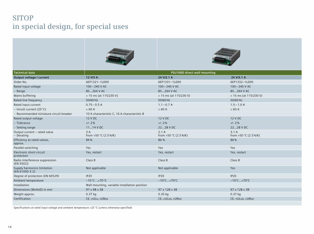
Technical data PSU100D direct wall mountingOutput voltage / current 12 V/3 A 24 V/2.1 A 24 V/3.1 AOrder No. 6EP1321–1LD00 6EP1331–1LD00 6EP1332–1LD00Rated input voltage 100 – 240 V AC 100 – 240 V AC 100 – 240 V AC
– Range 85...264 V AC 85...264 V AC 85...264 V ACMains buffering > 15 ms (at 115/230 V) > 15 ms (at 115/230 V) > 15 ms (at 115/230 V)Rated line frequency 50/60 Hz 50/60 Hz 50/60 HzRated input current 0.75 – 0.5 A 1.1 – 0.7 A 1.5 – 1.0 A
– Inrush current (25 °C) < 60 A < 60 A < 60 A – Recommended miniature circuit breaker 10 A characteristic C, 16 A characteristic B
Rated output voltage 12 V DC 12 V DC 12 V DC – Tolerance +/- 2 % +/- 2 % +/- 2 % – Setting range 11…14 V DC 22...28 V DC 22...28 V DC
Output current – rated value – Derating
3 A from +50 °C (2.5 %/K)
2.1 A from +50 °C (2.5 %/K)
3.1 A from +50 °C (2.5 %/K)
Efficiency at rated values, approx.
84 % 86 % 86 %
Parallel switching Yes Yes YesElectronic short-circuit protection
Yes, restart Yes, restart Yes, restart
Radio interference suppression (EN 55022
Class B Class B Class B
Supply harmonics limitation (EN 61000-3-2)
Not applicable Not applicable Yes
Degree of protection (EN 60529) IP20 IP20 IP20Ambient temperature –10 °C ...+70 °C –10°C...+70°C –10°C...+70°CInstallation Wall mounting, variable installation positionDimensions (WxHxD) in mm 97 x 98 x 38 97 x 128 x 38 97 x 128 x 38Weight approx. 0.37 kg 0.35 kg 0.37 kgCertification CE, cULu, cURus CE, cULus, cURus CE, cULus, cURus
Specifications at rated input voltage and ambient temperature +25 °C (unless otherwise specified)
SITOP in special design, for special uses

15
Technical data PSU100D direct wall mountingOutput voltage / current 24 V/4.1 A 12 V/8.3 A 24 V/6.2 A 24 V/12.5 AOrder No. 6EP1332-1LD10 6EP1322-1LD00 6EP1333-1LD00 6EP1334-1LD00Rated input voltage 100 – 240 V AC 100 – 240 V AC 100 – 240 V AC 100 – 240 V AC
– Range 85...264 V AC 85...264 V AC 85...264 V AC 85...264 V ACMains buffering > 15 ms (at 115/230 V) > 15 ms (at 115/230 V) > 15 ms (at 115/230 V) > 15 ms (at 115/230 V)Rated line frequency 50/60 Hz 50/60 Hz 50/60 Hz 50/60 HzRated input current 2.0 – 1.1 A 2.0 – 1.1 A 3.1 – 2.0 A 4.0 – 2.0 A
– Inrush current (25 °C) < 75 A < 75 A < 75 A < 60 A – Recommended miniature circuit breaker
10 A charakteristic C, 16 A charakteristic B
Rated output voltage 24 V DC 12 V DC 24 V DC 24 V DC – Tolerance +/- 2 % +/- 2 % +/- 2 % +/- 2 % – Setting range 22...28 V DC 11…14 V DC 22...28 V DC 22...28 V DC
Output current – rated value – Derating
4.1 A from +50 °C (2.5 %/K)
8.3 A from +50 °C (2.5 %/K)
6.2 A from +50 °C (2.5 %/K)
12.5 A from +50 °C (2.5 %/K)
Efficiency at rated values, approx.
86 % 84 % 86 % 86 %
Parallel switching Yes Yes Yes YesElectronic short-circuit protection
Yes, restart Yes, restart Yes, restart Yes, restart
Radio interference suppression (EN 55022
Class B Class B Class B Class B
Supply harmonics limitation (EN 61000-3-2)
Yes Yes No Yes
Degree of protection (EN 60529) IP20 IP20 IP20 IP20Ambient temperature –10°C...+70°C –10°C...+70°C –10°C...+70°C –10°C...+70°CInstallation Wall mounting, variable installation positionDimensions (WxHxD) in mm 97 x 158 x 38 97 x 158 x 38 97 x 178 x 38 105 x 199 x 41Weight approx. 0.50 kg 0.57 kg 0.55 kg 0.81 kgCertification CE, cULus, cURus CE, cULus, cURus CE, cULus, cURus CE, cULus, cURus
Specifications at rated input voltage and ambient temperature +25 °C (unless otherwise specified)

16
Technical data SITOP flat design SITOP PSU300E SITOP PSU100P SITOP PSU300P in IP67Output voltage / current 24 V/5 A 24 V/10 A 24 V/5 A 24 V/5 A 24 V/8 A 24 V/8 AOrder No. 6EP1333-1AL12 6EP1334-1AL12 6EP1433-1AL12 6EP1333-7CA00 6EP1334-7CA00 6EP1433-2CA00Rated input voltage 120/230 V AC 120/230 V AC 3 AC 400 V AC 120/230 V (automatic range switching) 400 – 480 V 3 AC
– Range 85...132/170...264 V AC 85...132/170...264 V AC 3 AC 320…480 V AC 85… 132 V/ 170… 264 V 340…550 V 3 ACMains buffering > 20 ms (at 93/187 V) > 20 ms (at 93/187 V) > 50 ms (at 400 V) > 40 ms (at I A rated) > 40 ms (at I A rated) 3 ms (at 400 V)Rated line frequency 50/60 Hz 50/60 Hz 50/60 Hz 50/60 Hz 50/60 Hz 50/60 HzRated input current 2.2/1.2 A 4/2.5 A 0.36 A 2,25 A/ 1,24 A 3,5 A/ 1,52 A 1 A
– Inrush current (25 °C) < 32 A < 65 A < 15 A < 15 A < 15 A < 40 A – Recommended miniature circuit breaker
6 A charact. C 10 A charact. C 6 – 10 A charact. C ≥ 6 A charact. C/B ≥ 6 A charact. C/B 3RV2011-1DA10
Rated output voltage 24 V DC 24 V DC 24 V DC 24 V DC 24 V DC 24 V DC – Tolerance ± 1 % ± 1 % ± 3% ± 3% ± 3% –5 %/+3 % – Setting range 22...29 V DC 22...29 V DC 22...29 V DC – – –
Output current – rated value 5 A 10 A 5 A 5 A 8 A 8 A – Derating – – – – – –
Efficiency at rated values, approx. 88 % 89 % 90 % 90 % 93 % 88 %Status signaling No No LED green for “DC ok”.
Signaling contact for “DC ok”
LED green for „DC ok“ and flashing red for „overload/short circuit.” Signaling contact for „DC ok“
LED green for „DC ok“. Signaling contact for „DC ok“ and „overheating“
Parallel switching Yes Yes No Yes, 2 units Yes, 2 units NoElectronic short-circuit protection Yes, restart Yes, restart Yes, restart Yes, restart Yes, restart Yes, restartRadio interference suppression (EN 55022)
Class B Class B Class A Class B Class B EN 61000-6-4 (Class A)
Supply harmonics limitation (EN 61000-3-2)
No No Yes Yes Yes No
Degree of protection (EN 60529) IP20 IP20 IP20 IP67, UL: enclosure type 4 indoor
IP67, UL: enclosure type 4 indoor
IP67, UL: enclosure type 5 indoor
Ambient temperature 0...+60 °C 0...+60 °C 0…+60 °C -25...+60°C -25...+60°C –25 °C...+55 °CInstallation DIN rail DIN rail DIN rail Screw mounting Screw mounting Screw mounting, e.g., on
SIMATIC ET 200pro system railDimensions (WxHxD) in mm 160 x 130 x 60 160 x 130 x 60 42 x 125 x 125 120 x 181 (w/o connector) x 60,5 310 x 135,5
(w/o connector) x 90Weight approx. 0.6 kg 0.72 kg 0.6 kg 1,1 kg 1,1 kg 2.8 kgCertification CE, cULus CE, cULus CE, cULus CE, cULus CE, cULus CE, pending: ULus508
Specifications at rated input voltage and ambient temperature +25 °C (unless otherwise specified)
SITOP in special design, for special uses
new!
17
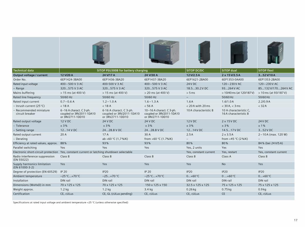
Technical data SITOP PSU300B for battery charging SITOP DC/DC SITOP dual SITOP flexiOutput voltage / current 12 V/20 A 24 V/17 A 24 V/30 A 12 V/2.5 A 2 x 15 V/3.5 A 3…52 V/10 A Order No. 6EP1424-3BA00 6EP1436-3BA20 6EP1437-3BA20 6EP1621-2BA00 6EP1353-0AA00 6EP1353-2BA00 Rated input voltage 400 – 500 V 3 AC 400-500 V 3 AC 400 – 500 V 3 AC 24 V DC 120 – 230 V AC 120 – 230 V AC
– Range 320…575 V 3 AC 320…575 V 3 AC 320…575 V 3 AC 18.5...30.2 V DC 93...264 V AC 85…132 V/170...264 V AC Mains buffering > 15 ms (at 400 V) > 15 ms (at 400 V) > 20 ms (at 400 V) > 5 ms > 10/40 ms (at 120/187 V) > 10 ms (at 93/187 V) Rated line frequency 50/60 Hz 50/60 Hz 50/60 Hz – 50/60 Hz 50/60 Hz Rated input current 0.7 – 0.6 A 1.2 – 1.0 A 1.6 – 1.3 A 1.6 A 1.6/1.0 A 2.2/0.9 A
– Inrush current (25 °C) < 18 A < 18 A < 56 A < 20 A with 20 ms < 30 A, < 3 ms < 32 A – Recommended miniature circuit breaker
6 –16 A charact. C 3-ph. coupled or 3RV2011-1DA10 or 3RV2711-1DD10
6-16 A charact. C 3-ph. coupled or 3RV2011-1DA10 or 3RV2711-1DD10
10 –16 A charact. C 3-ph. coupled or 3RV2011-1DA10 or 3RV2711-1DD10
10 A characteristic B 10 A characteristic C, 16 A characteristic B
Rated output voltage 12 V DC 24 V DC 24 V DC 12 V DC 2 x 15 V DC 24 V DC – Tolerance ± 3 % ± 3 % ± 3 % ± 3 % ± 3 % ± 1 % – Setting range 12…14 V DC 24...28.8 V DC 24...28.8 V DC 12…14 V DC 14.5…17 V DC 3…52 V DC
Rated output current 20 A 17 A 30 A 2.5 A 2 x 3.5 A 2 – 10 A (max. 120 W) – Derating – ab +60 °C (1,7 %/K) from +60 °C (1.7%/K) – from +45 °C (2 %/K) –
Efficiency at rated values, approx. 88 % 93 % 93 % 80 % 80 % 84 % (bei 24 V/5 A) Parallel switching Yes Yes Yes Yes, 2 units Yes YesElectronic short-circuit protection Yes, constant current or latching shutdown selectable Yes, constant current Yes, restart Yes, constant currentRadio interference suppression (EN 55022)
Class B Class B Class B Class B Class A Class B
Supply harmonics limitation (EN 61000-3-2)
Yes Yes Yes Yes No Yes
Degree of protection (EN 60529) IP 20 IP20 IP 20 IP20 IP20 IP20 Ambient temperature –25 °C...+70 °C –25…+70 °C –25 °C...+70 °C 0…+60 °C 0 ...+60 °C 0…+60 °C Installation DIN rail DIN rail DIN rail DIN rail DIN rail DIN railDimensions (WxHxD) in mm 70 x 125 x 125 70 x 125 x 125 150 x 125 x 150 32.5 x 125 x 125 75 x 125 x 125 75 x 125 x 125 Weight approx. 1.2 kg 1.2 kg 3.4 kg 0.26 kg 0.75 kg 0.9 kg Certification CE, cULus CE, GL (cULus pending) CE, cULus CE, cULus CE CE, cULus
Specifications at rated input voltage and ambient temperature +25 °C (unless otherwise specified)

18
Redundancy modules for security against failure of power supply units
SITOP redundancy modules provide additional protection against failures of the 24-V supply. Because the two power supplies are decoupled via a redundancy module, one failed power supply unit has no effect on the 24-V supply. The redundancy module continually monitors the feeding power supply units and when one unit fails, the other unit automatically takes over the feed, thereby safeguarding the 24-V supply. In addition, a signal is sent via a signaling contact that can be evaluated by a controller, PC, or control system.
A reliable power supply system is the basis for any production process or plant.
So it is only makes sense to not only carefully select the power supply unit, but
protect the 24-V supply against faults in the input or output circuit. SITOP offers
suitable add-on modules for this purpose.
SITOP add-on modules for increasing availability
Redundancy modules
Redundant design of the power supply syste
Power supply system
Power supply system
Redundancy module
Configuration with redundancy module
Your benefits with the redundancy module:
• Highly secure 24-V supply thanks to a redundant design
• Reliable supply even when one power supply fails
• Compact redundancy modules for power supply units up to 40 A
• 24 V/NEC class2 redundancy module limited to 100 VA
• Diagnostics signals via LEDs and signaling contacts
• Adjustable switching threshold for LEDs and signaling contacts24 V DC

19
Selectivity modules to monitor 24-V feeders
In today’s plants, all 24-V loads receive power from one shared, regulated, switched-mode power supply. To prevent faults in one load from disabling the entire plant, the 24-V supply circuit is divided into individual feeders and, in the case of a fault, selectively disconnected. The selectivity module monitors the current for each feeder and reliably prevents supply voltage failure, thus avoiding total failure of the plant. Thanks to channel-specific signaling and evaluation by means of SIMATIC S7 and SIMOTION function blocks, fault detection is extremely fast and downtimes are reduced.
Buffer module bridges brief power failures
Power failures usually last only for fractions of a second – however, they can cause time- and cost-intensive damage to sensitive production areas. Used in combination with SITOP smart and modular power supply units, the buffer module bridges short-duration voltage dips with its electrolytic capacitors and reliably preserves interruption-free operation.
Buffer module
Bridging for up to a period of seconds
Selectivity modules
Electronic monitoring of 24-V feeders
Your benefits with the selectivity module:
• Protection against overloads and short circuits in the 24-V circuit
• Safe tripping of circuit breakers regardless of line lengths or cross-sections
• Four load feeders per module• Variants with an adjustable output
current variable from 0.5 to 3 A or from 3 to 10 A
• Possibility of sequential startup of feeders to reduce inrush current
• Diagnosis via a common signaling contact or single-channel signal
• Evaluation via free SIMATIC S7 or SIMOTION function block for modules with single-channel signaling
Your benefits with the buffer module:
• Inexpensive protection against power failure up to max. 10 seconds
• Support of power supply unit for temporarily increased power requirements
• High load current up to 40 A
Configuration with selectivity module Configuration with buffer module
Power supply Selectivity module
PLC HMI Actuators Sensors
24 V DC
24 V DC
SITOP smart and modular power
supply
Buffer module
20
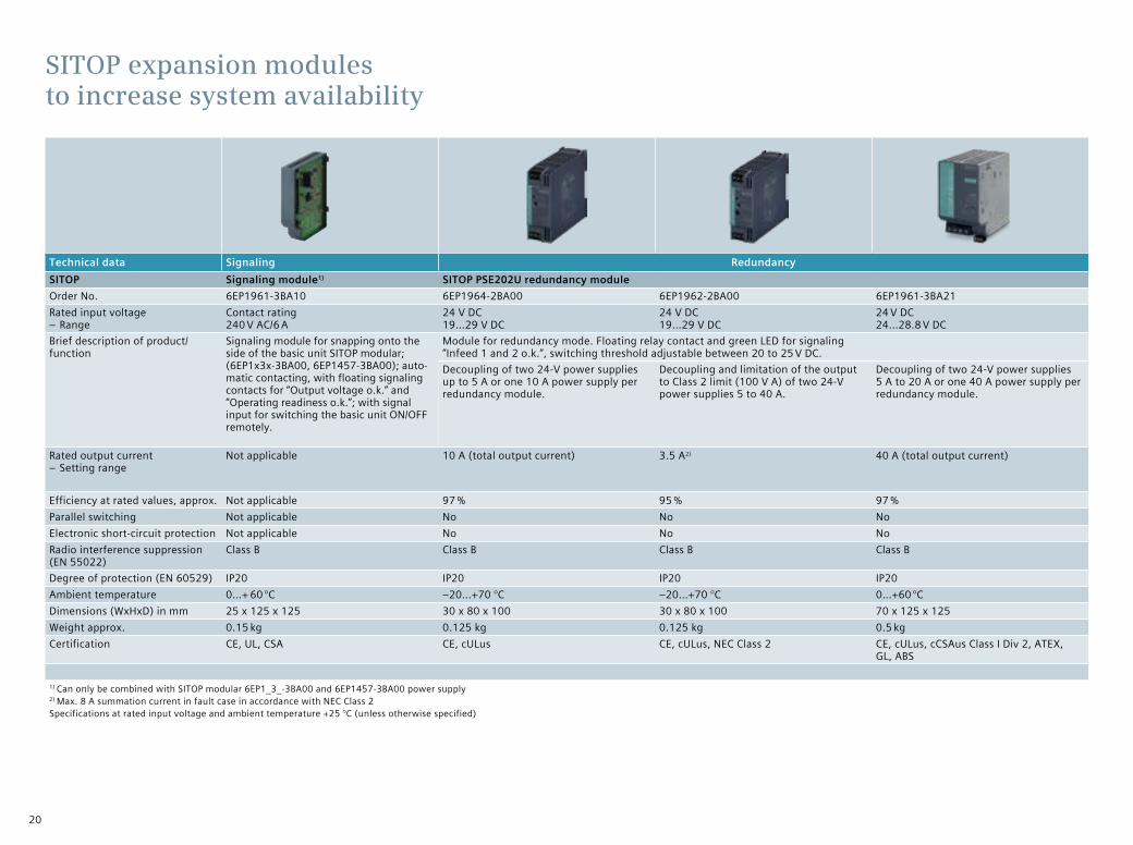
Technical data Signaling RedundancySITOP Signaling module1) SITOP PSE202U redundancy moduleOrder No. 6EP1961-3BA10 6EP1964-2BA00 6EP1962-2BA00 6EP1961-3BA21Rated input voltage
– RangeContact rating 240 V AC/6 A
24 V DC 19…29 V DC
24 V DC 19…29 V DC
24 V DC 24…28.8 V DC
Brief description of product/ function
Signaling module for snapping onto the side of the basic unit SITOP modular; (6EP1x3x-3BA00, 6EP1457-3BA00); auto-matic contacting, with floating signaling contacts for “Output voltage o.k.” and “Operating readiness o.k.”; with signal input for switching the basic unit ON/OFF remotely.
Module for redundancy mode. Floating relay contact and green LED for signaling “Infeed 1 and 2 o.k.“, switching threshold adjustable between 20 to 25 V DC. Decoupling of two 24-V power supplies up to 5 A or one 10 A power supply per redundancy module.
Decoupling and limitation of the output to Class 2 limit (100 V A) of two 24-V power supplies 5 to 40 A.
Decoupling of two 24-V power supplies 5 A to 20 A or one 40 A power supply per redundancy module.
Rated output current – Setting range
Not applicable 10 A (total output current) 3.5 A2) 40 A (total output current)
Efficiency at rated values, approx. Not applicable 97 % 95 % 97 %Parallel switching Not applicable No No NoElectronic short-circuit protection Not applicable No No NoRadio interference suppression (EN 55022)
Class B Class B Class B Class B
Degree of protection (EN 60529) IP20 IP20 IP20 IP20Ambient temperature 0…+ 60 °C –20…+70 °C –20…+70 °C 0…+60 °CDimensions (WxHxD) in mm 25 x 125 x 125 30 x 80 x 100 30 x 80 x 100 70 x 125 x 125Weight approx. 0.15 kg 0.125 kg 0.125 kg 0.5 kgCertification CE, UL, CSA CE, cULus CE, cULus, NEC Class 2 CE, cULus, cCSAus Class I Div 2, ATEX,
GL, ABS
1) Can only be combined with SITOP modular 6EP1_3_-3BA00 and 6EP1457-3BA00 power supply 2) Max. 8 A summation current in fault case in accordance with NEC Class 2 Specifications at rated input voltage and ambient temperature +25 °C (unless otherwise specified)
SITOP expansion modules to increase system availability

21
Technical data Monitoring Mains bufferingSITOP SITOP PSE200U selectivity module
with common signaling contact Selektivitätsmodul SITOP PSE200Uwith single channel signalin
SITOP select diagnosis module
Buffer module1)
SITOP PSE201UOrder No. 6EP1961-2BA11 6EP1961-2BA21 6EP1961-2BA31 6EP1961-2BA41 6EP1961-2BA00 6EP1961-3BA01Rated input voltage
– Range24 V DC 22…30 V DC
24 V DC 22…30 V DC
24 V DC 24…28.8 V DC
Brief description of product/ function
Module for distributing the 24 V supply over up to four load circuits and their monitoring for overload; selective shutdown of faulty load circuits, rated current individually adjustable; universal use for all power supplies.
Buffer module for mains buffering; parallel con-nection at output of 24-V SITOP modular and SITOP smart power supplies; buffering time 200 ms at 40 A to 1.6 s at 5 A load current; multiplication possible through parallel connection; maximum buffering time 10 s.
Individual load circuits can be switched on sequentially. Status indication via 3-color LED per channel; remote reset with 24 V signal and reset via pushbutton per channel; common signaling contact.
Individual load circuits can be switched on sequentially. Status indication via 3-color LED per channel; remote reset with 24 V signal and reset via pushbutton per channel; single channel signaling for channel- specific analysis via SIMATIC S7 or SIMOTION function block.
Status indication via 2-color LED per channel; common reset via pushbut-ton, plug-in fuse per chan-nel; status indication via 3-color LED per channel; common signaling contact.
Rated output current 4 x 3 A 4 x 10 A 4 x 3 A 4 x 10 A 4 x 10 A 40 A – Setting range 0.5…3 A 3…10 A 0.5…3 A 3…10 A 2…10 A
Efficiency at rated values, approx. 97 % 97 % Not applicableParallel switching No No YesElectronic short-circuit protection Yes Yes YesRadio interference suppression (EN 55022)
Class B Class B Class B
Degree of protection (EN 60529) IP20 IP20 IP20Ambient temperature 0…+60 °C 0…+60 °C 0…+60 °CDimensions (WxHxD) in mm 72 x 80 x 72 72 x 90 x 90 70 x 125 x 125Weight approx. 0.2 kg 0.4 kg 1.2 kgCertification CE, UL, cURus, CB, cCSAus Class I Div 2, ATEX, GL, ABS CE, UL, cURus, cCSAus Class I Div 2, ATEX, GL, ABS CE, UL, cURus, cCSAus
Class I Div 2, ATEXCE, UL, CSA, ATEX, UL Class I Div 2, GL, ABS
1) Can only be combined with SITOP modular power supply 24 V DCSpecifications at rated input voltage and ambient temperature +25 °C (unless otherwise specified)

22
SITOP Selection Tool for fast and easy selection
The SITOP Selection tool offers detailed selection assistance based on criteria such as buffering time, load current, peak current, and switch-on threshold. The DC UPS can also be selected and compared with just a few clicks of the mouse, just as easily as the power supply. You can export your selection directly to the Siemens Industry Mall. All required CAD data, circuit diagram macros, and other product information for simple, quick configuration can be called up in the CAx download manager.
Power outages can bring a plant to a standstill, with high costs in terms
of both time and money. The SITOP DC UPS provides perfect protection
against unexpected downtimes and so guarantees uninterrupted plant
operation. SITOP add-on modules provide buffering solutions that range
from seconds to hours.
SITOP ensures reliable 24-V supply – even when the power fails
SITOP-Module zur 24V-Pufferung Buffer module UPS500 UPS1600 DC-USVEnergy buffers24-V buffering Max. 10 s Minutes Hours Hours
Storage medium Electrolytic capacitors
Double-layer capacitors Gel cell batteries Gel cell batteries
Life (also temperature-dependent) ++ ++ + •Functional range (temperature, degree of protection, ventilation) + ++ • •UPS module/electronicsMax. rated output current 40 A 15 A 20 A 40 AOverload capacity ++ + ++ +Interfaces I/O, serial, USB I/O, USB,
Ethernet/PROFINET I/O, serial, USB
Operating and diagnostic information via– Signaling contacts • • •– OPC server • in preparation •– Web server •– S7 function modules, WinCC faceplates •Downloading of multiple PCs/PLCs •Start from battery without supply voltage (island operation) •Engineering via– Software-tool (PC) • • •– TIA portal •

23
SITOP UPS500 with capacitors for safeguarding the plant status
When a plant shutdown is unavoidable, applications such as PC-based automa-tion, visualization, and the archiving of operational data are especially in need of longer bridging times. Logging the failure, saving the plant status data, and powering down the PC in a controlled manner may require buffering times of up to a period of minutes. SITOP DC UPSs with highly-capacitive double-layer capacitors store sufficient energy to shut down PC-based systems safely.
SITOP UPS1600 with battery modules for maximum buffering time
Applications with powerful 24-V loads and processes in which plant sections must continue to be supplied with power in order to record measurement data or maintain communication channels all require high-capacity energy buffers. The SITOP DC UPS with maintenance-free lead batteries offers optimal security during long buffering times. Depending on the power requirements, it can supply power for up to a period of hours.
The first open, system-integrated DC UPS
The new UPS1600 automatically detects the UPS1100 battery modules and ensures optimum temperature-controlled charging. It can be easily integrated into the PC or PLC environment via Ethernet/PROFINET. The UPS 1600 is the first UPS that is fully integrated in TIA.
This makes engineering in the TIA portal convenient. In addition, S7 function modules allow simple integration into STEP7 user programs and faceplates allow integration into operation and monitoring with SIMATIC panels and SIMATIC WinCC.
Your benefits with the SITOP UPS500:
• Bridging for up to a period of minutes, depending on the load current and DC UPS design
• Totally maintenance-free double-layer capacitors
• Short charging times• Long life even at high ambient
temperatures• No ventilation needed for
the installation location• IP65 variant for use outside
the control cabinet• Simple PC integration using
a software tool• USB port for PC communication
Your benefits with the SITOP UPS1600:
• Bridging for up to a period of hours, depending on power requirements
• Automatic detection of the UPS1100 battery modules by UPS1600
• Smart battery management for monitoring operational readiness, rechargeable battery feeder, aging, and charging status
• Temperature-controlled charging characteristic• Communication via USB or Ethernet/PROFINET• Integrated Web server• Full integration in TIA: convenient engineering in
the TIA portal, function blocks for S7 user programs, and WinCC faceplates
• SITOP UPS Manager supports configuration and monitoring of PC-based systems
SITOP-Module zur 24V-Pufferung Buffer module UPS500 UPS1600 DC-USVEnergy buffers24-V buffering Max. 10 s Minutes Hours Hours
Storage medium Electrolytic capacitors
Double-layer capacitors Gel cell batteries Gel cell batteries
Life (also temperature-dependent) ++ ++ + •Functional range (temperature, degree of protection, ventilation) + ++ • •UPS module/electronicsMax. rated output current 40 A 15 A 20 A 40 AOverload capacity ++ + ++ +Interfaces I/O, serial, USB I/O, USB,
Ethernet/PROFINET I/O, serial, USB
Operating and diagnostic information via– Signaling contacts • • •– OPC server • in preparation •– Web server •– S7 function modules, WinCC faceplates •Downloading of multiple PCs/PLCs •Start from battery without supply voltage (island operation) •Engineering via– Software-tool (PC) • • •– TIA portal •

24
Technical data Maintenance-free DC UPS
SITOP UPS500S – basic unit 15 A UPS501S – expansion module UPS500P – basic unit 7 A, degree of protection IP65
Energy 2.5 kWs 5 kWs 5 kWs 5 kWs 10 kWs
Order No. 6EP1933-2EC41 6EP1933-2EC51 6EP1935-5PG01 6EP1933-2NC011) 6EP1933-2NC111)
Input voltage 24 V DC, 22…29 V, infeed from SITOP 24 V Infeed from basic unit 24 V DC, 22.5…29 V, infeed from SITOP 24 V
Rated input current 15.2 A + approx. 2.3 A in charging mode Description: expansion module for extending the buffering time, up to 3 units can be switched in parallel with one UPS500S basic unit
7 A + approx. 2 A in charging mode
Rated output voltage In buffer and normal mode 24 V DC +/–3 % In buffer mode and normal mode 24 V DC +/–3 %
Rated output current 15 A, charging current 1 A (factory setting) or 2 A selectable
7 A, charging current 2 A
Efficiency at rated values, approx. 97.5 % 96.5 %
Overload and short-circuit protection Electronic, automatic restart Electronic, automatic restart
Parallel switching No Yes, up to 3 units No No
Radio interference suppression (EN 55022)
Class B Class B Class B Class B Class B
Degree of protection (EN 60529) IP20 IP20 IP20 IP65 IP65
Ambient temperature 0…+60 °C 0…+60 °C 0…+60 °C 0…+55 °C 0…+60 °C
Installation DIN rail DIN rail DIN rail Screw mounting in all mounting positions
Dimensions (WxHxD) in mm 120 x 125 x 125 120 x 125 x 125 70 x 125 x 125 400 (without connector) x 80 x 80
470 (without connector) x 80 x 80
Weight approx. 1.0 kg 1.0 kg 0.7 kg 1.9 kg 2.2 kg
Certification CE, cULus, ATEX, cCSAus Class I Div 2, GL, ABS, CB CE
1) Connector set with input and output connector as well as prepared USB cable in 2 m length: Order no. 6EP1975-2ES00 Specifications at rated input voltage and ambient temperature +25 °C (unless otherwise specified)
Uninterruptible power supplies – SITOP UPS500 maintenance-free DC UPS with capacitor technology

25
SITOP UPS500S/501S configurations UPS500P
Basic unit 2.5 kWs 5 kWs 2.5 kWs 5 kWs 2.5 kWs 5 kWs 2.5 kWs 5 kWs 5 kWs 10 kWs
Expansion modules – – 1 x 5 kWs 1 x 5 kWs 2 x 5 kWs 2 x 5 kWs 3 x 5 kWs 3 x 5 kWs – –
Total energy 2.5 kWs 5 kWs 7.5 kWs 10 kWs 12.5 kWs 15 kWs 17.5 kWs 20 kWs 5 kWs 10 kWs
Buffering times
Load current
0.5 A 134 sec 236 sec 390 sec 478 sec 632 sec 748 sec 851 sec 1007 sec 284 sec 647 sec
0.8 A 90 sec 167 sec 266 sec 346 sec 440 sec 527 sec 580 sec 706 sec 190 sec 435 sec
1 A 75 sec 138 sec 219 sec 296 sec 365 sec 414 sec 490 sec 572 sec 153 sec 351 sec
2 A 38 sec 76 sec 122 sec 156 sec 203 sec 230 sec 265 sec 306 sec 80 sec 152 sec
3 A 26 sec 52 sec 82 sec 106 sec 136 sec 159 sec 186 sec 213 sec 53 sec 108 sec
4 A 19 sec 39 sec 61 sec 81 sec 101 sec 120 sec 139 sec 160 sec 40 sec 84 sec
5 A 15 sec 31 sec 49 sec 65 sec 81 sec 95 sec 111 sec 130 sec 30 sec 68 sec
6 A 12 sec 26 sec 40 sec 55 sec 67 sec 80 sec 94 sec 106 sec 25 sec 57 sec
7 A 10 sec 21 sec 34 sec 47 sec 58 sec 69 sec 81 sec 82 sec 21 sec 49 sec
8 A 8 sec 18 sec 29 sec 40 sec 50 sec 59 sec 69 sec 79 sec – –
10 A 6 sec 15 sec 23 sec 32 sec 39 sec 47 sec 54 sec 62 sec – –
12 A 4 sec 12 sec 19 sec 26 sec 32 sec 38 sec 44 sec 52 sec – –
15 A 3 sec 9 sec 14 sec 20 sec 25 sec 30 sec 35 sec 40 sec – –
Charging times
Charging current
2 A 54 sec 120 sec 158 sec 223 sec 263 sec 318 sec 355 sec 417 sec 130 sec 360 sec
1 A 110 sec 205 sec 311 sec 425 sec 503 sec 625 sec 695 sec 816 sec – –Specifications at rated input voltage and ambient temperature +25 °C (unless otherwise specified)
Buffering times and charging times SITOP UPS500

26
Technical data SITOP DC UPS, for longer power failuresSITOP UPS1600 UPS1600 1100 UPS battery module 1100 UPS battery module 1100 UPS battery module
Output voltage / current 24 V/10 A 24 V/20 A 24 V/1.2 Ah 24 V/3.2 Ah 24 V/7 Ah
for UPS1600 10 A for UPS1600 10 A and 20 A for UPS1600 10 A and 20 A
Order No.– with USB interface – with Ethernet/PROFINET interface
6EP4134-3AB00-0AY06EP4134-3AB00-1AY06EP4134-3AB00-2AY0
6EP4136-3AB00-0AY0 6EP4136-3AB00-1AY0 6EP4136-3AB00-2AY0
6EP4131-0GB00-0AY0 6EP4133-0GB00-0AY0 6EP4134-0GB00-0AY0
Input voltage 24 V DC, 22...29 V, infeed from 24 V SITOP power supply Recomm. end-of-charge voltage: 26.4…27.3 V DC (> +20 °C), 27.3…29.0 V DC (< +20 °C) automatically set by SITOP UPS1600
Rated input current approx. 14 A at max. charging current (3 A)
approx. 25 A at max. charging (4 A)
Charging current max. 0.36 A
Charging current max. 0.96 A
Charging current max. 2.1 A
Rated output voltage 24 V DC (upstream SITOP device or battery), charging voltage: 27.0 V
24 V DC, 22...27.0 V DC (no-load operation)
Rated output current– Overload behavior
(power boost for 30 ms)– Overload behavior
(extra power for 5 s/min)
10 A, Charging current max. 3 A30 A 15 A
20 A, Charging current max. 4 A 60 A 30 A
10 A 20 A 40 A
Efficiency at rated values, approx. > 97.3 % > 97.5 % Not applicable Not applicable Not applicable
Overload and shortcircuit protection
Yes, restart in normal mode Installed battery fuse: 15 A/32 V
25 A/32 V
2 x 25 A/32 V
Parallel switching No No Yes Yes Yes
Radio interference suppression (EN 55022)
Class B Class B
Degree of protection (EN 60529) IP20 IP20 IP00 IP00 IP00
Ambient temperature –25...+70 °C (Derating from +60 °C)
–25...+70 °C (Derating from +60 °C)
–10…+50 °C –10…+50 °C –10…+50 °C
Installation DIN rail DIN rail DIN rail or wall mounting Wall mounting
Dimensions (WxHxD) in mm 50 x 125 x 125 50 x 125 x 125 89 x 130 x 107 190 x 169 x 79 186 x 168 x 110
Weight approx. 0.4 kg without interface, 0.42 kg with USB, 0.45 kg with Ethernet/PROFINET interfaces
1.8 kg 3.2 kg 6.1 kg
Certification CE, cULus, CB, ATEX, pending: cCSAus Class I Div 2, GL, ABS
Technical data subject to nominal input voltage value and +25 °C ambient temperature (unless stated otherwise)
Uninterruptible power supplies SITOP DC UPS with battery modules for bridging longer power failures
new! new! new! new!

27
Load current Battery module1.2 Ah (6EP4131-0GB00-0AY0) Battery module 3.2 Ah (6EP4133-0GB00-0AY0) Battery module 7 Ah (6EP4134-0GB00-0AY0)
1 A 34.5 min 2.6 h 5.4 h
2 A 15.5 min 1 h 2.6 h
3 A 9 min 39.3 min 1.6 h
4 A 6.5 min 27.1 min 1.2 h
6 A 3.5 min 17.5 min 41 min
8 A 2 min 12.1 min 28.6 min
10 A 1 min 9 min 21.8 min
12 A – 7 min 17.3 min
14 A – 5 min 15.1 min
16 A – 4 min 12.5 min
20 A – 1 min 9.1 minBuffer time determination was based on the discharging time of new and completely charged battery modules with a minimum battery temperature of +25 °C until DC UPS is being turned off.
Selection table battery modules and buffer times

28
Technical data SITOP DC UPS, for longer power failuresSITOP Output voltage / current
DC UPS module 24 V/6 A
DC UPS modul 24 V/15 A
DC UPS module 24 V/40 A
DC UPS battery module 24 V/1.2 Ah1)
DC UPS battery module 24 V/3.2 Ah1)
DC UPS battery module 24 V/7 Ah1)
DC UPS battery module 24 V/12 Ah1)
for DC UPS module 6 A for DC UPS module 6 A and 15 A
for DC UPS module 6 A, 15 A and 40 A (for > 30 A to 40 A two units in parallel)
Order No. – with serial interface – with USB interface
6EP1931-2DC21 6EP1931-2DC31 6EP1931-2DC42
6EP1931-2EC21 6EP1931-2EC31 6EP1931-2EC42
6EP1931-2FC21 6EP1931-2FC42
6EP1935-6MC01 6EP1935-6MD11 6EP1935-6ME21 6EP1935-6MF01
Input voltage 24 V DC, 22...29 V, infeed from 24 V SITOP power supply: Recomm. end-of-charge voltage: 26.4…27.3 V DC (> +20 °C), 27.3…29.0 V DC From 24 V / 0.6 A From 24 V/5 A From 24 V/10 A
Rated input current 6 A + approx. 0.85 A with empty battery
15 A + approx. 1 A with empty battery
40 A + approx. 2.6 A with empty battery
Charging current max. 0.3 A
Charging current max. 0.8 A
Charging current max. 1.75 A
Charging current max. 3 A
Rated output voltage 24 V DC (upstream SITOP device or battery), charging voltage: 27.0 V 24 V DC, 22...27.0 V DC (no-load operation)Rated output current 6 A, charging current:
typ. 0.4 A 15 A, charging current: typ. 0.7 A
40 A, charging current: typ. 2 A
6 A 15 A 30 A 30 A
Efficiency at rated values, approx.
Buffer mode: 94 %, Standby mode: 95 %
Buffer mode: 96 %, Standby mode: 96 %
Buffer mode: 97 %, Standby mode: 97 %
Not applicable Not applicable nicht zutreffend Not applicable
Overload and short-circuit protection
Electronic, automatic restart Installed battery fuse:7.5 A/32 V 15 A/32 V 30 A/32 V 30 A/32 V
Parallel switching No No No Yes Yes Yes YesRadio interference suppression (EN 55022
Class B Class B Class B
Degree of protection (EN 60529)
IP20 IP20 IP20 IP00 IP00 IP00 IP00
Ambient temperature –25…+60 °C –25...+60 °C –25…+60 °C –10…+50 °C –10…+50 °C –10…+50 °C –10…+50 °C Installation DIN rail DIN rail DIN rail DIN rail or wall mounting Wall mounting Wall mountingDimensions (WxHxD) in mm
50 x 125 x 125 50 x 125 x 125 102 x 125 x 125 96 x 106 x 108 190 x 151 x 82 186 x 168 x 121 253 x 168 x 121
Weight approx. 0.4 kg 0.4 kg 1.1 kg 1.8 kg 3.2 kg 6.0 kg 9.0 kg Certification CE, cULus, ATEX; cCSAus
Class I Div 2, GL, ABSCE, cULus, ATEX; cCSAus Class I Div 2, GL, ABS
CE, cULus, ATEX; cCSAus Class I Div 2, GL, ABS
CE, cURus, ATEX; cCSAus Class I Div 2, GL, ABS
CE, cURus, ATEX; cCSAus Class I Div 2, GL, ABS
CE, cURus, ATEX; cCSAus Class I Div 2, GL, ABS
CE, cURus, ATEX; cCSAus Class I Div 2, GL, ABS
1) Also available: High-temperature battery module 24 V / 2.5 Ah (6EP1935-6MD31) for ambient temperatures from –40 to +60 °C Technical data subject to nominal input voltage value and +25 °C ambient temperature (unless stated otherwise)
Uninterruptible power supplies SITOP DC UPS with battery modules for bridging longer power failures

29
Load current Battery module 1.2 Ah (6EP1935-6MC01)
Battery module 3.2 Ah (6EP1935-6MD11)
Battery module 7 Ah (6EP1935-6ME21)
Battery module 12 Ah (6EP1935-6MF01)
Battery module1) 2.5 Ah (6EP1935-6MD31)
1 A 34.5 min. 2.6 h 5.4 h 9 h 2 h
2 A 15.5 min. 1 h 2.6 h 4.6 h 1 h
3 A 9 min. 39.3 min. 1.6 h 2.9 h 37.5 min.
4 A 6.5 min. 27.1 min. 1.2 h 2.2 h 27 min.
6 A 3.5 min. 17.5 min. 41 min. 1.2 h 17.6 min.
8 A – 12.1 min. 28.6 min. 53.3 min. 12.5 min.
10 A – 9 min. 21.8 min. 43.5 min. 8.8 min.
12 A – – 17.3 min. 33.3 min. 6.8 min.
14 A – – 15.1 min. 27.5 min. 5.1 min.
16 A – – 12.5 min. 23.8 min. 4.3 min.
20 A – – 9.1 min. 20.1 min. –
25 A – – – 12.6 min. –
30 A – – – 9.1 min. –
35 A – – – 17.1 min. (2 x 12 Ah) –
40 A – – – 13.5 min. (2 x 12 Ah) –1) High-temperature battery module for ambient temperatures from –40 to +60 °C-Batteriemodul für Umgebungstemperatur –40 bis +60 °CBuffer time determination was based on the discharging time of new and completely charged battery modules with a minimum battery temperature of +25 °C until decrease of the battery voltage to 21 V (with voltage drops in the DC UPS, approx. 20.4 V DC remain for the load)
Selection table battery modules and buffer times

30
The SITOP advantages for a reliable power supply:
• In the event of power network faults or load fluctuations: with their wide input voltage range and outstanding load characteristics, SITOP power supply units meet the highest quality standards
• In the event of a power supply unit failure: redundant design of the power supply system with SITOP redundancy modules
• Protection against overloads and short circuits in the 24-V circuit: selective disconnection of 24-V feeders with with SITOP selectivity modules
• In the event of a power failure: buffering of the power supply with SITOP DC UPS for up to a period of hours bis in den Stundenbereich
• Possibilities ranging from a customized configuration to all-round protection
Our answers to your requirements for a reliable power supply: With the aid of
various SITOP add-on modules, you can flexibly expand your power supply system
to the point of all-round protection. Keep in mind that every power supply system
failure can shut down a plant and cost you a great deal of time and money. With
SITOP, these failures are a thing of the past.
SITOP all-round protection à la carte
All-round protection with a SITOP power supply system
24 V DC 24-V DC buffered
Power supply
Power supply
DC UPS PLC HMI Actuators/ sensors
Redundancy module
Selectivitymodule
31
A power supply unit has to meet many different requirements, and the choice
of available solutions is correspondingly large. To reduce the time it can take
to find a suitable solution, we support your planning and design process right
from the start.
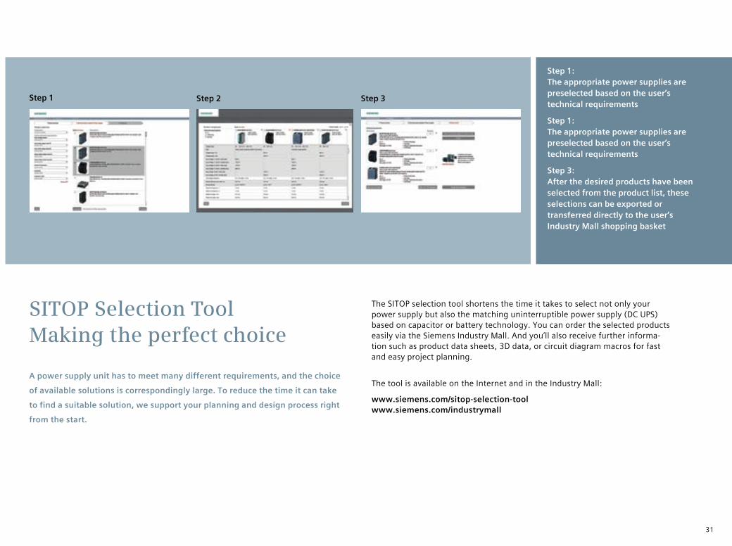
SITOP Selection Tool Making the perfect choice
Step 1: The appropriate power supplies are preselected based on the user’s technical requirements
Step 1: The appropriate power supplies are preselected based on the user’s technical requirements
Step 3: After the desired products have been selected from the product list, these selections can be exported or transferred directly to the user’s Industry Mall shopping basket
Step 1 Step 2 Step 3
The SITOP selection tool shortens the time it takes to select not only your power supply but also the matching uninterruptible power supply (DC UPS) based on capacitor or battery technology. You can order the selected products easily via the Siemens Industry Mall. And you’ll also receive further informa-tion such as product data sheets, 3D data, or circuit diagram macros for fast and easy project planning.
The tool is available on the Internet and in the Industry Mall:
www.siemens.com/sitop-selection-tool www.siemens.com/industrymall
Subject to change without prior notice Order No. E80001-A2650-P310-V3-7600Dispo 46305 GB 130526 MI.SC.ST.XXXX.52.3.01WS 09135.0 Printed in Germany © Siemens AG 2014
Siemens AG Industry Sector Industry Automation P.O. Box 48 48 90026 NUREMBERG GERMANY
The information provided in this brochure contains merely general descriptions or characteristics of performance which in actual case of use do not always apply as described or which may change as a result of further development of the products. An obligation to provide the respective characteristics shall only exist if expressly agreed in the terms of contract. All product designations may be trademarks or product names of Siemens AG or supplier companies whose use by third parties for their own purposes could violate the rights of the owners.
Industrial Security Siemens provides automation and drive products with indus- trial security functions that support the secure operation of plants or machines. They are an important component in a holistic industrial security concept. With this in mind, our products undergo continuous development. We therefore recommend that you keep yourself informed with respect to our product updates and that you use only the latest versions.Please find further information on this subject at: http://support.automation.siemens.com
You may also register for a product-specific newsletter at this address. To ensure the secure operation of a plant or machine it is also necessary to take suitable preventive action (e.g. cell protection concept) and to integrate the automation and drive compo-nents into a stateof- the-art holistic industrial security concept for the entire plant or machine. Any third-party products that may be in use must also be taken into account.Please find further information at:www.siemens.com/industrialsecurity
Further information More about SITOP:www.siemens.com/sitop
Information material for downloading:www.siemens.com/sitop-infomaterial
Easy selection of the suitable power supply unit with the SITOP selection tool:www.siemens.com/sitop-selection-tool
Manuals for downloading: www.siemens.com/sitop/manuals
CAx data (2D, 3D, circuit diagram macro) for downloading:www.siemens.com/sitop-cax
Compile all CAx data using the CAx online generator:www.siemens.com/cax
Order electronically over the Internet using the Industry Mall:www.siemens.com/industrymall
You can find your personal contact at:www.siemens.com/automation/partner