Embed Size (px)
Citation preview
Date: 2/21/04 Ingegneria dell'Automazione: Sistemi in Tempo Reale Giuseppe Lipari
Laurea Specialistica in Ingegneria dell'Automazione
Sistemi in Tempo RealeGiuseppe Lipari
Richiami di Architetture deiCalcolatori
Data: 24/02/2004 Ingegneria dell'Automazione: Sistemi in Tempo Reale Giuseppe Lipari
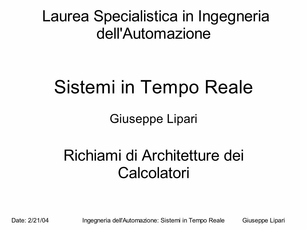
The HW/SW platform
● Let's start from the bottom: typical architecture of a micro-controller
CPU
Memory
InterruptController
Devices(A/D and D/A)
BusArbiter
DMAcontroller
Bus
Data: 24/02/2004 Ingegneria dell'Automazione: Sistemi in Tempo Reale Giuseppe Lipari
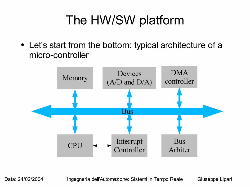
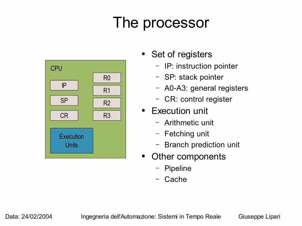
The processor
● Set of registers– IP: instruction pointer– SP: stack pointer– A0-A3: general registers– CR: control register
● Execution unit– Arithmetic unit– Fetching unit– Branch prediction unit
● Other components– Pipeline– Cache
CPU
IP
SP
R0
R1
R2
R3
ExecutionUnits
CR
Data: 24/02/2004 Ingegneria dell'Automazione: Sistemi in Tempo Reale Giuseppe Lipari
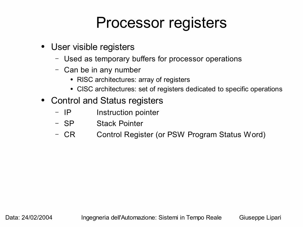
Processor registers● User visible registers
– Used as temporary buffers for processor operations– Can be in any number
● RISC architectures: array of registers● CISC architectures: set of registers dedicated to specific operations
● Control and Status registers– IP Instruction pointer– SP Stack Pointer– CR Control Register (or PSW Program Status Word)
Data: 24/02/2004 Ingegneria dell'Automazione: Sistemi in Tempo Reale Giuseppe Lipari
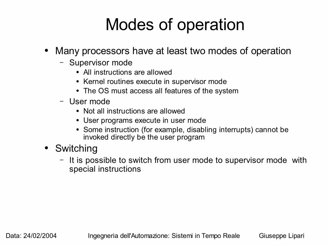
Modes of operation● Many processors have at least two modes of operation
– Supervisor mode● All instructions are allowed ● Kernel routines execute in supervisor mode● The OS must access all features of the system
– User mode● Not all instructions are allowed● User programs execute in user mode● Some instruction (for example, disabling interrupts) cannot be
invoked directly be the user program● Switching
– It is possible to switch from user mode to supervisor mode with special instructions
Data: 24/02/2004 Ingegneria dell'Automazione: Sistemi in Tempo Reale Giuseppe Lipari
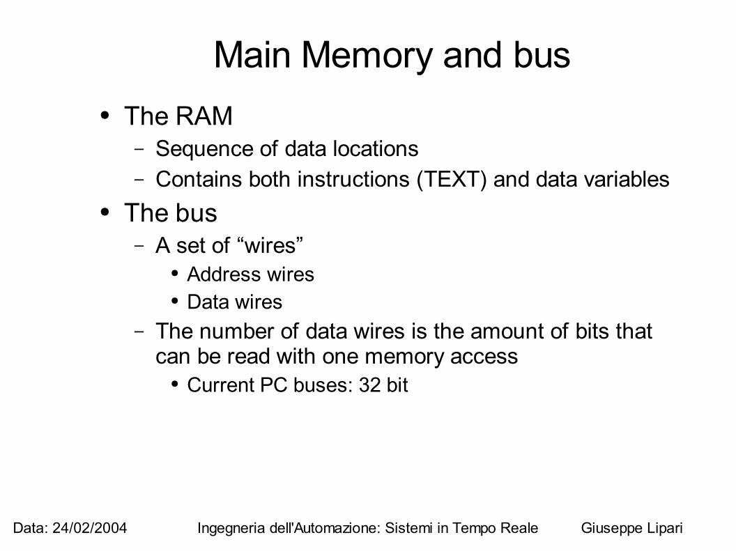
Main Memory and bus● The RAM
– Sequence of data locations– Contains both instructions (TEXT) and data variables
● The bus– A set of “wires”
● Address wires● Data wires
– The number of data wires is the amount of bits that can be read with one memory access
● Current PC buses: 32 bit
Data: 24/02/2004 Ingegneria dell'Automazione: Sistemi in Tempo Reale Giuseppe Lipari
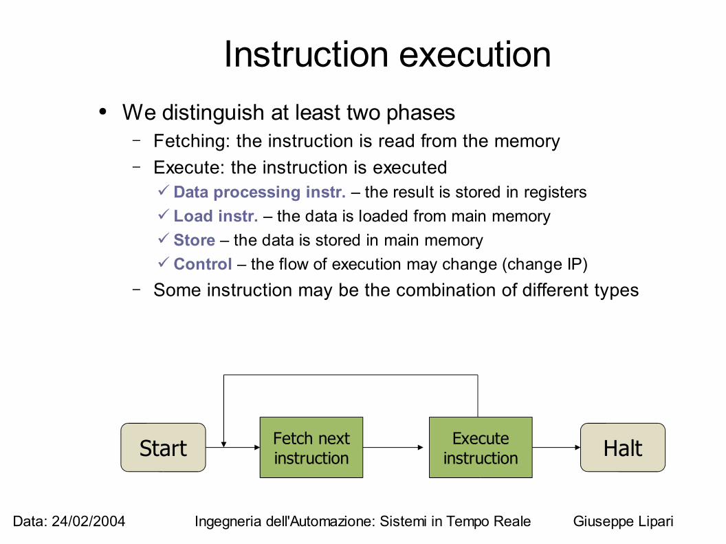
Instruction execution● We distinguish at least two phases
– Fetching: the instruction is read from the memory– Execute: the instruction is executed
Data processing instr. – the result is stored in registers Load instr. – the data is loaded from main memory Store – the data is stored in main memory Control – the flow of execution may change (change IP)
– Some instruction may be the combination of different types
Start HaltFetch nextinstruction
Executeinstruction
Data: 24/02/2004 Ingegneria dell'Automazione: Sistemi in Tempo Reale Giuseppe Lipari
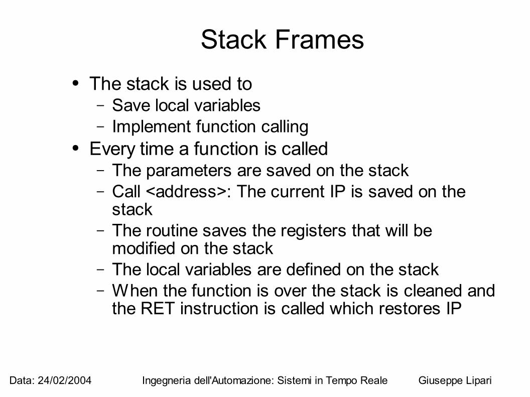
Stack Frames● The stack is used to
– Save local variables– Implement function calling
● Every time a function is called– The parameters are saved on the stack– Call <address>: The current IP is saved on the
stack– The routine saves the registers that will be
modified on the stack– The local variables are defined on the stack– When the function is over the stack is cleaned and
the RET instruction is called which restores IP
Data: 24/02/2004 Ingegneria dell'Automazione: Sistemi in Tempo Reale Giuseppe Lipari
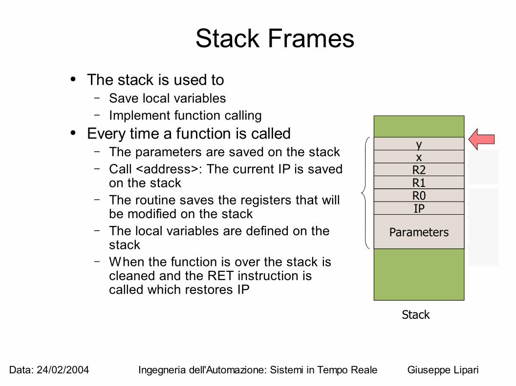
Stack Frames● The stack is used to
– Save local variables– Implement function calling
● Every time a function is called– The parameters are saved on the stack– Call <address>: The current IP is saved
on the stack– The routine saves the registers that will
be modified on the stack– The local variables are defined on the
stack– When the function is over the stack is
cleaned and the RET instruction is called which restores IP
Stack
Parameters
IPR0R1R2xy
Data: 24/02/2004 Ingegneria dell'Automazione: Sistemi in Tempo Reale Giuseppe Lipari
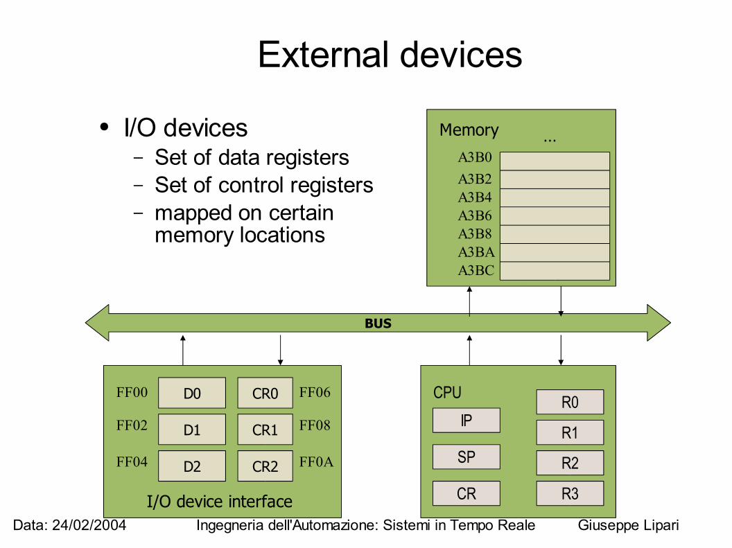
External devices
● I/O devices– Set of data registers – Set of control registers– mapped on certain
memory locations
D0 CR0
CR1
CR2
D1
D2
I/O device interface
BUS
CPUIP
SP
R0
R1
R2
R3CR
Memory
A3B0A3B2A3B4A3B6A3B8A3BAA3BC
…
FF00
FF02
FF04
FF06
FF08
FF0A
Data: 24/02/2004 Ingegneria dell'Automazione: Sistemi in Tempo Reale Giuseppe Lipari
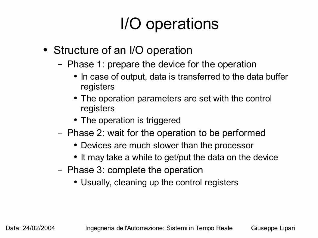
I/O operations● Structure of an I/O operation
– Phase 1: prepare the device for the operation● In case of output, data is transferred to the data buffer
registers● The operation parameters are set with the control
registers● The operation is triggered
– Phase 2: wait for the operation to be performed● Devices are much slower than the processor● It may take a while to get/put the data on the device
– Phase 3: complete the operation● Usually, cleaning up the control registers
Data: 24/02/2004 Ingegneria dell'Automazione: Sistemi in Tempo Reale Giuseppe Lipari
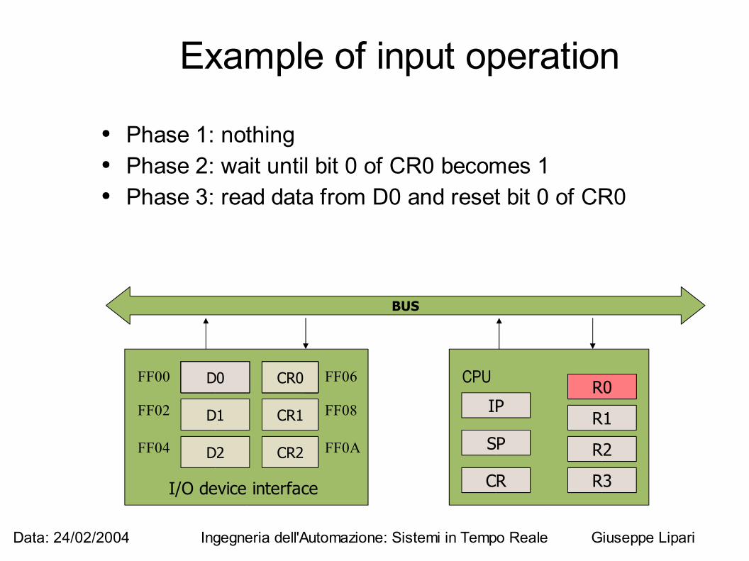
Example of input operation
● Phase 1: nothing● Phase 2: wait until bit 0 of CR0 becomes 1● Phase 3: read data from D0 and reset bit 0 of CR0
BUS
CPUIP
SP
R0
R1
R2
R3CR
D0 CR0
CR1
CR2
D1
D2
I/O device interface
FF00
FF02
FF04
FF06
FF08
FF0A
CR0D0 CR0D0 R0
Data: 24/02/2004 Ingegneria dell'Automazione: Sistemi in Tempo Reale Giuseppe Lipari
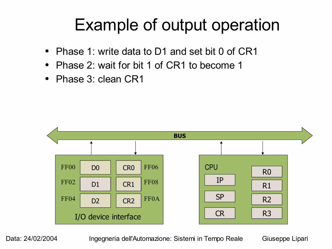
Example of output operation● Phase 1: write data to D1 and set bit 0 of CR1● Phase 2: wait for bit 1 of CR1 to become 1● Phase 3: clean CR1
BUS
CPUIP
SP
R0
R1
R2
R3CR
D0 CR0
CR1
CR2
D1
D2
I/O device interface
FF00
FF02
FF04
FF06
FF08
FF0A
CR1D1D1
R0
CR1
R0
CR1
Data: 24/02/2004 Ingegneria dell'Automazione: Sistemi in Tempo Reale Giuseppe Lipari
Temporal diagram● Polling
– This technique is called “polling” because the processor “polls” the device until the operation is completed
– In general, it can be a waste of time– The processor can executed something useful while
the device is working– How the processor can know when the device has
completed the I/O operation?
Data: 24/02/2004 Ingegneria dell'Automazione: Sistemi in Tempo Reale Giuseppe Lipari
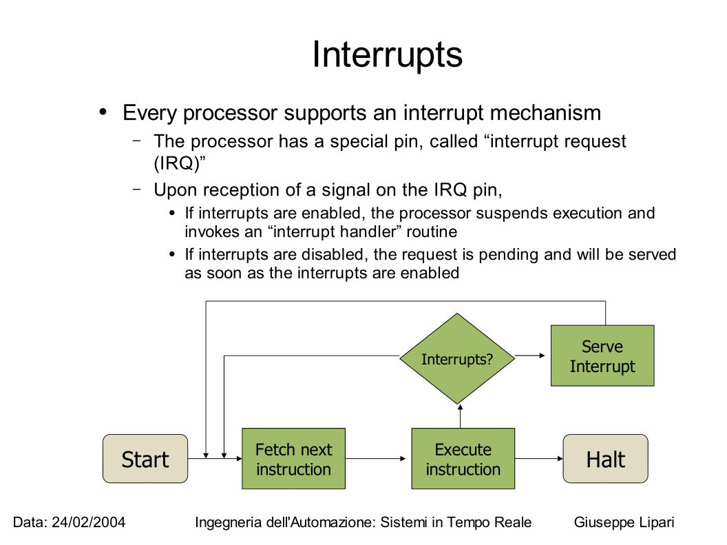
Interrupts● Every processor supports an interrupt mechanism
– The processor has a special pin, called “interrupt request (IRQ)”
– Upon reception of a signal on the IRQ pin, ● If interrupts are enabled, the processor suspends execution and
invokes an “interrupt handler” routine● If interrupts are disabled, the request is pending and will be served
as soon as the interrupts are enabled
Start HaltFetch nextinstruction
Executeinstruction
Interrupts?Serve
Interrupt
Data: 24/02/2004 Ingegneria dell'Automazione: Sistemi in Tempo Reale Giuseppe Lipari
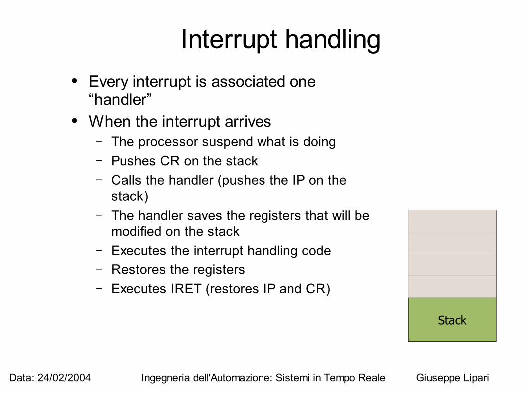
Interrupt handling● Every interrupt is associated one
“handler”● When the interrupt arrives
– The processor suspend what is doing– Pushes CR on the stack– Calls the handler (pushes the IP on the
stack)– The handler saves the registers that will be
modified on the stack– Executes the interrupt handling code– Restores the registers– Executes IRET (restores IP and CR)
Stack
CR
IP
R0
R1
Data: 24/02/2004 Ingegneria dell'Automazione: Sistemi in Tempo Reale Giuseppe Lipari
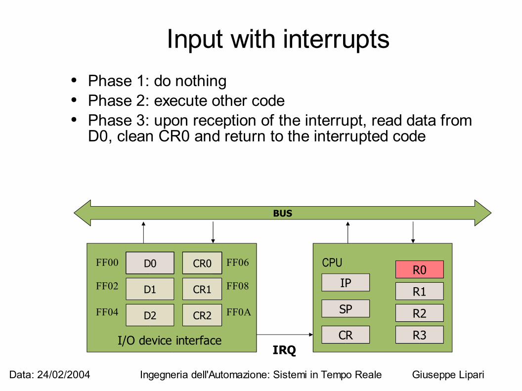
Input with interrupts● Phase 1: do nothing● Phase 2: execute other code● Phase 3: upon reception of the interrupt, read data from
D0, clean CR0 and return to the interrupted code
BUS
CPUIP
SP
R0
R1
R2
R3CR
D0 CR0
CR1
CR2
D1
D2
I/O device interface
FF00
FF02
FF04
FF06
FF08
FF0A
CR0D0 CR0D0 R0
IRQ
Data: 24/02/2004 Ingegneria dell'Automazione: Sistemi in Tempo Reale Giuseppe Lipari
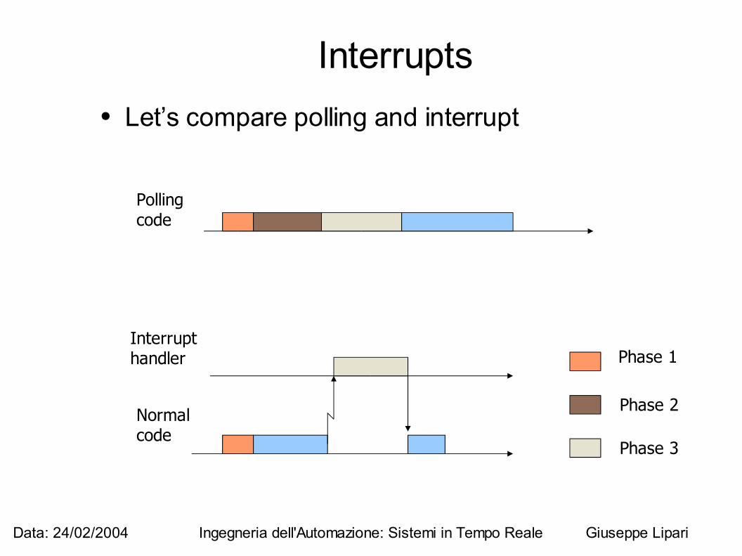
Interrupts● Let’s compare polling and interrupt
Normalcode
Interrupthandler Phase 1
Phase 2
Phase 3
Pollingcode
Data: 24/02/2004 Ingegneria dell'Automazione: Sistemi in Tempo Reale Giuseppe Lipari
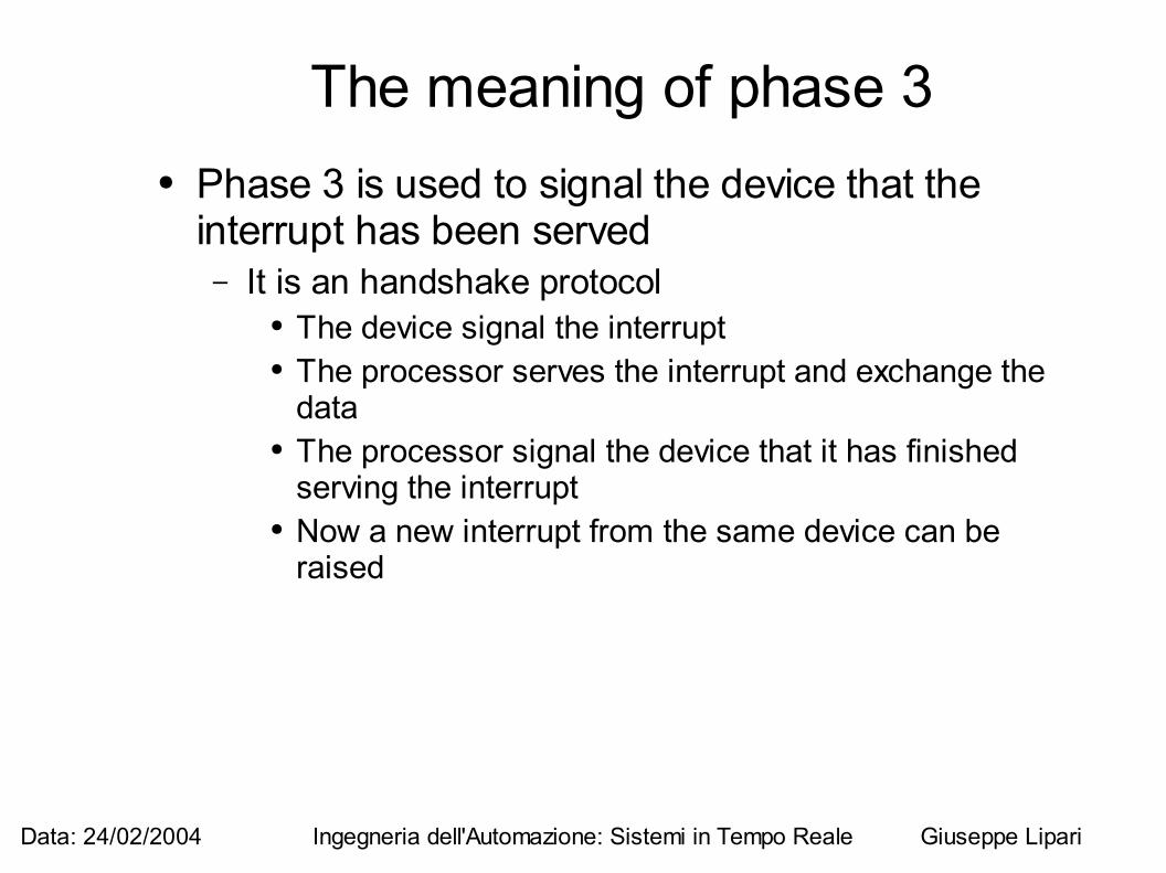
The meaning of phase 3● Phase 3 is used to signal the device that the
interrupt has been served– It is an handshake protocol
● The device signal the interrupt● The processor serves the interrupt and exchange the
data● The processor signal the device that it has finished
serving the interrupt● Now a new interrupt from the same device can be
raised
Data: 24/02/2004 Ingegneria dell'Automazione: Sistemi in Tempo Reale Giuseppe Lipari
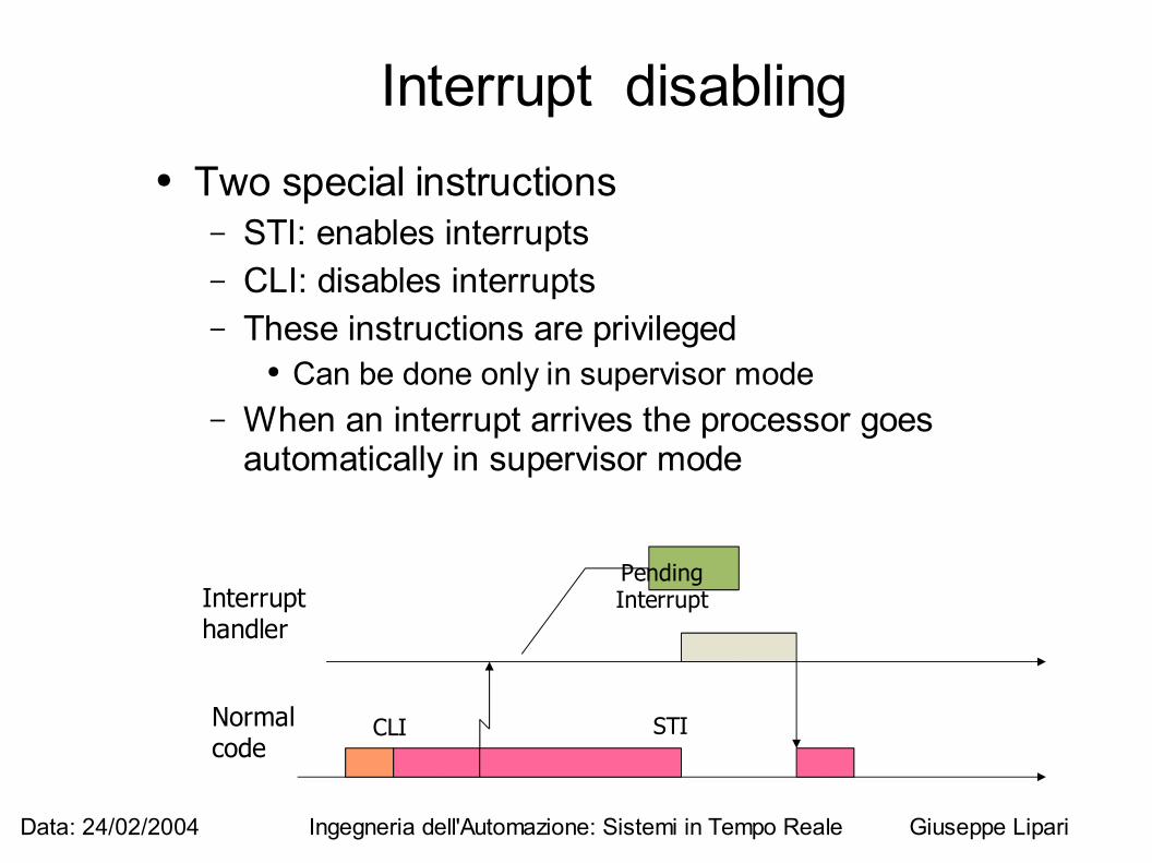
Interrupt disabling● Two special instructions
– STI: enables interrupts– CLI: disables interrupts– These instructions are privileged
● Can be done only in supervisor mode– When an interrupt arrives the processor goes
automatically in supervisor mode
Normalcode
Interrupthandler
CLI STI
PendingInterrupt
Data: 24/02/2004 Ingegneria dell'Automazione: Sistemi in Tempo Reale Giuseppe Lipari
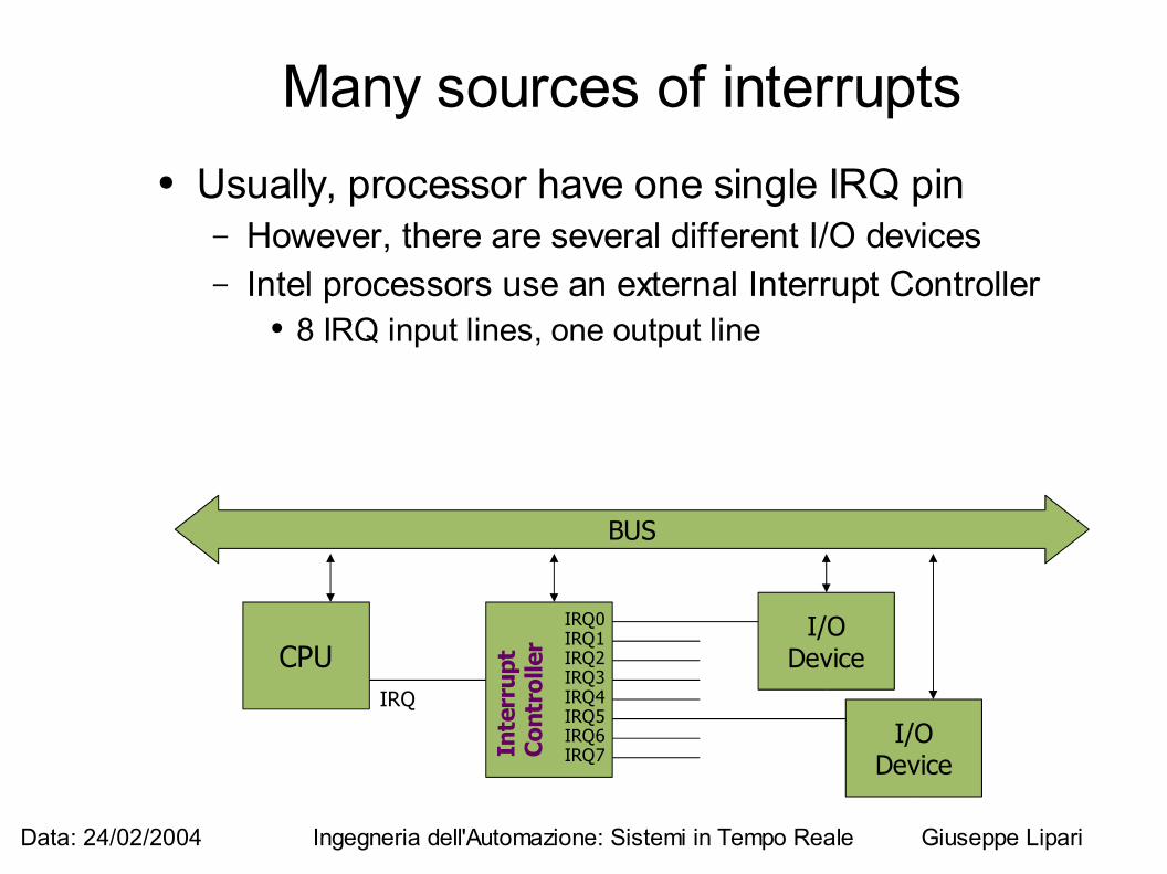
Many sources of interrupts● Usually, processor have one single IRQ pin
– However, there are several different I/O devices– Intel processors use an external Interrupt Controller
● 8 IRQ input lines, one output line
BUS
CPUIRQ
IRQ0IRQ1IRQ2IRQ3IRQ4IRQ5IRQ6IRQ7
I/ODevice
I/ODevice
Inte
rru p
t C
ont r
o lle
r
Data: 24/02/2004 Ingegneria dell'Automazione: Sistemi in Tempo Reale Giuseppe Lipari
Nesting interrupts● Interrupt disabling
– With CLI, all interrupts are disabled● When an interrupt is raised,
– before calling the interrupt handler, interrupts are automatically disabled
– However, it is possible to explicitely call STI to re-enable interrupts even during an interrupt handler
– In this way, we can “nest interrupts”● One interrupt handler can itself be interrupted by
another interrupt
Data: 24/02/2004 Ingegneria dell'Automazione: Sistemi in Tempo Reale Giuseppe Lipari
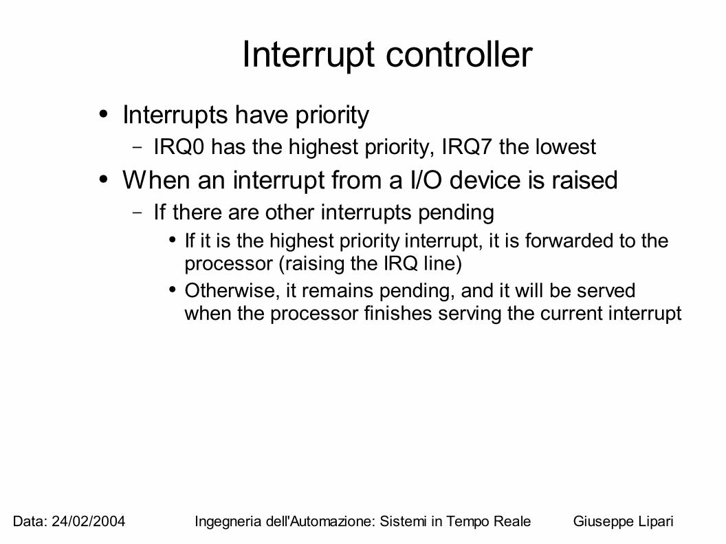
Interrupt controller● Interrupts have priority
– IRQ0 has the highest priority, IRQ7 the lowest● When an interrupt from a I/O device is raised
– If there are other interrupts pending● If it is the highest priority interrupt, it is forwarded to the
processor (raising the IRQ line)● Otherwise, it remains pending, and it will be served
when the processor finishes serving the current interrupt
Data: 24/02/2004 Ingegneria dell'Automazione: Sistemi in Tempo Reale Giuseppe Lipari
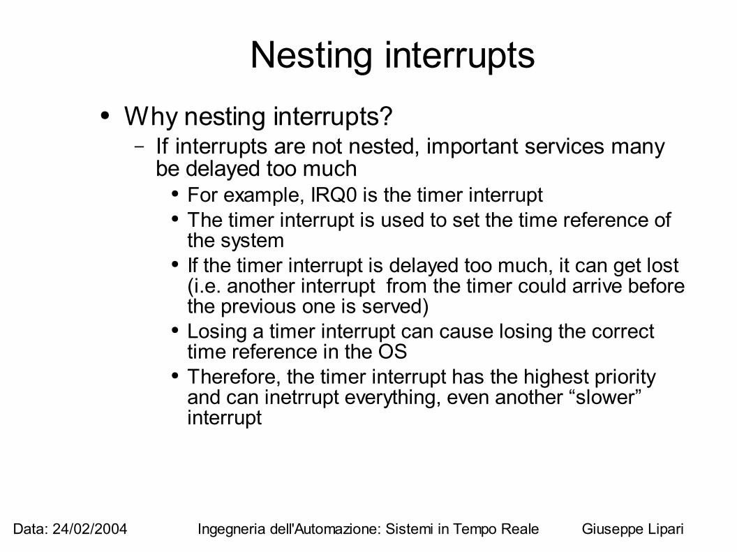
Nesting interrupts● Why nesting interrupts?
– If interrupts are not nested, important services many be delayed too much
● For example, IRQ0 is the timer interrupt● The timer interrupt is used to set the time reference of
the system● If the timer interrupt is delayed too much, it can get lost
(i.e. another interrupt from the timer could arrive before the previous one is served)
● Losing a timer interrupt can cause losing the correct time reference in the OS
● Therefore, the timer interrupt has the highest priority and can inetrrupt everything, even another “slower” interrupt
Data: 24/02/2004 Ingegneria dell'Automazione: Sistemi in Tempo Reale Giuseppe Lipari
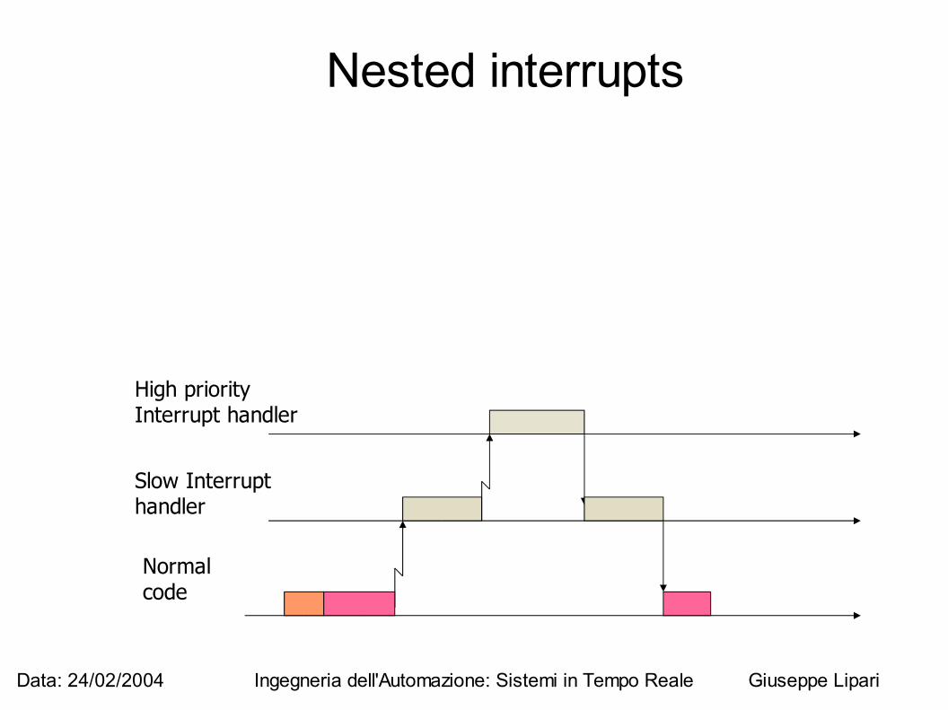
Nested interrupts
Normalcode
Slow Interrupthandler
High priority Interrupt handler
Data: 24/02/2004 Ingegneria dell'Automazione: Sistemi in Tempo Reale Giuseppe Lipari
Atomicity● An hardware instruction is atomic if it cannot be
“interleaved” with other instructions– Atomic operations are always sequentialized– Atomic operations cannot be interrupted
● They are safe operations● For example, transferring one word from memory to
register or viceversa– Non atomic operations can be interrupted
● They are not “safe” operations● Non elementary operations are not atomic
Data: 24/02/2004 Ingegneria dell'Automazione: Sistemi in Tempo Reale Giuseppe Lipari
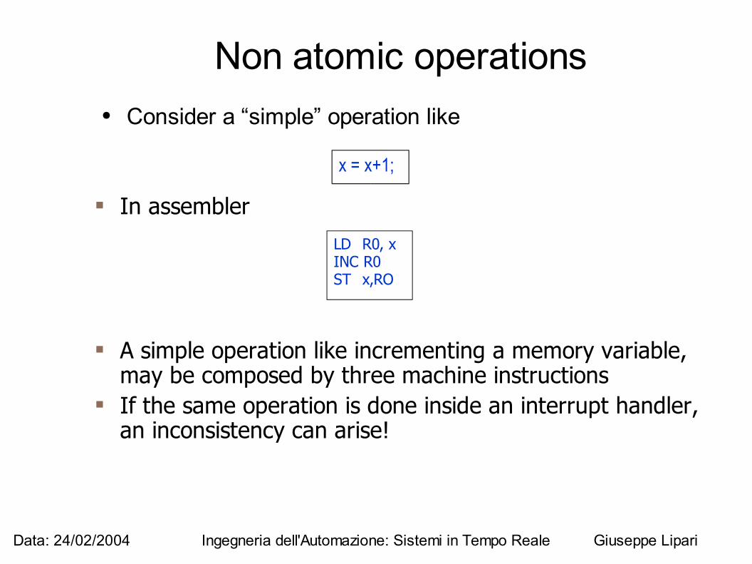
Non atomic operations● Consider a “simple” operation like
x = x+1;
In assembler LD R0, x
INC R0ST x,RO
A simple operation like incrementing a memory variable, may be composed by three machine instructions
If the same operation is done inside an interrupt handler, an inconsistency can arise!
Data: 24/02/2004 Ingegneria dell'Automazione: Sistemi in Tempo Reale Giuseppe Lipari
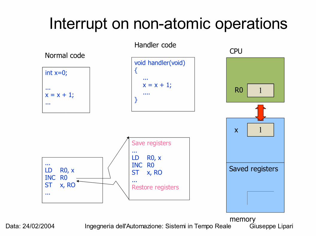
Interrupt on non-atomic operations
int x=0;
...x = x + 1;...
Normal codevoid handler(void){ ... x = x + 1; ....}
Handler code
...LD R0, xINC R0ST x, RO...
Save registers...LD R0, xINC R0ST x, RO...Restore registers
?R0
0x
CPU
memory
0
Saved registers
0
01
1
01
1
Data: 24/02/2004 Ingegneria dell'Automazione: Sistemi in Tempo Reale Giuseppe Lipari
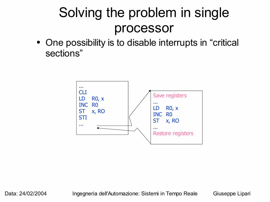
Solving the problem in single processor
● One possibility is to disable interrupts in “critical sections”
...CLILD R0, xINC R0ST x, ROSTI...
Save registers...LD R0, xINC R0ST x, RO...Restore registers
Data: 24/02/2004 Ingegneria dell'Automazione: Sistemi in Tempo Reale Giuseppe Lipari
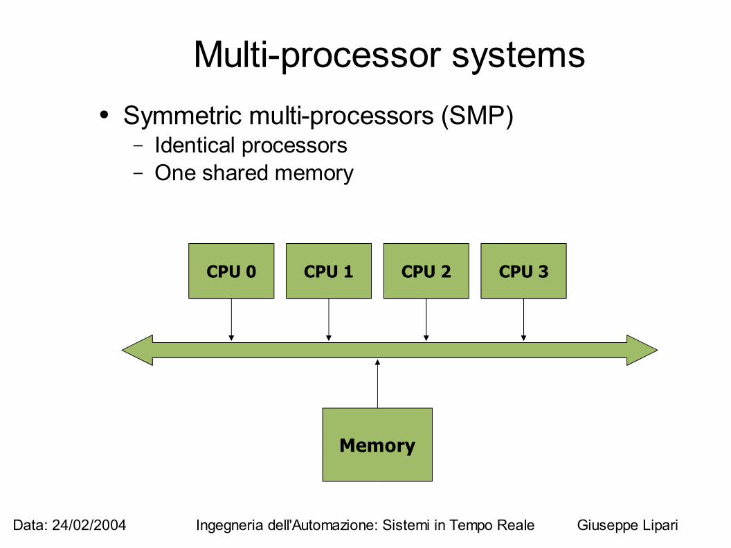
Multi-processor systems● Symmetric multi-processors (SMP)
– Identical processors– One shared memory
CPU 0 CPU 1 CPU 2 CPU 3
Memory
Data: 24/02/2004 Ingegneria dell'Automazione: Sistemi in Tempo Reale Giuseppe Lipari
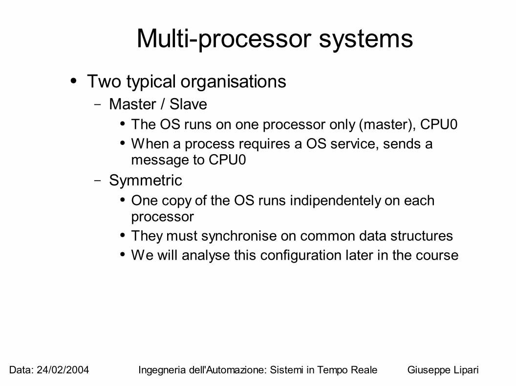
Multi-processor systems● Two typical organisations
– Master / Slave● The OS runs on one processor only (master), CPU0● When a process requires a OS service, sends a
message to CPU0– Symmetric
● One copy of the OS runs indipendentely on each processor
● They must synchronise on common data structures● We will analyse this configuration later in the course
Data: 24/02/2004 Ingegneria dell'Automazione: Sistemi in Tempo Reale Giuseppe Lipari
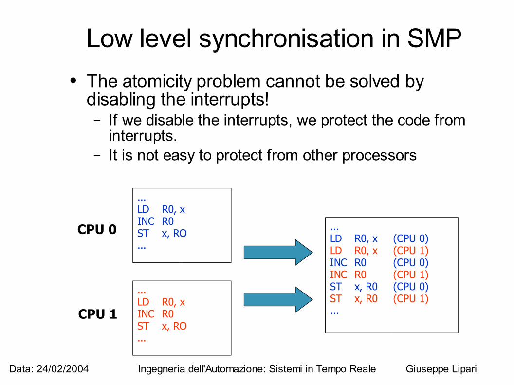
Low level synchronisation in SMP● The atomicity problem cannot be solved by
disabling the interrupts!– If we disable the interrupts, we protect the code from
interrupts. – It is not easy to protect from other processors
...LD R0, xINC R0ST x, RO...
...LD R0, xINC R0ST x, RO...
...LD R0, x (CPU 0)LD R0, x (CPU 1)INC R0 (CPU 0)INC R0 (CPU 1)ST x, R0 (CPU 0)ST x, R0 (CPU 1)...
CPU 0
CPU 1
Data: 24/02/2004 Ingegneria dell'Automazione: Sistemi in Tempo Reale Giuseppe Lipari
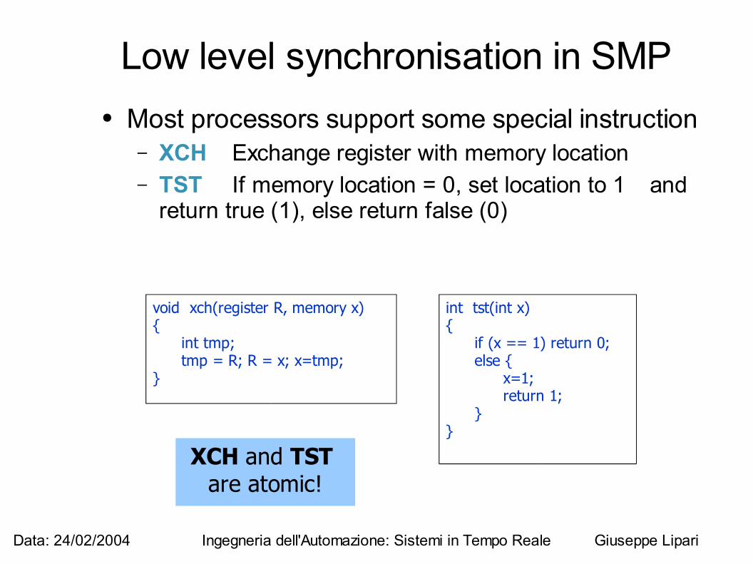
XCH and TST are atomic!
Low level synchronisation in SMP ● Most processors support some special instruction
– XCH Exchange register with memory location– TST If memory location = 0, set location to 1 and
return true (1), else return false (0)
void xch(register R, memory x){
int tmp;tmp = R; R = x; x=tmp;
}
int tst(int x){
if (x == 1) return 0;else {
x=1;return 1;
}}
Data: 24/02/2004 Ingegneria dell'Automazione: Sistemi in Tempo Reale Giuseppe Lipari
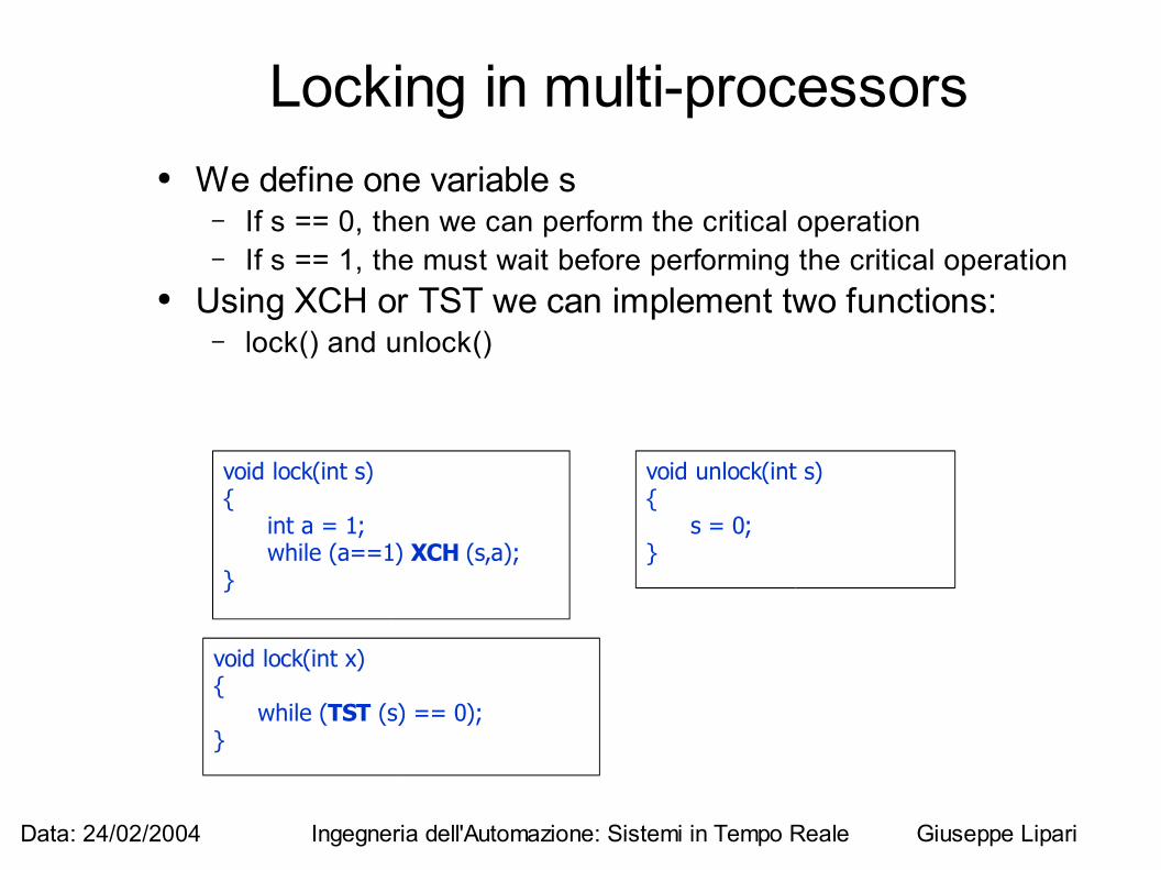
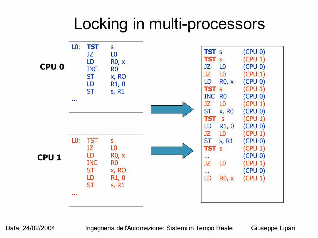
Locking in multi-processors● We define one variable s
– If s == 0, then we can perform the critical operation– If s == 1, the must wait before performing the critical operation
● Using XCH or TST we can implement two functions:– lock() and unlock()
void lock(int s){
int a = 1;while (a==1) XCH (s,a);
}
void lock(int x){
while (TST (s) == 0);}
void unlock(int s){
s = 0;}
Data: 24/02/2004 Ingegneria dell'Automazione: Sistemi in Tempo Reale Giuseppe Lipari
Locking in multi-processorsL0: TST s
JZ L0LD R0, xINC R0ST x, ROLD R1, 0ST s, R1
...
TST s (CPU 0)TST s (CPU 1)JZ L0 (CPU 0)JZ L0 (CPU 1)LD R0, x (CPU 0)TST s (CPU 1)INC R0 (CPU 0)JZ L0 (CPU 1)ST x, R0 (CPU 0)TST s (CPU 1)LD R1, 0 (CPU 0)JZ L0 (CPU 1)ST s, R1 (CPU 0)TST s (CPU 1)... (CPU 0)JZ L0 (CPU 1)... (CPU 0)LD R0, x (CPU 1)
CPU 0
CPU 1
L0: TST sJZ L0LD R0, xINC R0ST x, ROLD R1, 0ST s, R1
...
Data: 24/02/2004 Ingegneria dell'Automazione: Sistemi in Tempo Reale Giuseppe Lipari
Locking● The lock / unlock operations are “safe”
– No matter how you interleave the operations, there is no possibility that the “critical parts interleave
– However, lock() is an active wait and a possible wast of time
● The problem of locking is very general and will be analysed and solved in greater details later