Embed Size (px)
Citation preview

RelaysSIRIUS 3RR24 Monitoring Relays for Mounting onto 3RT2 Contactors for IO-Link
Current and active current monitoring
10/80 Siemens IC 10 · 2014
10
■ Benefits
• Can be mounted directly on 3RT2 contactors and 3RA23 reversing contactor assemblies, in other words, there is no need for additional wiring in the main circuit
• Optimally coordinated with the technical characteristics of the 3RT2 contactors
• No separate current transformer required• Variably adjustable to overshoot, undershoot or range
monitoring• Freely configurable delay times and RESET response• Display of ACTUAL value and status messages• All versions with removable control current terminals• All versions with screw or spring-type terminals• Simple determination of the threshold values through direct
reference to actually measured values for setpoint loading• Range monitoring and selectable active current measurement
mean that only one device for monitoring a motor is required along the entire torque curve
• In addition to current monitoring it is also possible to monitor for current unbalance, broken cables, phase failure, phase sequence, residual current and motor blocking.
• Integrated counter for operating cycles and operating hours to support requirements-based maintenance of the monitored machine or application
• Simple cyclical transmission of the current measured values, relay switching states and events to a controller
• Remote parameterization• Automatic reparameterizing when devices are exchanged• Simple duplication of identical or similar parameterizations• Reduction of control current wiring• Elimination of testing costs and wiring errors• Reduction of configuration work• Integration in TIA means clear diagnostics if a fault occurs• Cost saving and space saving in control cabinet due to the
elimination of AI and IO modules as well as analog signal converters and duplicated sensors
■ Application
• Monitoring of current overshoot and undershoot• Monitoring of broken conductors• Monitoring of no-load operation and load shedding, e.g. in the
event of a torn V-belt or no-load operation of a pump• Monitoring of overload, e.g. on pumps due to a dirty filter
system• Monitoring the functionality of electrical loads such as heaters• Monitoring of wrong phase sequence on mobile equipment
such as compressors or cranes• Monitoring of high-impedance faults to ground, e.g. caused
by damaged insulation or moisture
The use of SIRIUS monitoring relays for IO-Link is particularly recommended for machines and plant in which these relays, in addition to their monitoring function, are to be connected to the automation level for the rapid, simple and fault-free provision of the current measured values and/or for remote parameterization.
The monitoring relays can either relieve the controller of monitor-ing tasks or, as a second monitoring entity in parallel to and in-dependent of the controller, increase the reliability in the process or in the system. In addition, the elimination of AI and IO modules allows the width of the controller to be reduced despite signifi-cantly expanded functionality.
SIRIUS_IC10_chap10_English_2014.book Seite 80 Freitag, 10. Januar 2014 12:08 12
© Siemens AG 2013

RelaysSIRIUS 3RR24 Monitoring Relays for Mounting onto 3RT2 Contactors for IO-Link
10/81Siemens IC 10 · 2014
Current and active current monitoring
10
■ Technical specifications
Function charts of 3RR24 for IO-Link, digitally adjustable
With the closed-circuit principle selected upon application of the control supply voltage
Current overshoot
Current undershoot with residual current monitoring
Range monitoring
Phase sequence monitoring
Circuit diagrams
Hysteresis
onDel onDel ▲Del RsDel RsDel
QonQoff
n x ▲
L+/L-
▲, !▲
31/3431/32
>n x >
3~ = 0IC
01_0
0185
QonQoff
Hysteresis
L+/L-
▼, !▼
31/3431/32
onDel onDel ▼Del RsDel
3~ = 0
> 1+ 2+ 3 ≥
IC01
_001
87
QonQoff
Hysteresis
Hyst.
31/3431/32
onDel onDel ▲Del ▼DelRsDel RsDel
IC01
_001
86
L+/L-
▲, !▲
▼, !▼
3~ = 0
> < 1,2 ~ = 0
QonQoff
3~ = 0
IC01
_001
88
L+/L-
31/34
L3-L2-L1
31/32
3RR2441-1AA40 3RR2441-2AA40, 3RR2442-.AA40
Note:It is not necessary to protect the measuring circuit for device protection. The protective device for line protection depends on the cross-section used.
IC01_00189
IO-Link
326T34T22T1
31L-C/QL+
34 A214/22IC01_00190
326T34T22T1
31L-C/QL+
34
IO-Link
SIRIUS_IC10_chap10_English_2014.book Seite 81 Freitag, 10. Januar 2014 12:08 12
© Siemens AG 2013

RelaysSIRIUS 3RR24 Monitoring Relays for Mounting onto 3RT2 Contactors for IO-Link
Current and active current monitoring
10/82 Siemens IC 10 · 2014* You can order this quantity or a multiple thereof.
Illustrations are approximate
10
■ Selection and ordering data
SIRIUS 3RR24 current monitoring relays for IO-Link• For load monitoring of motors or other loads• Multi-phase monitoring of undercurrent and overcurrent• Starting and tripping delay can be adjusted separately• Tripping delay 0 to 999.9 s• Auto or Manual RESET
PU (UNIT, SET, M) = 1PS* = 1 unitPG = 41H
Notes:
Devices required for the communication via IO-Link:• Any controller that supports the IO-Link (e.g. ET 200S with
CPU or S7-300 plus ET 200S distributed I/O), see Catalog ST 70 "SIMATIC Products for Totally Integrated Automation"
• IO-Link master (IO-Link master 4SI IO-Link or 4SI SIRIUS interface module, which can connect all SIRIUS IO-Link devices to a controller, see Chapter 2 "Industrial Communication")
Each monitoring relay requires an IO-Link channel.
Size Measuring range Hysteresis Control supply voltage Us DT Screw terminals DT Spring-type terminals
A A VArticle No. Price
per PUArticle No. Price
per PU
Digitally adjustable, LCD, open-circuit or closed-circuit principle, 1 CO, 1 semiconductor output (in SIO mode), 3-phase current monitoring, active current or apparent current monitoring, current unbalance monitoring, phase sequence monitoring, residual current monitoring, blocking current monitoring, operating hours counter, operating cycles counter, reclosing delay time 0 ... 999.9 min, start-up delay 0 ... 999.9 s, separate settings for warning and alarm thresholds
S00 1.6 ... 16 0.1 ... 3 24 DC A 3RR2441-1AA40 A 3RR2441-2AA40
S0 4 ... 40 0.1 ... 8 24 DC A 3RR2442-1AA40 A 3RR2442-2AA40
3RR2441-1AA40 3RR2442-1AA40 3RR2441-2AA40 3RR2442-2AA40
SIRIUS_IC10_chap10_English_2014.book Seite 82 Freitag, 10. Januar 2014 12:08 12
© Siemens AG 2013

RelaysSIRIUS 3RR24 Monitoring Relays for Mounting onto 3RT2 Contactors for IO-Link
Current and active current monitoring
10/83Siemens IC 10 · 2014* You can order this quantity or a multiple thereof.Illustrations are approximate
10
■ Accessories
1) The accessories are identical to those of the 3RU21 thermal overload relays and the 3RB3 solid-state overload relays see Chapter 7 "Protection Equipment".
2) PC labeling system for individual inscriptionof unit labeling plates available from:murrplastik Systemtechnik GmbHsee Chapter 16, "Appendix" ➞ "External Partners".
Use Version Size DT Article No. Priceper PU
PU(UNIT,
SET, M)
PS* PG
Terminal supports for stand-alone installation1)
3RU2916-3AA01
For 3RR24 For separate mounting of the overload relays or monitoring relays; screw and snap-on mounting onto TH 35 standard mounting rail according to IEC 60715
Screw terminals
• Screw connection S00 } 3RU2916-3AA01 1 1 unit 41F
S0 } 3RU2926-3AA01 1 1 unit 41F
3RU2926-3AC01
Spring-type terminals
• Spring-type connection S00 B 3RU2916-3AC01 1 1 unit 41FS0 B 3RU2926-3AC01 1 1 unit 41F
Blank labels
3RT2900-1SB20
For 3RR24 Unit labeling plates2)
For SIRIUS devices
20 mm x 7 mm, titanium gray D 3RT2900-1SB20 100 340 units 41B
Sealable covers
3RR2940
For 3RR24 Sealable coversFor securing against unintentional or unauthorized adjustment of settings
A 3RR2940 1 5 units 41H
Tools for opening spring-type terminals
3RA2908-1A
For auxiliary circuit connections
Screwdrivers For all SIRIUS devices with spring-type terminals 3.0 mm x 0.5 mm, length approx. 200 mm, titanium gray/black, partially insulated
Spring-type terminals
A 3RA2908-1A 1 1 unit 41B
IC01
_001
81
SIRIUS_IC10_chap10_English_2014.book Seite 83 Freitag, 10. Januar 2014 12:08 12
© Siemens AG 2013
RelaysSIRIUS 3UG45, 3UG46 Monitoring Relays for Stand-Alone Installation
General data
10/84 Siemens IC 10 · 2014
10
■ Overview
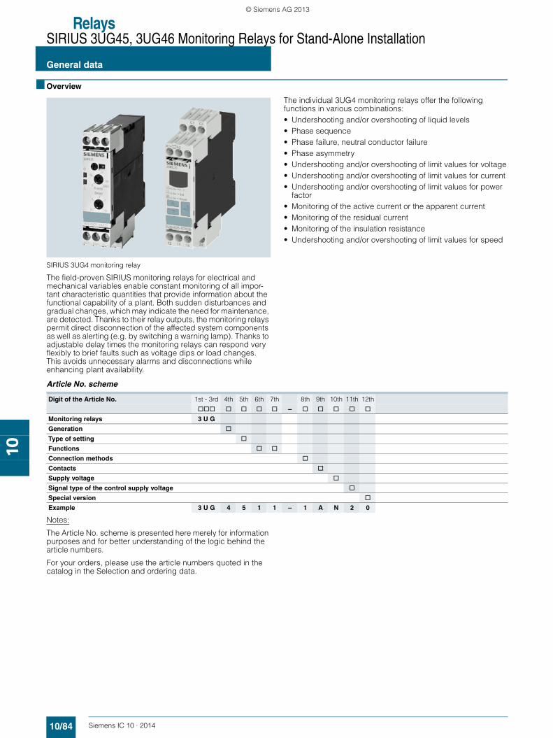
SIRIUS 3UG4 monitoring relay
The field-proven SIRIUS monitoring relays for electrical and mechanical variables enable constant monitoring of all impor-tant characteristic quantities that provide information about the functional capability of a plant. Both sudden disturbances and gradual changes, which may indicate the need for maintenance, are detected. Thanks to their relay outputs, the monitoring relays permit direct disconnection of the affected system components as well as alerting (e.g. by switching a warning lamp). Thanks to adjustable delay times the monitoring relays can respond very flexibly to brief faults such as voltage dips or load changes. This avoids unnecessary alarms and disconnections while enhancing plant availability.
The individual 3UG4 monitoring relays offer the following functions in various combinations:• Undershooting and/or overshooting of liquid levels• Phase sequence• Phase failure, neutral conductor failure• Phase asymmetry• Undershooting and/or overshooting of limit values for voltage• Undershooting and/or overshooting of limit values for current• Undershooting and/or overshooting of limit values for power
factor• Monitoring of the active current or the apparent current• Monitoring of the residual current• Monitoring of the insulation resistance• Undershooting and/or overshooting of limit values for speed
Article No. scheme
Notes:
The Article No. scheme is presented here merely for information purposes and for better understanding of the logic behind the article numbers.
For your orders, please use the article numbers quoted in the catalog in the Selection and ordering data.
Digit of the Article No. 1st - 3rd 4th 5th 6th 7th 8th 9th 10th 11th 12th
@@@ @ @ @ @ – @ @ @ @ @
Monitoring relays 3 U G
Generation @
Type of setting @
Functions @ @
Connection methods @
Contacts @
Supply voltage @
Signal type of the control supply voltage @
Special version @
Example 3 U G 4 5 1 1 – 1 A N 2 0
SIRIUS_IC10_chap10_English_2014.book Seite 84 Freitag, 10. Januar 2014 12:08 12
© Siemens AG 2013

RelaysSIRIUS 3UG45, 3UG46 Monitoring Relays for Stand-Alone Installation
10/85Siemens IC 10 · 2014
General data
10
■ Benefits
• Customary screw and spring-type terminals for quick and reliable wiring
• Fast commissioning thanks to menu-guided parameterization and actual value display for limit value determination
• Reduced space requirement in the control cabinet thanks to a consistent width of 22.5 mm
• Parameterizable monitoring functions, delay times, reset response, etc.
• Reduced stockkeeping thanks to minimized variance and large measuring ranges
• Wide-voltage power supply units for global applicability• Device replacement without renewed wiring thanks to
removable terminals• Reliable system diagnostics thanks to actual value display
and connectable fault memory• Rapid diagnostics thanks to unambiguous error messages on
the display
Advantages through energy efficiency
Overview of the energy management process
We offer you a unique portfolio for industrial energy manage-ment, using an energy management system that helps to opti-mally define your energy needs. We split up our industrial energy management into three phases – identify, evaluate, and realize – and we support you with the appropriate hardware and software solutions in every process phase.
The innovative SIRIUS industrial controls products can also make a major contribution to the energy efficiency of a plant (www.siemens.com/sirius/energysaving).
The 3UG4 monitoring relays contribute to energy efficiency throughout the plant as follows:• Shutdown in the event of no-load operation
(e.g. pump no-load operation)• Reactive-power compensation by means of power factor
monitoring• Load shedding of predefined loads in the event of current
overshoots
■ Application
The SIRIUS 3UG4 monitoring relays monitor the most diverse electrical and mechanical quantities in the feeder, and provide reliable protection against damage in the plant. For this purpose, they offer freely parameterizable limit values and diverse options for adapting to the respective task, and in the event of a fault, they provide clear diagnostics information.
The digitally adjustable products also display the current mea-sured values direct on the device. This not only facilitates the display of valuable plant status information during operation, it also enables adjustment of the monitored limit values in accor-dance with the actual conditions.
The positive result: More selective avoidance of production faults – sustained increases in availability and productivity.
The 3UG4 monitoring relays are available for the following applications:• Line and single-phase voltage monitoring• Single-phase current monitoring or power factor and
active current monitoring• Residual current monitoring• Insulation monitoring• Level monitoring• Speed monitoring
IC01
_002
44
SIRIUS_IC10_chap10_English_2014.book Seite 85 Freitag, 10. Januar 2014 12:08 12
© Siemens AG 2013
RelaysSIRIUS 3UG45, 3UG46 Monitoring Relays for Stand-Alone Installation
General data
10/86 Siemens IC 10 · 2014
10
■ Technical specifications
■ More information
Manual "3UG45/3UG46 and 3RR21/3RR22 Monitoring Relays" see http://support.automation.siemens.com/WW/view/en/54397927.
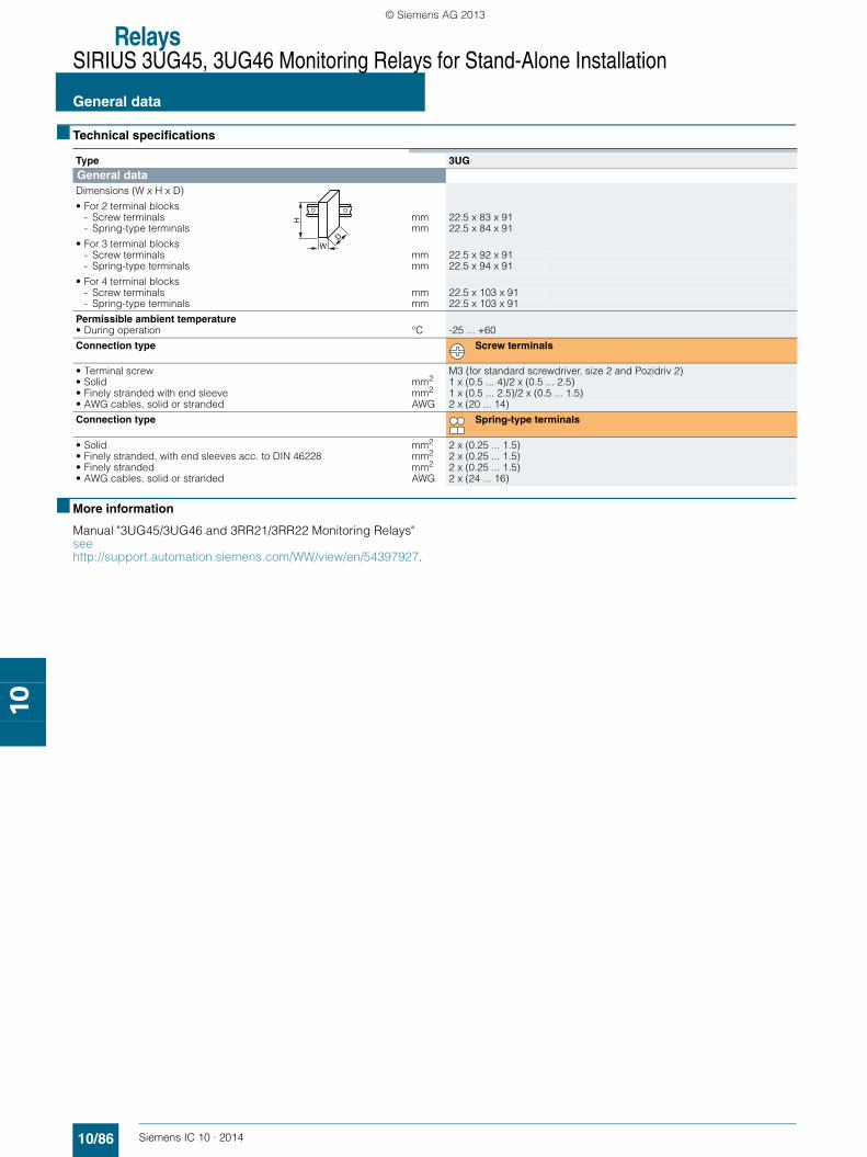
Type 3UGGeneral dataDimensions (W x H x D)
• For 2 terminal blocks- Screw terminals mm 22.5 x 83 x 91- Spring-type terminals mm 22.5 x 84 x 91
• For 3 terminal blocks- Screw terminals mm 22.5 x 92 x 91- Spring-type terminals mm 22.5 x 94 x 91
• For 4 terminal blocks- Screw terminals mm 22.5 x 103 x 91- Spring-type terminals mm 22.5 x 103 x 91
Permissible ambient temperature• During operation °C -25 ... +60
Connection type Screw terminals
• Terminal screw M3 (for standard screwdriver, size 2 and Pozidriv 2)• Solid mm2 1 x (0.5 ... 4)/2 x (0.5 ... 2.5)• Finely stranded with end sleeve mm2 1 x (0.5 ... 2.5)/2 x (0.5 ... 1.5)• AWG cables, solid or stranded AWG 2 x (20 ... 14)
Connection type Spring-type terminals
• Solid mm2 2 x (0.25 ... 1.5)• Finely stranded, with end sleeves acc. to DIN 46228 mm2 2 x (0.25 ... 1.5)• Finely stranded mm2 2 x (0.25 ... 1.5)• AWG cables, solid or stranded AWG 2 x (24 ... 16)
W
H
D
SIRIUS_IC10_chap10_English_2014.book Seite 86 Freitag, 10. Januar 2014 12:08 12
© Siemens AG 2013

RelaysSIRIUS 3UG45, 3UG46 Monitoring Relays for Stand-Alone Installation
10/87Siemens IC 10 · 2014
Line monitoring
10
■ Overview
SIRIUS 3UG4615 monitoring relay
Solid-state line monitoring relays provide maximum protection for mobile machines and plants or for unstable networks. Network and voltage faults can thus be detected early and rectified before far greater damage ensues.
Depending on the version, the relays monitor phase sequence, phase failure with and without N conductor monitoring, phase asymmetry, undervoltage or overvoltage.
Phase asymmetry is evaluated as the difference between the greatest and the smallest phase voltage relative to the greatest phase voltage. Undervoltage or overvoltage exists when at least one phase voltage deviates by 20 % from the set rated system voltage or the directly set limit values are overshot or undershot. The rms value of the voltage is measured.
With the 3UG4617 or 3UG4618 relay, a wrong direction of rotation can also be corrected automatically.
■ Benefits
• Can be used without auxiliary voltage in any network from 160 to 630 V AC worldwide thanks to wide voltage range
• Variably adjustable to overshoot, undershoot or range monitoring
• Freely configurable delay times and RESET response• Width 22.5 mm• Permanent display of ACTUAL value and network fault type
on the digital versions• Automatic correction of the direction of rotation by distinguish-
ing between power system faults and wrong phase sequence• All versions with removable terminals• All versions with screw or spring-type terminals
■ Application
The relays are used above all for mobile equipment, e.g. air conditioning compressors, refrigerating containers, building site compressors and cranes.
■ Technical specifications
3UG4511 monitoring relays
The 3UG4511 phase sequenced relay monitors the phase sequence in a three-phase network. No adjustments are required for operation. The device has an internal power supply and works using the closed-circuit principle. If the phase sequence at the terminals L1-L2-L3 is correct, the output relay picks up after the delay time has elapsed and the LED is lit. If the phase sequence is wrong, the output relay remains in its rest position.
Note:
When one phase fails, connected loads (motor windings, lamps, transformers, coils, etc.) create a feedback voltage at the termi-nal of the failed phase due to the network coupling. Because the 3UG4511 relays are not resistant to voltage feedback, such a phase failure is not detected. Should this be required, then the 3UG4512 monitoring relay must be used.
Correct phase sequence
Wrong phase sequence
Function Application
Phase sequence • Direction of rotation of the drive
Phase failure • A fuse has tripped
• Failure of the control supply voltage
• Broken cable
Phase asymmetry • Overheating of the motor due to asymmetrical voltage
• Detection of asymmetrically loaded networks
Undervoltage • Increased current on a motor with corresponding overheating
• Unintentional resetting of a device
• Network collapse, particularly with battery power
Overvoltage • Protection of a plant against destruction due to overvoltage
NS
B0_
0156
5a
11/14
L1-L2-L3
11/12
21/2421/22
ON
NS
B0_
0156
6a
11/14
L3-L2-L1
11/12
21/2421/22
OFF
SIRIUS_IC10_chap10_English_2014.book Seite 87 Freitag, 10. Januar 2014 12:08 12
© Siemens AG 2013

RelaysSIRIUS 3UG45, 3UG46 Monitoring Relays for Stand-Alone Installation
Line monitoring
10/88 Siemens IC 10 · 2014
10
3UG4512 monitoring relays
The 3UG4512 line monitoring relay monitors three-phase networks with regard to phase sequence, phase failure and phase unbalance of 10 %. Thanks to a special measuring method, a phase failure is reliably detected in spite of the wide voltage range from 160 to 690 V and feedback through the load of up to 90 %. The device has an internal power supply and works using the closed-circuit principle. No adjustments are required. When the mains voltage is switched on, the green LED is lit. If the phase sequence at the terminals L1-L2-L3 is correct, the output relay picks up. If the phase sequence is wrong, the red LED flashes and the output relay remains in its rest position. If a phase fails, the red LED is permanently lit and the output relay drops.
Note:
The red LED is a fault diagnostic indicator and does not show the current relay status. The 3UG4512 monitoring relay is suitable for line frequencies of 50/60 Hz.
Phase failure
Wrong phase sequence
3UG4513 monitoring relays
The 3UG4513 line monitoring relay monitors three-phase networks with regard to phase sequence, phase failure, phase asymmetry and undervoltage of 20 %. The device has an inter-nal power supply and works using the closed-circuit principle. The hysteresis is 5 %. The integrated response delay time is adjustable from 0 to 20 s and responds to undervoltage. If the direction is incorrect, the device switches off immediately. Thanks to a special measuring method, a phase failure is reliably detected in spite of the wide voltage range from 160 to 690 V and feedback through the load of up to 80 %. When the mains voltage is switched on, the green LED is lit. If the phase se-quence at the terminals L1-L2-L3 is correct, the output relay picks up. If the phase sequence is wrong, the red LED flashes and the output relay remains in its rest position. If a phase fails, the red LED is permanently lit and the output relay drops.
Note:
The red LED is a fault diagnostic indicator and does not show the current relay status. The 3UG4513 monitoring relay is suitable for line frequencies of 50/60 Hz.
Phase failure and undervoltage
Wrong phase sequence
NS
B0_
0156
7a
11/14
L1-L2-L3L2-L3L1-L2-L3
11/12
21/2421/22
OFF OFFONPhase failure
LED rd
NS
B0_
0156
8a
11/1411/12
21/2421/22
L3-L2-L1
FLASHPhase sequence
OFFOFF
LED rd
11/14
-20 %L1-L2-L3L2-L3L1-L2-L3
n3~5 %
11/12
21/2421/22
DelayOFFOFF OFFON
Phase failureON
LED rd
Hysteresis
NSB0_01569b
NS
B0_
0157
0a
11/1411/12
21/2421/22
L3-L2-L1
FLASHPhase sequence
OFFOFF
LED rd
SIRIUS_IC10_chap10_English_2014.book Seite 88 Freitag, 10. Januar 2014 12:08 12
© Siemens AG 2013
RelaysSIRIUS 3UG45, 3UG46 Monitoring Relays for Stand-Alone Installation
10/89Siemens IC 10 · 2014
Line monitoring
10
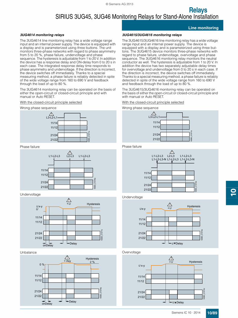
3UG4614 monitoring relays
The 3UG4614 line monitoring relay has a wide voltage range input and an internal power supply. The device is equipped with a display and is parameterized using three buttons. The unit monitors three-phase networks with regard to phase asymmetry from 5 to 20 %, phase failure, undervoltage and phase sequence. The hysteresis is adjustable from 1 to 20 V. In addition the device has a response delay and ON-delay from 0 to 20 s in each case. The integrated response delay time responds to phase asymmetry and undervoltage. If the direction is incorrect, the device switches off immediately. Thanks to a special measuring method, a phase failure is reliably detected in spite of the wide voltage range from 160 to 690 V and feedback through the load of up to 80 %.
The 3UG4614 monitoring relay can be operated on the basis of either the open-circuit or closed-circuit principle and with manual or Auto RESET.
With the closed-circuit principle selected
Wrong phase sequence
Phase failure
Undervoltage
Unbalance
3UG4615/3UG4616 monitoring relays
The 3UG4615/3UG4616 line monitoring relay has a wide voltage range input and an internal power supply. The device is equipped with a display and is parameterized using three but-tons. The 3UG4615 device monitors three-phase networks with regard to phase failure, undervoltage, overvoltage and phase sequence. The 3UG4616 monitoring relay monitors the neutral conductor as well. The hysteresis is adjustable from 1 to 20 V. In addition the device has two separately adjustable delay times for overvoltage and undervoltage from 0 to 20 s in each case. If the direction is incorrect, the device switches off immediately. Thanks to a special measuring method, a phase failure is reliably detected in spite of the wide voltage range from 160 to 690 V and feedback through the load of up to 80 %.
The 3UG4615/3UG4616 monitoring relay can be operated on the basis of either the open-circuit or closed-circuit principle and with manual or Auto RESET.
With the closed-circuit principle selected
Wrong phase sequence
Phase failure
Undervoltage
Overvoltage
NS
B0_
0157
1a
11/1411/12
21/2421/22
L3-L2-L1
NS
B0_
0157
6a
11/1411/12
21/24
21/22
L1-L2-L3L2-L3L1-L2-L3
<
21/2421/22
11/1411/12
x-yU
Hysteresis
DelayonDelay
NS
B0_
0157
7a
> AsyHysteresis
2 %
DelayonDelay
NS
B0_
0157
8a
21/2421/22
11/1411/12
0 %
NS
B0_
0157
1a
11/1411/12
21/2421/22
L3-L2-L1
NS
B0_
0157
2a
11/1411/12
21/2421/22
L1-L2-L3L1-L2-L3-N
L2-L3L1-L2-L3
L1-L2-L3L1-L2-L3-N
NS
B0_
0157
3a
<
21/24
21/22
11/1411/12
x-yHysteresis
Delay
NS
B0_
0157
4a
21/24
21/22
11/1411/12
<x-y
Hysteresis
Delay
SIRIUS_IC10_chap10_English_2014.book Seite 89 Freitag, 10. Januar 2014 12:08 12
© Siemens AG 2013

RelaysSIRIUS 3UG45, 3UG46 Monitoring Relays for Stand-Alone Installation
Line monitoring
10/90 Siemens IC 10 · 2014
10
3UG4617/3UG4618 monitoring relays
The 3UG4617/3UG4618 line monitoring relay has an internal power supply and can automatically correct a wrong direction of rotation. Thanks to a special measuring method, a phase failure is reliably detected in spite of the wide voltage range from 160 to 690 V AC and feedback through the load of up to 80 %. The device is equipped with a display and is parameterized using three buttons. The 3UG4617 line monitoring relay unit monitors three-phase networks with regard to phase sequence, phase failure, phase unbalance, undervoltage and overvoltage. The 3UG4618 monitoring relay monitors the neutral conductor as well. The hysteresis is adjustable from 1 to 20 V. In addition the device has delay times from 0 to 20 s in each case for overvoltage, undervoltage, phase failure and phase unbalance. The 3UG4617/3UG4618 monitoring relay can be operated on the basis of either the open-circuit or closed-circuit principle and with manual or Auto RESET. The one changeover contact is used for warning or disconnection in the event of power system faults (voltage, unbalance), the other responds only to a wrong phase sequence. In conjunction with a contactor reversing assembly it is thus possible to change the direction automatically.
With the closed-circuit principle selected
Phase failure
Undervoltage
Overvoltage
Unbalance
Circuit diagrams
NS
B0_
0158
7a
11/14
50 ms11/12
21/2421/22
L1-L2-L3L1-L2-L3-N
L2-L3L1-L2-L3
L1-L2-L3L1-L2-L3-N
NS
B0_
0158
8a
11/14
50 ms
11/12
21/2421/22
<x-yHysteresis
Delay
NS
B0_
0158
9a
11/14
50 ms
11/12
21/2421/22
x-y> Hysteresis
Delay
NS
B0_
0159
0a
11/14
50 ms
11/12
21/2421/22
> Asy0 %
Hysteresis2 %
Delay
Type 3UG4511 ... 3UG4513, 3UG4614 ... 3UG4618General dataRated insulation voltage UiPollution degree 3Overvoltage category III acc. to VDE 0110
V 690
Rated impulse withstand voltage Uimp kV 6Control circuit
Load capacity of the output relay
• Conventional thermal current Ith A 5
Rated operational current Ie at
• AC-15/24 ... 400 V A 3• DC-13/24 V A 1• DC-13/125 V A 0.2• DC-13/250 V A 0.1
Minimum contact load at 17 V DC mA 5
Electrical endurance AC-15 Million operating cycles 0.1
Mechanical endurance Million operating cycles 10
Note:It is not necessary to protect the measuring circuit for device protection. The protective device for line protection depends on the cross-section used.
3UG4511-.A,3UG4512-.A
3UG4511-.B, 3UG4512-.B,3UG4513, 3UG4614,3UG4615, 3UG4617
3UG4616,3UG4618
3UG4
L1
L3L2
L3L2
14
11
12
L1
NSB0_01537a
3UG4
24
21
22
L1
L3L2
L3L2
14
11
12
L1
NSB0_01536a
3UG4
N
N
24
21
22
L1
L3L2
L3L2
14
11
12
L1
NSB0_01538a
SIRIUS_IC10_chap10_English_2014.book Seite 90 Freitag, 10. Januar 2014 12:08 12
© Siemens AG 2013

RelaysSIRIUS 3UG45, 3UG46 Monitoring Relays for Stand-Alone Installation
Line monitoring
10/91Siemens IC 10 · 2014* You can order this quantity or a multiple thereof.Illustrations are approximate
10
■ Selection and ordering data
PU (UNIT, SET, M) = 1PS* = 1 unitPG = 41H
✓ Function available
-- Function not available
1) Absolute limit values.2) 1 CO contact each and 1 tripping delay time each for Umin and Umax.3) 1 CO contact each for power system fault and phase sequence correction.
For accessories see page 10/122.
Adjustable hysteresis
Under-voltage detec-tion
Over-voltage detec-tion
Stabiliza-tion time adjustablestDEL
Tripping delay time adjustable Del
Version of auxiliary contacts
Measurable mains voltage1)
DT Screw terminals
DT Spring-type terminals
s s CO con-tact
VArticle No. Price
per PUArticle No. Price
per PU
Monitoring of phase sequenceAuto RESET
-- -- -- -- -- 1 160 … 260 AC A 3UG4511-1AN20 A 3UG4511-2AN202 A 3UG4511-1BN20 A 3UG4511-2BN20
1 320 … 500 AC A 3UG4511-1AP20 A 3UG4511-2AP202 A 3UG4511-1BP20 A 3UG4511-2BP20
1 420 … 690 AC A 3UG4511-1AQ20 A 3UG4511-2AQ202 A 3UG4511-1BQ20 A 3UG4511-2BQ20
Monitoring of phase sequence, phase failure and phase unbalanceAuto RESET, closed-circuit principle, unbalance threshold permanently 10 %
-- -- -- -- -- 1 160 … 690 AC A 3UG4512-1AR20 A 3UG4512-2AR202 A 3UG4512-1BR20 A 3UG4512-2BR20
Monitoring of phase sequence, phase failure, unbalance and undervoltage Analogically adjustable, Auto RESET, closed-circuit principle, unbalance and undervoltage threshold permanently 20 %
5 % of set value
✓ -- -- 0.1 … 20 2 160 … 690 AC A 3UG4513-1BR20 A 3UG4513-2BR20
Digitally adjustable, Auto or Manual RESET, open-circuit or closed-circuit principle, unbalance threshold 0 or 5 ... 20 %
Adjustable 1 ... 20 V
✓ -- 0.1 ... 20 0.1 … 20 2 160 … 690 AC A 3UG4614-1BR20 A 3UG4614-2BR20
Monitoring of phase sequence, phase failure, overvoltage and undervoltage Digitally adjustable, Auto RESET or Manual RESET, open-circuit or closed-circuit principle
Adjustable 1 ... 20 V
✓ ✓ -- 0.1 … 202) 22) 160 … 690 AC A 3UG4615-1CR20 A 3UG4615-2CR20
Monitoring of phase sequence, phase and N conductor failure, overvoltage and undervoltage Digitally adjustable, Auto RESET or Manual RESET, open-circuit or closed-circuit principle
Adjustable 1 ... 20 V
✓ ✓ -- 0.1 … 202) 22) 90… 400 AC against N
A 3UG4616-1CR20 A 3UG4616-2CR20
Automatic direction correction in case of wrong phase sequence, phase failure, phase unbalance, overvoltage and undervoltage Digitally adjustable, Auto or Manual RESET, open-circuit or closed-circuit principle, unbalance threshold 0 or 5 ... 20 %
Adjustable 1 ... 20 V
✓ ✓ -- 0.1 … 20 23) 160 … 690 AC A 3UG4617-1CR20 A 3UG4617-2CR20
Automatic correction of the direction of rotation in case of wrong phase sequence, phase and N conductor failure, phase unbalance, overvoltage and undervoltage Digitally adjustable, Auto or Manual RESET, open-circuit or closed-circuit principle, unbalance threshold 0 or 5 ... 20 %
Adjustable 1 ... 20 V
✓ ✓ -- 0.1 … 20 23) 90 … 400 AC against N
A 3UG4618-1CR20 A 3UG4618-2CR20
3UG4511-2BP203UG4511-1AP20 3UG4615-1CR20 3UG4616-1CR20 3UG4512-2BR203UG4617-1CR20 3UG4618-1CR20
SIRIUS_IC10_chap10_English_2014.book Seite 91 Freitag, 10. Januar 2014 12:08 12
© Siemens AG 2013

RelaysSIRIUS 3UG45, 3UG46 Monitoring Relays for Stand-Alone Installation
Voltage monitoring
10/92 Siemens IC 10 · 2014
10
■ Overview
SIRIUS 3UG4631 monitoring relay
The relays monitor single-phase AC voltages (rms value) and DC voltages against the set threshold value for overshoot and undershoot. The devices differ with regard to their power supply (internal or external).
■ Benefits
• Versions with wide voltage supply range• Variably adjustable to overshoot, undershoot or range
monitoring• Freely configurable delay times and RESET response• Width 22.5 mm• Display of ACTUAL value and status messages• All versions with removable terminals• All versions with screw or spring-type terminals
■ Application
• Protection of a plant against destruction due to overvoltage• Switch-on of a plant at a defined voltage and higher• Protection from undervoltage due to overloaded control
supply voltages, particularly with battery power• Threshold switch for analog signals from 0.1 to 10 V
■ Technical specifications
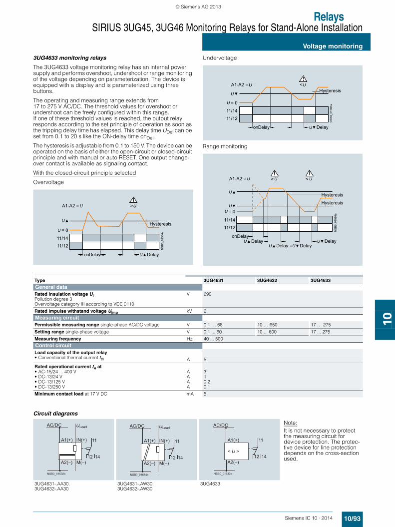
3UG4631/3UG4632 monitoring relays
The 3UG4631/3UG4632 voltage monitoring relay is supplied with an auxiliary voltage of 24 V AC/DC or 24 to 240 V AC/DC and performs overshoot, undershoot or range monitoring of the voltage depending on parameterization. The device is equipped with a display and is parameterized using three buttons.
The measuring range extends from 0.1 to 60 V or 10 to 600 V AC/DC. The threshold values for overshoot or undershoot can be freely configured within this range. If one of these threshold values is reached, the output relay responds according to the set principle of operation as soon as the delay time has elapsed. This delay time UDel can be set from 0.1 to 20 s. The hysteresis can be set from 0.1 to 30 V or 0.1 to 300 V. The device can be operated on the basis of either the open-circuit or closed-circuit principle and with manual or Auto RESET. One output changeover contact is available as signaling contact.
With the closed-circuit principle selected
Overvoltage
Undervoltage
Range monitoring
11/1411/12
A1-A2
>
= 0 Hysteresis
Delay
NS
B0_
0158
1a
11/1411/12
A1-A2
<
= 0
Hysteresis
Delay
NS
B0_
0158
2a
> <
Hysteresis
Hysteresis
Delay DelayDelay = Delay
NS
B0_
0158
3b
11/1411/12
A1-A2
SIRIUS_IC10_chap10_English_2014.book Seite 92 Freitag, 10. Januar 2014 12:08 12
© Siemens AG 2013
RelaysSIRIUS 3UG45, 3UG46 Monitoring Relays for Stand-Alone Installation
10/93Siemens IC 10 · 2014
Voltage monitoring
10
3UG4633 monitoring relays
The 3UG4633 voltage monitoring relay has an internal power supply and performs overshoot, undershoot or range monitoring of the voltage depending on parameterization. The device is equipped with a display and is parameterized using three buttons.
The operating and measuring range extends from 17 to 275 V AC/DC. The threshold values for overshoot or undershoot can be freely configured within this range. If one of these threshold values is reached, the output relay responds according to the set principle of operation as soon as the tripping delay time has elapsed. This delay time UDel can be set from 0.1 to 20 s like the ON-delay time onDel.
The hysteresis is adjustable from 0.1 to 150 V. The device can be operated on the basis of either the open-circuit or closed-circuit principle and with manual or auto RESET. One output change-over contact is available as signaling contact.
With the closed-circuit principle selected
Overvoltage
Undervoltage
Range monitoring
Circuit diagrams
NS
B0_
0158
4a
11/1411/12
= 0
A1-A2 = >
Hysteresis
DelayonDelay
11/1411/12
= 0
A1-A2 = <Hysteresis
DelayonDelay
NS
B0_
0158
5a
>
11/1411/12
<A1-A2 =
= 0
Hysteresis
Hysteresis
DelayonDelay
Delay =Delay
Delay
NS
B0_
0158
6a
Type 3UG4631 3UG4632 3UG4633General data
Rated insulation voltage UiPollution degree 3Overvoltage category III according to VDE 0110
V 690
Rated impulse withstand voltage Uimp kV 6Measuring circuit
Permissible measuring range single-phase AC/DC voltage V 0.1 … 68 10 … 650 17 … 275
Setting range single-phase voltage V 0.1 ... 60 10 ... 600 17 ... 275
Measuring frequency Hz 40 ... 500Control circuit
Load capacity of the output relay
• Conventional thermal current Ith A 5
Rated operational current Ie at
• AC-15/24 ... 400 V A 3• DC-13/24 V A 1• DC-13/125 V A 0.2• DC-13/250 V A 0.1
Minimum contact load at 17 V DC mA 5
Note:It is not necessary to protect the measuring circuit for device protection. The protec-tive device for line protection depends on the cross-section used.
3UG4631-.AA30, 3UG4632-.AA30
3UG4631-.AW30, 3UG4632-.AW30
3UG4633
< U
M(–)A2(–)
IN(+)
U
A1(+)
14
11
12
NSB0_01532b
AC/DC Load
< U M(–)A2(–)
IN(+)
U
A1(+)
14
11
12
NSB0_01614a
AC/DC Load
NSB0_01533b
12
11
14
A1(+)
A2(–)
< U >
AC/DC
SIRIUS_IC10_chap10_English_2014.book Seite 93 Freitag, 10. Januar 2014 12:08 12
© Siemens AG 2013

RelaysSIRIUS 3UG45, 3UG46 Monitoring Relays for Stand-Alone Installation
Voltage monitoring
10/94 Siemens IC 10 · 2014* You can order this quantity or a multiple thereof.
Illustrations are approximate
10
■ Selection and ordering data
• Digitally adjustable, with illuminated LCD• Auto or Manual RESET• Open or closed-circuit principle• 1 CO contact
PU (UNIT, SET, M) = 1PS* = 1 unitPG = 41H
1) Absolute limit values.
For accessories see page 10/122.
Measuring range Adjustablehysteresis
Rated control supply voltage Us
DT Screw terminals DT Spring-type
terminals
V V VArticle No. Price
per PUArticle No. Price
per PUInternal power supply without auxiliary voltage, ON-delay and tripping delay times can be adjusted separately 0.1 ... 20 s 17 … 275 AC/DC 0.1 ... 150 17 … 275 AC/DC1) A 3UG4633-1AL30 A 3UG4633-2AL30
Supplied from an external auxiliary voltage, tripping delay time adjustable 0.1 ... 20 s0.1 … 60 AC/DC 0.1 ... 30 24 AC/DC A 3UG4631-1AA30 A 3UG4631-2AA3010 … 600 AC/DC 0.1 ... 300 A 3UG4632-1AA30 A 3UG4632-2AA30
0.1 … 60 AC/DC 0.1 ... 30 24 … 240 AC/DC A 3UG4631-1AW30 A 3UG4631-2AW3010 … 600 AC/DC 0.1 ... 300 A 3UG4632-1AW30 A 3UG4632-2AW30
3UG4631-1AA30 3UG4633-2AL30
SIRIUS_IC10_chap10_English_2014.book Seite 94 Freitag, 10. Januar 2014 12:08 12
© Siemens AG 2013

RelaysSIRIUS 3UG45, 3UG46 Monitoring Relays for Stand-Alone Installation
10/95Siemens IC 10 · 2014
Current monitoring
10
■ Overview
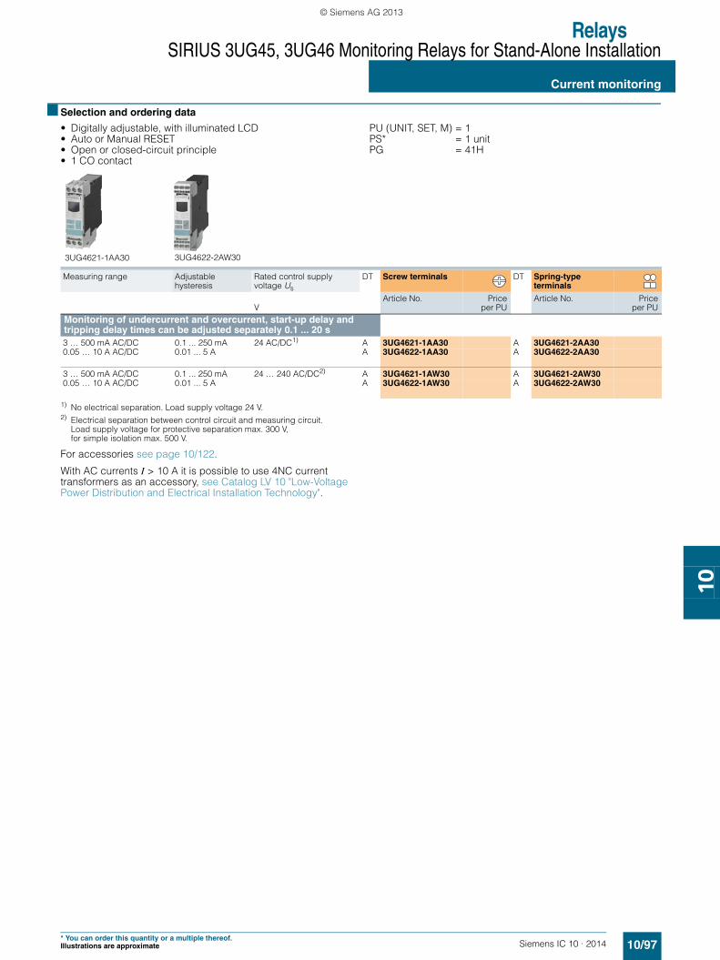
SIRIUS 3UG4622 monitoring relay
The relays monitor single-phase AC currents (rms value) and DC currents against the set threshold value for overshoot and undershoot. They differ with regard to their measuring ranges and control supply voltage types.
■ Benefits
• Versions with wide voltage supply range• Variably adjustable to overshoot, undershoot or range
monitoring• Freely configurable delay times and RESET response• Width 22.5 mm• Display of ACTUAL value and status messages• All versions with removable terminals• All versions with screw or spring-type terminals
■ Application
• Overcurrent and undercurrent monitoring• Monitoring the functionality of electrical loads• Open-circuit monitoring• Threshold switch for analog signals from 4 to 20 mA
■ Technical specifications
3UG4621/3UG4622 monitoring relays
The 3UG4621 or 3UG4622 current monitoring relay is supplied with an auxiliary voltage of 24 V AC/DC or 24 to 240 V AC/DC and performs overshoot, undershoot or range monitoring of the current depending on parameterization. The device is equipped with a display and is parameterized using three buttons.
The measuring range extends from 3 to 500 mA or 0.05 to 10 A. The rms value of the current is measured. The threshold values for overshoot or undershoot can be freely configured within this range. If one of these threshold values is reached, the output re-lay responds according to the set principle of operation as soon as the tripping delay time IDel has elapsed. This time and the ON-delay time onDel are adjustable from 0.1 to 20 s.
The hysteresis is adjustable from 0.1 to 250 mA or 0.01 to 5 A. The device can be operated with manual or Auto RESET and on the basis of either the open-circuit or closed-circuit principle. Following options are available: Response of the output relay when the control supply voltage Us = ON is applied or not until the lower measuring range limit of the measuring current (I > 3 mA/50 mA) is reached. One output changeover contact is available as signaling contact.
With the closed-circuit principle selectedupon application of the control supply voltage
Current overshoot
Current undershoot
Range monitoring
11/14
A1-A2
11/12
=0
>
Hysteresis
DelayonDelay
NS
B0_
0157
9a
<
Hysteresis
DelayonDelay
11/14
A1-A2
11/12
= 0
NS
B0_
0158
0a
> <
Hysteresis
Hysteresis
DelayDelayDelayDelay =
onDelay
NS
B0_
0162
6a
11/1411/12
A1-A2
= 0
SIRIUS_IC10_chap10_English_2014.book Seite 95 Freitag, 10. Januar 2014 12:08 12
© Siemens AG 2013

RelaysSIRIUS 3UG45, 3UG46 Monitoring Relays for Stand-Alone Installation
Current monitoring
10/96 Siemens IC 10 · 2014
10
1) With protective separation.2) With simple separation.
Circuit diagrams Connection diagram for 24 V AC/DC (only 3UG462.-.AA30)
From the following circuit diagrams it is clear that loads in measuring circuits have to be in the current flow upstream from the monitoring relay. Otherwise, the monitoring relay could be destroyed and the short-circuit current could cause damage to the plant.
Configuring note:
A2 and M are electrically connected internally.
For applications in which the load to be monitored and the monitoring relay are supplied from the same power supply, there is no need for connection A2.
The load current must always flow through M or the monitoring relay may be destroyed.
Type 3UG4621-.AA 3UG4621-.AW 3UG4622-.AA 3UG4622-.AWGeneral data
Rated insulation voltage UiPollution degree 3; overvoltage category III according to VDE 0110
V 690
Rated impulse withstand voltage Uimp kV 6Measuring circuit
Measuring range single-phase AC/DC current A 0.003 … 0.6 0.05 … 15
Setting range for single-phase current A 0.003 ... 0.5 0.05 ... 10
Load supply voltage V 24 Max. 3001)
Max. 5002)24 Max. 3001)
Max. 5002)
Control circuit
Load capacity of the output relay
• Conventional thermal current Ith A 5
Rated operational current Ie at
• AC-15/24 ... 400 V A 3• DC-13/24 V A 1• DC-13/125 V A 0.2• DC-13/250 V A 0.1
Minimum contact load at 17 V DC mA 5
3UG4621-.AA30,3UG4622-.AA30
3UG4621-.AA30,3UG4622-.AA30
Operation with separate control circuit and load circuit
Operation with joint control circuit and load circuit
3UG4621-.AW30, 3UG4622-.AW30
3UG4621-.AW30, 3UG4622-.AW30
Single-phase operation Three-phase operation
< >
11
14
NS
B0_
0153
4b
12A2 M
A1 IN
24 V AC/DC
MLoad
ULoadLoad
< >
11
14
NS
B0_
0170
8
12A2 M
A1 IN
24 V AC/DC
optional
Load
NS
B0_
0153
5b
11
14M
12
A1
A2
< >
IN
AC/DC
MLoad
LoadULoad
Load
12 14
11
AC/DC L1 L2 L3
MA2
INA1
< >
NS
B0_
0170
7
MLoad
24 V AC/DC
LoadULoad
o.k.
< >
IN
MA2
A1
NS
B0_
0119
9e
Load
24 V AC/DC
< >
A1 IN
L3 L2 L1
M A2
NS
B0_
0120
0e
o.k.
o.k.
< >
A2 M
A1 IN
NS
B0_
0119
7e Load
24 V AC/DC
< >
A2
A1
NS
B0_
0119
8e
o.k.
M
L1 L2 L3
IN
24 V AC/DC
Load
SIRIUS_IC10_chap10_English_2014.book Seite 96 Freitag, 10. Januar 2014 12:08 12
© Siemens AG 2013
RelaysSIRIUS 3UG45, 3UG46 Monitoring Relays for Stand-Alone Installation
Current monitoring
10/97Siemens IC 10 · 2014* You can order this quantity or a multiple thereof.Illustrations are approximate
10
■ Selection and ordering data
• Digitally adjustable, with illuminated LCD• Auto or Manual RESET• Open or closed-circuit principle• 1 CO contact
PU (UNIT, SET, M) = 1PS* = 1 unitPG = 41H
1) No electrical separation. Load supply voltage 24 V.2) Electrical separation between control circuit and measuring circuit.
Load supply voltage for protective separation max. 300 V, for simple isolation max. 500 V.
For accessories see page 10/122.
With AC currents I > 10 A it is possible to use 4NC current transformers as an accessory, see Catalog LV 10 "Low-Voltage Power Distribution and Electrical Installation Technology".
Measuring range
Adjustablehysteresis
Rated control supply voltage Us
DT Screw terminals DT Spring-type terminals
VArticle No. Price
per PUArticle No. Price
per PUMonitoring of undercurrent and overcurrent, start-up delay and tripping delay times can be adjusted separately 0.1 ... 20 s 3 … 500 mA AC/DC 0.1 ... 250 mA 24 AC/DC1) A 3UG4621-1AA30 A 3UG4621-2AA300.05 … 10 A AC/DC 0.01 ... 5 A A 3UG4622-1AA30 A 3UG4622-2AA30
3 … 500 mA AC/DC 0.1 ... 250 mA 24 … 240 AC/DC2) A 3UG4621-1AW30 A 3UG4621-2AW300.05 … 10 A AC/DC 0.01 ... 5 A A 3UG4622-1AW30 A 3UG4622-2AW30
3UG4621-1AA30 3UG4622-2AW30
SIRIUS_IC10_chap10_English_2014.book Seite 97 Freitag, 10. Januar 2014 12:08 12
© Siemens AG 2013

RelaysSIRIUS 3UG45, 3UG46 Monitoring Relays for Stand-Alone Installation
Power factor and active current monitoring
10/98 Siemens IC 10 · 2014
10
■ Overview
SIRIUS 3UG4641 monitoring relay
The 3UG4641 power factor and active current monitoring device enables the load monitoring of motors.
Whereas power factor monitoring is used above all for monitoring no-load operation, the active current monitoring option can be used to observe and evaluate the load factor over the entire torque range.
■ Benefits
• Can be used worldwide thanks to wide voltage range from 90 to 690 V (absolute limit values)
• Monitoring of even small single-phase motors with a no-load supply current below 0.5 A
• Simple determination of threshold values by the direct collection of measured variables on motor loading
• Range monitoring and active current measurement enable detection of cable breaks between control cabinets and motors, as well as phase failures
• Power factor or Ires (active current) can be selected as measurement principle
• Width 22.5 mm• All versions with removable terminals
■ Application
• No-load monitoring and load shedding, such as in the event of a V-belt tear
• Underload monitoring in the low performance range, e.g. in the event of pump no-load operation
• Monitoring of overload, e.g. due to a dirty filter system• Simple power factor monitoring in power systems for control of
compensation equipment• Broken cable between control cabinet and motor
■ Technical specifications
3UG4641 monitoring relays
The 3UG4641 monitoring relay is self-powered and serves the single-phase monitoring of the p.f. or performs overshoot, undershoot or range monitoring of the active current depending on how it is parameterized. The load to be monitored is connected upstream of the IN terminal. The load current flows through the terminals IN and Ly/N. The setting range for the power factor is 0.1 to 0.99 and for the active current Ires 0.2 to 10 A. If the control supply voltage is switched on and no load current flows, the display will show I < 0.2 and a symbol for overrange, underrange or range monitoring. If the motor is now switched on and the current exceeds 0.2 A, the set ON-delay time begins. During this time, if the set limit values are undershot or exceeded, this does not lead to a relay reaction of the changeover contact. If the operational flowing active current and/or the p.f. value falls below or exceeds the respective set threshold value, the spike delay begins. When this time has expired, the relay changes its switch position. The relevant measured variables for overshooting and undershooting in the display flash. If the monitoring of active current undershooting is deactivated (Ires▼= OFF) and the load current drops below the lower measuring range threshold (0.2 A), then the CO contacts remain unchanged. If a threshold value is set for the monitoring of active current undershooting, then undershooting of the measuring range threshold (0.2 A) will result in a response of the CO contacts.
The relay operates either according to the open-circuit or closed-circuit principle. If the device is set to Auto RESET (Memory = No), depending on the set principle of operation, the switching relay returns to its initial state and the flashing ends when the hysteresis threshold is reached.
If Manual RESET is selected in the menu (Memory = Yes), the switching relay remains in its current switching state and the current measured value and the symbol for undershooting and overshooting continues to flash, even when the measured variable reaches a permissible value again. This stored fault status can be reset by pressing the UP▲ or DOWN▼ key simultaneously for 2 seconds, or by switching the supply voltage off and back on again.
With the closed-circuit principle selected
Response in the event of undershooting the measuring range limit• With activated monitoring of Ires▼
• With deactivated monitoring of active current undershooting
21/22
21/24
11/12
11/14
Lx-Ly/N
I = 0,2 A
I = 0
I < 0,2 A
Ires
onDelayonDelay
NS
B0_
0165
8b
< 0,2 A
onDelayonDelay
NSB
0_01
917b
21/22
21/24
11/12
11/14
Lx-Ly/N
= 0,2 A
= 0
res = off
SIRIUS_IC10_chap10_English_2014.book Seite 98 Freitag, 10. Januar 2014 12:08 12
© Siemens AG 2013

RelaysSIRIUS 3UG45, 3UG46 Monitoring Relays for Stand-Alone Installation
10/99Siemens IC 10 · 2014
Power factor and active current monitoring
10
Overshooting of active current
Undershooting of active current
Range monitoring of active current
Overshooting of power factor
Undershooting of power factor
Range monitoring of power factor
21/24
21/22
11/14
11/12
> res
= 0
res
DelayonDelay
Hysteresis
NS
B0_
0165
9a
21/24
21/22
11/14
11/12
< res
= 0
res
DelayonDelay
Hysteresis
NS
B0_
0166
0a
< res> res
DelayonDelay Delay
Hysteresis
Hysteresis
NS
B0_
0166
1a21/24
21/22
11/14
11/12
= 0
res
res
21/24
21/22
11/14
11/12
p.f. cos φ = 0
cos φ
DelayonDelay
Hysteresis 0,10
NS
B0_
0166
2b
> cos φ
cos φ = 0
cos φ
< cos φ
Hysteresis 0,10
DelayonDelay
NS
B0_
0166
3b21/24
21/22
11/14
11/12
p.f.
21/24
21/22
11/14
11/12
p.f.
< cos φ
cos φ = 0
Hysteresis0,10
DelayonDelay Delay
NS
B0_
0166
4b
> cos φ
cos φ
cos φ
SIRIUS_IC10_chap10_English_2014.book Seite 99 Freitag, 10. Januar 2014 12:08 12
© Siemens AG 2013

RelaysSIRIUS 3UG45, 3UG46 Monitoring Relays for Stand-Alone Installation
Power factor and active current monitoring
10/100 Siemens IC 10 · 2014* You can order this quantity or a multiple thereof.
Illustrations are approximate
10
Circuit diagrams
■ Selection and ordering data
• For monitoring the power factor and the active current Ires (p.f. x I)
• Suitable for single- and three-phase currents• Digitally adjustable, with illuminated LCD• Overshoot, undershoot or range monitoring adjustable• Upper and lower threshold value can be adjusted separately• Permanent display of actual value and tripping state• 1 changeover contact each for undershoot/overshoot
PU (UNIT, SET, M) = 1PS* = 1 unitPG = 41H
1) Absolute limit values.
For accessories see page 10/122.
With AC active currents Ires > 10 A it is possible to use 4NC current transformers as an accessory, see Catalog LV 10 "Low-Voltage Power Distribution and Electrical Installation Technology".
Type 3UG4641General dataRated insulation voltage UiPollution degree 3Overvoltage category III acc. to VDE 0110
V 690
Rated impulse withstand voltage Uimp kV 6Control circuit
Number of CO contacts for auxiliary contacts 2
Load capacity of the output relay
• Conventional thermal current Ith A 5
Rated operational current Ie at
• AC-15/24 ... 400 V A 3• DC-13/24 V A 1• DC-13/125 V A 0.2• DC-13/250 V A 0.1
Minimum contact load at 17 V DC mA 5
Single-phase motors Three-phase motors Three-phase motors with transformers for currents > 10 A
M1~
Lx IN
12
14
22
24
N/L
L/N
21
NSB0_01654c
r/
r/3UG4641
11
Ly/N
cos φ
cos φ
Lx IN
12
14
22
24
LnLnLnn = 1,2,3
21
M3~
11
Ly/N
3UG4641/ r
/ r
NSB0_01655c
cos φ
cos φ
Lx IN
12
14
22
2421
M3~
LnLnLnn = 1,2,3
r/
r/
NSB0_01656c
3UG464111
Ly/N
cos φ
cos φ
Measuring range Adjustablehysteresis
ON-delay time adjust-able onDel
Tripping delay time adjustableI▲Del/I▼Del, ▲Del/ ▼Del
Rated control supply voltage Us
1)
DT Screw terminals DT Spring-type terminals
For power factor
For active current Ires
For power factor
For active current Ires
50/60 Hz AC
P.f. A P.f. A s s VArticle No. Price
per PUArticle No. Price
per PU
0.10 ... 0.99 0.2 ... 10.0 0.1 0.1 ... 2.0 0 ... 99 0.1 ... 20.0 90 ... 690 A 3UG4641-1CS20 A 3UG4641-2CS20
SIRIUS_IC10_chap10_English_2014.book Seite 100 Freitag, 10. Januar 2014 12:08 12
© Siemens AG 2013
RelaysSIRIUS 3UG45, 3UG46 Monitoring Relays for Stand-Alone Installation
10/101Siemens IC 10 · 2014
Residual current monitoring:Residual-current monitoring relays
10
■ Overview
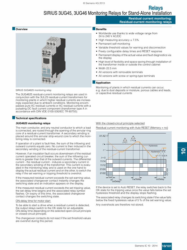
SIRIUS 3UG4625 monitoring relay
The 3UG4625 residual-current monitoring relays are used in conjunction with the 3UL23 residual-current transformers for monitoring plants in which higher residual currents are increas-ingly expected due to ambient conditions. Monitoring encom-passes pure AC residual currents or AC residual currents with a pulsating DC fault current component (transformer type A in accordance with DIN VDE 0100-530/IEC TR 60755).
■ Benefits
• Worldwide use thanks to wide voltage range from 24 to 240 V AC/DC
• High measuring accuracy ± 7.5%• Permanent self-monitoring• Variable threshold values for warning and disconnection• Freely configurable delay times and RESET response• Permanent display of the actual value and fault diagnostics via
the display• High level of flexibility and space saving through installation of
the transformer inside or outside the control cabinet• Width 22.5 mm• All versions with removable terminals• All versions with screw or spring-type terminals
■ Application
Monitoring of plants in which residual currents can occur, e.g. due to dust deposits or moisture, porous cables and leads, or capacitive residual currents
■ Technical specifications
3UG4625 monitoring relays
The main conductor, and any neutral conductor to which a load is connected, are routed through the opening of the annular ring core of a residual-current transformer. A secondary winding is placed around this annular strip-wound core to which the moni-toring relay is connected.
If operation of a plant is fault-free, the sum of the inflowing and outward currents equals zero. No current is then induced in the secondary winding of the residual-current transformer.
However, if an insulation fault occurs downstream of the residual current operated circuit breaker, the sum of the inflowing cur-rents is greater than that of the outward currents. The differential current - the residual current - induces a secondary current in the secondary winding of the transformer. This current is evalu-ated in the monitoring relay and is used on the one hand to display the actual residual current and on the other, to switch the relay if the set warning or tripping threshold is overshot.
If the measured residual current exceeds the set warning value, the associated changeover contact instantly changes the switching state and an indication appears on the display.
If the measured residual current exceeds the set tripping value, the set delay time begins and the associated relay symbol flashes. On expiry of this time, the associated changeover contact changes the switching state.
ON-delay time for motor start
To be able to start a drive when a residual current is detected, the output relays switch to the OK state for an adjustable ON-delay time depending on the selected open-circuit principle or closed-circuit principle.
The changeover contacts do not react if the set threshold values are overshot during this period.
With the closed-circuit principle selected
Residual current monitoring with Auto RESET (Memory = no)
If the device is set to Auto RESET, the relay switches back to the OK state for the tripping value once the value falls below the set hysteresis threshold and the display stops flashing.
The associated relay changes its switching state if the value falls below the fixed hysteresis value of 5 % of the set warning value.
Any overshoots are therefore not stored.
!
> > !
Hysteresis
= 0,02 A
Hysteresis = 5 %
onDelayonDelay
InitDelay
IC01
_002
25
A1-A2
11/14
11/12
21/24
21/22
= 0
SIRIUS_IC10_chap10_English_2014.book Seite 101 Freitag, 10. Januar 2014 12:08 12
© Siemens AG 2013
RelaysSIRIUS 3UG45, 3UG46 Monitoring Relays for Stand-Alone InstallationResidual current monitoring: Residual-current monitoring relays
10/102 Siemens IC 10 · 2014
10
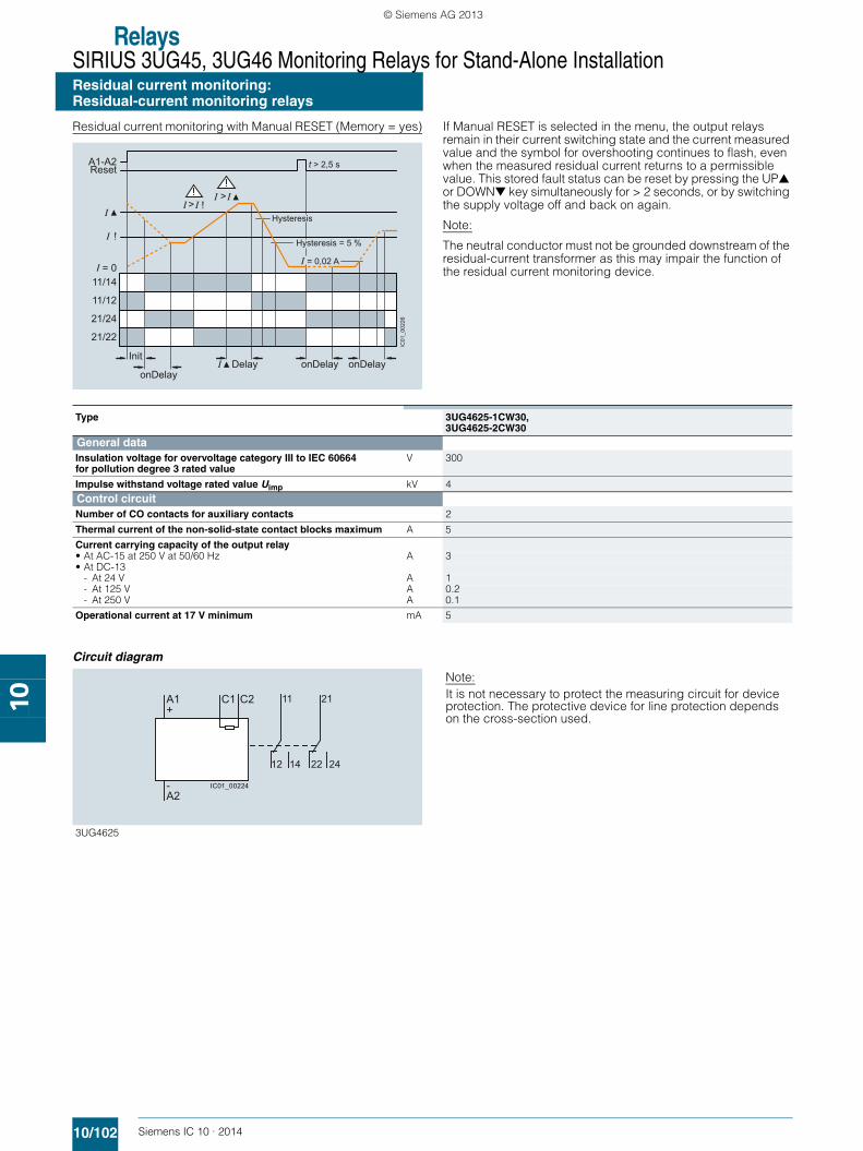
Residual current monitoring with Manual RESET (Memory = yes) If Manual RESET is selected in the menu, the output relays remain in their current switching state and the current measured value and the symbol for overshooting continues to flash, even when the measured residual current returns to a permissible value. This stored fault status can be reset by pressing the UP▲ or DOWN▼ key simultaneously for > 2 seconds, or by switching the supply voltage off and back on again.
Note:
The neutral conductor must not be grounded downstream of the residual-current transformer as this may impair the function of the residual current monitoring device.
Circuit diagram
!
> > !
Hysteresis
= 0,02 A
Hysteresis = 5 %
Delay onDelayonDelayonDelay
Init
t > 2,5 sA1-A2Reset
11/14
11/12
21/24
21/22
= 0
IC01
_002
26
Type 3UG4625-1CW30,3UG4625-2CW30
General dataInsulation voltage for overvoltage category III to IEC 60664 for pollution degree 3 rated value
V 300
Impulse withstand voltage rated value Uimp kV 4Control circuit
Number of CO contacts for auxiliary contacts 2
Thermal current of the non-solid-state contact blocks maximum A 5
Current carrying capacity of the output relay
• At AC-15 at 250 V at 50/60 Hz A 3• At DC-13
- At 24 V A 1- At 125 V A 0.2- At 250 V A 0.1
Operational current at 17 V minimum mA 5
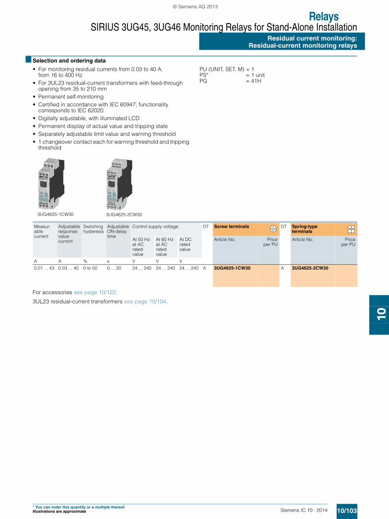
Note:It is not necessary to protect the measuring circuit for device protection. The protective device for line protection depends on the cross-section used.
3UG4625
12 14 22 24
2111A1 +
- A2
C2C1
IC01_00224
SIRIUS_IC10_chap10_English_2014.book Seite 102 Freitag, 10. Januar 2014 12:08 12
© Siemens AG 2013
RelaysSIRIUS 3UG45, 3UG46 Monitoring Relays for Stand-Alone Installation
Residual current monitoring:Residual-current monitoring relays
10/103Siemens IC 10 · 2014* You can order this quantity or a multiple thereof.Illustrations are approximate
10
■ Selection and ordering data
• For monitoring residual currents from 0.03 to 40 A, from 16 to 400 Hz
• For 3UL23 residual-current transformers with feed-through opening from 35 to 210 mm
• Permanent self-monitoring• Certified in accordance with IEC 60947, functionality
corresponds to IEC 62020• Digitally adjustable, with illuminated LCD• Permanent display of actual value and tripping state• Separately adjustable limit value and warning threshold• 1 changeover contact each for warning threshold and tripping
threshold
PU (UNIT, SET, M) = 1 PS* = 1 unit PG = 41H
For accessories see page 10/122.
3UL23 residual-current transformers see page 10/104.
Measur-able current
Adjustable response value current
Switching hysteresis
Adjustable ON-delay time
Control supply voltage DT Screw terminals DT Spring-type terminals
At 50 Hz at AC rated value
At 60 Hz at AC rated value
At DC rated value
Article No. Priceper PU
Article No. Priceper PU
A A % s V V V
0.01 ... 43 0.03 ... 40 0 to 50 0 ... 20 24 ... 240 24 ... 240 24 ... 240 A 3UG4625-1CW30 A 3UG4625-2CW30
3UG4625-1CW30 3UG4625-2CW30
SIRIUS_IC10_chap10_English_2014.book Seite 103 Freitag, 10. Januar 2014 12:08 12
© Siemens AG 2013

RelaysSIRIUS 3UG45, 3UG46 Monitoring Relays for Stand-Alone InstallationResidual current monitoring: Residual-current transformers
10/104 Siemens IC 10 · 2014* You can order this quantity or a multiple thereof.
Illustrations are approximate
10
■ Overview
SIRIUS 3UL23 residual-current transformer
The 3UL23 residual-current transformers detect residual currents in machines and plants. They are suitable for pure AC residual currents or AC residual currents with a pulsating DC fault current component (transformer type A in accordance with DIN VDE 0100-530/IEC TR 60755).
Together with the 3UG4625, 3UG4825 residual-current monitor-ing relays for IO-Link or the SIMOCODE 3UF motor management and control device they enable residual-current and ground-fault monitoring.
The 3UL2302-1A and 3UL2303-1A residual-current transformers with a feed-through opening from 35 to 55 mm can be mounted in conjunction with the 3UL2900 accessories on a TH 35 stan-dard mounting rail according to IEC 60715.
■ Technical specifications
Dimension drawing
■ Selection and ordering data
■ Accessories
Type
b
c a
IC01
_002
29a
de
f
a
355580110140210
d
505050505046
e
646464646462
3UL2302-1A3UL2303-1A3UL2304-1A3UL2305-1A3UL2306-1A3UL2307-1A
6,2
f
-- 386084,5110161
b
7092124,5163201300
c
75,598130169207,5286
Diameter of the bushing opening Connectable cross-section of the connecting terminal
DT Screw terminals PU(UNIT,
SET, M)
PS* PG
mm mm2Article No. Price
per PUResidual-current transformer (essential accessory for 3UG4625, 3UG4825 or SIMOCODE 3UF)
35 2.5 B 3UL2302-1A 1 1 unit 41H55 2.5 B 3UL2303-1A 1 1 unit 41H80 2.5 B 3UL2304-1A 1 1 unit 41H
110 2.5 B 3UL2305-1A 1 1 unit 41H140 2.5 B 3UL2306-1A 1 1 unit 41H210 4 B 3UL2307-1A 1 1 unit 41H
Version DT Article No. Priceper PU
PU(UNIT,
SET, M)
PS* PG
Adapters
3UL2900
Adapters
For mounting onto standard railfor 3UL23 to diameter 55 mm
A 3UL2900 1 2 units 41H
SIRIUS_IC10_chap10_English_2014.book Seite 104 Freitag, 10. Januar 2014 12:08 12
© Siemens AG 2013

RelaysSIRIUS 3UG45, 3UG46 Monitoring Relays for Stand-Alone Installation
10/105Siemens IC 10 · 2014
Insulation monitoring:General data
10
■ Overview
SIRIUS 3UG458. insulation monitor
Insulation monitoring relays are used for monitoring the insulation resistance between ungrounded single or three-phase AC supplies and a protective conductor.
Ungrounded, i.e. isolated networks (IT networks) are always used where high demands are placed on the reliability of the power supply, e.g. emergency lighting systems. IT systems are supplied via an isolating transformer or by power supply sources such as batteries or a generator. While an initial insulation fault between a phase conductor and the ground effectively grounds the conductor, as a result no circuit has been closed, so it is pos-sible to continue work in safety (single-fault safety). However, the fault must be rectified as quickly as possible before a second insulation fault occurs (e.g. according to DIN VDE 0100-410). For this purpose insulation monitoring relays are used, which constantly measure the resistance to ground of the phase conductor and the neutral conductor, reporting a fault immedi-ately if insulation resistance falls below the set value so that either a controlled shutdown can be performed or the fault can be rectified without interrupting the power supply.
Two series• 3UG4581 insulation monitoring relays for ungrounded
AC networks• 3UG4582 and 3UG4583 insulation monitoring relays for
ungrounded DC and AC networks
■ Benefits
• Devices for AC and DC systems• All devices have a wide control supply voltage range• Direct connection to networks with mains voltages of up to
690 V AC and 1 000 V DC by means of a voltage reducer module
• For AC supply systems: Frequency range 15 to 400 Hz• Monitoring of broken conductors• Monitoring of setting errors• Safety in use thanks to integrated system test after start-up • Option of resetting and testing (by means of button on front or
using control contact) • New predictive measurement principle allows very fast
response times
■ Application
IT networks are used for example:• In emergency power supplies• In safety lighting systems• In industrial production facilities with high availability require-
ments (chemical industry, automobile manufacturing, printing plants)
• In shipping and railways• For mobile generators (aircraft)• For renewable energies, such as wind energy and
photovoltaic power plants• In the mining industry
SIRIUS_IC10_chap10_English_2014.book Seite 105 Freitag, 10. Januar 2014 12:08 12
© Siemens AG 2013
RelaysSIRIUS 3UG45, 3UG46 Monitoring Relays for Stand-Alone InstallationInsulation monitoring:General data
10/106 Siemens IC 10 · 2014
10
■ Technical specifications
✓ Available
-- Not available
1) With voltage reducer module.
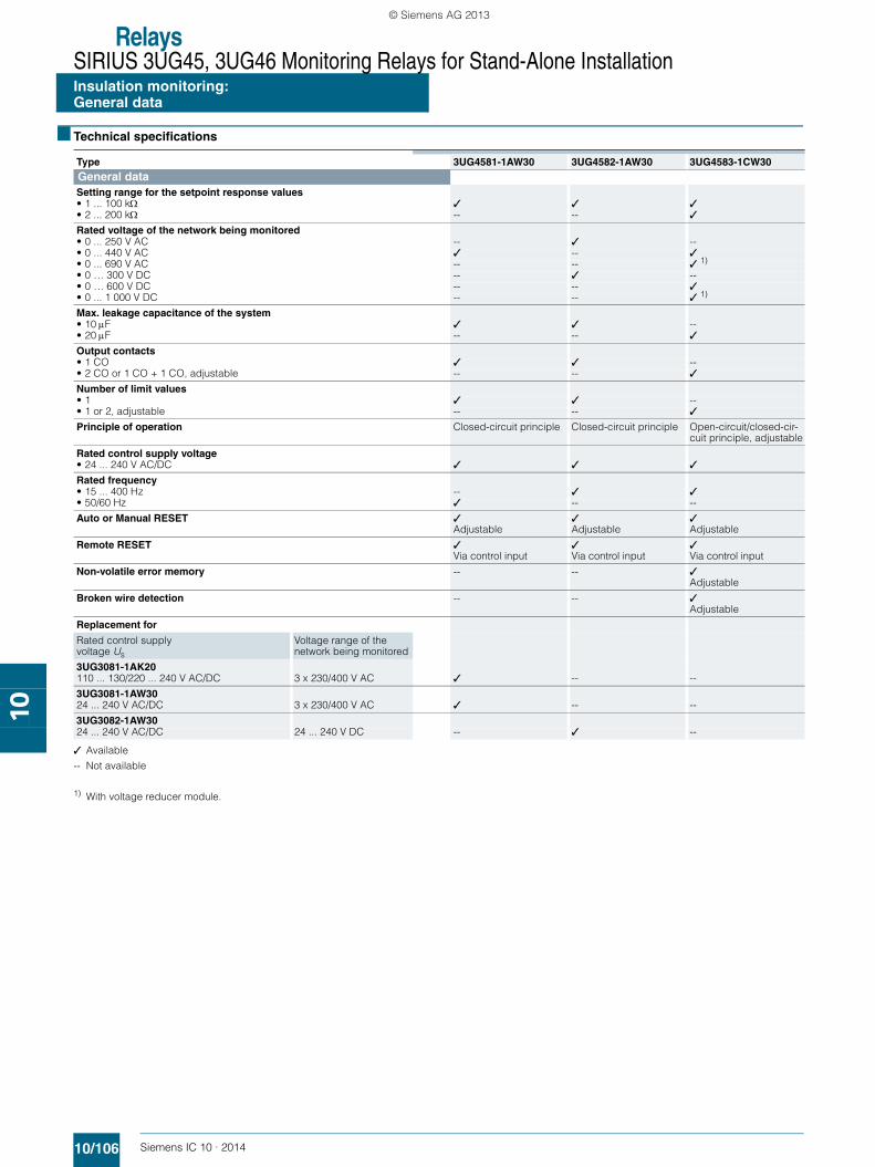
Type 3UG4581-1AW30 3UG4582-1AW30 3UG4583-1CW30General dataSetting range for the setpoint response values• 1 ... 100 k ✓ ✓ ✓• 2 ... 200 k -- -- ✓
Rated voltage of the network being monitored
• 0 ... 250 V AC -- ✓ --• 0 ... 440 V AC ✓ -- ✓• 0 ... 690 V AC -- -- ✓ 1) • 0 … 300 V DC -- ✓ --• 0 … 600 V DC -- -- ✓• 0 ... 1 000 V DC -- -- ✓ 1)
Max. leakage capacitance of the system• 10F ✓ ✓ --• 20F -- -- ✓
Output contacts• 1 CO ✓ ✓ --• 2 CO or 1 CO + 1 CO, adjustable -- -- ✓
Number of limit values• 1 ✓ ✓ --• 1 or 2, adjustable -- -- ✓
Principle of operation Closed-circuit principle Closed-circuit principle Open-circuit/closed-cir-cuit principle, adjustable
Rated control supply voltage• 24 ... 240 V AC/DC ✓ ✓ ✓
Rated frequency• 15 ... 400 Hz -- ✓ ✓• 50/60 Hz ✓ -- --
Auto or Manual RESET ✓Adjustable
✓Adjustable
✓Adjustable
Remote RESET ✓Via control input
✓Via control input
✓Via control input
Non-volatile error memory -- -- ✓Adjustable
Broken wire detection -- -- ✓Adjustable
Replacement for
Rated control supplyvoltage Us
Voltage range of the network being monitored
3UG3081-1AK20110 ... 130/220 ... 240 V AC/DC 3 x 230/400 V AC ✓ -- --
3UG3081-1AW3024 ... 240 V AC/DC 3 x 230/400 V AC ✓ -- --
3UG3082-1AW3024 ... 240 V AC/DC 24 ... 240 V DC -- ✓ --
SIRIUS_IC10_chap10_English_2014.book Seite 106 Freitag, 10. Januar 2014 12:08 12
© Siemens AG 2013

RelaysSIRIUS 3UG45, 3UG46 Monitoring Relays for Stand-Alone Installation
10/107Siemens IC 10 · 2014
Insulation monitoringfor ungrounded AC networks
10
■ Overview
SIRIUS 3UG4581 insulation monitor
The 3UG4581 insulation monitoring relays are used to monitor insulation resistance according to IEC 61557-8 in ungrounded AC networks with rated voltages of up to 400 V.
These devices can monitor control circuits (single-phase) and main circuits (three-phase).
They measure insulation resistances between system cables and system ground. If the value falls below the threshold value, the output relays are switched to fault status.
In the case of 3UG4581 a higher-level DC measuring signal is used. The higher-level DC measuring signal and the resulting current are used to determine the value of the insulation resis-tance of the network which is to be measured.
■ Technical specifications
3UG4581 monitoring relays
With the closed-circuit principle selected
Insulation resistance monitoring without fault storage, with Auto RESET
Insulation resistance monitoring with fault storage and Manual RESET
F
Closed-circuit principle
Threshold valueHysteresis
Measured value
: yellow LED
: red LED
: green LED
IC01
_000
74
Y2-Y3
Y1-Y3
A1+/A2-
11-1411-12
st Closed-circuit principleThreshold value
HysteresisMeasured value
: yellow LED
: red LED
: green LED
Y2-Y3
Y1-Y3
A1+/A2-
11-1411-12
IC01
_000
75
st
F
SIRIUS_IC10_chap10_English_2014.book Seite 107 Freitag, 10. Januar 2014 12:08 12
© Siemens AG 2013

RelaysSIRIUS 3UG45, 3UG46 Monitoring Relays for Stand-Alone InstallationInsulation monitoringfor ungrounded AC networks
10/108 Siemens IC 10 · 2014
10
Circuit diagram
Type 3UG4581
Dimensions (W x H x D) mm 22.5 x 100 x 100
Connection type Screw terminals
• Solid mm2 2 x (0.5 ... 4)• Finely stranded with end sleeve mm2 2 x (0.75 ... 2.5)• AWG cables, solid or stranded AWG 2 x (20 ... 14)General data
Rated insulation voltage Ui Pollution degree 3Overvoltage category III acc. to IEC 60664
V 400 supply circuit/measuring circuit300 supply circuit/output circuit
Rated impulse withstand voltage Uimp kV 6
Rated control supply voltage V 24 ... 240 AC/DC
Rated frequency Hz 15 ... 400 Measuring circuit
Rated mains voltage of the network being monitored V 0 ... 400
Rated frequency of the network being monitored Hz 50 ... 60
Setting range for insulation resistance k 1 ... 100 Control circuit
Load capacity of the output relay
• Conventional thermal current Ith A 4
Rated operational current Ie at
• AC-15/24 ... 400 V A 3• DC-13/24 V A 2
Minimum contact load at 24 V DC mA 10
W
H
D
Note:
It is not necessary to protect the measuring circuit for device protection. The protective device for line protection depends on the cross-section used.
3UG4581
kΩ
IC01_00141
1412
11
A2
A1
L
SIRIUS_IC10_chap10_English_2014.book Seite 108 Freitag, 10. Januar 2014 12:08 12
© Siemens AG 2013

RelaysSIRIUS 3UG45, 3UG46 Monitoring Relays for Stand-Alone Installation
Insulation monitoringfor ungrounded AC networks
10/109Siemens IC 10 · 2014* You can order this quantity or a multiple thereof.Illustrations are approximate
10
Connection diagrams for networks up to 400 V AC
■ Selection and ordering data
• Auto or Manual RESET• Closed-circuit principle• 1 CO contact• Fault memory adjustable using control input (Y2-Y3)• Reset by means of button on front or using control input
(Y2-Y3)• Test by means of button on front or using control input
(Y1-Y3)
For accessories see page 10/122.
3-wire
4-wire
2-wire
IC01
_000
76
L
NPE
A1+Y1 Y2 Y3
11
LA2-14 12
L1L2L3PE
L1L2L3NPE
Rated mains voltage Un
Measuring range Ue
Rated control supply voltage Us
System leakage capaci-tance
DT Screw terminals PU(UNIT,
SET, M)
PS* PG
V AC k V FArticle No. Price
per PU
Insulation monitors for ungrounded AC networks
3UG4581-1AW30
0 ... 400 1 ... 100 24 ... 240 AC/DC max. 10 B 3UG4581-1AW30 1 1 unit 41H
SIRIUS_IC10_chap10_English_2014.book Seite 109 Freitag, 10. Januar 2014 12:08 12
© Siemens AG 2013

RelaysSIRIUS 3UG45, 3UG46 Monitoring Relays for Stand-Alone InstallationInsulation monitoringfor ungrounded DC and AC networks
10/110 Siemens IC 10 · 2014
10
■ Overview
SIRIUS 3UG4582 and 3UG4583 insulation monitors
The 3UG4582 and 3UG4583 insulation monitoring relays are used to monitor insulation resistance in ungrounded IT AC or DC networks according to IEC 61557-8.
They measure insulation resistances between system cables and system ground. If the value falls below the threshold value, the output relays are switched to fault status. With these devices, which are suitable for both AC and DC networks, a pulsed test signal is fed into the network to be monitored and the isolation resistance is determined.
The pulsed test signal changes its form according to insulation resistance and network loss capacitance. The changed form is used to predict the changed insulation resistance.
If the predicted insulation resistance matches the insulation re-sistance calculated in the next measurement cycle, and is lower than the threshold value, the output relays are activated or deac-tivated, depending on the device configuration. This measure-ment principle is also suitable for identifying symmetrical insula-tion faults.
3UG4983 voltage reducer module
The 3UG4983 passive voltage reducer module can be used to allow the 3UG4583 insulation monitoring relay to be used for insulation monitoring of IT networks with rated voltages of up to 690 V AC and 1 000 V DC.
■ Technical specifications
3UG4582 monitoring relays
With the closed-circuit principle selected
Insulation resistance monitoring without fault storage, with Auto RESET
Insulation resistance monitoring with fault storage and Manual RESET
F
Closed-circuit principle
Threshold valueHysteresis
Measured value
: yellow LED
: red LED
: green LED
IC01
_000
74
Y2-Y3
Y1-Y3
A1+/A2-
11-1411-12
st Closed-circuit principleThreshold value
HysteresisMeasured value
: yellow LED
: red LED
: green LED
Y2-Y3
Y1-Y3
A1+/A2-
11-1411-12
IC01
_000
75
st
F
SIRIUS_IC10_chap10_English_2014.book Seite 110 Freitag, 10. Januar 2014 12:08 12
© Siemens AG 2013

RelaysSIRIUS 3UG45, 3UG46 Monitoring Relays for Stand-Alone Installation
10/111Siemens IC 10 · 2014
Insulation monitoringfor ungrounded DC and AC networks
10
3UG4583 monitoring relays
With the closed-circuit principle selected
Insulation resistance monitoring without fault storage, with Auto RESET
Insulation resistance monitoring with fault storage and Manual RESET
closed
open
F
F
Final switch-offHysteresis
PrewarningHysteresis
Measured Value
Closed-circuitprinciple
Open-circuitprinciple
IC01
_000
83
LED
LED
LED
21-2421-24
11-1411-12
LED
LED
LED
21-2221-24
11-1411-12
Y2-Y3
Y1-Y3
A1+/A2-
st
closed
open
Final switch-offHysteresis
PrewarningHysteresis
Measured Value
Closed-circuitprinciple
Open-circuitprinciple
IC01
_000
84
LED
LED
LED
21-2421-24
11-1411-12
LED
LED
LED
21-2221-24
11-1411-12
Y2-Y3
Y1-Y3
A1+/A2-
stst
F
F
Type 3UG4582 3UG4583
Dimensions (W x H x D) mm 22.5 x 100 x 100 45 x 100 x 100
Connection type Screw terminals
• Solid mm2 2 x (0.5 ... 4)• Finely stranded with end sleeve mm2 2 x (0.75 ... 2.5)• AWG cables, solid or stranded AWG 2 x (20 ... 14)General data
Rated insulation voltage Ui Pollution degree 3Overvoltage category III acc. to IEC 60664
V 400 supply circuit/measuring circuit, 300 supply circuit/output circuit
400 supply circuit/measuring circuit300 supply circuit/output circuit,300 output circuit 1/output circuit 2
Rated impulse withstand voltage Uimp kV 6
Rated control supply voltage V AC/DC 24 ... 240
Rated frequency Hz 15 ... 400 Measuring circuit
Rated mains voltage of the network being monitored VV
0 ... 250 AC,0 ... 300 DC
0 ... 300 AC, 0 ... 690 AC with 3UG49830 ... 600 DC, 0 ... 1 000 DC with 3UG4983
Rated frequency of the network being monitored Hz DC or 15 ... 400
Setting range for insulation resistance k 1 ... 100 1 ... 1002 ... 200 for 2nd limit value (disconnectable)
Control circuit
Number of CO contacts for auxiliary contacts 1 2 or 1 + 1, adjustable
Load capacity of the output relay • Conventional thermal current Ith A 4
Rated operational current Ie at • AC-15/24 ... 400 V A 3• DC-13/24 V A 2
Minimum contact load at 24 V DC mA 10
W
H
D
SIRIUS_IC10_chap10_English_2014.book Seite 111 Freitag, 10. Januar 2014 12:08 12
© Siemens AG 2013
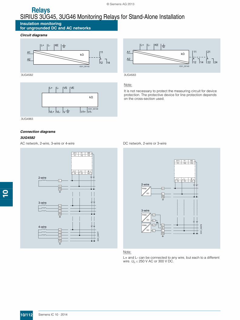
RelaysSIRIUS 3UG45, 3UG46 Monitoring Relays for Stand-Alone InstallationInsulation monitoringfor ungrounded DC and AC networks
10/112 Siemens IC 10 · 2014
10
Circuit diagrams
Connection diagrams
3UG4582
AC network, 2-wire, 3-wire or 4-wire DC network, 2-wire or 3-wire
Note:
L+ and L- can be connected to any wire, but each to a different wire. Un 250 V AC or 300 V DC.
3UG4582 3UG4583
Note:
It is not necessary to protect the measuring circuit for device protection. The protective device for line protection depends on the cross-section used.
3UG4983
kΩ
1412
11
A2
A1
KEL-L+
IC01_00142
kΩ21
24221412
11
A2
A1
KEL-L+
IC01_00140
kΩ
IC01_00139
L+ L- VEVS
VL+ VL- V1+ V1-V
3-wire
4-wire
2-wire
IC01
_000
77
L
NPE
A1+Y1 Y2 Y3
KE11
L-L+A214 12
L1L2L3PE
L1L2L3NPE
3-wire
2-wire
IC01
_000
78
A1+Y1 Y2 Y3
KE11
L-L+A214 12
PWM
DC
L+
L-PE
PWM
PWM
DC
DC
L+L+ML-L-PE
L+
L-
SIRIUS_IC10_chap10_English_2014.book Seite 112 Freitag, 10. Januar 2014 12:08 12
© Siemens AG 2013
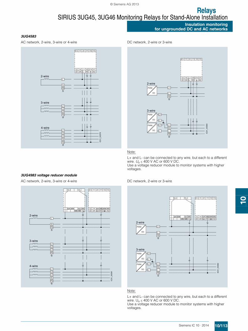
RelaysSIRIUS 3UG45, 3UG46 Monitoring Relays for Stand-Alone Installation
10/113Siemens IC 10 · 2014
Insulation monitoringfor ungrounded DC and AC networks
10
3UG4583
AC network, 2-wire, 3-wire or 4-wire DC network, 2-wire or 3-wire
Note:
L+ and L- can be connected to any wire, but each to a different wire. Un 400 V AC or 600 V DC. Use a voltage reducer module to monitor systems with higher voltages.
3UG4983 voltage reducer module
AC network, 2-wire, 3-wire or 4-wire DC network, 2-wire or 3-wire
Note:
L+ and L- can be connected to any wire, but each to a different wire. Un 400 V AC or 600 V DC.Use a voltage reducer module to monitor systems with higher voltages.
3-wire
4-wire
2-wire
IC01
_000
79
L
NPE
A1+ 11 Y2 Y321 Y1
L+ VS12 14A2-V1-V1+
22 24 L- KE
L1L2L3PE
L1L2L3NPE
3-wire
2-wire
IC01
_000
80
PWM
DC
L+
L-PE
A1+ 11 Y2 Y321 Y1
L+ VS12 14A2-V1-V1+
22 24 L- KE
PWM
PWM
DC
DC
L+L+ML-L-PE
L+
L-
3-wire
4-wire
2-wire
IC01
_000
81
L
NPE
VL+ A1+ 11 Y2 Y321 Y1
L+ VS12 14A2-V1-V1+
22 24 L- KE
VL-
VL-L+VE
V1-V1+VS
L1L2L3PE
L1L2L3NPE
3-wire
2-wire
IC01
_000
82
PWM
DC
L+
L-PE
VL+ A1+ 11 Y2 Y321 Y1
L+ VS12 14A2-V1-V1+
22 24 L- KE
VL-
VL-L+VE
V1-V1+VS
PWM
PWM
DC
DC
L+L+ML-L-PE
L+
L-
SIRIUS_IC10_chap10_English_2014.book Seite 113 Freitag, 10. Januar 2014 12:08 12
© Siemens AG 2013
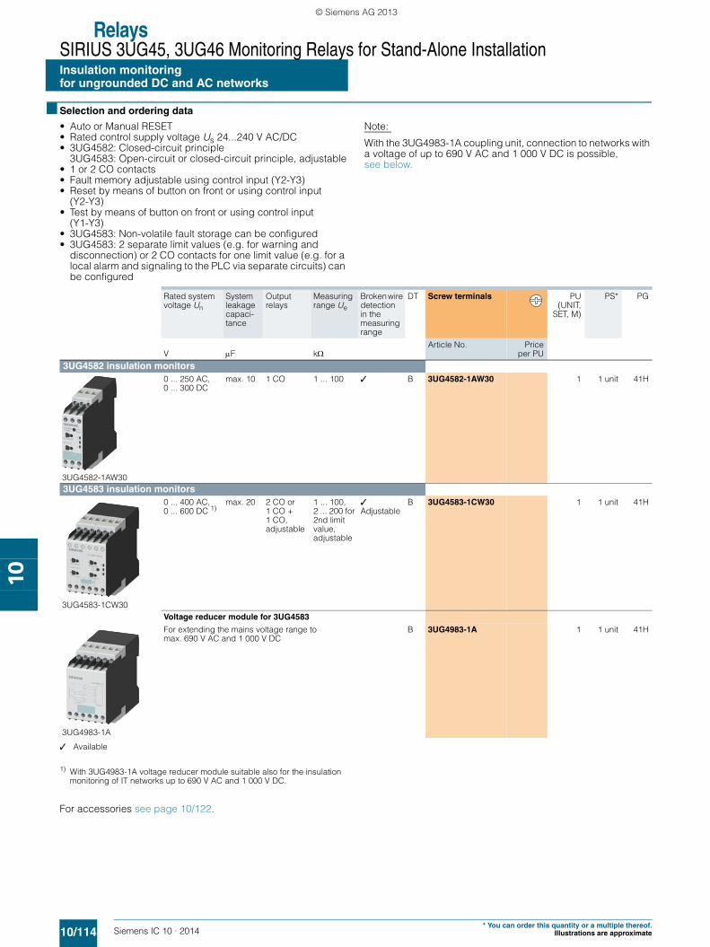
RelaysSIRIUS 3UG45, 3UG46 Monitoring Relays for Stand-Alone InstallationInsulation monitoringfor ungrounded DC and AC networks
10/114 Siemens IC 10 · 2014* You can order this quantity or a multiple thereof.
Illustrations are approximate
10
■ Selection and ordering data
• Auto or Manual RESET• Rated control supply voltage Us 24...240 V AC/DC• 3UG4582: Closed-circuit principle
3UG4583: Open-circuit or closed-circuit principle, adjustable• 1 or 2 CO contacts• Fault memory adjustable using control input (Y2-Y3)• Reset by means of button on front or using control input
(Y2-Y3)• Test by means of button on front or using control input
(Y1-Y3)• 3UG4583: Non-volatile fault storage can be configured• 3UG4583: 2 separate limit values (e.g. for warning and
disconnection) or 2 CO contacts for one limit value (e.g. for a local alarm and signaling to the PLC via separate circuits) can be configured
Note:
With the 3UG4983-1A coupling unit, connection to networks with a voltage of up to 690 V AC and 1 000 V DC is possible, see below.
✓ Available
1) With 3UG4983-1A voltage reducer module suitable also for the insulation monitoring of IT networks up to 690 V AC and 1 000 V DC.
For accessories see page 10/122.
Rated system voltage Un
System leakage capaci-tance
Output relays
Measuring range Ue
Broken wire detection in the measuring range
DT Screw terminals PU(UNIT,
SET, M)
PS* PG
V F kArticle No. Price
per PU
3UG4582 insulation monitors
3UG4582-1AW30
0 ... 250 AC,0 ... 300 DC
max. 10 1 CO 1 ... 100 ✓ B 3UG4582-1AW30 1 1 unit 41H
3UG4583 insulation monitors
3UG4583-1CW30
0 ... 400 AC, 0 ... 600 DC 1)
max. 20 2 CO or 1 CO + 1 CO, adjustable
1 ... 100, 2 ... 200 for 2nd limit value, adjustable
✓Adjustable
B 3UG4583-1CW30 1 1 unit 41H
Voltage reducer module for 3UG4583
3UG4983-1A
For extending the mains voltage range to max. 690 V AC and 1 000 V DC
B 3UG4983-1A 1 1 unit 41H
SIRIUS_IC10_chap10_English_2014.book Seite 114 Freitag, 10. Januar 2014 12:08 12
© Siemens AG 2013

RelaysSIRIUS 3UG45, 3UG46 Monitoring Relays for Stand-Alone Installation
10/115Siemens IC 10 · 2014
Level monitoring:Level monitoring relays
10
■ Overview
SIRIUS 3UG4501 monitoring relay
The 3UG4501 level monitoring relay is used in combination with 2- or 3-pole sensors to monitor the levels of conductive liquids.
■ Benefits
• Can be used worldwide thanks to wide voltage range from 24 to 240 V (absolute limit values)
• Individually shortenable 2 and 3-pole wire electrodes for easy mounting from above/below
• Bow electrodes for installation from the side, for larger filling levels and minimum space requirements
• Can be flexibly adapted to different conductive liquids through analog setting of the sensitivity from 2 to 200 k
• Compensation for wave movements through tripping delay times from 0.1 to 10 s
• Upstream or downstream function selectable• All versions with removable terminals• All versions with screw or spring-type terminals
■ Application
• Single-point and two-point level monitoring• Overflow protection• Dry run protection• Leak monitoring
■ Technical specifications
3UG4501 monitoring relays
The principle of operation of the 3UG4501 level monitoring relay is based on measuring the electrical resistance of the liquid between two immersion sensors and a reference terminal. If the measured value is lower than the sensitivity set at the front, the output relay changes its switching state. In order to exclude electrolytic phenomena in the liquid, the sensors are supplied with alternating current.
Two-point control
The output relay changes its switching state as soon as the liquid level reaches the maximum sensor, while the minimum sensor is submerged. The relay returns to its original switching state as soon as the minimum sensor no longer has contact with the liquid.
OVER, two-point control
UNDER, two-point control
Note:
It is also possible to connect other resistance sensors to the Min and Max terminals in the range 2 to 200 kW, e.g. photoresistors, temperature sensors, encoders based on resistance, etc. The monitoring relay can therefore also be used for other applica-tions as well as for monitoring the levels of liquids.
11/14
A1/A2
t t
11/12
t t
NS
B0_
0179
9b
Max
Min
t = Delay 0,5 - 10 s
> 0,5 s + t
RESET
tt t t
t = Delay 0,5 - 10 s
> 0,5 s + t
RESET
NS
B0_
0180
0b
Max
Min
11/14
A1/A2
11/12
SIRIUS_IC10_chap10_English_2014.book Seite 115 Freitag, 10. Januar 2014 12:08 12
© Siemens AG 2013
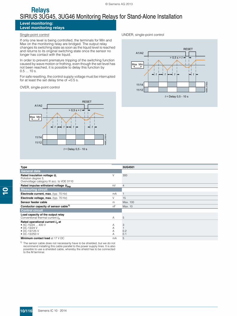
RelaysSIRIUS 3UG45, 3UG46 Monitoring Relays for Stand-Alone InstallationLevel monitoring:Level monitoring relays
10/116 Siemens IC 10 · 2014
10
Single-point control
If only one level is being controlled, the terminals for Min and Max on the monitoring relay are bridged. The output relay changes its switching state as soon as the liquid level is reached and returns to its original switching state once the sensor no longer has contact with the liquid.
In order to prevent premature tripping of the switching function caused by wave motion or frothing, even though the set level has not been reached, it is possible to delay this function by 0.5 ... 10 s.
For safe resetting, the control supply voltage must be interrupted for at least the set delay time of +0.5 s.
OVER, single-point control
UNDER, single-point control
1) The sensor cable does not necessarily have to be shielded, but we do not recommend installing this cable parallel to the power supply lines. It is also possible to use a shielded cable, whereby the shield has to be connected to the M terminal.
> 0,5 s + t
11/14
A1/A2
t t
11/12
t t
Max Min
t = Delay 0,5 - 10 s
RESETN
SB
0_01
801b
11/14
A1/A2
t t
11/12
t t
Max Min
t = Delay 0,5 - 10 s
> 0,5 s + t
RESET
NS
B0_
0180
2c
Type 3UG4501General dataRated insulation voltage UiPollution degree 3, Overvoltage category III acc. to VDE 0110
V 300
Rated impulse withstand voltage Uimp kV 4Measuring circuit
Electrode current, max. (typ. 70 Hz) mA 1
Electrode voltage, max. (typ. 70 Hz) V 15
Sensor feeder cable m Max. 100
Conductor capacity of sensor cable1) nF Max. 10Control circuit
Load capacity of the output relay
Conventional thermal current Ith A 5
Rated operational current Ie at
• AC-15/24 ... 400 V A 3• DC-13/24 V A 1• DC-13/125 V A 0.2• DC-13/250 V A 0.1
Minimum contact load at 17 V DC mA 5
SIRIUS_IC10_chap10_English_2014.book Seite 116 Freitag, 10. Januar 2014 12:08 12
© Siemens AG 2013

RelaysSIRIUS 3UG45, 3UG46 Monitoring Relays for Stand-Alone Installation
Level monitoring:Level monitoring relays
10/117Siemens IC 10 · 2014* You can order this quantity or a multiple thereof.Illustrations are approximate
10
Circuit diagrams
■ Selection and ordering data
• For level monitoring of electrically conductive liquids• Control principle: inlet or sequence control adjustable per
rotary switch • Single-point and two-point control possible• Analogically adjustable sensitivity
(specific resistance of the liquid)• Analogically adjustable tripping delay time• 1 yellow LED for displaying the relay state• 1 green LED for displaying the applied control supply voltage• 1 CO contact
PU (UNIT, SET, M) = 1PS* = 1 unitPG = 41H
1) The rated control supply voltage and the measuring circuit are not electrically separated.
For accessories see page 10/122.
For level monitoring sensors see page 10/118.
Schematic circuit diagram Circuit example of two-point control with outlet monitoring
Circuit example of single-point control with inlet monitoring
AC/+U
AC/0V
A1 (+) M
NSB0_01796bA2 (–)
11
12 14
3UG4501Max Min A1 (+)
A2 (–)
M
11
12 14K1
AC/+U
AC/0V NSB0_01797b
K1
Max Min3UG4501
NSB0_01798b
A1 (+)
A2 (–)
M
11
12 14K1
AC/+U
AC/0V
K1
Max Min3UG4501
Sensitivity Tripping delay time Rated control supply voltage Us
DT Screw terminals DT Spring-type terminals
k sVAC/DC
Article No. Priceper PU
Article No. Priceper PU
2 ... 200 0.5 ... 10 241) A 3UG4501-1AA30 A 3UG4501-2AA30
24 ... 240 A 3UG4501-1AW30 A 3UG4501-2AW30
SIRIUS_IC10_chap10_English_2014.book Seite 117 Freitag, 10. Januar 2014 12:08 12
© Siemens AG 2013

RelaysSIRIUS 3UG45, 3UG46 Monitoring Relays for Stand-Alone InstallationLevel monitoring:Level monitoring sensors
10/118 Siemens IC 10 · 2014* You can order this quantity or a multiple thereof.
Illustrations are approximate
10
■ Technical specifications
Dimensional drawings
■ Selection and ordering data
Type 3UG3207-3Athree-pole
3UG3207-2Atwo-pole
3UG3207-2Btwo-pole
3UG3207-1Bsingle-pole
3UG3207-1Csingle-pole
Length mm 500 --
Insulation Teflon insulation (PTFE) Yes -- Yes
Installation Vertical Lateral
Screw-in gland width A/F 22
Thread inch R 3/8
Connecting cable mm2 3 x 0.5, 2 m long
Operating temperature °C 90
Operating pressure bar 10
Cable/electrode assignment
• Cable brown Center electrode Not assignable Gland
• Cable white Not assignable Electrode
• Cable green Not assignable -- Not assignable --
3UG3207-3A 3UG3207-2A 3UG3207-1C 3UG3207-2B 3UG3207-1B
Version DT Article No. Priceper PU
PU(UNIT,
SET, M)
PS* PG
Level monitoring sensors (essential accessory)The wire electrodes can be cut or bent to the required length before or after installation. The Teflon insulation must be removed over a length of approx. 5 mm.
3UG3207-3A
Three-pole wire electrodes, 500 mm long
For 2-point liquid level control in an insulating tank. One electrode each for the min. and max. value and a common reference electrode.
A 3UG3207-3A 1 1 unit 41H
3UG3207-2A
Two-pole wire electrodes, 500 mm long
For alarm indication in the event of overflow or low level and for 2-point liquid level control, when the conductive tank is used as the reference electrode.
A 3UG3207-2A 1 1 unit 41H
3UG3207-2B
Two-pole bow electrodes
Thanks to the small space requirements due to lateral fitting, ideal for use in small containers and pipes, as a leak monitor and level monitor or for warning of water entering an enclosure.
A 3UG3207-2B 1 1 unit 41H
3UG3207-1B
Single-pole bow electrodes for lateral fitting
As a max. value electrode for lateral fitting or for alarm indication in conductive tanks or pipes.
A 3UG3207-1B 1 1 unit 41H
3UG3207-1C
Single-pole rod electrodes for lateral fitting
For high flow velocities or for intensively sparkling fluids.
A 3UG3207-1C 1 1 unit 41H
NS
B0_
0099
1a
SW 22
500
1515
5
1515
SW 22
500
5N
SB0_
0099
2
NSB0_00995
5040
SW 22
1515
PTFE insulation
15157±16±1
0,5
SW 22
5 NSB0_00993a
15157±16±1
0,5
SW 22
NSB0_00994
SIRIUS_IC10_chap10_English_2014.book Seite 118 Freitag, 10. Januar 2014 12:08 12
© Siemens AG 2013

RelaysSIRIUS 3UG45, 3UG46 Monitoring Relays for Stand-Alone Installation
10/119Siemens IC 10 · 2014
Speed monitoring
10
■ Overview
SIRIUS 3UG4651 monitoring relay
The 3UG4651 monitoring relay is used in combination with a sensor to monitor motor drives for overspeed and/or under-speed.
Furthermore, the monitoring relay is ideal for all functions where a continuous pulse signal needs to be monitored (e.g. belt travel monitoring, completeness monitoring, passing monitoring, clock-time monitoring).
■ Benefits
• Can be used worldwide thanks to wide voltage range from 24 to 240 V (absolute limit values)
• Variably adjustable to overshoot, undershoot or range monitoring
• Freely configurable delay times and RESET response• Permanent display of actual value and fault type• Use of up to 10 sensors per revolution on motors rotating
extremely slowly• 2- or 3-wire sensors and sensors with a mechanical switching
output or solid-state-output can be connected• Auxiliary voltage for sensor integrated• All versions with removable terminals• All versions with screw or spring-type terminals
■ Application
• Slip or tear of a belt drive• Overload monitoring• Transport monitoring for completeness
■ Technical specifications
3UG4651 monitoring relays
The speed monitoring relay operates according to the principle of period duration measurement.
In the monitoring relay, the time between two successive rising edges of the pulse encoder is measured and compared to the minimum and/or maximum permissible period duration calcu-lated from the set limit values for the speed.
Thus, the period duration measurement recognizes any devia-tion in speed after just two pulses, even at very low speeds or in the case of extended pulse gaps.
By using up to ten pulse encoders evenly distributed around the circumference, it is possible to shorten the period duration, and in turn the response time. By taking into account the number of sensors in the monitoring relay, the speed continues to be indi-cated in rpm.
ON-delay time for motor start
To be able to start a motor drive, and depending on whether the open-circuit or closed-circuit principle is selected, the output re-lay switches to the GO state during the ON-delay time, even if the speed is still below the set value.
The ON-delay time is started by either switching on the auxiliary voltage or, if the auxiliary voltage is already applied, by actuating the respective NC contact (e.g. auxiliary contact).
Speed monitoring with Auto RESET (Memory = no)
If the device is set to Auto RESET, the output relay switches to the GO state, once the adjustable hysteresis threshold is reached in the range of 0.1 ... 99.9 rpm and the flashing stops. Any overshoots or undershoots are therefore not stored.
Speed monitoring with Manual RESET (Memory = yes)
If Manual RESET is selected in the menu, the output relay re-mains in its current switching state and the current measured value and the symbol for overshooting/undershooting continue to flash, even when the speed returns to a permissible value. This stored fault status can be reset by pressing the UP▲ and DOWN▼ buttons simultaneously for > 2 s, by connecting the RESET device terminal to 24 V DC or by switching the control supply voltage off and back on again.
SIRIUS_IC10_chap10_English_2014.book Seite 119 Freitag, 10. Januar 2014 12:08 12
© Siemens AG 2013

RelaysSIRIUS 3UG45, 3UG46 Monitoring Relays for Stand-Alone Installation
Speed monitoring
10/120 Siemens IC 10 · 2014
10
With the closed-circuit principle selected
Range monitoring without enable input Range monitoring with enable input
11/14
A1/A2
11/12N
SB
0_01
803b
onDelay Delay Delay
Hysteresis
Hysteresis
RPM = 0
rpm
rpm> RPM < RPM
NS
B0_
0180
4a
11/14
A1/A2
EN
11/12
onDelay Delay Delay
Hysteresis
Hysteresis
RPM = 0
rpm
> RPM < RPMrpm
Type 3UG4651General dataRated insulation voltage UiPollution degree 3, Overvoltage category III acc. to VDE 0110
V 300
Rated impulse withstand voltage Uimp kV 4Measuring circuit
Sensor supply• For three-wire sensor (24 V/0 V) mA Max. 50• For 2-wire NAMUR sensor (8V2) mA Max. 8.2
Signal input• IN1 k 16, three-wire sensor, pnp operation• IN2 k 1, floating contact, 2-wire NAMUR sensor
Voltage level• For level 1 at IN1 V 4.5 ... 30• For level 0 at IN1 V 0 ... 1
Current level• For level 1 at IN2 mA > 2.1• For level 0 at IN2 mA < 1.2
Minimum pulse duration of signal ms 5
Minimum interval between 2 pulses ms 5Control circuitNumber of CO contacts for auxiliary contacts 1
Load capacity of the output relay
Conventional thermal current Ith A 5
Rated operational current Ie at
• AC-15/24 ... 400 V A 3• DC-13/24 V A 1• DC-13/125 V A 0.2• DC-13/250 V A 0.1
Minimum contact load at 17 V DC mA 5
SIRIUS_IC10_chap10_English_2014.book Seite 120 Freitag, 10. Januar 2014 12:08 12
© Siemens AG 2013
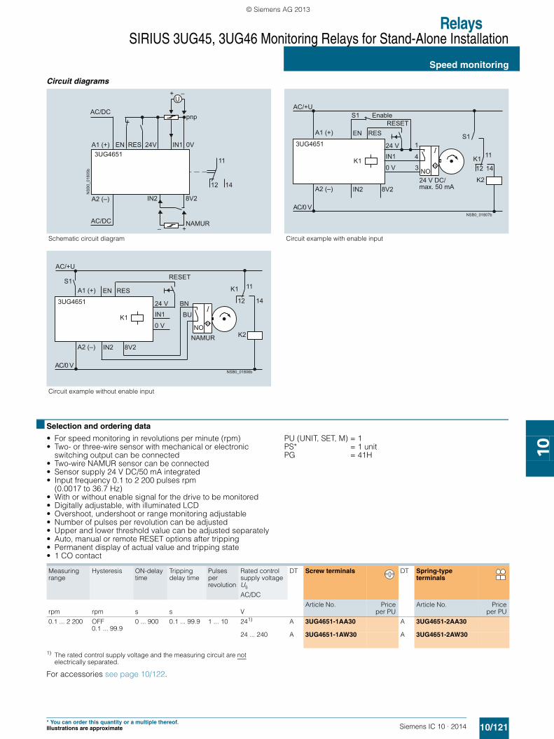
RelaysSIRIUS 3UG45, 3UG46 Monitoring Relays for Stand-Alone Installation
Speed monitoring
10/121Siemens IC 10 · 2014* You can order this quantity or a multiple thereof.Illustrations are approximate
10
Circuit diagrams
■ Selection and ordering data
• For speed monitoring in revolutions per minute (rpm)• Two- or three-wire sensor with mechanical or electronic
switching output can be connected• Two-wire NAMUR sensor can be connected• Sensor supply 24 V DC/50 mA integrated• Input frequency 0.1 to 2 200 pulses rpm
(0.0017 to 36.7 Hz)• With or without enable signal for the drive to be monitored• Digitally adjustable, with illuminated LCD• Overshoot, undershoot or range monitoring adjustable• Number of pulses per revolution can be adjusted• Upper and lower threshold value can be adjusted separately• Auto, manual or remote RESET options after tripping• Permanent display of actual value and tripping state• 1 CO contact
PU (UNIT, SET, M) = 1PS* = 1 unitPG = 41H
1) The rated control supply voltage and the measuring circuit are not electrically separated.
For accessories see page 10/122.
Schematic circuit diagram Circuit example with enable input
Circuit example without enable input
U
AC/DC
AC/DC
A1 (+) EN RES 24V IN1
IN2 8V2
+ –
0V
pnp
A2 (–)
3UG4651
NS
B0_
0180
5b
11
12 14
– +NAMUR
A2 (–) IN2 8V2
A1 (+) EN
S1
RES
1
4
3 NO
S1
12
11K1
K2
14
24 VIN1
0 V
3UG4651
NSB0_01807b
K1
AC/+U
AC/0 V
24 V DC/max. 50 mA
RESETEnable
AC/+U
S1
A2 (–) IN2 8V2
RESENA1 (+)
24 V BN
BU
NO
AC/0 V
12 14
11K1
K2
IN1
0 V
3UG4651
NSB0_01806b
K1
NAMUR
RESET
Measuring range
Hysteresis ON-delay time
Tripping delay time
Pulses per revolution
Rated control supply voltage Us
DT Screw terminals DT Spring-type terminals
AC/DC
rpm rpm s s VArticle No. Price
per PUArticle No. Price
per PU
0.1 ... 2 200 OFF0.1 ... 99.9
0 ... 900 0.1 ... 99.9 1 ... 10 241) A 3UG4651-1AA30 A 3UG4651-2AA30
24 ... 240 A 3UG4651-1AW30 A 3UG4651-2AW30
SIRIUS_IC10_chap10_English_2014.book Seite 121 Freitag, 10. Januar 2014 12:08 12
© Siemens AG 2013

RelaysSIRIUS 3UG45, 3UG46 Monitoring Relays for Stand-Alone Installation
Accessories
10/122 Siemens IC 10 · 2014* You can order this quantity or a multiple thereof.
Illustrations are approximate
10
■ Selection and ordering data
1) PC labeling system for individual inscriptionof unit labeling plates available from:murrplastik Systemtechnik GmbHsee Chapter 16, "Appendix" ➞ "External Partners".
Notes:
Products for mechanical monitoring of bearings See Chapter 15 "Products for Specific Requirements" ➞ "Condition Monitoring Systems"
For more information see www.siemens.com/siplus-cms.
Use Version DT Article No. Priceper PU
PU(UNIT,
SET,M)
PS* PG
Blank labels
3RT1900-1SB20
For 3UG4 Unit labeling plates For SIRIUS devices
20 mm x 7 mm, pastel turquoise1) D 3RT1900-1SB20 100 340 units 41B
For 3UG4 Adhesive labels For SIRIUS devices
19 mm x 6 mm, pastel turquoise C 3RT1900-1SB60 100 3 060 units 41B
19 mm x 6 mm, zinc yellow C 3RT1900-1SD60 100 3 060 units 41B
Push-in lugs and covers
3RP1903
For 3UG4 Push-in lugs For screw fixing,2 units are required for each device
B 3RP1903 1 10 units 41H
3RP1902
For 3UG4 Sealable covers For securing against unauthorized adjustment of setting knobs
B 3RP1902 1 5 units 41H
For 3UG45 Sealing foilFor securing against unauthorized adjustment of setting knobs
} 3TK2820-0AA00 1 1 unit 41L
Covers for insulation monitoring relays
Sealable, transparent covers
3UG4981-0C
For 3UG4581 and 3UG4582
B 3UG4981-0C 1 1 unit 41H
3UG4983-0C
For 3UG4583 B 3UG4983-0C 1 1 unit 41H
Tools for opening spring-type terminals
3RA2908-1A
For auxiliary circuit connections
Screwdrivers For all SIRIUS devices with spring-type terminals 3.0 mm x 0.5 mm, length approx. 200 mm, titanium gray/black, partially insulated
Spring-type terminals
A 3RA2908-1A 1 1 unit 41B
NSB
0_01
429b
SIRIUS_IC10_chap10_English_2014.book Seite 122 Freitag, 10. Januar 2014 12:08 12
© Siemens AG 2013
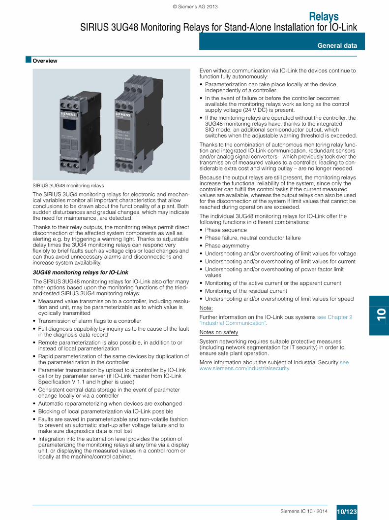
RelaysSIRIUS 3UG48 Monitoring Relays for Stand-Alone Installation for IO-Link
10/123Siemens IC 10 · 2014
General data
10
■ Overview
SIRIUS 3UG48 monitoring relays
The SIRIUS 3UG4 monitoring relays for electronic and mechan-ical variables monitor all important characteristics that allow conclusions to be drawn about the functionality of a plant. Both sudden disturbances and gradual changes, which may indicate the need for maintenance, are detected.
Thanks to their relay outputs, the monitoring relays permit direct disconnection of the affected system components as well as alerting e.g. by triggering a warning light. Thanks to adjustable delay times the 3UG4 monitoring relays can respond very flexibly to brief faults such as voltage dips or load changes and can thus avoid unnecessary alarms and disconnections and increase system availability.
3UG48 monitoring relays for IO-Link
The SIRIUS 3UG48 monitoring relays for IO-Link also offer many other options based upon the monitoring functions of the tried-and-tested SIRIUS 3UG4 monitoring relays:• Measured value transmission to a controller, including resolu-
tion and unit, may be parameterizable as to which value is cyclically transmitted
• Transmission of alarm flags to a controller• Full diagnosis capability by inquiry as to the cause of the fault
in the diagnosis data record• Remote parameterization is also possible, in addition to or
instead of local parameterization• Rapid parameterization of the same devices by duplication of
the parameterization in the controller• Parameter transmission by upload to a controller by IO-Link
call or by parameter server (if IO-Link master from IO-Link Specification V 1.1 and higher is used)
• Consistent central data storage in the event of parameter change locally or via a controller
• Automatic reparameterizing when devices are exchanged• Blocking of local parameterization via IO-Link possible• Faults are saved in parameterizable and non-volatile fashion
to prevent an automatic start-up after voltage failure and to make sure diagnostics data is not lost
• Integration into the automation level provides the option of parameterizing the monitoring relays at any time via a display unit, or displaying the measured values in a control room or locally at the machine/control cabinet.
Even without communication via IO-Link the devices continue to function fully autonomously:• Parameterization can take place locally at the device,
independently of a controller.• In the event of failure or before the controller becomes
available the monitoring relays work as long as the control supply voltage (24 V DC) is present.
• If the monitoring relays are operated without the controller, the 3UG48 monitoring relays have, thanks to the integrated SIO mode, an additional semiconductor output, which switches when the adjustable warning threshold is exceeded.
Thanks to the combination of autonomous monitoring relay func-tion and integrated IO-Link communication, redundant sensors and/or analog signal converters – which previously took over the transmission of measured values to a controller, leading to con-siderable extra cost and wiring outlay – are no longer needed.
Because the output relays are still present, the monitoring relays increase the functional reliability of the system, since only the controller can fulfill the control tasks if the current measured values are available, whereas the output relays can also be used for the disconnection of the system if limit values that cannot be reached during operation are exceeded.
The individual 3UG48 monitoring relays for IO-Link offer the following functions in different combinations:• Phase sequence• Phase failure, neutral conductor failure• Phase asymmetry• Undershooting and/or overshooting of limit values for voltage• Undershooting and/or overshooting of limit values for current• Undershooting and/or overshooting of power factor limit
values• Monitoring of the active current or the apparent current• Monitoring of the residual current• Undershooting and/or overshooting of limit values for speed
Note:
Further information on the IO-Link bus systems see Chapter 2 "Industrial Communication".
Notes on safety
System networking requires suitable protective measures (including network segmentation for IT security) in order to ensure safe plant operation.
More information about the subject of Industrial Security see www.siemens.com/industrialsecurity.
SIRIUS_IC10_chap10_English_2014.book Seite 123 Freitag, 10. Januar 2014 12:08 12
© Siemens AG 2013

RelaysSIRIUS 3UG48 Monitoring Relays for Stand-Alone Installation for IO-Link
General data
10/124 Siemens IC 10 · 2014
10
Use of conventional monitoring relays Monitoring relays for IO-Link
Notes:
Devices required for the communication via IO-Link:• Any controller that supports the IO-Link (e.g. ET 200S
with CPU or S7-300 plus ET 200S distributed I/O, see Catalog ST 70 "SIMATIC Products for Totally Integrated Automation")
• IO-Link master (IO-Link master 4SI IO-Link or 4SI SIRIUS inter-face module, which can connect all SIRIUS IO-Link devices to a controller, see Chapter 2 "Industrial Communication")
Each monitoring relay requires an IO-Link channel.
Article No. scheme
Note:
The Article No. scheme is presented here merely for information purposes and for better understanding of the logic behind the article numbers.
For your orders, please use the article numbers quoted in the catalog in the Selection and ordering data.
3
1 2
Feeder
PLC
Motor
3UG46monitoring relay
3UG46monitoring relay
3UG46monitoring relay
Analog signal
converter
Current transfor-
mers
Autonomous operation without PLC
Signaling of limit value violation plus measurement data transmission to PLC
Signaling of limit value violation to PLC
1
23
IC01_00003
2
1
1
PLC
IO-Link master
3UG48monitoring relay
3UG48monitoring relay
3UG48monitoring relay Feeder
Autonomous operation without PLC
Signaling of limit value violation plus measurement data transmission to PLC
2
Motor
1
IC01_00004
IO-Link
Digit of the Article No. 1st - 3rd 4th 5th 6th 7th 8th 9th 10th 11th 12th
@@@ @ @ @ @ – @ @ @ @ @
Monitoring relays 3 U G
Generation @
Type of setting @
Functions @ @
Connection methods @
Contacts @
Supply voltage @
Signal type of the control supply voltage @
Special version @
Example 3 U G 4 8 1 5 – 1 A A 4 0
SIRIUS_IC10_chap10_English_2014.book Seite 124 Freitag, 10. Januar 2014 12:08 12
© Siemens AG 2013

RelaysSIRIUS 3UG48 Monitoring Relays for Stand-Alone Installation for IO-Link
10/125Siemens IC 10 · 2014
General data
10
■ Benefits
• Simple cyclical transmission of the current measured values, relay switching states and events to a controller
• Remote parameterization• Automatic reparameterizing when devices are exchanged• Simple duplication of identical or similar parameterizations• Reduction of control current wiring • Elimination of testing costs and wiring errors• Reduction of configuration work• Integration in TIA means clear diagnostics if a fault occurs• Cost saving and space saving in control cabinet due to the
elimination of AI and IO modules as well as analog signal con-verters and duplicated sensors
Advantages through energy efficiency
Overview of the energy management process
We offer you a unique portfolio for industrial energy manage-ment, using an energy management system that helps to opti-mally define your energy needs. We split up our industrial energy management into three phases – identify, evaluate, and realize – and we support you with the appropriate hardware and software solutions in every process phase.
The innovative SIRIUS industrial controls products can also make a major contribution to the energy efficiency of a plant (www.siemens.com/sirius/energysaving).
The 3UG48 monitoring relays for IO-Link contribute to the energy efficiency throughout the plant as follows:• Shutdown in the event of no-load operation
(e.g. pump no-load operation)• Reactive-power compensation by means of power factor
monitoring• Load shedding of predefined loads in the event of current
overshoots
■ Application
The use of SIRIUS monitoring relays for IO-Link is particularly recommended for machines and plant in which these relays, in addition to their monitoring function, are to be connected to the automation level for the rapid, simple and fault-free provision of the current measured values and/or for remote parameterization.
The monitoring relays can either relieve the controller of monitor-ing tasks or, as a second monitoring entity in parallel to and in-dependent of the controller, increase the reliability in the process or in the system. In addition, the elimination of AI and IO modules allows the width of the controller to be reduced despite signifi-cantly expanded functionality.
IC01
_002
44
SIRIUS_IC10_chap10_English_2014.book Seite 125 Freitag, 10. Januar 2014 12:08 12
© Siemens AG 2013

RelaysSIRIUS 3UG48 Monitoring Relays for Stand-Alone Installation for IO-Link
General data
10/126 Siemens IC 10 · 2014
10
■ Technical specifications
■ More information
Manual "3UG48/3RR24 Monitoring Relays for IO-Link" see http://support.automation.siemens.com/WW/view/en/54375430.
Notes on safety
System networking requires suitable protective measures (including network segmentation for IT security) in order to ensure safe plant operation.
More information about the subject of Industrial Security see www.siemens.com/industrialsecurity.
Type 3UG48General technical specificationsDimensions (W x H x D)
• For 3 terminal blocks- Screw terminals mm 22.5 x 92 x 91- Spring-type terminals mm 22.5 x 94 x 91
• For 4 terminal blocks- Screw terminals mm 22.5 x 103 x 91- Spring-type terminals mm 22.5 x 103 x 91
Permissible ambient temperature• During operation °C -25 ... +60
Connection type Screw terminals
• Terminal screw M3 (for standard screwdriver, size 2 and Pozidriv 2)• Solid mm2 1 x (0.5 ... 4), 2 x (0.5 ... 2.5)• Finely stranded with end sleeve mm2 1 x (0.5 ... 2.5), 2 x (0.5 ... 1.5)• AWG cables, solid or stranded AWG 2 x (20 ... 14)• Tightening torque Nm 0.8 … 1.2
Connection type Spring-type terminals
• Solid mm2 2 x (0.25 ... 1.5)• Finely stranded, with end sleeves acc. to DIN 46228 mm2 2 x (0.25 ... 1.5)• Finely stranded mm2 2 x (0.25 ... 1.5)• AWG cables, solid or stranded AWG 2 x (24 ... 16)
W
H
D
SIRIUS_IC10_chap10_English_2014.book Seite 126 Freitag, 10. Januar 2014 12:08 12
© Siemens AG 2013
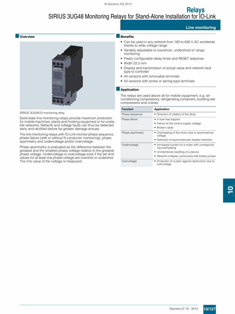
RelaysSIRIUS 3UG48 Monitoring Relays for Stand-Alone Installation for IO-Link
10/127Siemens IC 10 · 2014
Line monitoring
10
■ Overview
SIRIUS 3UG4815 monitoring relay
Solid-state line monitoring relays provide maximum protection for mobile machines, plants and hoisting equipment or for unsta-ble networks. Network and voltage faults can thus be detected early and rectified before far greater damage ensues.
The line monitoring relays with IO-Link monitor phase sequence, phase failure (with or without N conductor monitoring), phase asymmetry and undervoltage and/or overvoltage.
Phase asymmetry is evaluated as the difference between the greatest and the smallest phase voltage relative to the greatest phase voltage. Undervoltage or overvoltage exist if the set limit values for at least one phase voltage are overshot or undershot. The rms value of the voltage is measured.
■ Benefits
• Can be used in any network from 160 to 630 V AC worldwide thanks to wide voltage range
• Variably adjustable to overshoot, undershoot or range monitoring
• Freely configurable delay times and RESET response• Width 22.5 mm• Display and transmission of actual value and network fault
type to controller• All versions with removable terminals• All versions with screw or spring-type terminals
■ Application
The relays are used above all for mobile equipment, e.g. air conditioning compressors, refrigerating containers, building site compressors and cranes.
Function Application
Phase sequence • Direction of rotation of the drive
Phase failure • A fuse has tripped
• Failure of the control supply voltage
• Broken cable
Phase asymmetry • Overheating of the motor due to asymmetrical voltage
• Detection of asymmetrically loaded networks
Undervoltage • Increased current on a motor with correspond-ing overheating
• Unintentional resetting of a device
• Network collapse, particularly with battery power
Overvoltage • Protection of a plant against destruction due to overvoltage
SIRIUS_IC10_chap10_English_2014.book Seite 127 Freitag, 10. Januar 2014 12:08 12
© Siemens AG 2013

RelaysSIRIUS 3UG48 Monitoring Relays for Stand-Alone Installation for IO-Link
Line monitoring
10/128 Siemens IC 10 · 2014
10
■ Technical specifications
3UG4815/3UG4816 monitoring relays
The 3UG4815 and 3UG4816 line monitoring relays have a wide voltage range input and are supplied with power through IO-Link or from an external 24 V DC source.
The device is equipped with a display and is parameterized using three buttons. The 3UG4815 monitoring relay monitors three-phase networks with regard to phase sequence, phase failure, phase asymmetry, undervoltage and overvoltage. The 3UG4816 monitoring relay monitors the neutral conductor as well. The hysteresis is adjustable from 1 to 20 V.
The device has two separately adjustable delay times for over-voltage and undervoltage and for line stabilization. If the direc-tion of rotation is incorrect or a phase fails, the device switches off immediately. Thanks to a special measuring method, a phase failure is reliably detected in spite of the wide voltage range from and potentially high feedback through the load.
The 3UG4815 and 3UG4816 monitoring relays can be operated on the basis of either the open-circuit or closed-circuit principle and with Manual or Auto RESET.
If Manual RESET is selected in the menu (Memory = Yes), the switching relay remains in its current switching state and the current measured value and the symbol for undershooting and overshooting continues to flash, even when the measured vari-able reaches a permissible value again. This stored fault status can be reset by simultaneously pressing the UP▲ or DOWN▼ key for 2.5 s.
With Manual RESET through IO-Link it is possible in addition to set whether error signals are to be deleted when the control sup-ply voltage is switched off and on (as remote RESET) or whether the signals are to be permanently saved even in a voltage failure, with confirmation possible only through local RESET or via IO-Link.
With the closed-circuit principle selected
Wrong phase sequence
Phase failure
Undervoltage
Overvoltage
IC01
_000
05L3-L2-L111/1411/12
11/1411/12
L1-L2-L3L1-L2-L3-N
L2-L3L1-L2-L3
L1-L2-L3L1-L2-L3-N
IC01
_000
06IC
01_0
0007
< U
L+/L-
Q offQ on
11/1211/14
Ux-y
DelaystDelay
Hysteresis
> U
L+/L-
Q offQ on
11/1211/14
Ux-y
DelaystDelay
Hysteresis
IC01
_000
08
Type 3UG4815, 3UG4816General technical specificationsRated insulation voltage UiPollution degree 2Overvoltage category III acc. to VDE 0110
V 690
Rated impulse withstand voltage Uimp kV 6Control circuit
Load capacity of the output relay
• Conventional thermal current Ith A 5
Rated operational current Ie at
• AC-15/24 ... 400 V A 3• DC-13 at
- 24 V A 1- 125 V A 0.2- 250 V A 0.1
Minimum contact load at 17 V DC mA 5
Electrical endurance AC-15 Million operating cycles 0.1
Mechanical endurance Million operating cycles 10
SIRIUS_IC10_chap10_English_2014.book Seite 128 Freitag, 10. Januar 2014 12:08 12
© Siemens AG 2013

RelaysSIRIUS 3UG48 Monitoring Relays for Stand-Alone Installation for IO-Link
Line monitoring
10/129Siemens IC 10 · 2014* You can order this quantity or a multiple thereof.Illustrations are approximate
10
Circuit diagrams
■ Selection and ordering data • Adjustable via IO-Link and locally, with illuminated LCD• Power supply with 24 V DC via IO-Link or
external auxiliary voltage• Auto or Manual RESET• Open or closed-circuit principle• 1 CO contact, 1 semiconductor output (in SIO mode)
PU (UNIT, SET, M) = 1PS* = 1 unitPG = 41H
✓ Function available
1) Absolute limit values.2) In SIO mode.
For accessories see page 10/146.
Note:
It is not necessary to protect the measuring circuit for device protection. The protective device for line protection depends on the cross-section used.
3UG4815 3UG4816
L3 11
12 14
L2L1
IO-Link
L+C/QL-
IC01_00009
L3 11
12 14
L2L1N
IO-Link
L+C/QL-
IC01_00010
Adjust-able hysteresis
Under-voltage detection
Over-voltage detection
Stabilization time adjustablestDEL
Tripping delay time adjustable Del
Version of auxiliary contacts
Measurable mains voltage1)
DT Screw terminals DT Spring-type terminals
V s s V ACArticle No. Price
per PUArticle No. Price
per PUMonitoring of phase sequence, phase failure, phase asymmetry, overvoltage and undervoltage 1 ... 20 ✓ ✓ 0.1 … 999.9 0.1 … 999.9 1 CO + 1 Q 2) 160 … 690 A 3UG4815-1AA40 A 3UG4815-2AA40
Monitoring of phase sequence, phase and N conductor failure, phase asymmetry, overvoltage and undervoltage 1 ... 20 ✓ ✓ 0.1 … 999.9 0.1 … 999.9 1 CO + 1 Q 2) 90 … 400
against NA 3UG4816-1AA40 A 3UG4816-2AA40
3UG4815-1AA40 3UG4816-1AA40 3UG4815-2AA40 3UG4816-2AA40
SIRIUS_IC10_chap10_English_2014.book Seite 129 Freitag, 10. Januar 2014 12:08 12
© Siemens AG 2013