Embed Size (px)
Citation preview

SIPROTEC 5 V1.1High-Voltage Bay Control Unit 6MD85/86
Technical Data
Extract from manual C53000-G5040-C015-1, chapter 11
Energy Automation

NOTEFor your own safety, please observe the warnings and safety instructions contained in this manual.
Disclaimer of LiabilityThis document has been subjected to rigorous technical review before being published. It is revised at regular intervals, and any modifications and amendments are included in the subsequent issues. The content of this doc-ument has been compiled for information purposes only. Although Siemens AG has made best efforts to keep the document as precise and up-to-date as possible, Siemens AG shall not assume any liability for defects and damage which result through use of the information contained herein.This content does not form part of a contract or of business relations; nor does it change these. All obligations of Siemens AG are stated in the relevant contractual agreements.Siemens AG reserves the right to revise this document from time to time.Document version: 01Release status: 03.2012Version of the product described: V 1.1
CopyrightCopyright � Siemens AG 2012 All rights reserved.The disclosure, duplication, distribution and editing of this document, or utili-zation and communication of the content are not permitted, unless autho-rized in writing. All rights, including rights created by patent grant or registra-tion of a utility model or a design, are reserved.Registered TrademarksSIPROTEC � , DIGSI �, SIGUARD �, SIMEAS � and SICAM � are registered trademarks of Siemens AG. Any unauthorized use is illegal. All other desig-nations in this document can be trademarks whose use by third parties for their own purposes can infringe the rights of the owner.

SIPROTEC High-Voltage Bay Controller, ManualC53000-G5040-C015-1, Release 03.2012
3
Preface
Purpose of the manual
This manual describes the functions of SIPROTEC 5 high voltage bay controllers.
Target audience
Protection system engineers, commissioning engineers, persons entrusted with the setting, testing and main-tenance of automation, selective protection and control equipment, and operating personnel in electrical instal-lations and power plants.
Scope
This manual is valid for the SIPROTEC 5 device family, configuration version V1.0
Further documentation
[DwPrefDM-110203-enUS-01.tif]

Preface
SIPROTEC High-Voltage Bay Controller, ManualC53000-G5040-C015-1, Release 03.2012
4
• Device manuals
Device manuals describe the functions and applications of a specific SIPROTEC 5 device. The printed manual and the device's online help have the same informational structure.
• Hardware manual
The hardware manual describes the hardware components and device combinations of the SIPROTEC 5 device family.
• Operating manual
The operating manual describes the basic principles and procedures for operating and assembling the devices of the SIPROTEC 5 range.
• Communications protocol manuals
The communications protocol manuals include a description of specific protocols for communication within the SIPROTEC 5 family and to higher-level control centers.
• Product information
The product information includes general information about device installation, technical data, limit values for input and output modules, and conditions when preparing for operation. This document is delivered with each SIPROTEC 5 device.
• DIGSI 5 online help
The DIGSI 5 online help contains a help package for DIGSI and CFC.
The help package for DIGSI 5 includes a description of the basic operation of software, the DIGSI princi-ples and editors. The help package for CFC includes an introduction to CFC programming, basic exam-ples for CFC management, and a reference chapter with all CFC modules available for the SIPROTEC 5 family.
• SIPROTEC 5/DIGSI 5 Tutorial
The tutorial on the DVD contains brief information about important product features, more detailed infor-mation about the individual technical areas, as well as operating sequences with tasks based on practical operation and a brief explanation.
• System catalog
The system catalog describes the SIPROTEC 5 system features.
• Device catalogs
The device catalogs describe device-specific features such as functional scope, hardware and applica-tions.
Indication of Conformity
[ScCEsign-080211-xxXX-01.tif]
This product complies with the directive of the Council of the European Communities on harmonization of the laws of the Member States relating to electromagnetic com-patibility (EMC Council Directive 2004/108/EC) and concerning electrical equipment for use within specified voltage limits (Low Voltage Directive 2006/95/EC). This conformity has been proved by tests performed according to the Council Directive in accordance with the generic standards EN 61000-6-2 and EN 61000-6-4 (for EMC directive) and with the standard EN 60255-27 (for Low Voltage Directive) by Siemens AG. The device is designed and manufactured for application in an industrial environment. The product conforms with the international standards of IEC 60255 and the German standard VDE 0435.

Preface
SIPROTEC High-Voltage Bay Controller, ManualC53000-G5040-C015-1, Release 03.2012
5
Other Standards
IEEE Std C 37.90
The technical data of the product is approved in accordance with UL.
File E194016
[ScPrefUL-070211-xxXX-01.tif]
Additional Support
For questions about the system, please contact your Siemens sales partner.
Support
Our Customer Support Center provides a 24-hour service.
Phone: +49 (1805) 24-7000
Fax: +49 (1805) 24-2471
Email: [email protected]
Training Courses
Inquiries regarding individual training courses should be addressed to our Training Center:
Siemens AG
Siemens Power Academy
Humboldtstrasse 59
90459 Nuremberg
Phone: +49 (911) 433-7415
Fax: +49 (911) 433-5482
Email: [email protected]
Internet: http://www.siemens.com/energy/power-academy
.

Preface
SIPROTEC High-Voltage Bay Controller, ManualC53000-G5040-C015-1, Release 03.2012
6
Safety Information
This manual is not a complete index of all safety measures required for operation of the equipment (module, device). However, it comprises important information that must be noted for purposes of personal safety, as well as in order to avoid material damage. Information is highlighted and illustrated as follows according to the degree of danger.
DANGERDANGER means that death or severe injury will result if the measures specified are not taken.
✧ Comply with all instructions, in order to avoid death or severe injuries.
WARNINGWARNING means that death or severe injury may result if the measures specified are not taken.
✧ Comply with all instructions, in order to avoid death or severe injuries.
CAUTIONCAUTION means that medium-severe or slight injuries can occur if the specified measures are not taken.
✧ Comply with all instructions, in order to avoid medium-severe or slight injuries.
NOTICENOTICE means that material damage can result if the measures specified are not taken.
✧ Comply with all instructions, in order to avoid material damage.
NOTE
Important information about the product, product handling, or a certain section of the documentation, which must be given particular attention.
.

Preface
SIPROTEC High-Voltage Bay Controller, ManualC53000-G5040-C015-1, Release 03.2012
7
Qualified Electrical Engineering Personnel
Only qualified electrical engineering personnel may commission and operate the equipment (module, device) described in this document. Qualified electrical engineering personnel in the sense of this manual are people who can demonstrate technical qualifications as electrical technicians. These persons may commission, iso-late, ground and label devices, systems and circuits according to the standards of safety engineering.
Use as Prescribed
The equipment (device, module) may only be used for such applications as set out in the catalogs and the tech-nical description, and only in combination with third-party equipment recommended and approved by Siemens.
Problem-free and safe operation of the product depends on the following:
• Proper transport
• Proper storage, setup, and installation
• Proper operation and maintenance
When electrical equipment is operated, hazardous voltages are inevitably present in certain parts. If proper action is not taken, death, severe injury, or property damage can result.
• The equipment must be grounded at the grounding terminal before any connections are made.
• All circuit components connected to the power supply may be subject to dangerous voltage.
• Hazardous voltages may be present in equipment even after the supply voltage has been disconnected (capacitors can still be charged).
• Equipment with exposed current transformer circuits must not be operated. Prior to disconnecting the equipment, ensure that the current transformer circuits are short-circuited.
• The limit values stated in the document may not be exceeded. This must also be considered during testing and commissioning.

Preface
SIPROTEC High-Voltage Bay Controller, ManualC53000-G5040-C015-1, Release 03.2012
8
SIPROTEC High-Voltage Bay Controller, ManualC53000-G5040-C015-1, Release 03.2012
697
11 Technical Data
11.1 General Device Data 699
11.2 Date and Time Synchronization 705
11.3 Automatic Reclosing 706
11.4 Phasor Measurement Unit 707
11.5 External Trip 708
11.6 Definite Time-Overcurrent Protection, Phases 709
11.7 Inverse Time-Overcurrent Protection, Phases 710
11.8 Overcurrent Protection, Phases with User-Defined Characteristic 717
11.9 Definite Time-Overcurrent Protection, Ground 718
11.10 Inverse Time-Overcurrent Protection, Ground 719
11.11 Overcurrent Protection, Ground with User-Defined Characteristic Curve 726
11.12 Instantaneous High-Current Tripping 727
11.13 Overvoltage Protection with 3-Phase Voltage 728
11.14 Overvoltage Protection with Positive-Sequence Voltage 729
11.15 Overvoltage Protection with Any Voltage 730
11.16 Overfrequency Protection 731
11.17 Underfrequency Protection 732
11.18 Instantaneous Tripping at Switch onto Fault 733
11.19 Circuit-Breaker Failure Protection 734
11.20 Negative-Sequence Protection with Definite Time Characteristic Curve 735
11.21 Thermal Overload Protection 736
11.22 Inrush-Current Detection 738
11.23 Synchronization Function 739
11.24 Broken-Wire Detection 741
11.25 Current-Balance Supervision 742
11.26 Voltage-Balance Supervision 743
11.27 Current-Sum Supervision 744
11.28 Voltage-Sum Supervision 745
11.29 Current Phase-Rotation Supervision 746

Technical Data
SIPROTEC High-Voltage Bay Controller, ManualC53000-G5040-C015-1, Release 03.2012
698
11.30 Voltage Phase-Rotation Supervision 747
11.31 Trip-Circuit Supervision 748
11.32 Supervision of Device-Internal Analog-Digital Converters 749
11.33 Operational Measured Values 750
11.34 Energy Values 752
Technical Data11.1 General Device Data
SIPROTEC High-Voltage Bay Controller, ManualC53000-G5040-C015-1, Release 03.2012
699
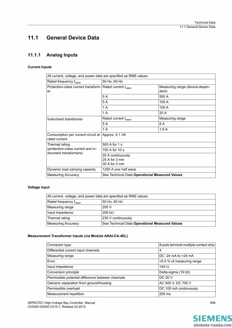
11.1 General Device Data
11.1.1 Analog Inputs
Current Inputs
Voltage Input
Measurement Transformer Inputs (via Module ANAI-CA-4EL)
All current, voltage, and power data are specified as RMS values.Rated frequency frated 50 Hz, 60 HzProtection-class current transform-er
Rated current Irated Measuring range (device-depen-dent)
5 A 500 A5 A 100 A1 A 100 A1 A 20 A
Instrument transformer Rated current Irated Measuring range5 A 8 A1 A 1.6 A
Consumption per current circuit at rated current
Approx. 0.1 VA
Thermal rating(protection-class current and in-strument transformers)
500 A for 1 s150 A for 10 s20 A continuously25 A for 3 min30 A for 2 min
Dynamic load carrying capacity 1250 A one half waveMeasuring Accuracy See Technical Data Operational Measured Values
All current, voltage, and power data are specified as RMS values.Rated frequency frated 50 Hz, 60 HzMeasuring range 200 VInput impedance 200 k�Thermal rating 230 V continuouslyMeasuring Accuracy See Technical Data Operational Measured Values
Connector type 8-pole terminal multiple contact stripDifferential current input channels 4Measuring range DC -24 mA to +24 mAError <0.5 % of measuring rangeInput impedance 140 �Conversion principle Delta-sigma (16 bit)Permissible potential difference between channels DC 20 VGalvanic separation from ground/housing AC 500 V, DC 700 V Permissible overload DC 100 mA continuouslyMeasurement repetition 200 ms

Technical Data11.1 General Device Data
SIPROTEC High-Voltage Bay Controller, ManualC53000-G5040-C015-1, Release 03.2012
700
11.1.2 Supply Voltage.
11.1.3 Binary Inputs.
Integrated Power SupplyThe following modules contain a power supply:PS201 – Power supply of the base module and of the 1st device rowCB202 – Plug-in module assembly with integrated power supply, for example to accommodate communication modulesAuxiliary rated voltage VH DC 24 V/DC 48 V DC 60 V/DC 110 V/DC 125 V/
DC 220 V/DC 250 V orAC 115 V/AC 230 V, 50 Hz/60 Hz
Permissible voltage ranges DC 19 V to 60 V DC 48 V to 300 VDC 80 V to 265 V
Overvoltage category, IEC 60255-27 IIISuperimposed alternating voltage, peak-to-peak, IEC 60255-11 � 15 % of the DC auxiliary rated voltage (applies only to direct voltage)Inrush current � 18 ARecommended external protection Miniature circuit breaker 6 A, charac-
teristic C according to IEC 60898Internal fuse 2 A time-lag, AC 250 V, DC 300 V, UL
recognizedSIBA type 179200 or Schurter type SPT 5x20
Power Consumption (Life Relay Active) DC AC 230 V/50 Hz AC 115 V/50 Hz1/3 base module without plug-in modules
13 W 33 VA 24 VA
1/6 expansion module 3 W 6 VA 6 VA1/6 plug-in module assembly without plug-in modules
3.5 W 14 VA 7 VA
Plug-in module for base module or plug-in module assembly (for ex-ample, communication module)
< 5 W < 6 VA < 6 VA
Stored-energy time on outage or short circuit of the auxiliary voltage
At least 50 ms
Rated voltage range DC 24 V to 250 V (bipolar)Current consumption, picked up Approx. DC 0.4 mA (independently of the operating voltage) Pickup time Approx. 3 msDropout time Approx. 4 msSwitching thresholds Adjustable with DIGSI 5
Range 1 for 24 V, 48 V, and 60 VOperating voltage
DC Vlow � 10 VDC Vhigh � 19 V
Range 2 for 110 V and 125 V Operating voltage
DC Vlow � 44 VDC Vhigh � 88 V
Range 3 for 220 V and 250 V Operating voltage
DC Vlow � 88 VDC Vhigh � 176 V
Maximum permitted voltage DC 300 VThe binary inputs contain interference suppression capacitors. In order to ensure EMC, use the terminals shown in the terminal diagrams/connection diagrams to connect the binary inputs to the common potential.

Technical Data11.1 General Device Data
SIPROTEC High-Voltage Bay Controller, ManualC53000-G5040-C015-1, Release 03.2012
701
11.1.4 Relay Outputs
Standard Relay (Type S)
1. OOT (Output Operating Time) additional delay of the output medium used
Fast Relay (Type F)
1. OOT (Output Operating Time) additional delay of the output medium used
Switching capacity On: 1000 W/VAOff: 30 VA; 40 W ohmic; 25 W/VA at L/R � 40 ms
AC and DC contact voltage 250 VPermissible current per contact (continuous) 5 APermissible current per contact (switching on and holding)
30 A for 1 s (make contact)
Short-time current across closed contact 250 A for 30 msTotal permissible current for contacts connected to common potential
5 A
Switching time (OOT1) � 10 msRated data of the output contacts DC 24 V, 8 A, general purpose
DC 48 V, 0.8 A, general purposeDC 240 V, 0.1 A, general purposeAC 240 V, 5 A, general purposeAC 120 V, 248.7 WAC 250 V, 373 WB300R300
Interference suppression capacitors across the con-tacts
4.7 nF, � 20 %, AC 250 V
Switching capacity On: 1000 W/VAOff: 30 VA; 40 W ohmic; 25 W/VA at L/R � 40 ms
AC and DC contact voltage 250 VPermissible current per contact (continuous) 5 APermissible current per contact (switching on and holding)
30 A for 1 s (make contact)
Short-time current across closed contact 250 A for 30 msTotal permissible current for contacts connected to common potential
5 A
Switching time (OOT1) � 5 msRated data of the output contacts AC 120 V, 8.5 A, general purpose
AC 277 V, 6 A, general purposeAC 277 V, 522.2 WAC 347 V, 4.5 A, general purposeB300R300
Interference suppression capacitors across the con-tacts
4.7 nF, � 20 %, AC 250 V

Technical Data11.1 General Device Data
SIPROTEC High-Voltage Bay Controller, ManualC53000-G5040-C015-1, Release 03.2012
702
High-Speed Relay with Semiconductor Acceleration (Type HS)
1. OOT (Output Operating Time) additional delay of the output medium used
Switching capacity On/Off: 1000 W/VAContact voltage AC 200 V, DC 250 VPermissible current per contact (continuous) 5 APermissible current per contact (switching on and holding)
30 A for 1 s (make contact)
Short-time current across closed contact 250 A for 30 msTotal permissible current for contacts connected to common potential
5 A
Switching time (OOT1) � 1 msRated data of the output contacts B150
Q300

Technical Data11.1 General Device Data
SIPROTEC High-Voltage Bay Controller, ManualC53000-G5040-C015-1, Release 03.2012
703
11.1.5 Design Data
Masses
Base-Module Dimensions
Dimensions of the Device Rows
Expansion-Module Dimensions
Device SizeWeight
Type of construction 1/3 1/2 2/3 5/6 1/1Flush-mounting device 4.8 kg 8.1 kg 11.4 kg 14.7 kg 18.0 kgSurface-mounting device with in-tegrated on-site operation panel
7.8 kg 12.6 kg 17.4 kg 22.2 kg 27.0 kg
Surface-mounting device with de-tached on-site operation panel
5.1 kg 8.7 kg 12.3 kg 15.9 kg 19.5 kg
Size WeightDetached on-site operation panel 1/3 1.9 kgDetached on-site operation panel 1/6 1.1 kg
Type of Construction (Maximum Dimensions)
Width x Height x Depth in mm (in inches)
Flush-mounting device 145 x 268 x 228.5 (5.71 x 10.55 x 9)Surface-mounting device with inte-grated on-site operation panel
145 x 314 x 337 (5.71 x 12.36 x 13.27)
Surface-mounting device with de-tached on-site operation panel
145 x 314 x 230 (5.71 x 12.36 x 9.06)
Type of Construction (Maximum Dimensions)
Width x Height x Depth in mm (in inches)
Type of construction 1/3 1/2 2/3 5/6 1/1Flush-mounting device 145 x 268 x
228.5 (5.71 x 10.55 x 9)
220 x 268 x 228.5 (8.66 x 10.55 x 9)
295 x 268 x 228.5 (11.61 x 10.55 x 9)
370 x 268 x 228.5 (14.57 x 10.55 x 9)
445 x 268 x 228.5 (17.52 x 10.55 x 9)
Surface-mounting device with inte-grated on-site operation panel
145 x 314 x 337 (5.71 x 12.36 x 13.27)
220 x 314 x 337 (8.66 x 12.36 x 13.27)
295 x 314 x 337 (11.61 x 12.36 x 13.27)
370 x 314 x 337 (14.57 x 12.36 x 13.27)
445 x 314 x 337 (17.52 x 12.36 x 13.27)
Surface-mounting device with de-tached on-site operation panel
145 x 314 x 230 (5.71 x 12.36 x 9.06)
220 x 314 x 230 (8.66 x 12.36 x 9.06)
295 x 314 x 230 (11.61 x 12.36 x 9.06)
370 x 314 x 230 (14.57 x 12.36 x 9.06)
445 x 314 x 230 (17.52 x 12.36 x 9.06)
Type of Construction (Maximum Dimensions)
Width x Height x Depth in mm (in inches)
Flush-mounting device 75 x 268 x 228.5 (2.95 x 10.55 x 9)Surface-mounting device with inte-grated on-site operation panel
75 x 314 x 337 (2.95 x 12.36 x 13.27)
Surface-mounting device with de-tached on-site operation panel
75 x 314 x 230 (2.95 x 12.36 x 9.06)

Technical Data11.1 General Device Data
SIPROTEC High-Voltage Bay Controller, ManualC53000-G5040-C015-1, Release 03.2012
704
Minimum Bending Radii of the Connecting Cables between the On-Site Operation Panel and the Base Module
Degree of Protection According to IEC 60529
UL Note
Tightening Torques for Terminal Screws
Fiber-optic cable R = 50 mm (1.97 in)Pay attention to the length of the cable protection sleeve, which you must also include in calculations.
D-Sub cable R = 50 mm (1.97 in) (minimum bending radius)
For the equipment in the surface-mounting housing IP50For the equipment in the flush-mounting housing Front IP51
Rear panel IP50For operator protection IP2X for current terminals
IP1X for voltage terminalsDegree of pollution, IEC 60255-27 2
Type 1 if mounted into a door or front cover of an enclosure.
Type of Cable 1
1. Use copper cables only.
Current Terminal Voltage TerminalPower line with ring-type lug 2.7 Nm No ring-type lugStranded wires with bootlace fer-rules or pin-type lugs
2.7 Nm 1.0 Nm
Solid conductor, bare (2 mm2 (0.08 in2))
2.0 Nm 1.0 Nm

Technical Data11.2 Date and Time Synchronization
SIPROTEC High-Voltage Bay Controller, ManualC53000-G5040-C015-1, Release 03.2012
705
11.2 Date and Time Synchronization.
Date format DD.MM.YYYY (Europe)MM/DD/YYYY (USA)YYYY-MM-DD (China)
Time source 1, Time source 2 NoneIRIG BDCF 77PISNTPIEC 60870-5-103DNP3
Time zone 1, Time zone 2 LocalUTC
Fault indication after 0 s to 3 600 sTime zone and daylight saving time Transfer of PC settings
Manually setting the time zonesTime zone offset with respect to GMT -720 min to 840 minSwitching over to daylight saving time Active
InactiveBeginning of daylight saving time Input: Day and timeEnd of daylight saving time Input: Day and timeOffset daylight saving time -120 to 120 [steps of 15]

Technical Data11.3 Automatic Reclosing
SIPROTEC High-Voltage Bay Controller, ManualC53000-G5040-C015-1, Release 03.2012
706
11.3 Automatic Reclosing.
Function specifications Cyclic Automatic Reclosing FunctionAutomatic reclosing function with adaptive dead time (ADT)Operation with External Automatic Reclosing Function
Number of reclosings Max. 8, per individual parameterType (depending on the order varia-tion)
1-pole, 3-pole, or 1-/3-pole
Operating mode of the automatic reclosing function
With trip command, without action timeWith trip command, with action timeWith pickup, without action timeWith pickup, with action time
Reclaim time after reclosing 0.50 s to 300.00 s Increments of 0.01 sBlocking time after dynamic block-ing
0.5 s -
Blocking time after manual switch-ing
0.00 s to 300.00 s Increments of 0.01 s
Start supervision time 0.01 s to 300.00 s Increments of 0.01 sCircuit-breaker supervision time 0.01 s to 300.00 s Increments of 0.01 sEvolving-fault detection With trip command
With pickupReaction to evolving faults Blocks automatic reclosing function
Start, evolving fault, dead timeAction times (separated for all cycles)
0.00 s to 300.00 s or oo (ineffective)
Increments of 0.01 s
Dead times after trip command (separated for all types and all cycles)
0.00 s to 1 800.00 s or oo (ineffective)
Increments of 0.01 s
Dead time after evolving-fault de-tection (separated for all cycles)
0.00 s to 1 800.00 s Increments of 0.01 s
Synchrocheck after 3-pole dead time
NoneInternalExternal
Transmission delay, inter closing command
0.00 s to 300.00 s or oo (ineffective)
Increments of 0.01 s
Dead-line checking/reduced dead time
WithoutReduced dead time (RDT)Dead-line checking
Voltage-supervision warning time 0.10 s to 30.00 s Increments of 0.01 sLimiting value for error-free line 0.3 V to 340.0 V Increments of 0.1 VLimiting value for zero potential 0.3 V to 340.0 V Increments of 0.1 V

Technical Data11.4 Phasor Measurement Unit
SIPROTEC High-Voltage Bay Controller, ManualC53000-G5040-C015-1, Release 03.2012
707
11.4 Phasor Measurement Unit
Frequency
Magnitudes, Phase Angles
Frequency range 10 Hz to 80 HzAccuracy 5 mHz in a range from 0.7·frated to 1.2·frated
Accuracy for magnitude measurements 0.1 %Accuracy for phase-angle measurements 0.1 °

Technical Data11.5 External Trip
SIPROTEC High-Voltage Bay Controller, ManualC53000-G5040-C015-1, Release 03.2012
708
11.5 External Trip
Setting Values
Times
Tolerance
Tripping delay 0.00 s to 60.00 s Increments of 0.01 s
Tripping time with time delay = 0 ms - at initiation via binary input signal Approx. 5 ms + OOT 1.
1. OOT (Output Operating Time) additional delay of the output medium used, for example 5 ms with fast relays, see Section 11.1.4 Relay Outputs
Sequence tolerance for time delays 1 % of the setting value or 10 ms

Technical Data11.6 Definite Time-Overcurrent Protection, Phases
SIPROTEC High-Voltage Bay Controller, ManualC53000-G5040-C015-1, Release 03.2012
709
11.6 Definite Time-Overcurrent Protection, Phases
Setting Values
Times
Operating Ranges
Tolerances
Influencing Variables for the Thresholds
Method of measurement Fundamental frequencyRMS value
–
Threshold value For Irated = 1 A 0.030 A to 100.000 A Increments of 0.001 AFor Irated = 5 A 0.15 A to 500.00 A Increments of 0.01 A
Dropout ratio 0.90 to 0.99 Increments of 0.01Time delay 0.00 s to 60.00 s Increments of 0.01 sDropout delay 0.00 s to 60.00 s Increments of 0.01 s
Tripping time with time delay = 0 ms Approx. 25 ms + OOT 1 at 50 HzApprox. 22 ms + OOT at 60 Hz
1. OOT (Output Operating Time) additional delay of the output medium used, for example 5 ms with fast relays
Extension of the operate time during operation with Transformer inrush-current detection
Approx. 10 ms
Dropout time Approx. 20 ms + OOT
10 Hz to 80 Hz According to specified tolerancesOutside 10 Hz to 80 Hz Active
Currents, method of measurement = fundamental component
1 % of setting value or 5 mA (Irated = 1 A)or 25 mA (Irated = 5 A), (frated � 10 %)
Currents, method of measurement = RMS valueUp to 30th harmonic Up to 35th harmonic (33 % part of harmonic, referring to fundamental com-ponent)
1 % of setting value or 5 mA (Irated = 1 A)or 25 mA (Irated = 5 A), (frated � 10 %)2 % of setting value or 10 mA (Irated = 1 A)or 50 mA (Irated = 5 A), (frated � 10 %)
Time delays 1 % of the setting value or 10 ms
Transient excess pickup in method of measurement = fundamental frequency, for � > 100 ms (with complete unbalance)
< 5 %

Technical Data11.7 Inverse Time-Overcurrent Protection, Phases
SIPROTEC High-Voltage Bay Controller, ManualC53000-G5040-C015-1, Release 03.2012
710
11.7 Inverse Time-Overcurrent Protection, Phases
Setting Values
Operate Curves and Dropout-Time Characteristic Curves According to IEC
Method of measurement Fundamental frequencyRMS value
–
Threshold value For Irated = 1 A 0.030 A to 100.000 A Increments of 0.001 AFor Irated = 5 A 0.15 A to 500.00 A Increments of 0.01 A
Dropout Disk emulationInstantaneous
–
Time multiplier 0.05 to 15.00 Increments of 0.01
Extension of the operate time during operation with transformer inrush-current detection
Approx. 10 ms

Technical Data11.7 Inverse Time-Overcurrent Protection, Phases
SIPROTEC High-Voltage Bay Controller, ManualC53000-G5040-C015-1, Release 03.2012
711
[DwOCPki1-030311-enUS-01.tif]
Figure 11-1 Operate Curves and Dropout-Time Characteristic Curves According to IEC

Technical Data11.7 Inverse Time-Overcurrent Protection, Phases
SIPROTEC High-Voltage Bay Controller, ManualC53000-G5040-C015-1, Release 03.2012
712
[DwOCPki2-030311-enUS-01.tif]
Figure 11-2 Operate Curves and Dropout-Time Characteristic Curves According to IEC

Technical Data11.7 Inverse Time-Overcurrent Protection, Phases
SIPROTEC High-Voltage Bay Controller, ManualC53000-G5040-C015-1, Release 03.2012
713
Operate Curves and Dropout-Time Characteristic Curves According to ANSI/IEEE
[DwOCPka1-270112-enUS-01.tif]
Figure 11-3 Operate Curves and Dropout-Time Characteristic Curves According to ANSI/IEEE

Technical Data11.7 Inverse Time-Overcurrent Protection, Phases
SIPROTEC High-Voltage Bay Controller, ManualC53000-G5040-C015-1, Release 03.2012
714
[DwOCPka2-110611-enUS-01.tif]
Figure 11-4 Operate Curves and Dropout-Time Characteristic Curves According to ANSI/IEEE

Technical Data11.7 Inverse Time-Overcurrent Protection, Phases
SIPROTEC High-Voltage Bay Controller, ManualC53000-G5040-C015-1, Release 03.2012
715
[DwOCPka3-030311-enUS-01.tif]
Figure 11-5 Operate Curves and Dropout-Time Characteristic Curves According to ANSI/IEEE

Technical Data11.7 Inverse Time-Overcurrent Protection, Phases
SIPROTEC High-Voltage Bay Controller, ManualC53000-G5040-C015-1, Release 03.2012
716
[DwOCPka4-050711-enUS-01.tif]
Figure 11-6 Operate Curves and Dropout-Time Characteristic Curves According to ANSI/IEEE
Tolerances
Influencing Variables for the Thresholds
Currents, method of measurement = fundamental component
1 % of setting value or 5 mA (Irated = 1 A)or 25 mA (Irated = 5 A), (frated � 10 %)
Currents, method of measurement = RMS valueUp to 30th harmonic Up to 35th harmonic (33 % part of harmonic, referring to fundamental com-ponent)
1 % of setting value or 5 mA (Irated = 1 A)or 25 mA (Irated = 5 A), (frated � 10 %)2 % of setting value or 10 mA (Irated = 1 A)or 50 mA (Irated = 5 A), (frated � 10 %)
Operate time for 2 � I/I threshold value � 20 5 % of set point value or +2 % current tolerance or 30 ms
Dropout time for I/I threshold value � 0.90 5 % of set point value or +2 % current tolerance or 30 ms
Transient excess pickup in method of measurement = fundamental component, for � > 100 ms (with complete unbalance)
< 5 %
Technical Data11.8 Overcurrent Protection, Phases with User-Defined Characteristic
SIPROTEC High-Voltage Bay Controller, ManualC53000-G5040-C015-1, Release 03.2012
717
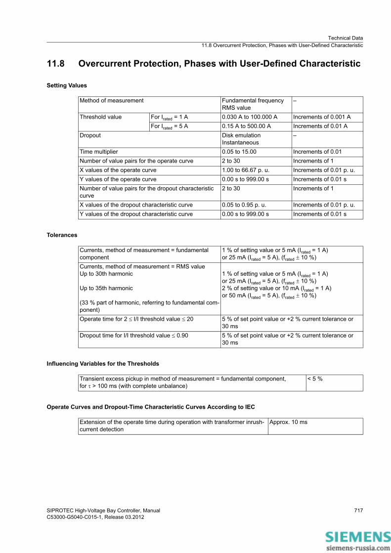
11.8 Overcurrent Protection, Phases with User-Defined Characteristic
Setting Values
Tolerances
Influencing Variables for the Thresholds
Operate Curves and Dropout-Time Characteristic Curves According to IEC
Method of measurement Fundamental frequencyRMS value
–
Threshold value For Irated = 1 A 0.030 A to 100.000 A Increments of 0.001 AFor Irated = 5 A 0.15 A to 500.00 A Increments of 0.01 A
Dropout Disk emulationInstantaneous
–
Time multiplier 0.05 to 15.00 Increments of 0.01Number of value pairs for the operate curve 2 to 30 Increments of 1X values of the operate curve 1.00 to 66.67 p. u. Increments of 0.01 p. u.Y values of the operate curve 0.00 s to 999.00 s Increments of 0.01 sNumber of value pairs for the dropout characteristic curve
2 to 30 Increments of 1
X values of the dropout characteristic curve 0.05 to 0.95 p. u. Increments of 0.01 p. u.Y values of the dropout characteristic curve 0.00 s to 999.00 s Increments of 0.01 s
Currents, method of measurement = fundamental component
1 % of setting value or 5 mA (Irated = 1 A)or 25 mA (Irated = 5 A), (frated � 10 %)
Currents, method of measurement = RMS valueUp to 30th harmonic Up to 35th harmonic (33 % part of harmonic, referring to fundamental com-ponent)
1 % of setting value or 5 mA (Irated = 1 A)or 25 mA (Irated = 5 A), (frated � 10 %)2 % of setting value or 10 mA (Irated = 1 A)or 50 mA (Irated = 5 A), (frated � 10 %)
Operate time for 2 � I/I threshold value � 20 5 % of set point value or +2 % current tolerance or 30 ms
Dropout time for I/I threshold value � 0.90 5 % of set point value or +2 % current tolerance or 30 ms
Transient excess pickup in method of measurement = fundamental component, for � > 100 ms (with complete unbalance)
< 5 %
Extension of the operate time during operation with transformer inrush-current detection
Approx. 10 ms

Technical Data11.9 Definite Time-Overcurrent Protection, Ground
SIPROTEC High-Voltage Bay Controller, ManualC53000-G5040-C015-1, Release 03.2012
718
11.9 Definite Time-Overcurrent Protection, Ground
Setting Values
Times
Operating Ranges
Tolerances
Influencing Variables for the Thresholds
Method of measurement Fundamental frequencyRMS value
–
Threshold value For Irated = 1 A 0.030 A to 100.000 A Increments of 0.001 AFor Irated = 5 A 0.15 A to 500.00 A Increments of 0.01 A
Dropout ratio 0.90 to 0.99 Increments of 0.01Time delay 0.00 s to 60.00 s Increments of 0.01 sDropout delay 0.00 s to 60.00 s Increments of 0.01 s
Operate time with time delay = 0 ms Approx. 25 ms + OOT1 at 50 HzApprox. 22 ms + OOT at 60 Hz
1. OOT (Output Operating Time) additional delay of the output medium used, for example 5 ms with fast relays
Extension of the operate time during operation with transformer inrush-current detection
Approx. 10 ms
Dropout time Approx. 20 ms + OOT
10 Hz to 80 Hz According to specified tolerancesOutside 10 Hz to 80 Hz Active
3I0 measured via I41, method of measurement = fun-damental component
1. Insignificantly increased tolerances will occur during the calculation of 3I0, maximum factor of 2
1 % of setting value or 5 mA (Irated = 1 A)or 25 mA (Irated = 5 A), (frated � 10 %)
3I0 measured via I41, method of measurement = RMS valueUp to 30th harmonic Up to 35th harmonic (33 % part of harmonic, referring to fundamental com-ponent)
1 % of setting value or 5 mA (Irated = 1 A)or 25 mA (Irated = 5 A), (frated � 10 %)2 % of setting value or 10 mA (Irated = 1 A)or 50 mA (Irated = 5 A), (frated � 10 %)
Time delays 1 % of the setting value or 10 ms
Transient excess pickup in method of measurement = fundamental component, for � > 100 ms (with complete unbalance)
< 5 %

Technical Data11.10 Inverse Time-Overcurrent Protection, Ground
SIPROTEC High-Voltage Bay Controller, ManualC53000-G5040-C015-1, Release 03.2012
719
11.10 Inverse Time-Overcurrent Protection, Ground
Setting Values
Operate Curves and Dropout-Time Characteristic Curves According to IEC
Method of measurement Fundamental frequencyRMS value
–
Threshold value For Irated = 1 A 0.030 A to 100.000 A Increments of 0.001 AFor Irated = 5 A 0.15 A to 500.00 A Increments of 0.01 A
Dropout Disk emulationInstantaneous
–
Time multiplier 0.05 to 15.00 Increments of 0.01
Extension of the operate time during operation with transformer inrush-current detection
Approx. 10 ms

Technical Data11.10 Inverse Time-Overcurrent Protection, Ground
SIPROTEC High-Voltage Bay Controller, ManualC53000-G5040-C015-1, Release 03.2012
720
[DwOCPki1-030311-enUS-01.tif]
Figure 11-7 Operate Curves and Dropout-Time Characteristic Curves According to IEC

Technical Data11.10 Inverse Time-Overcurrent Protection, Ground
SIPROTEC High-Voltage Bay Controller, ManualC53000-G5040-C015-1, Release 03.2012
721
[DwOCPki2-030311-enUS-01.tif]
Figure 11-8 Operate Curves and Dropout-Time Characteristic Curves According to IEC

Technical Data11.10 Inverse Time-Overcurrent Protection, Ground
SIPROTEC High-Voltage Bay Controller, ManualC53000-G5040-C015-1, Release 03.2012
722
Operate Curves and Dropout-Time Characteristic Curves According to ANSI/IEEE
[DwOCPka1-270112-enUS-01.tif]
Figure 11-9 Operate Curves and Dropout-Time Characteristic Curves According to ANSI/IEEE

Technical Data11.10 Inverse Time-Overcurrent Protection, Ground
SIPROTEC High-Voltage Bay Controller, ManualC53000-G5040-C015-1, Release 03.2012
723
[DwOCPka2-110611-enUS-01.tif]
Figure 11-10 Operate Curves and Dropout-Time Characteristic Curves According to ANSI/IEEE

Technical Data11.10 Inverse Time-Overcurrent Protection, Ground
SIPROTEC High-Voltage Bay Controller, ManualC53000-G5040-C015-1, Release 03.2012
724
[DwOCPka3-030311-enUS-01.tif]
Figure 11-11 Operate Curves and Dropout-Time Characteristic Curves According to ANSI/IEEE

Technical Data11.10 Inverse Time-Overcurrent Protection, Ground
SIPROTEC High-Voltage Bay Controller, ManualC53000-G5040-C015-1, Release 03.2012
725
[DwOCPka4-050711-enUS-01.tif]
Figure 11-12 Operate Curves and Dropout-Time Characteristic Curves According to ANSI /IEEE
Tolerances
Influencing Variables for the Thresholds
3I0 measured via I41, method of measurement = fun-damental component
1. Insignificantly increased tolerances will occur during the calculation of 3I0, maximum factor of 2
1 % of setting value or 5 mA (Irated = 1 A)or 25 mA (Irated = 5 A), (frated � 10 %)
3I0 measured via I41, method of measurement = RMS valueUp to 30th harmonic Up to 35th harmonic (33 % part of harmonic, referring to fundamental com-ponent)
1 % of setting value or 5 mA (Irated = 1 A)or 25 mA (Irated = 5 A), (frated � 10 %)2 % of setting value or 10 mA (Irated = 1 A)or 50 mA (Irated = 5 A), (frated � 10 %)
Operate time for 2 � I/I threshold value � 20 5 % of set point value or +2 % current tolerance or 30 ms
Dropout time for 2 � I/I threshold value � 0.90 5 % of set point value or +2 % current tolerance or 30 ms
Transient excess pickup in method of measurement = fundamental component, for � > 100 ms (with complete unbalance)
< 5 %

Technical Data11.11 Overcurrent Protection, Ground with User-Defined Characteristic Curve
SIPROTEC High-Voltage Bay Controller, ManualC53000-G5040-C015-1, Release 03.2012
726
11.11 Overcurrent Protection, Ground with User-Defined Characteristic Curve
Setting Values
Tolerances
Influencing Variables for the Thresholds
Operate Curves and Dropout-Time Characteristic Curves According to IEC
Method of measurement Fundamental frequencyRMS value
–
Threshold value For Irated = 1 A 0.030 A to 100.000 A Increments of 0.001 AFor Irated = 5 A 0.15 A to 500.00 A Increments of 0.01 A
Dropout Disk emulationInstantaneous
–
Time multiplier 0.05 to 15.00 Increments of 0.01Number of value pairs for the operate curve 2 to 30 Increments of 1X values of the operate curve 1.00 to 66.67 p. u. Increments of 0.01 p. u.Y values of the operate curve 0.00 s to 999.00 s Increments of 0.01 sNumber of value pairs for the dropout characteristic curve
2 to 30 Increments of 1
X values of the dropout characteristic curve 0.05 to 0.95 p. u. Increments of 0.01 p. u.Y values of the dropout characteristic curve 0.00 s to 999.00 s Increments of 0.01 s
3I0 measured via I41, method of measurement = fun-damental component
1. Insignificantly increased tolerances will occur during the calculation of 3I0, maximum factor of 2
1 % of setting value or 5 mA (Irated = 1 A)or 25 mA (Irated = 5 A), (frated � 10 %)
3I0 measured via I41, method of measurement = RMS valueUp to 30th harmonic Up to 35th harmonic (33 % part of harmonic, referring to fundamental com-ponent)
1 % of setting value or 5 mA (Irated = 1 A)or 25 mA (Irated = 5 A), (frated � 10 %)2 % of setting value or 10 mA (Irated = 1 A)or 50 mA (Irated = 5 A), (frated � 10 %)
Operate time for 2 � I/I threshold value � 20 5 % of set point value or +2 % current tolerance or 30 ms
Dropout time for I/I threshold value � 0.90 5 % of set point value or +2 % current tolerance or 30 ms
Transient excess pickup in method of measurement = fundamental component, for � > 100 ms (with complete unbalance)
< 5 %
Extension of the operate time during operation with transformer inrush-current detection
Approx. 10 ms
Technical Data11.12 Instantaneous High-Current Tripping
SIPROTEC High-Voltage Bay Controller, ManualC53000-G5040-C015-1, Release 03.2012
727
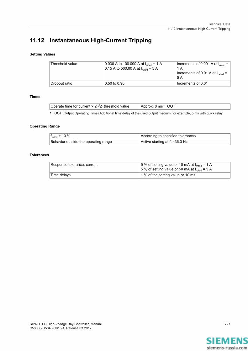
11.12 Instantaneous High-Current Tripping
Setting Values
Times
Operating Range
Tolerances
Threshold value 0.030 A to 100.000 A at Irated = 1 A0.15 A to 500.00 A at Irated = 5 A
Increments of 0.001 A at Irated = 1 AIncrements of 0.01 A at Irated = 5 A
Dropout ratio 0.50 to 0.90 Increments of 0.01
Operate time for current > 2·2· threshold value Approx. 8 ms + OOT1
1. OOT (Output Operating Time) Additional time delay of the used output medium, for example, 5 ms with quick relay
frated � 10 % According to specified tolerancesBehavior outside the operating range Active starting at f � 36.3 Hz
Response tolerance, current 5 % of setting value or 10 mA at Irated = 1 A5 % of setting value or 50 mA at Irated = 5 A
Time delays 1 % of the setting value or 10 ms

Technical Data11.13 Overvoltage Protection with 3-Phase Voltage
SIPROTEC High-Voltage Bay Controller, ManualC53000-G5040-C015-1, Release 03.2012
728
11.13 Overvoltage Protection with 3-Phase Voltage
Setting Values
Times
Operating Range
Tolerances
Measured value Phase-to-phasePhase-to-ground
Method of measurement Fundamental componentRMS value
Pickup value 0.300 V to 340.000 V Increments of 0.001 VTime delay 0.00 s to 60.00 s Increments of 0.01 sDropout ratio 0.90 to 0.99 Increments of 0.01
Operate time with time delay = 0 ms
Approx. 25 ms + OOT1 at 50 HzApprox. 22 ms + OOT at 60 Hz
1. OOT (Output Operating Time) additional delay of the output medium used, for example, 5 ms with fast relays, see Chapter 11.1.4 Relay Outputs
Dropout time Approx. 20 ms + OOT
10 Hz to 80 Hz According to specified tolerancesBehavior outside the operating range
Active
Voltages 0.5 % of setting value or 0.5 VTime delays 1 % of setting value or 10 ms

Technical Data11.14 Overvoltage Protection with Positive-Sequence Voltage
SIPROTEC High-Voltage Bay Controller, ManualC53000-G5040-C015-1, Release 03.2012
729
11.14 Overvoltage Protection with Positive-Sequence Voltage
Setting Values
Times
Operating Range
Tolerances
Pickup value 0.300 V to 200.000 V Increments of 0.001 VTime delay 0.00 s to 60.00 s Increments of 0.01 sDropout ratio 0.90 to 0.99 Increments of 0.01
Operate time with time delay = 0 ms Approx. 25 ms + OOT1 at 50 HzApprox. 22 ms + OOT at 60 Hz
1. OOT (Output Operating Time) additional delay of the output medium used, for example, 5 ms with fast relays, see Chapter 11.1.4 Relay Outputs
Dropout time Approx. 20 ms + OOT
10 Hz to 80 Hz According to specified tolerancesBehavior outside the operating range Active, but more insensitive
Voltages 0.5 % of the setting value or 0.5 VTime delays 1 % of the setting value or 10 ms

Technical Data11.15 Overvoltage Protection with Any Voltage
SIPROTEC High-Voltage Bay Controller, ManualC53000-G5040-C015-1, Release 03.2012
730
11.15 Overvoltage Protection with Any Voltage
Setting Values
Times
Operating Range
Tolerances
Measured value Measured voltage at transformer 1Measured voltage at transformer 2Measured voltage at transformer 3Measured voltage at transformer 4Calculated voltage VABCalculated voltage VBCCalculated voltage VCA
Method of measurement Fundamental componentRMS value
Pickup value 0.300 V to 340.000 V Increments of 0.001 VTime delay 0.00 s to 60.00 s Increments of 0.01 sDropout ratio 0.90 to 0.99 Increments of 0.01
Operate time with time delay = 0 ms Approx. 25 ms + OOT1 at 50 HzApprox. 22 ms + OOT at 60 Hz
1. OOT (Output Operating Time) additional delay of the output medium used, for example, 5 ms with fast relays, see Chapter 11.1.4 Relay Outputs
Dropout time Approx. 20 ms + OOT
10 Hz to 80 Hz According to specified tolerancesBehavior outside the operating range Active, but more insensitive
Voltages 0.5 % of the setting value or 0.5 VTime delays 1 % of the setting value or 10 ms
Technical Data11.16 Overfrequency Protection
SIPROTEC High-Voltage Bay Controller, ManualC53000-G5040-C015-1, Release 03.2012
731
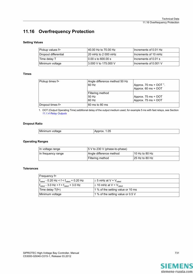
11.16 Overfrequency Protection
Setting Values
Times
Dropout Ratio
Operating Ranges
Tolerances
Pickup values f> 40.00 Hz to 70.00 Hz Increments of 0.01 HzDropout differential 20 mHz to 2 000 mHz Increments of 10 mHzTime delay T 0.00 s to 600.00 s Increments of 0.01 sMinimum voltage 3.000 V to 175.000 V Increments of 0.001 V
Pickup times f> Angle difference method 50 Hz60 Hz Approx. 70 ms + OOT 1.
Approx. 60 ms + OOT
1. OOT (Output Operating Time) additional delay of the output medium used, for example 5 ms with fast relays, see Section 11.1.4 Relay Outputs
Filtering method50 Hz60 Hz
Approx. 75 ms + OOTApprox. 75 ms + OOT
Dropout times f> 60 ms to 80 ms
Minimum voltage Approx. 1.05
In voltage range 5 V to 230 V (phase-to-phase)In frequency range Angle difference method 10 Hz to 80 Hz
Filtering method 25 Hz to 80 Hz
Frequency f>frated - 0.20 Hz < f < frated + 0.20 Hz � 5 mHz at V = Vrated
frated - 3.0 Hz < f < frated + 3.0 Hz � 10 mHz at V = Vrated
Time delay T(f>) 1 % of the setting value or 10 msMinimum voltage 1 % of the setting value or 0.5 V

Technical Data11.17 Underfrequency Protection
SIPROTEC High-Voltage Bay Controller, ManualC53000-G5040-C015-1, Release 03.2012
732
11.17 Underfrequency Protection
Setting Values
Times
Dropout Ratio
Operating Ranges
Tolerances
Pickup values f< 40.00 Hz to 70.00 Hz Increments of 0.01 HzDropout differential 20 mHz to 2 000 mHz Increments of 10 mHzTime delay T 0.00 s to 600.00 s Increments of 0.01 sMinimum voltage 3.000 V to 175.000 V Increments of 0.001 V
Pickup times f< Angle difference method 50 Hz60 Hz
80 ms/60 msApprox. 70 ms + OOT 1.Approx. 60 ms + OOT
1. OOT (Output Operating Time) additional delay of the output medium used, for example 5 ms with fast relays, see Section 11.1.4 Relay Outputs
Filtering method50 Hz60 Hz
95 ms/80 msApprox. 75 ms + OOTApprox. 75 ms + OOT
Dropout times f< 60 ms to 80 ms
Minimum voltage Approx. 1.05
In voltage range 5 V to 230 V (phase-to-phase)In frequency range Angle difference method 10 Hz to 80 Hz
Filtering method 25 Hz to 80 Hz
Frequency f<frated - 0.20 Hz < f < frated + 0.20 Hz � 5 mHz at V = Vrated
frated - 3.0 Hz < f < frated + 3.0 Hz � 10 mHz at V = Vrated
Time delay T (f<) 1 % of the setting value or 10 msMinimum voltage 1 % of the setting value or 0.5 V

Technical Data11.18 Instantaneous Tripping at Switch onto Fault
SIPROTEC High-Voltage Bay Controller, ManualC53000-G5040-C015-1, Release 03.2012
733
11.18 Instantaneous Tripping at Switch onto Fault
Setting Values
Tolerances
Tripping delay 0.00 s to 60.00 s Increments of 0.01 s
Times < 1 % of the setting value or 10 ms

Technical Data11.19 Circuit-Breaker Failure Protection
SIPROTEC High-Voltage Bay Controller, ManualC53000-G5040-C015-1, Release 03.2012
734
11.19 Circuit-Breaker Failure Protection
Starting Conditions
Setting Values
Dropout Ratios
Circuit-Breaker Supervision
NOTE
The circuit-breaker failure protection can also work without the circuit-breaker auxiliary contacts stated.
Auxiliary contacts are required for circuit-breaker failure protection in cases where the current flow is absent or too low for tripping (for example with a transformer or a Buchholz protection).
Times
Tolerances
For circuit-breaker failure protection 3-pole internal or external tripping 1
1. Via binary inputs
Phase-current threshold value
For Irated = 1 A 0.03 A to 100.00 A Increments of 0.01 AFor Irated = 5 A 0.15 A to 500.00 A
Ground-current threshold value
For Irated = 1 A 0.03 A to 100.00 A Increments of 0.01 AFor Irated = 5 A 0.15 A to 500.00 A
Supervision time of release signal 0.06 s to 1.00 s Increments of 0.01 sTime delays 0.05 s to 60.00 s Increments of 0.01 s
Current-threshold values Approx. 0.95
Position supervision of the circuit-breaker auxiliary contactsFor 3-pole CB tripping 1 input each for the make and break contact
Pickup time, in the case of an internal startPickup time, in the case of an external start
< 1 ms< 5 ms
Dropout time 1 via the current-flow criterion, for sinuso-idal quantities
1. The dropout time is the time required by the CBFP function to detect that the CB is open. The time for mechanically switching a contact is not included.
< 10 ms
Dropout time, via the flow current criterion, under all conditions
< 15 ms
Dropout time, via circuit-breaker auxiliary contact cri-terion
< 5 ms
Threshold values, dropout thresholds 2 % of setting value or 1 % of rated currentTimes 1 % of the setting value or 10 ms

Technical Data11.20 Negative-Sequence Protection with Definite Time Characteristic Curve
SIPROTEC High-Voltage Bay Controller, ManualC53000-G5040-C015-1, Release 03.2012
735
11.20 Negative-Sequence Protection with Definite Time Characteristic Curve
Setting Values
Times
Dropout Ratio
Operating Ranges
Tolerances
Reference value for I2 (Iref) Rated object current Irated, obj.Positive sequence current I1
Pickup value 5.0 % to 999.9 % l2/lref Increments of 0.1Time delay 0.00 s to 60.00 s Increments of 0.01 sRelease current (minimum current release) 0.03 A to 10.00 A at Irated = 1 A Increments of 0.01 AMaximum phase current (maximum current limit-ing)
0.03 A to 100.00 A at Irated = 5 A Increments of 0.01 A
Pickup times Approx. 35 msDropout times Approx. 35 ms
Stepped characteristic curve Approx. 0.95 for I2/Iref � 0.3
Current range 0.05 x Irated, obj � all phase currents � setting value Iph, max
Frequency range 10 Hz to 80 Hz
Pickup valueI2/Irated, obj Approx. 2 % of the setting value or 0.8 % absolute value (transformer mismatch-
ing < 4)I2/I1 Approx. 2 % of the setting value or 4 % absolute value (I1 > 50 mA (1 A) or 250
mA (5 A))Time delays 1 % of the setting value or 10 ms

Technical Data11.21 Thermal Overload Protection
SIPROTEC High-Voltage Bay Controller, ManualC53000-G5040-C015-1, Release 03.2012
736
11.21 Thermal Overload Protection
Setting Ranges/Increments
Dropout Ratios
Tolerances
Operate Curve
Current warning threshold 0.030 A to 100.000 A Increments of 0.001 AThermal warning threshold 50 % to 100 % Increments of 1 %Dropout threshold operate indication 50 % to 99 % Increments of 1 %Emergency startup seal-in time 0 s to 15 000 s Increments of 10 sK factor according to IEC 60225-8 0.10 to 4.00 Increments of 0.01Thermal time constant 30 s to 60 000 s Increments of 1 sCooling time constant 30 s to 60 000 s Increments of 1 sThermal lmax 0.030 A to 10.000 A Increments of 0.001 ACooling lmin 0.000 A to 10.000 A Increments of 0.001 A
Tripping threshold (fixed to 100 %) Dropout if operate indication dropout threshold falls shortThermal warning threshold Approx. 0.99 of the setting valueCurrent warning threshold Approx. 0.95 of the setting value
With reference to k* Irated For Irated = 1 A 2 % or 10 mA, class 2 % according to IEC 60255-8For Irated = 5 A 2 % or 50 mA, class 2 % according to IEC 60255-8
With reference to operate time 3 % or 1 s, class 3 % according to IEC 60255-8 for I/(k * Irated) > 1.25
Operate curve
[FoAuslos-211010-enUS-01.tif]
Where: t Operate time�th Time constantI Current load currentIpreload Preload currentk Setting factor according to VDE 0435 Part 3011 or
IEC 60255-8 (K factor)Irated, obj Rated current of the protected object

Technical Data11.21 Thermal Overload Protection
SIPROTEC High-Voltage Bay Controller, ManualC53000-G5040-C015-1, Release 03.2012
737
[DwAuslKe-100611-enUS-01.tif]
Figure 11-13 Operate Curve of the Overload Protection

Technical Data11.22 Inrush-Current Detection
SIPROTEC High-Voltage Bay Controller, ManualC53000-G5040-C015-1, Release 03.2012
738
11.22 Inrush-Current Detection
Setting Values
Times
Dropout Ratios
Operating Range
Tolerances
Operating-range limit lmax 0.030 A to 100.000 A at Irated = 1 A0.15 A to 500.00 A at Irated = 5 A
Increments of 0.001 AIncrements of 0.01 A
Content 2nd harmonic 10 % to 45 % Increments of 1 %Duration of the cross-blocking 0.03 s to 200.00 s Increments of 0.01 s
Pickup times Approx. 29 ms
Current measurement lmax 0.95 or 0.015 A at Irated = 1 A0.95 or 0.075 A at Irated = 5 A
Harmonic: I2nd Harm/I1st harm 0.95
10 Hz to 80 Hz According to specified tolerancesBehavior outside 10 Hz to 80 Hz Inactive
Current measurement lmax 1 % of the setting value or 5 mAHarmonic: I2nd Harm/I1st harm 1 % of the setting value for settings of l2nd Harm/1st Harm
Time delays 1 % of the setting value or 10 ms

Technical Data11.23 Synchronization Function
SIPROTEC High-Voltage Bay Controller, ManualC53000-G5040-C015-1, Release 03.2012
739
11.23 Synchronization Function
Operating Modes
Setting Values
Dropout Ratio
SynchrocheckSwitching synchronous networksSwitching asynchronous networksDe-energized switchingForced tripping
Supervision/Delay times:Max. duration of sync. process 0.00 s to 3 600.00 s or
(ineffective)Increments of 0.01 s
Superv. time de-energized switch-ing
0.00 s to 60.00 s Increments of 0.01 s
Activation delay 0.00 s to 60.00 s Increments of 0.01 sVoltage threshold values:Upper voltage limit Vmax 3.000 V to 340.000 V (phase-to-
phase)Increments of 0.001 V
Lower voltage limit Vmin 3.000 V to 170.000 V (phase-to-phase)
Increments of 0.001 V
V<, for off-circuit conditionsV>, for voltage present
3.000 V to 170.000 V (phase-to-phase)3.000 V to 340.000 V (phase-to-phase)
Increments of 0.001 VIncrements of 0.001 V
Differential values, changeover thresholds asynchronous/synchronous:Voltage differencesV2 > V1; V2 < V1
0.000 V to 170.000 V Increments of 0.001 V
Frequency difference f2 > f1; f2 < f1 0.00 Hz to 2.00 Hz Increments of 0.01 HzAngular difference �2 > �1; �2 < �1
0o to 90o Increments of 1o
�f threshold ASYN <-> SYN 0.01 Hz to 0.20 Hz Increments of 0.01 HzAdjustments of the sides:Angle adjustment 0o to 360o Increments of 1o
Voltage adjustment 0.500 to 2.000 Increments of 0.001Circuit breakerClosing time of the circuit breaker 0.01 s to 0.60 s Increments of 0.01 s
Voltages Approx. 0.9 (V>) or 1.1 (V<)Voltage difference 110 % or 0.5 VFrequency difference 105 % or 20 mHzAngular difference 1o

Technical Data11.23 Synchronization Function
SIPROTEC High-Voltage Bay Controller, ManualC53000-G5040-C015-1, Release 03.2012
740
Measured Values of the Synchronization Function
Times
Operating Range
Tolerances
Reference voltage V1• Range• Tolerance 1
1. at rated frequency
In kV primary, in V secondary or in % Vrated10 % to 120 % of Vrated� 1 % of the measured value or 0.5 % Vrated
Voltage to be synchronized V2• Range• Tolerance 1
In kV primary, in V secondary or in % Vrated10 % to 120 % of Vrated� 1 % of the measured value or 0.5 % Vrated
Frequency of the voltage V1f1• Range• Tolerance 1
f1 in Hz25 Hz � f � 70 Hz10 mHz
Frequency of the voltage V1f2• Range• Tolerance 1
f2 in Hz25 Hz � f � 70 Hz10 mHz
Voltage difference V2-V1• Range• Tolerance 1
In kV primary, in V secondary or in % Vrated10 % to 120 % of Vrated� 1 % of the measured value or 0.5 % Vrated
Frequency difference f2-f1• Range• Tolerance 1
In mHzfrated � 10 %5 mHz
Angular difference 2- 1• Range• Tolerance 1
In o-180o to +180o
0.5o
Measuring time, after switching on the variables Approx. 80 ms
Voltage 20 V to 340 VFrequency frated - 4 Hz � frated � frated + 4 Hz
Tolerances of the voltage settings 2 % of the excitation value or 1 VVoltage difference V2>V1; V2<V1 1 VFrequency difference f2>f1; f2<f1 10 mHzAngular difference �2>�1; �2<�1 1o
Tolerance of all time settings 1 % of the setting value or 10 msMax. phase displacement angle 5o for �f � 1 Hz
10o for �f > 1 Hz

Technical Data11.24 Broken-Wire Detection
SIPROTEC High-Voltage Bay Controller, ManualC53000-G5040-C015-1, Release 03.2012
741
11.24 Broken-Wire Detection
Setting Values
Value Setting Range IncrementMode of blocking Blocking
Automatic blockingNo blocking
-
Delta value for autoblock 0.004 I/Irated to 5.000 I/Irated 0.001

Technical Data11.25 Current-Balance Supervision
SIPROTEC High-Voltage Bay Controller, ManualC53000-G5040-C015-1, Release 03.2012
742
11.25 Current-Balance Supervision
Setting Values
Times
Release threshold value 0.030 A to 90.000 A at Irated = 1 A0.15 A to 450.00 A at Irated = 5 A
Increments of 0.001 AIncrements of 0.01 A
Threshold value min/max 0.10 to 0.95 Increments of 0.01Tripping delay 0.00 s to 100.00 s Increments of 0.01 s
Tripping time Approx. 500 msDropout time Approx. 500 ms

Technical Data11.26 Voltage-Balance Supervision
SIPROTEC High-Voltage Bay Controller, ManualC53000-G5040-C015-1, Release 03.2012
743
11.26 Voltage-Balance Supervision
Setting Values
Times
Release threshold value 0.300 V to 100.000 V Increments of 0.001 VThreshold value min/max 0.58 to 0.95 Increments of 0.01Tripping delay 0.00 s to 100.00 s Increments of 0.01 s
Tripping time Approx. 500 msDropout time Approx. 500 ms

Technical Data11.27 Current-Sum Supervision
SIPROTEC High-Voltage Bay Controller, ManualC53000-G5040-C015-1, Release 03.2012
744
11.27 Current-Sum Supervision
Setting Values
Times
Slope factor 0.00 to 0.95 Increments 0.01Threshold value 0.030 A to 10.000 A at Irated = 1 A
0.15 A to 50.00 A at Irated = 5 AIncrements of 0.001 AIncrements of 0.01 A
Tripping delay 0.00 s to 100.00 s Increments of 1.00 s
Tripping time Approx. 500 msDropout time Approx. 500 ms

Technical Data11.28 Voltage-Sum Supervision
SIPROTEC High-Voltage Bay Controller, ManualC53000-G5040-C015-1, Release 03.2012
745
11.28 Voltage-Sum Supervision
Setting Values
Times
Threshold value 0.300 V to 100.000 V Increments of 0.001 VTripping delay 0.00 s to 100.00 s Increments of 0.01 s
Tripping time Approx. 500 msDropout time Approx. 500 ms

Technical Data11.29 Current Phase-Rotation Supervision
SIPROTEC High-Voltage Bay Controller, ManualC53000-G5040-C015-1, Release 03.2012
746
11.29 Current Phase-Rotation Supervision
Setting Values
Times
Tripping delay 0.00 s to 100.00 s Increments of 0.01 sPhase-rotation direction A B C
A C B
Tripping time Approx. 500 msDropout time Approx. 500 ms
Technical Data11.30 Voltage Phase-Rotation Supervision
SIPROTEC High-Voltage Bay Controller, ManualC53000-G5040-C015-1, Release 03.2012
747
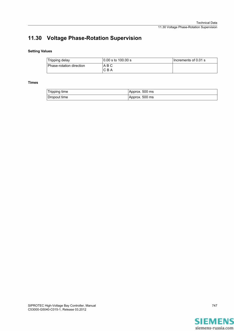
11.30 Voltage Phase-Rotation Supervision
Setting Values
Times
Tripping delay 0.00 s to 100.00 s Increments of 0.01 sPhase-rotation direction A B C
C B A
Tripping time Approx. 500 msDropout time Approx. 500 ms

Technical Data11.31 Trip-Circuit Supervision
SIPROTEC High-Voltage Bay Controller, ManualC53000-G5040-C015-1, Release 03.2012
748
11.31 Trip-Circuit Supervision
Setting Values
Number of monitored circuits per circuit-breaker function group 1 to 3Operating mode per circuit With 1 binary input
With 2 binary inputsPickup and dropout time Approx. 1 s to 2 sAdjustable indication delay with 1 binary input 1.00 s to 600.00 s Increments of 0.01 sAdjustable indication delay with 2 binary inputs 1.00 s to 30.00 s Increments of 0.01 s

Technical Data11.32 Supervision of Device-Internal Analog-Digital Converters
SIPROTEC High-Voltage Bay Controller, ManualC53000-G5040-C015-1, Release 03.2012
749
11.32 Supervision of Device-Internal Analog-Digital Converters
Setting Values
Times
Blockings
Slope factor 0.00 to 0.95 Increments of 0.01Threshold value 0.030 A to 10.000 A at Irated = 1.00 A
0.15 A to 50.00 A at Irated = 5.00 AIncrements of 0.001 AIncrements of 0.01 A
Tripping time Approx. 5 ms (faster than the fastest protection function)Dropout time Approx. 100 ms
Blocked protection functions Differential protection for lines, differential protection for transformers, motors, generators, busbars, ground-fault differential protection, overcur-rent protection (high-current stage)

Technical Data11.33 Operational Measured Values
SIPROTEC High-Voltage Bay Controller, ManualC53000-G5040-C015-1, Release 03.2012
750
11.33 Operational Measured Values
Voltages
Currents
Phase Angle
VA, VB, VC kV primary, V secondary, % of Vrated
Voltage rangeFrequency range
10 % to 200 % of Vrated47.5 Hz to 52.5 Hz at frated = 50 Hz57.5 Hz to 62.5 Hz at frated = 60 Hz
Tolerance 0.2 % of the measured value in the above rangesVAB, VBC, VCA kV primary, V secondary, % of Vrated
Voltage rangeFrequency range
10 % to 200 % of Vrated47.5 Hz to 52.5 Hz at frated = 50 Hz57.5 Hz to 62.5 Hz at frated = 60 Hz
Tolerance 0.2 % of the measured value in the above ranges
IA, IB, IC, 3I0 A secondaryCurrent rangeRated rangeMeasuring rangesFrequency range
Measurement from 0.1 A to 25 A1 A, 5 A100 · Ir, 1.6 · Ir47.5 Hz to 52.5 Hz at frated = 50 Hz57.5 Hz to 62.5 Hz at frated = 60 Hz
Tolerance 0.2 % of the measured value in the above ranges
�V °Frequency range 47.5 Hz to 52.5 Hz at frated = 50 Hz
57.5 Hz to 62.5 Hz at frated = 60 HzTolerance �V 0.2 ° at rated voltage�I °Frequency range 47.5 Hz to 52.5 Hz at frated = 50 Hz
57.5 Hz to 62.5 Hz at frated = 60 HzTolerance �I 0.2 ° at rated current

Technical Data11.33 Operational Measured Values
SIPROTEC High-Voltage Bay Controller, ManualC53000-G5040-C015-1, Release 03.2012
751
Ratings
Frequency
Active power P MWRange P
Rated-current rangeCurrent measuring rangesFrequency range
50 % to 120 % and ABS (cos �) � 0.071 A, 5 A100 · Ir, 1.6 · Ir47.5 Hz to 52.5 Hz at frated = 50 Hz57.5 Hz to 62.5 Hz at frated = 60 Hz
Tolerance P 0.5 % Prated with I/Irated and V/Vrated PA, PB, PC -Apparent power S MVARange S 50 % to 120 % Tolerance S 0.5 % Srated with I/Irated and V/Vrated SA, SB, SC -Reactive power Q MVArRange Q 50 % to 120 % and
ABS (cos �) � 0.07Tolerance Q 1 % Prated with I/Irated and V/Vrated Power factor °Tolerance 0.02QA, QB, QC -
Frequency f Hz and % frated
Range 10 Hz to 80 HzTolerance 20 mHz in the range frated � 10 % for rated variables

Technical Data11.34 Energy Values
SIPROTEC High-Voltage Bay Controller, ManualC53000-G5040-C015-1, Release 03.2012
752
11.34 Energy Values
Setting Values
■
Active energy WpReactive energy Wq
kWh, MWh, GWh kvarh, Mvarh, Gvarh
Range � 2 % for I > 0.1 Irated, V > 0.1 Vrated |cos�| � 0.707
Tolerance at rated frequency 1 %