Embed Size (px)
Citation preview
SIP Binding
The SIP Binding feature enables you to configure a source IP address for signaling packets andmedia packets.
• Feature Information for SIP Binding, page 1
• Information About SIP Binding, page 2
• Configuring SIP Binding, page 10
• Verifying SIP Binding, page 12
Feature Information for SIP BindingThe following table provides release information about the feature or features described in this module. Thistable lists only the software release that introduced support for a given feature in a given software releasetrain. Unless noted otherwise, subsequent releases of that software release train also support that feature.
Use Cisco Feature Navigator to find information about platform support and Cisco software image support.To access Cisco Feature Navigator, go to www.cisco.com/go/cfn. An account on Cisco.com is not required.
Cisco Unified Border Element Configuration Guide 1
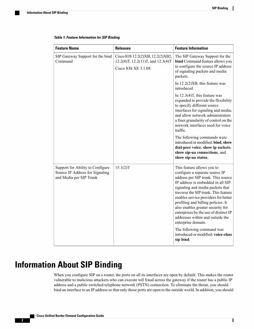
Table 1: Feature Information for SIP Binding
Feature InformationReleasesFeature Name
The SIP Gateway Support for thebindCommand feature allows youto configure the source IP addressof signaling packets and mediapackets.
In 12.2(2)XB, this feature wasintroduced.
In 12.3(4)T, this feature wasexpanded to provide the flexibilityto specify different sourceinterfaces for signaling and media,and allow network administratorsa finer granularity of control on thenetwork interfaces used for voicetraffic.
The following commands wereintroduced ormodified: bind, showdial-peer voice, show ip sockets,show sip-ua connections, andshow sip-ua status.
Cisco IOS 12.2(2)XB, 12.2(2)XB2,12.2(8)T, 12.2(11)T, and 12.3(4)T
Cisco IOS XE 3.1.0S
SIP Gateway Support for the bindCommand
This feature allows you toconfigure a separate source IPaddress per SIP trunk. This sourceIP address is embedded in all SIPsignaling and media packets thattraverse the SIP trunk. This featureenables service providers for betterprofiling and billing policies. Italso enables greater security forenterprises by the use of distinct IPaddresses within and outside theenterprise domain.
The following command wasintroduced ormodified: voice-classsip bind.
15.1(2)TSupport for Ability to ConfigureSource IP Address for Signalingand Media per SIP Trunk
Information About SIP BindingWhen you configure SIP on a router, the ports on all its interfaces are open by default. This makes the routervulnerable to malicious attackers who can execute toll fraud across the gateway if the router has a public IPaddress and a public switched telephone network (PSTN) connection. To eliminate the threat, you shouldbind an interface to an IP address so that only those ports are open to the outside world. In addition, you should
Cisco Unified Border Element Configuration Guide2
SIP BindingInformation About SIP Binding
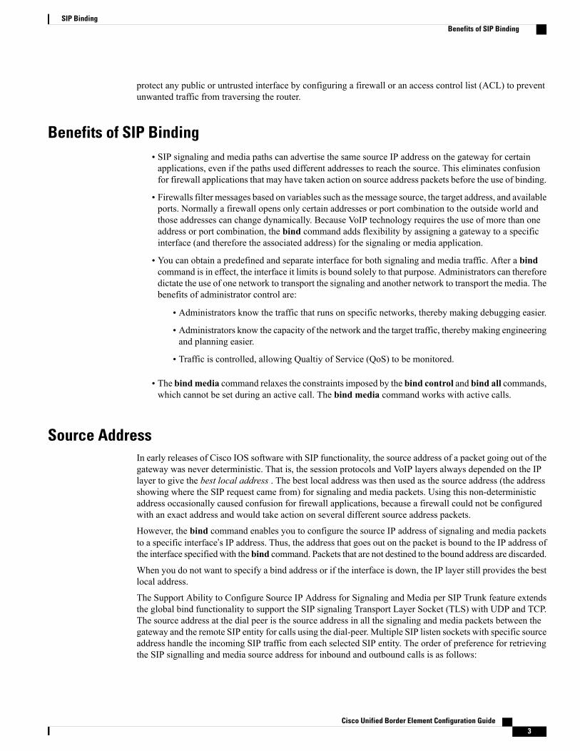
protect any public or untrusted interface by configuring a firewall or an access control list (ACL) to preventunwanted traffic from traversing the router.
Benefits of SIP Binding• SIP signaling and media paths can advertise the same source IP address on the gateway for certainapplications, even if the paths used different addresses to reach the source. This eliminates confusionfor firewall applications that may have taken action on source address packets before the use of binding.
• Firewalls filter messages based on variables such as the message source, the target address, and availableports. Normally a firewall opens only certain addresses or port combination to the outside world andthose addresses can change dynamically. Because VoIP technology requires the use of more than oneaddress or port combination, the bind command adds flexibility by assigning a gateway to a specificinterface (and therefore the associated address) for the signaling or media application.
• You can obtain a predefined and separate interface for both signaling and media traffic. After a bindcommand is in effect, the interface it limits is bound solely to that purpose. Administrators can thereforedictate the use of one network to transport the signaling and another network to transport the media. Thebenefits of administrator control are:
• Administrators know the traffic that runs on specific networks, thereby making debugging easier.
• Administrators know the capacity of the network and the target traffic, thereby making engineeringand planning easier.
• Traffic is controlled, allowing Qualtiy of Service (QoS) to be monitored.
• The bindmedia command relaxes the constraints imposed by the bind control and bind all commands,which cannot be set during an active call. The bind media command works with active calls.
Source AddressIn early releases of Cisco IOS software with SIP functionality, the source address of a packet going out of thegateway was never deterministic. That is, the session protocols and VoIP layers always depended on the IPlayer to give the best local address . The best local address was then used as the source address (the addressshowing where the SIP request came from) for signaling and media packets. Using this non-deterministicaddress occasionally caused confusion for firewall applications, because a firewall could not be configuredwith an exact address and would take action on several different source address packets.
However, the bind command enables you to configure the source IP address of signaling and media packetsto a specific interface’s IP address. Thus, the address that goes out on the packet is bound to the IP address ofthe interface specified with the bind command. Packets that are not destined to the bound address are discarded.
When you do not want to specify a bind address or if the interface is down, the IP layer still provides the bestlocal address.
The Support Ability to Configure Source IP Address for Signaling and Media per SIP Trunk feature extendsthe global bind functionality to support the SIP signaling Transport Layer Socket (TLS) with UDP and TCP.The source address at the dial peer is the source address in all the signaling and media packets between thegateway and the remote SIP entity for calls using the dial-peer. Multiple SIP listen sockets with specific sourceaddress handle the incoming SIP traffic from each selected SIP entity. The order of preference for retrievingthe SIP signalling and media source address for inbound and outbound calls is as follows:
Cisco Unified Border Element Configuration Guide 3
SIP BindingBenefits of SIP Binding
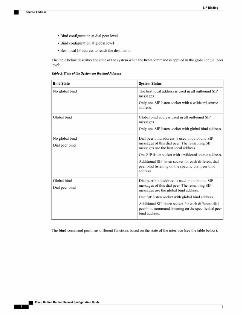
• Bind configuration at dial peer level
• Bind configuration at global level
• Best local IP address to reach the destination
The table below describes the state of the system when the bind command is applied in the global or dial peerlevel:
Table 2: State of the System for the bind Address
System StatusBind State
The best local address is used in all outbound SIPmessages.
Only one SIP listen socket with a wildcard sourceaddress.
No global bind
Global bind address used in all outbound SIPmessages.
Only one SIP listen socket with global bind address.
Global bind
Dial peer bind address is used in outbound SIPmessages of this dial peer. The remaining SIPmessages use the best local address.
One SIP listen socket with a wildcard source address.
Additional SIP listen socket for each different dialpeer bind listening on the specific dial peer bindaddress.
No global bind
Dial peer bind
Dial peer bind address is used in outbound SIPmessages of this dial peer. The remaining SIPmessages use the global bind address.
One SIP listen socket with global bind address.
Additional SIP listen socket for each different dialpeer bind command listening on the specific dial peerbind address.
Global bind
Dial peer bind
The bind command performs different functions based on the state of the interface (see the table below).
Cisco Unified Border Element Configuration Guide4
SIP BindingSource Address
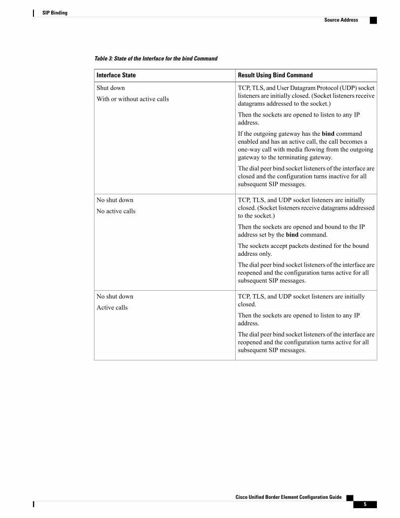
Table 3: State of the Interface for the bind Command
Result Using Bind CommandInterface State
TCP, TLS, andUser Datagram Protocol (UDP) socketlisteners are initially closed. (Socket listeners receivedatagrams addressed to the socket.)
Then the sockets are opened to listen to any IPaddress.
If the outgoing gateway has the bind commandenabled and has an active call, the call becomes aone-way call with media flowing from the outgoinggateway to the terminating gateway.
The dial peer bind socket listeners of the interface areclosed and the configuration turns inactive for allsubsequent SIP messages.
Shut down
With or without active calls
TCP, TLS, and UDP socket listeners are initiallyclosed. (Socket listeners receive datagrams addressedto the socket.)
Then the sockets are opened and bound to the IPaddress set by the bind command.
The sockets accept packets destined for the boundaddress only.
The dial peer bind socket listeners of the interface arereopened and the configuration turns active for allsubsequent SIP messages.
No shut down
No active calls
TCP, TLS, and UDP socket listeners are initiallyclosed.
Then the sockets are opened to listen to any IPaddress.
The dial peer bind socket listeners of the interface arereopened and the configuration turns active for allsubsequent SIP messages.
No shut down
Active calls
Cisco Unified Border Element Configuration Guide 5
SIP BindingSource Address
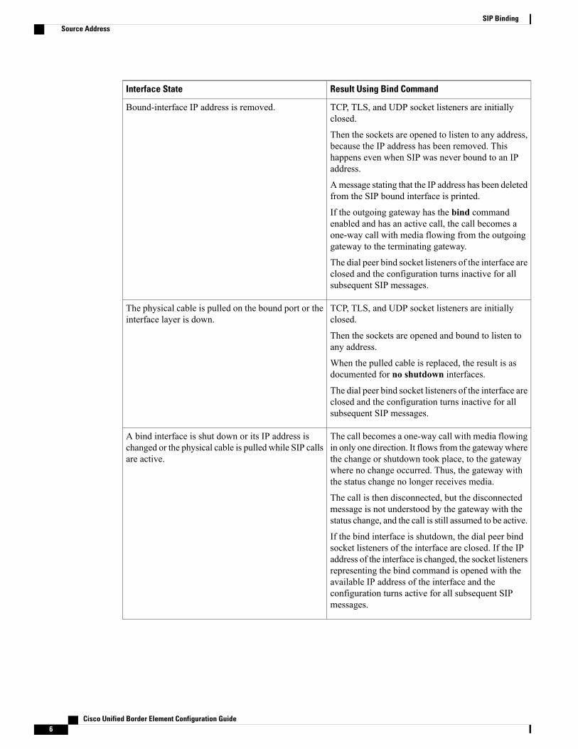
Result Using Bind CommandInterface State
TCP, TLS, and UDP socket listeners are initiallyclosed.
Then the sockets are opened to listen to any address,because the IP address has been removed. Thishappens even when SIP was never bound to an IPaddress.
Amessage stating that the IP address has been deletedfrom the SIP bound interface is printed.
If the outgoing gateway has the bind commandenabled and has an active call, the call becomes aone-way call with media flowing from the outgoinggateway to the terminating gateway.
The dial peer bind socket listeners of the interface areclosed and the configuration turns inactive for allsubsequent SIP messages.
Bound-interface IP address is removed.
TCP, TLS, and UDP socket listeners are initiallyclosed.
Then the sockets are opened and bound to listen toany address.
When the pulled cable is replaced, the result is asdocumented for no shutdown interfaces.
The dial peer bind socket listeners of the interface areclosed and the configuration turns inactive for allsubsequent SIP messages.
The physical cable is pulled on the bound port or theinterface layer is down.
The call becomes a one-way call with media flowingin only one direction. It flows from the gatewaywherethe change or shutdown took place, to the gatewaywhere no change occurred. Thus, the gateway withthe status change no longer receives media.
The call is then disconnected, but the disconnectedmessage is not understood by the gateway with thestatus change, and the call is still assumed to be active.
If the bind interface is shutdown, the dial peer bindsocket listeners of the interface are closed. If the IPaddress of the interface is changed, the socket listenersrepresenting the bind command is opened with theavailable IP address of the interface and theconfiguration turns active for all subsequent SIPmessages.
A bind interface is shut down or its IP address ischanged or the physical cable is pulled while SIP callsare active.
Cisco Unified Border Element Configuration Guide6
SIP BindingSource Address
Result Using Bind CommandInterface State
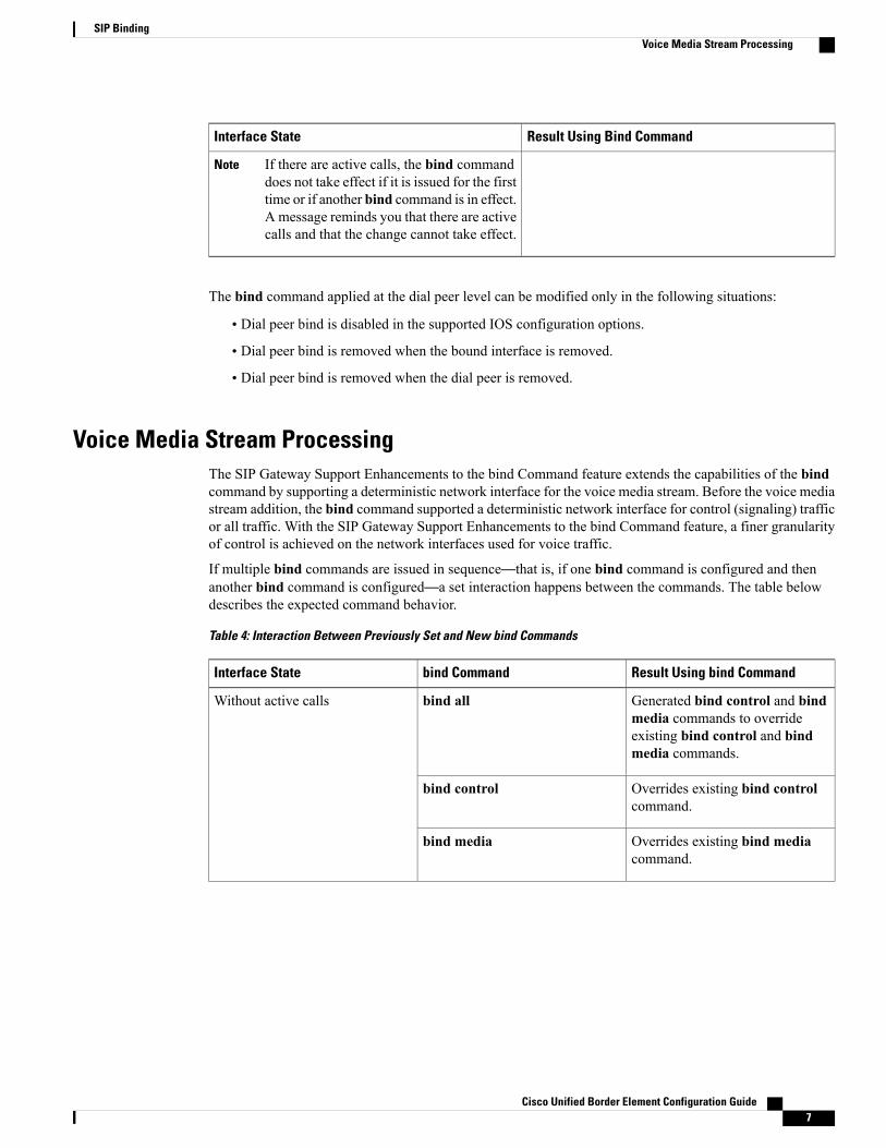
If there are active calls, the bind commanddoes not take effect if it is issued for the firsttime or if another bind command is in effect.A message reminds you that there are activecalls and that the change cannot take effect.
Note
The bind command applied at the dial peer level can be modified only in the following situations:
• Dial peer bind is disabled in the supported IOS configuration options.
• Dial peer bind is removed when the bound interface is removed.
• Dial peer bind is removed when the dial peer is removed.
Voice Media Stream ProcessingThe SIP Gateway Support Enhancements to the bind Command feature extends the capabilities of the bindcommand by supporting a deterministic network interface for the voice media stream. Before the voice mediastream addition, the bind command supported a deterministic network interface for control (signaling) trafficor all traffic. With the SIP Gateway Support Enhancements to the bind Command feature, a finer granularityof control is achieved on the network interfaces used for voice traffic.
If multiple bind commands are issued in sequence—that is, if one bind command is configured and thenanother bind command is configured—a set interaction happens between the commands. The table belowdescribes the expected command behavior.
Table 4: Interaction Between Previously Set and New bind Commands
Result Using bind Commandbind CommandInterface State
Generated bind control and bindmedia commands to overrideexisting bind control and bindmedia commands.
bind allWithout active calls
Overrides existing bind controlcommand.
bind control
Overrides existing bind mediacommand.
bind media
Cisco Unified Border Element Configuration Guide 7
SIP BindingVoice Media Stream Processing
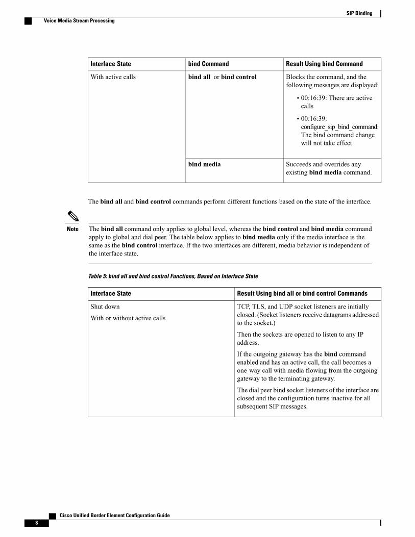
Result Using bind Commandbind CommandInterface State
Blocks the command, and thefollowing messages are displayed:
• 00:16:39: There are activecalls
• 00:16:39:configure_sip_bind_command:The bind command changewill not take effect
bind all or bind controlWith active calls
Succeeds and overrides anyexisting bind media command.
bind media
The bind all and bind control commands perform different functions based on the state of the interface.
The bind all command only applies to global level, whereas the bind control and bind media commandapply to global and dial peer. The table below applies to bind media only if the media interface is thesame as the bind control interface. If the two interfaces are different, media behavior is independent ofthe interface state.
Note
Table 5: bind all and bind control Functions, Based on Interface State
Result Using bind all or bind control CommandsInterface State
TCP, TLS, and UDP socket listeners are initiallyclosed. (Socket listeners receive datagrams addressedto the socket.)
Then the sockets are opened to listen to any IPaddress.
If the outgoing gateway has the bind commandenabled and has an active call, the call becomes aone-way call with media flowing from the outgoinggateway to the terminating gateway.
The dial peer bind socket listeners of the interface areclosed and the configuration turns inactive for allsubsequent SIP messages.
Shut down
With or without active calls
Cisco Unified Border Element Configuration Guide8
SIP BindingVoice Media Stream Processing

Result Using bind all or bind control CommandsInterface State
TCP, TLS, and UDP socket listeners are initiallyclosed. (Socket listeners receive datagrams addressedto the socket.)
Then the sockets are opened and bound to the IPaddress set by the bind command.
The sockets accept packets destined for the boundaddress only.
The dial peer bind socket listeners of the interface arereopened and the configuration turns active for allsubsequent SIP messages.
Not shut down
Without active calls
TCP, TLS, and UDP socket listeners are initiallyclosed.
Then the sockets are opened to listen to any IPaddress.
The dial peer bind socket listeners of the interface arereopened and the configuration turns active for allsubsequent SIP messages.
Not shut down
With active calls
TCP, TLS, and UDP socket listeners are initiallyclosed.
Then the sockets are opened to listen to any addressbecause the IP address has been removed.
A message is printed that states the IP address hasbeen deleted from the bound SIP interface.
If the outgoing gateway has the bind commandenabled and has an active call, the call becomes aone-way call with media flowing from the outgoinggateway to the terminating gateway.
The dial peer bind socket listeners of the interface areclosed and the configuration turns inactive for allsubsequent SIP messages.
Bound interface’s IP address is removed.
TCP, TLS, and UDP socket listeners are initiallyclosed.
Then the sockets are opened and bound to listen toany address.
When the pulled cable is replaced, the result is asdocumented for interfaces that are not shut down.
The dial peer bind socket listeners of the interface areclosed and the configuration turns inactive for allsubsequent SIP messages.
The physical cable is pulled on the bound port, or theinterface layer goes down.
Cisco Unified Border Element Configuration Guide 9
SIP BindingVoice Media Stream Processing

Result Using bind all or bind control CommandsInterface State
The call becomes a one-way call with media flowingin only one direction. The media flows from thegateway where the change or shutdown took place tothe gateway where no change occurred. Thus, thegateway with the status change no longer receivesmedia.
The call is then disconnected, but the disconnectedmessage is not understood by the gateway with thestatus change, and the call is still assumed to be active.
If the bind interface is shutdown, the dial peer bindsocket listeners of the interface are closed. If the IPaddress of the interface is changed, the socket listenersrepresenting the bind command is opened with theavailable IP address of the interface and theconfiguration turns active for all subsequent SIPmessages.
A bind interface is shut down, or its IP address ischanged, or the physical cable is pulled while SIPcalls are active.
Configuring SIP BindingSUMMARY STEPS
1. enable2. configure terminal3. interface type number4. ip address ip-addressmask [secondary]5. exit6. Use one of the following commands to configure SIP binding:
• bind {control | all} source-interface interface-id [ipv6-address ipv6-address] in SIP configurationmode.
• bind media {source-address ipv4 ipv4-address | source-interface interface-id [ipv6-addressipv6-address]} in SIP configuration mode.
• voice-class sip bind control source interface interface-id [ipv6-address ipv6-address] in dial-peerconfiguration mode.
• voice-class sip bind media {source-address ipv4 ipv4-address | source-interface interface-id[ipv6-address ipv6-address]} in dial-peer configuration mode.
7. end
Cisco Unified Border Element Configuration Guide10
SIP BindingConfiguring SIP Binding
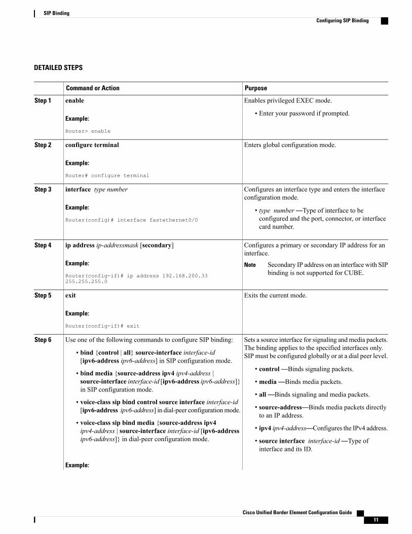
DETAILED STEPS
PurposeCommand or Action
Enables privileged EXEC mode.enableStep 1
Example:
Router> enable
• Enter your password if prompted.
Enters global configuration mode.configure terminal
Example:
Router# configure terminal
Step 2
Configures an interface type and enters the interfaceconfiguration mode.
interface type number
Example:
Router(config)# interface fastethernet0/0
Step 3
• type number —Type of interface to beconfigured and the port, connector, or interfacecard number.
Configures a primary or secondary IP address for aninterface.
ip address ip-addressmask [secondary]
Example:
Router(config-if)# ip address 192.168.200.33255.255.255.0
Step 4
Secondary IP address on an interface with SIPbinding is not supported for CUBE.
Note
Exits the current mode.exit
Example:
Router(config-if)# exit
Step 5
Sets a source interface for signaling andmedia packets.The binding applies to the specified interfaces only.SIP must be configured globally or at a dial peer level.
Use one of the following commands to configure SIP binding:Step 6
• bind {control | all} source-interface interface-id[ipv6-address ipv6-address] in SIP configuration mode.
• control—Binds signaling packets.• bind media {source-address ipv4 ipv4-address |source-interface interface-id [ipv6-address ipv6-address]}in SIP configuration mode.
• media—Binds media packets.
• all—Binds signaling and media packets.• voice-class sip bind control source interface interface-id[ipv6-address ipv6-address] in dial-peer configurationmode. • source-address—Binds media packets directly
to an IP address.• voice-class sip bind media {source-address ipv4ipv4-address | source-interface interface-id [ipv6-addressipv6-address]} in dial-peer configuration mode.
• ipv4 ipv4-address—Configures the IPv4 address.
• source interface interface-id—Type ofinterface and its ID.
Example:
Cisco Unified Border Element Configuration Guide 11
SIP BindingConfiguring SIP Binding
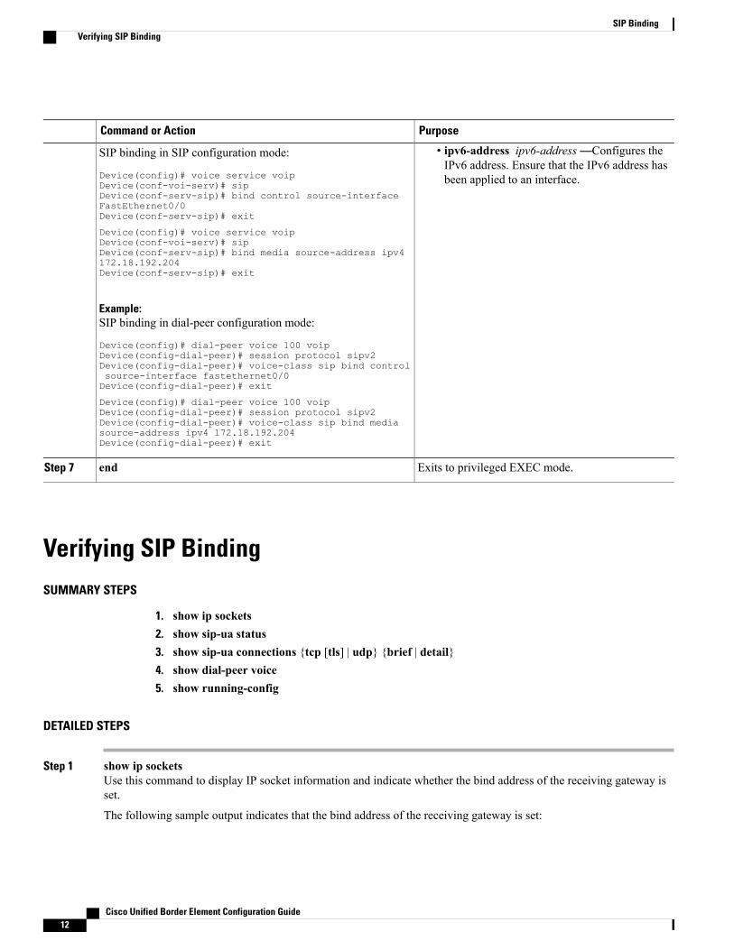
PurposeCommand or Action
• ipv6-address ipv6-address —Configures theIPv6 address. Ensure that the IPv6 address hasbeen applied to an interface.
SIP binding in SIP configuration mode:
Device(config)# voice service voipDevice(conf-voi-serv)# sipDevice(conf-serv-sip)# bind control source-interfaceFastEthernet0/0Device(conf-serv-sip)# exit
Device(config)# voice service voipDevice(conf-voi-serv)# sipDevice(conf-serv-sip)# bind media source-address ipv4172.18.192.204Device(conf-serv-sip)# exit
Example:SIP binding in dial-peer configuration mode:
Device(config)# dial-peer voice 100 voipDevice(config-dial-peer)# session protocol sipv2Device(config-dial-peer)# voice-class sip bind controlsource-interface fastethernet0/0Device(config-dial-peer)# exit
Device(config)# dial-peer voice 100 voipDevice(config-dial-peer)# session protocol sipv2Device(config-dial-peer)# voice-class sip bind mediasource-address ipv4 172.18.192.204Device(config-dial-peer)# exit
Exits to privileged EXEC mode.endStep 7
Verifying SIP BindingSUMMARY STEPS
1. show ip sockets2. show sip-ua status3. show sip-ua connections {tcp [tls] | udp} {brief | detail}4. show dial-peer voice5. show running-config
DETAILED STEPS
Step 1 show ip socketsUse this command to display IP socket information and indicate whether the bind address of the receiving gateway isset.
The following sample output indicates that the bind address of the receiving gateway is set:
Cisco Unified Border Element Configuration Guide12
SIP BindingVerifying SIP Binding
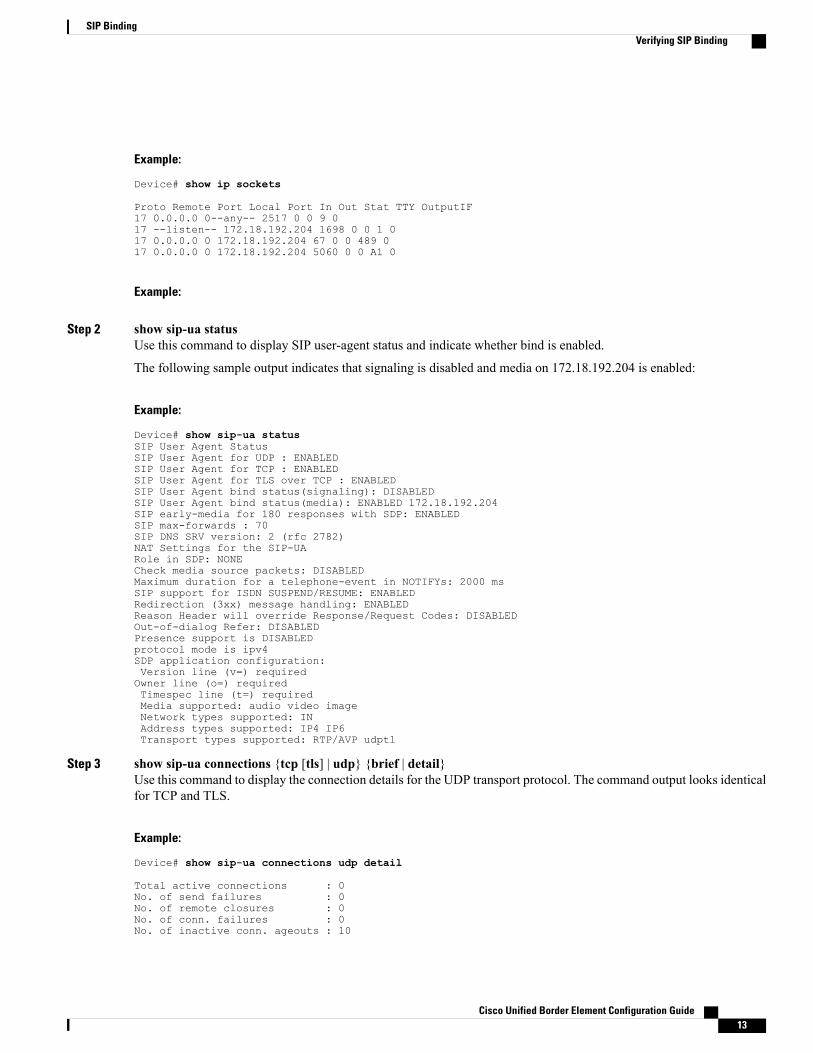
Example:
Device# show ip sockets
Proto Remote Port Local Port In Out Stat TTY OutputIF17 0.0.0.0 0--any-- 2517 0 0 9 017 --listen-- 172.18.192.204 1698 0 0 1 017 0.0.0.0 0 172.18.192.204 67 0 0 489 017 0.0.0.0 0 172.18.192.204 5060 0 0 A1 0
Example:
Step 2 show sip-ua statusUse this command to display SIP user-agent status and indicate whether bind is enabled.
The following sample output indicates that signaling is disabled and media on 172.18.192.204 is enabled:
Example:
Device# show sip-ua statusSIP User Agent StatusSIP User Agent for UDP : ENABLEDSIP User Agent for TCP : ENABLEDSIP User Agent for TLS over TCP : ENABLEDSIP User Agent bind status(signaling): DISABLEDSIP User Agent bind status(media): ENABLED 172.18.192.204SIP early-media for 180 responses with SDP: ENABLEDSIP max-forwards : 70SIP DNS SRV version: 2 (rfc 2782)NAT Settings for the SIP-UARole in SDP: NONECheck media source packets: DISABLEDMaximum duration for a telephone-event in NOTIFYs: 2000 msSIP support for ISDN SUSPEND/RESUME: ENABLEDRedirection (3xx) message handling: ENABLEDReason Header will override Response/Request Codes: DISABLEDOut-of-dialog Refer: DISABLEDPresence support is DISABLEDprotocol mode is ipv4SDP application configuration:Version line (v=) requiredOwner line (o=) requiredTimespec line (t=) requiredMedia supported: audio video imageNetwork types supported: INAddress types supported: IP4 IP6Transport types supported: RTP/AVP udptl
Step 3 show sip-ua connections {tcp [tls] | udp} {brief | detail}Use this command to display the connection details for the UDP transport protocol. The command output looks identicalfor TCP and TLS.
Example:
Device# show sip-ua connections udp detail
Total active connections : 0No. of send failures : 0No. of remote closures : 0No. of conn. failures : 0No. of inactive conn. ageouts : 10
Cisco Unified Border Element Configuration Guide 13
SIP BindingVerifying SIP Binding

---------Printing Detailed Connection Report---------Note:** Tuples with no matching socket entry
- Do 'clear sip <tcp[tls]/udp> conn t ipv4:<addr>:<port>'to overcome this error condition
++ Tuples with mismatched address/port entry- Do 'clear sip <tcp[tls]/udp> conn t ipv4:<addr>:<port> id <connid>'to overcome this error condition
No Active Connections Found-------------- SIP Transport Layer Listen Sockets ---------------Conn-Id Local-Address=========== =============================2 [9.42.28.29]:5060
Step 4 show dial-peer voiceUse this command, for each dial peer configured, to verify that the dial-peer configuration is correct. The following issample output from this command for a VoIP dial peer:
Example:
Device# show dial-peer voice 101
VoiceOverIpPeer1234peer type = voice, system default peer = FALSE, information type = voice,description = `',tag = 1234, destination-pattern = `',voice reg type = 0, corresponding tag = 0,allow watch = FALSEanswer-address = `', preference=0,CLID Restriction = NoneCLID Network Number = `'CLID Second Number sentCLID Override RDNIS = disabled,rtp-ssrc mux = systemsource carrier-id = `', target carrier-id = `',source trunk-group-label = `', target trunk-group-label = `',numbering Type = `unknown'group = 1234, Admin state is up, Operation state is down,incoming called-number = `', connections/maximum = 0/unlimited,DTMF Relay = disabled,modem transport = system,URI classes:
Incoming (Request) =Incoming (Via) =Incoming (To) =Incoming (From) =Destination =
huntstop = disabled,in bound application associated: 'DEFAULT'out bound application associated: ''dnis-map =permission :bothincoming COR list:maximum capabilityoutgoing COR list:minimum requirementoutgoing LPCOR:Translation profile (Incoming):Translation profile (Outgoing):incoming call blocking:translation-profile = `'disconnect-cause = `no-service'advertise 0x40 capacity_update_timer 25 addrFamily 4 oldAddrFamily 4mailbox selection policy: nonetype = voip, session-target = `',technology prefix:settle-call = disabledip media DSCP = ef, ip media rsvp-pass DSCP = efip media rsvp-fail DSCP = ef, ip signaling DSCP = af31,ip video rsvp-none DSCP = af41,ip video rsvp-pass DSCP = af41
Cisco Unified Border Element Configuration Guide14
SIP BindingVerifying SIP Binding

ip video rsvp-fail DSCP = af41,ip defending Priority = 0, ip preemption priority = 0ip policy locator voice:ip policy locator video:UDP checksum = disabled,session-protocol = sipv2, session-transport = system,req-qos = best-effort, acc-qos = best-effort,req-qos video = best-effort, acc-qos video = best-effort,req-qos audio def bandwidth = 64, req-qos audio max bandwidth = 0,req-qos video def bandwidth = 384, req-qos video max bandwidth = 0,RTP dynamic payload type values: NTE = 101Cisco: NSE=100, fax=96, fax-ack=97, dtmf=121, fax-relay=122
CAS=123, TTY=119, ClearChan=125, PCM switch over u-law=0,A-law=8, GSMAMR-NB=117 iLBC=116, AAC-ld=114, iSAC=124lmr_tone=0, nte_tone=0h263+=118, h264=119G726r16 using static payloadG726r24 using static payload
RTP comfort noise payload type = 19fax rate = voice, payload size = 20 bytesfax protocol = systemfax-relay ecm enableFax Relay ans enabledFax Relay SG3-to-G3 Enabled (by system configuration)fax NSF = 0xAD0051 (default)codec = g729r8, payload size = 20 bytes,video codec = Nonevoice class codec = `'voice class sip session refresh systemvoice class sip rsvp-fail-policy voice post-alert mandatory keep-alive interval 30voice class sip rsvp-fail-policy voice post-alert optional keep-alive interval 30voice class sip rsvp-fail-policy video post-alert mandatory keep-alive interval 30voice class sip rsvp-fail-policy video post-alert optional keep-alive interval 30text relay = disabledMedia Setting = forking (disabled) flow-through (global)Expect factor = 10, Icpif = 20,Playout Mode is set to adaptive,Initial 60 ms, Max 1000 msPlayout-delay Minimum mode is set to default, value 40 msFax nominal 300 msMax Redirects = 1, signaling-type = cas,VAD = enabled, Poor QOV Trap = disabled,Source Interface = NONEvoice class sip url = system,voice class sip tel-config url = system,voice class sip rel1xx = system,voice class sip anat = system,voice class sip outbound-proxy = "system",voice class sip associate registered-number =
system,voice class sip asserted-id system,voice class sip privacy systemvoice class sip e911 = system,voice class sip history-info = system,voice class sip reset timer expires 183 = system,voice class sip pass-thru headers = system,voice class sip pass-thru content unsupp = system,voice class sip pass-thru content sdp = system,voice class sip copy-list = system,voice class sip g729 annexb-all = system,voice class sip early-offer forced = system,voice class sip negotiate cisco = system,voice class sip block 180 = system,voice class sip block 183 = system,voice class sip block 181 = system,voice class sip preloaded-route = system,voice class sip random-contact = system,voice class sip random-request-uri validate = system,voice class sip call-route p-called-party-id = system,voice class sip call-route history-info = system,voice class sip privacy-policy send-always = system,
Cisco Unified Border Element Configuration Guide 15
SIP BindingVerifying SIP Binding
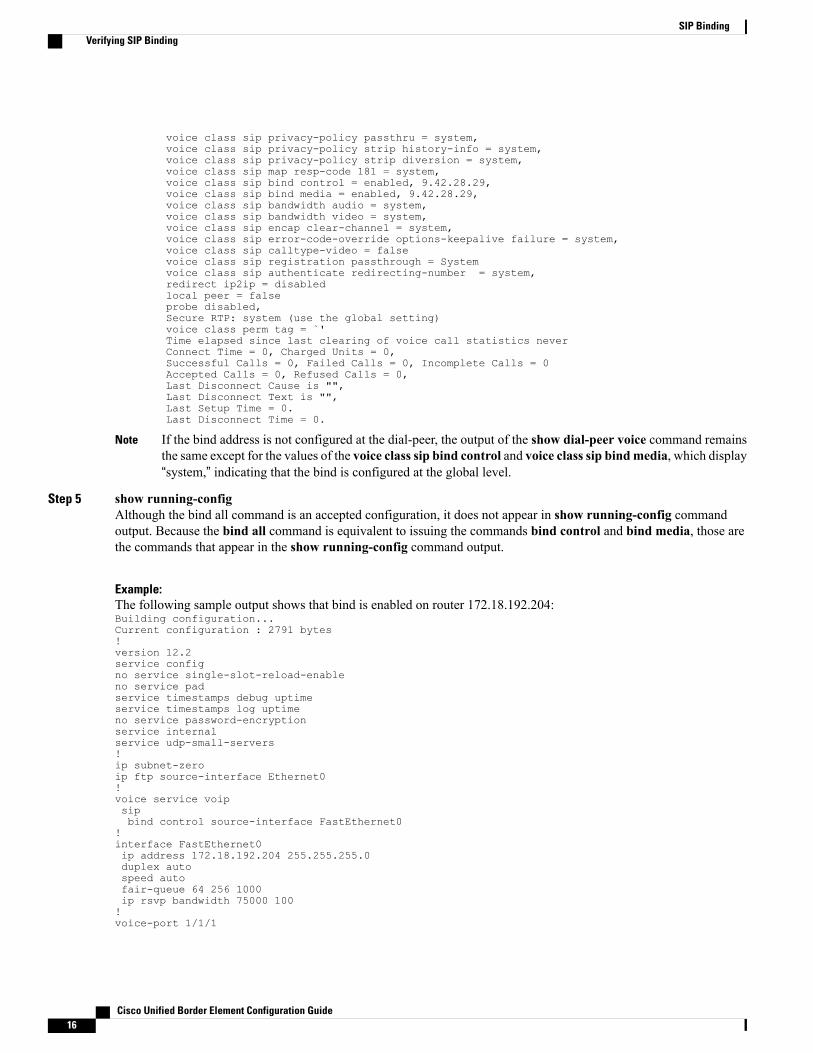
voice class sip privacy-policy passthru = system,voice class sip privacy-policy strip history-info = system,voice class sip privacy-policy strip diversion = system,voice class sip map resp-code 181 = system,voice class sip bind control = enabled, 9.42.28.29,voice class sip bind media = enabled, 9.42.28.29,voice class sip bandwidth audio = system,voice class sip bandwidth video = system,voice class sip encap clear-channel = system,voice class sip error-code-override options-keepalive failure = system,voice class sip calltype-video = falsevoice class sip registration passthrough = Systemvoice class sip authenticate redirecting-number = system,redirect ip2ip = disabledlocal peer = falseprobe disabled,Secure RTP: system (use the global setting)voice class perm tag = `'Time elapsed since last clearing of voice call statistics neverConnect Time = 0, Charged Units = 0,Successful Calls = 0, Failed Calls = 0, Incomplete Calls = 0Accepted Calls = 0, Refused Calls = 0,Last Disconnect Cause is "",Last Disconnect Text is "",Last Setup Time = 0.Last Disconnect Time = 0.
If the bind address is not configured at the dial-peer, the output of the show dial-peer voice command remainsthe same except for the values of the voice class sip bind control and voice class sip bindmedia, which display“system,” indicating that the bind is configured at the global level.
Note
Step 5 show running-configAlthough the bind all command is an accepted configuration, it does not appear in show running-config commandoutput. Because the bind all command is equivalent to issuing the commands bind control and bind media, those arethe commands that appear in the show running-config command output.
Example:The following sample output shows that bind is enabled on router 172.18.192.204:Building configuration...Current configuration : 2791 bytes!version 12.2service configno service single-slot-reload-enableno service padservice timestamps debug uptimeservice timestamps log uptimeno service password-encryptionservice internalservice udp-small-servers!ip subnet-zeroip ftp source-interface Ethernet0!voice service voipsipbind control source-interface FastEthernet0
!interface FastEthernet0ip address 172.18.192.204 255.255.255.0duplex autospeed autofair-queue 64 256 1000ip rsvp bandwidth 75000 100!voice-port 1/1/1
Cisco Unified Border Element Configuration Guide16
SIP BindingVerifying SIP Binding
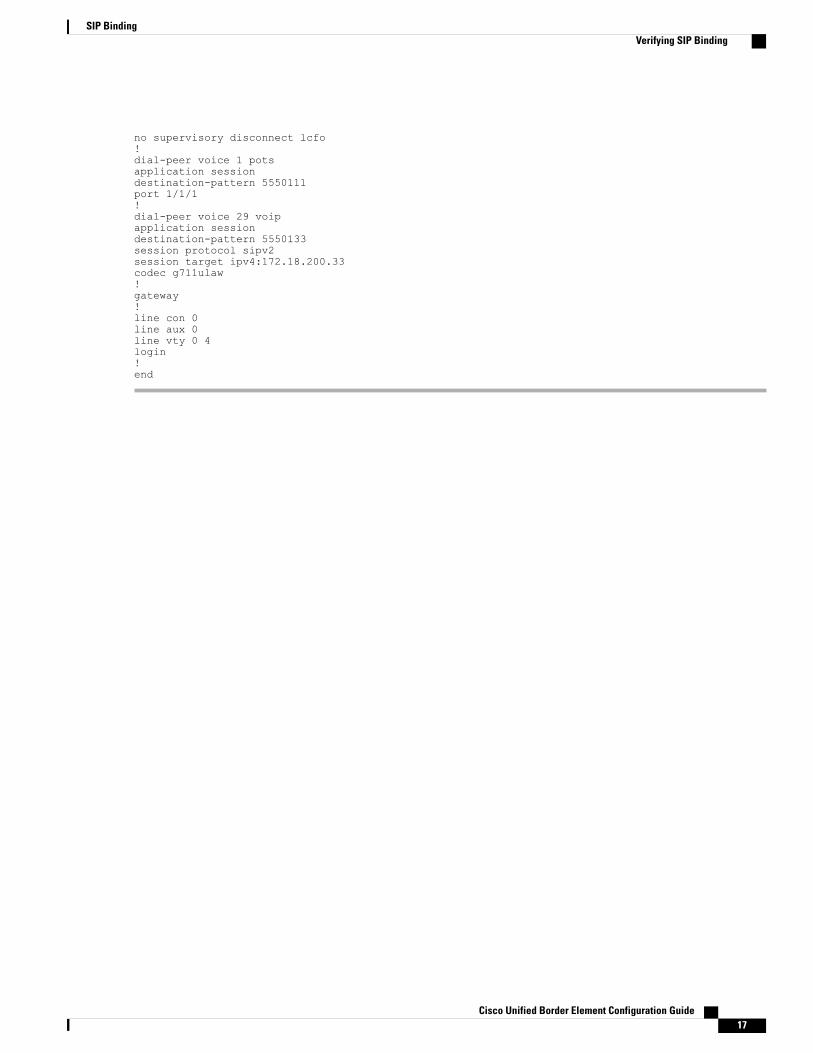
no supervisory disconnect lcfo!dial-peer voice 1 potsapplication sessiondestination-pattern 5550111port 1/1/1!dial-peer voice 29 voipapplication sessiondestination-pattern 5550133session protocol sipv2session target ipv4:172.18.200.33codec g711ulaw!gateway!line con 0line aux 0line vty 0 4login!end
Cisco Unified Border Element Configuration Guide 17
SIP BindingVerifying SIP Binding

Cisco Unified Border Element Configuration Guide18
SIP BindingVerifying SIP Binding