Embed Size (px)
Citation preview
SINTERING
AND
PELLETISATION
OF
INDIAN IRON ORES
By
SURESH KUMAR* & T.M. SRINIVASAN**
* Vice President, Mineral Enterprises Limited, Bangalore
** Managing Director, FerroGreen Technologies Pvt. Ltd. Bangalore
1
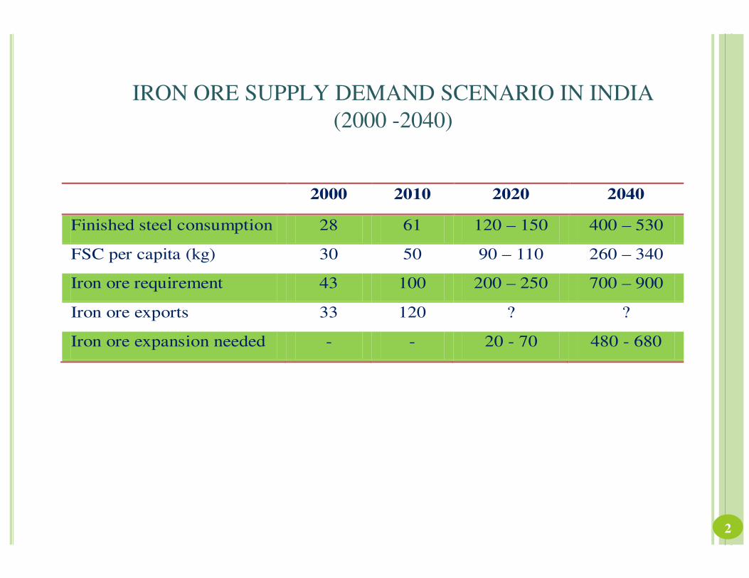
IRON ORE SUPPLY DEMAND SCENARIO IN INDIA
(2000 -2040)
2000 2010 2020 2040
Finished steel consumption 28 61 120 – 150 400 – 530
FSC per capita (kg) 30 50 90 – 110 260 – 340
Iron ore requirement 43 100 200 – 250 700 – 900
Iron ore exports 33 120 ? ?
Iron ore expansion needed - - 20 - 70 480 - 680
2
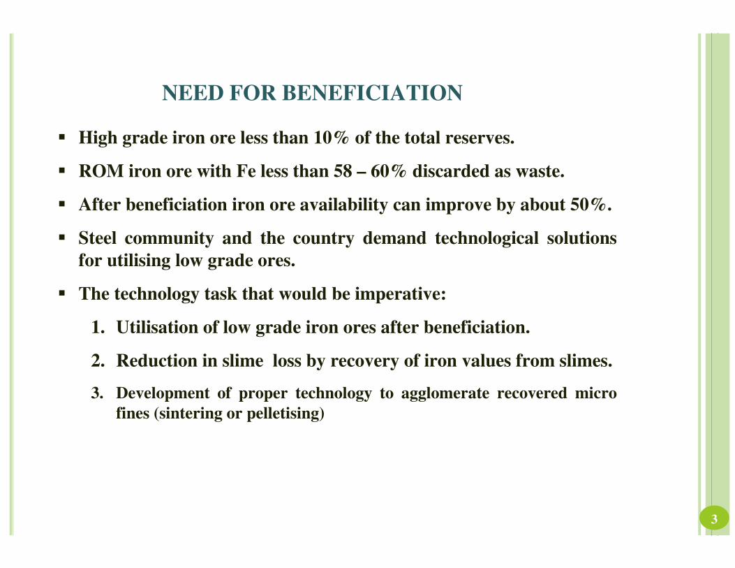
NEED FOR BENEFICIATION
� High grade iron ore less than 10% of the total reserves.
� ROM iron ore with Fe less than 58 – 60% discarded as waste.
� After beneficiation iron ore availability can improve by about 50%.
� Steel community and the country demand technological solutions
for utilising low grade ores.
� The technology task that would be imperative:
1. Utilisation of low grade iron ores after beneficiation.
2. Reduction in slime loss by recovery of iron values from slimes.
3. Development of proper technology to agglomerate recovered micro
fines (sintering or pelletising)
3
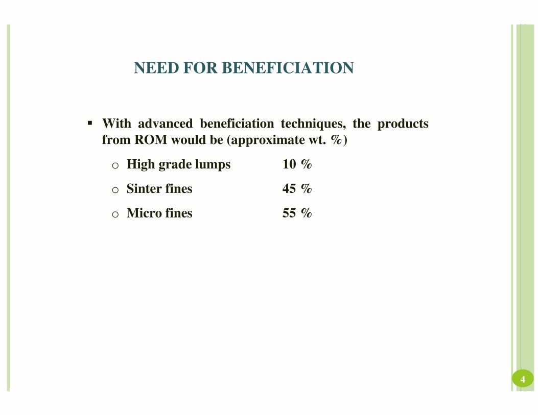
NEED FOR BENEFICIATION
� With advanced beneficiation techniques, the products
from ROM would be (approximate wt. %)
o High grade lumps 10 %
o Sinter fines 45 %
o Micro fines 55 %
4
AGGLOMERATION (Sintering & Pelletising)
� Common methods of burden preparation related to the
performance improvements of iron making (blast
furnaces & direct reduction process)
� Growth of steel industry with depleting resources of high
grade ores have led to a very strong demand for both
pelletising and sintering of iron ores.
5
PELLETISATION
� Process objective is to transform fine iron ore concentrate
into pellets suitable to feed Blast Furnace or Direct
Reduction plant or COREX.
� Pelletisation was invented to make use of Blue dust and
ultra fine concentrate generated in the Iron ore
beneficiation plants.
� Pellets have the benefit of lower gangue on account of
beneficiated ore.
6
NEED FOR PELLETISATION
� Steep rise in the prices of raw materials for DRI & Pig Iron
production
� Catering to the iron ore demands of all the DR/ Steel plants in
the country
� Good productivity, product quality and reasonable campaign
life is very important amongst fierce competition and low
grade iron ore availability.
� To meet ever increasing demand for iron ore with growth in
Steel i.e. 110 million tones by 2020
� Improved productivity and efficiency of the rotary kiln &
Blast Furnace with superior reducibility behaviour of pellets
compared to lump ore.
7
ADVANTAGE OF USING PELLETS IN DR KILNS
� 20-30% increase in production from rotary kiln
� Reduction in specific consumption of coal
� Longer campaign life due to less accretion
� Refractory repairing cost will reduce as there will be
no accretion and no fused lump formation,.
� Metallization will be better compared to lump ore.
� There will be very much less fines in the product as
against with lump ore.
� No need for crushing and screening of iron ore and
resultant fines disposal problem
� No losses in handling iron ore as PELLETS will not
break during transport or handling.
8
ADVANTAGE OF USING PELLETS IN BLAST FURNACE
� Improved productivity
� Reduced specific consumption of Coke especially with PCI
(widely practiced in most of the Chinese Mini Blast Furnaces)
� The charge mix is 40: 60 ratio instead of 100% sized ore
� 0-5 mm fines can be utilized & charged instead of rejecting.
� Lower blast pressure required can be met by indigenous
Centrifugal Fans in series due to Pellets of 10-20 mm instead of
High Blast Pressure by Turbo Blower because of 10-40 mm lump
ore
� No losses in handling iron ore as pellets will not break during
transport or handling.
9
TYPES OF PELLETISATION PROCESS
1. Grate kiln process
2. Travelling grate process.
Choice of one over the other will be based
more on economics rather than the
technical aspects
10
GRATE KILN PROCESS
� Process adopts three equipment viz. grate, rotary kiln and annular cooler.
� Green balls are first dried and preheated on the straight grate followed by
hardening in a counter flow manner in rotary kiln and air cooling in an
annular cooler
� The grate has two or more wind boxes to provide for the gas draft
� Heat for drying and preheating is supplied by the gases discharged from the
rotary kiln, and hot air from the cooler is utilised in the rotary kiln
� The pellet bed on the grate is only 150 -200 mm deep, and no protective
layer is required on the grate since it is subjected to low temperatures.
� The firing in rotary kiln lasts longer and the material is cooled bycooling air
passing through a relatively deep bed (0.8 – 1.0 m) of pellets.
11
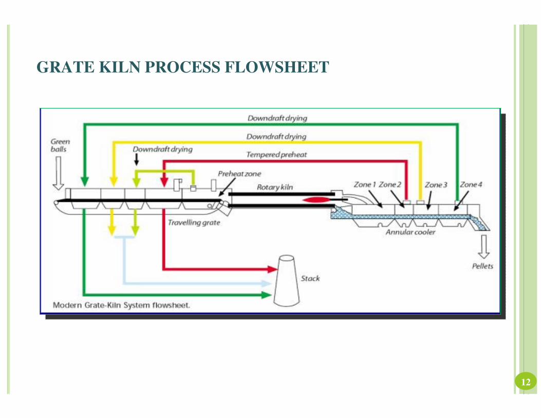
GRATE KILN PROCESS FLOWSHEET
12
CURRENT TRENDS IN GRATE-KILN PLANTS
� CFD designs Computational Fluid Dynamics analysis helped to reduce pressure
drop in the system reducing power requirement
� Balling drum size Size has been increased to 5 m dia with an output of over 200
TPH of net green balls
� Higher availability Use of specialty alloys for Grate parts and annular cooler parts
leading to higher reliability and reduced maintenance cost
� Fuel reduction Computerised Heat & Mass balance has been developed in close
interactions with existing high efficiency Grate-Kiln plant operators
� VFD drives for the fans Variable Frequency Drives are expected to save 20%
power and help to achieve exact control of process
13
FUTURE DEVELOPMENTS IN GRATE KILN PROCESS
Predictive Control Systems
OCS software combines expert system, fuzzy logic,
adaptive model structure, neural networks, statistic
functions etc. If incorporated OCS software can predict
the pellet qualities in advance or can produce pellets
meeting desired norms like fuel consumption, pollution
norms etc. OCS software optimises the plant
performance on a continuous basis, correlates changes
continuously and makes corrections online
14
TRAVELLING GRATE PROCESS
� Travelling grate machine used for induration of green pellets resembles the
well-known sintering machine of Dwight Lloyd design.
� Travelling grate machine is having completely closed hood with many
interconnected thermal zones for recirculation of [tpvrdd gas leading to
maximum heat recovery.
� The machine consists of three main parts;
a. Upper part comprises the heat energy and air supply system in a
stationary hood above the entire grate length with burner system in the
firing zone.
b. Bottom part is composed of the stationary wind boxes connected with
gas mains.
c. Central part is movable and consists of pallets, composed of a frame
and a supporting structure into which grate bars are inserted. The
pallets are connected to the wind boxes by means of sliding seal bars in
a gas tight manner.
15
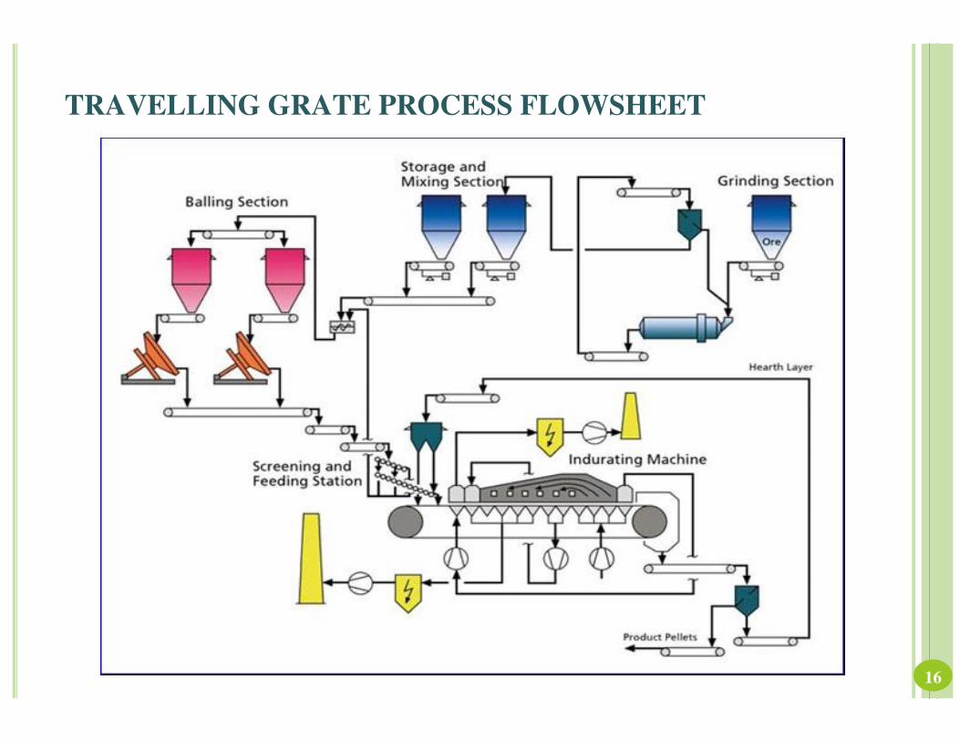
TRAVELLING GRATE PROCESS FLOWSHEET
16
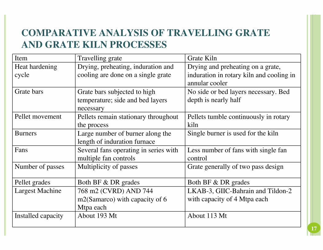
COMPARATIVE ANALYSIS OF TRAVELLING GRATE
AND GRATE KILN PROCESSES
17
Item Travelling grate Grate Kiln
Heat hardening
cycle
Drying, preheating, induration and
cooling are done on a single grate
Drying and preheating on a grate,
induration in rotary kiln and cooling in
annular cooler
Grate bars Grate bars subjected to high
temperature; side and bed layers
necessary
No side or bed layers necessary. Bed
depth is nearly half
Pellet movement Pellets remain stationary throughout
the process
Pellets tumble continuously in rotary
kiln
Burners Large number of burner along the
length of induration furnace
Single burner is used for the kiln
Fans Several fans operating in series with
multiple fan controls
Less number of fans with single fan
control
Number of passes Multiplicity of passes Grate generally of two pass design
Pellet grades Both BF & DR grades Both BF & DR grades
Largest Machine 768 m2 (CVRD) AND 744
m2(Samarco) with capacity of 6
Mtpa each
LKAB-3, GIIC-Bahrain and Tildon-2
with capacity of 4 Mtpa each
Installed capacity About 193 Mt About 113 Mt
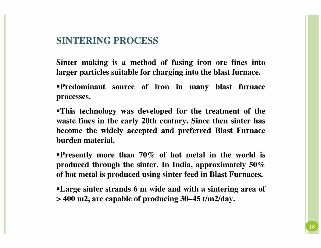
SINTERING PROCESS
Sinter making is a method of fusing iron ore fines into
larger particles suitable for charging into the blast furnace.
�Predominant source of iron in many blast furnace
processes.
�This technology was developed for the treatment of the
waste fines in the early 20th century. Since then sinter has
become the widely accepted and preferred Blast Furnace
burden material.
�Presently more than 70% of hot metal in the world is
produced through the sinter. In India, approximately 50%
of hot metal is produced using sinter feed in Blast Furnaces.
�Large sinter strands 6 m wide and with a sintering area of
> 400 m2, are capable of producing 30–45 t/m2/day.
18
SINTERING PROCESS
The major advantages of using sinter in BFs are
�Use of iron ore fines, coke breeze, metallurgical wastes, lime,
dolomite for hot metal production
�Better reducibility and other high temperature properties
�Increased BF productivity due to higher softening temperature
and lower softening –melting temperature range.
�Improved quality of hot metal
�Reduction in coke rate in blast furnaces.
19
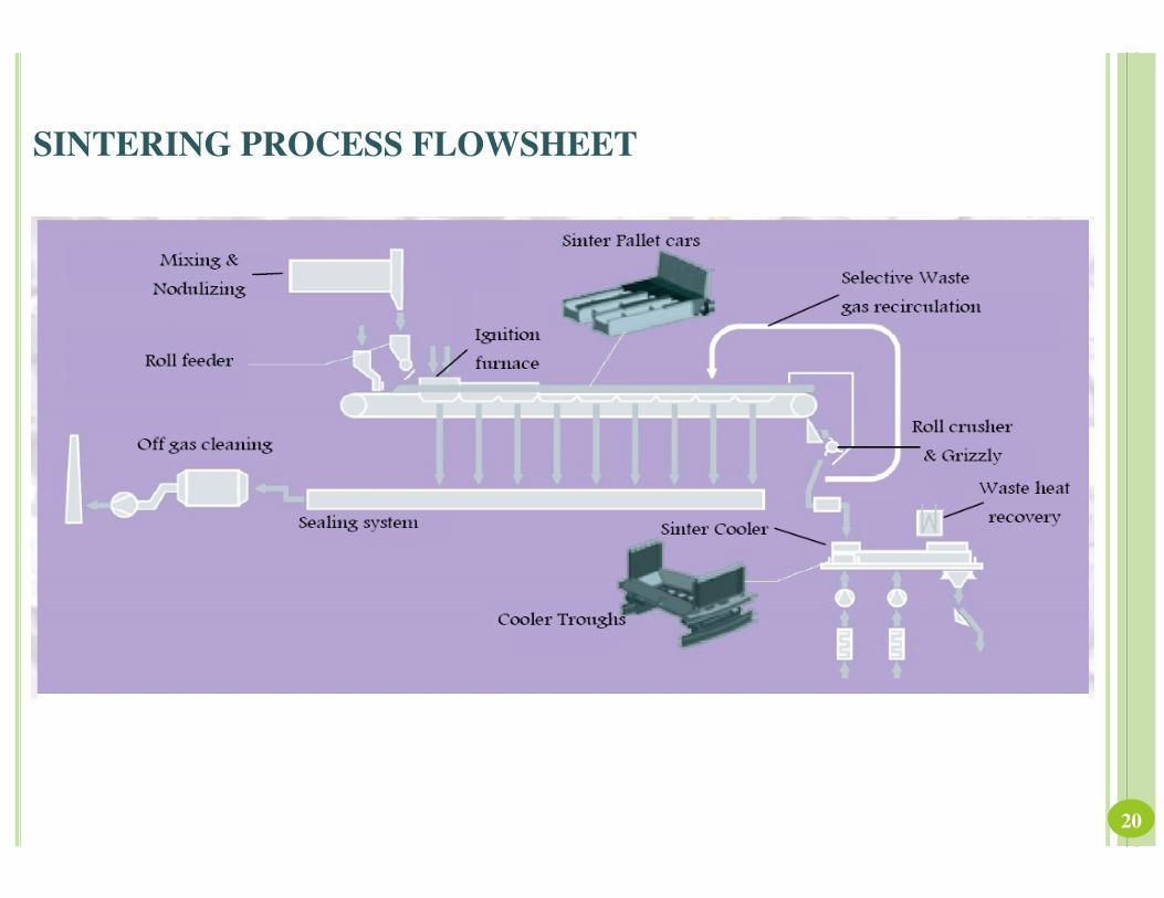
SINTERING PROCESS FLOWSHEET
20
SINTERING TECHNOLOGY IMPROVEMENTS
� High intensity mixing and nodulizing
� Ignition furnace for optimum maintenance and operation
� Travelling Grate with longer lasting pallets
� Minimized off-gas volumes with effective sealing.
� Reduction in off-gas cleaning capacity through Selective Waste Gas
Recirculation
� Discharge station for long service life
� Direct charging to cooler with maintenance-free cascade classifier for
natural segregation and improved cooling efficiency and reduced
emissions
� Efficient sinter cooling and installation of heat recovery system
� Energy savings together with reduced emissions
� Sinter plant control systems
21
HYBRID PELLETIZED SINTERING
HPS is characterized by micro pellets with high
mechanical strength, measuring between 2 mm and
8 mm. HPS feed consists of iron ore as pellet feed
fines, return fines and iron and steel work
remnants, filter dust, additives and binders like
limestone, dolomite, bentonite and coal dust. These
micro pellets are fed onto a sinter machine to
produce sinter cake, which is then broken down
and smelted in a blast furnace.
22
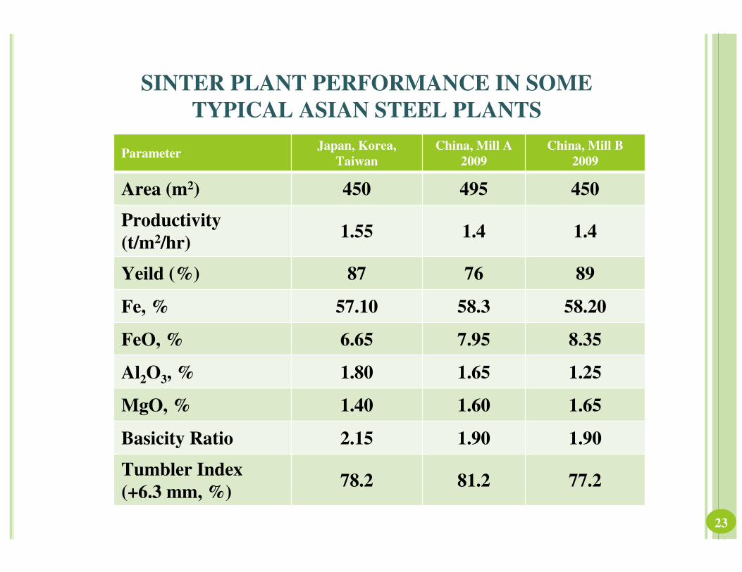
SINTER PLANT PERFORMANCE IN SOME
TYPICAL ASIAN STEEL PLANTS
23
ParameterJapan, Korea,
Taiwan
China, Mill A
2009
China, Mill B
2009
Area (m2) 450 495 450
Productivity
(t/m2/hr)1.55 1.4 1.4
Yeild (%) 87 76 89
Fe, % 57.10 58.3 58.20
FeO, % 6.65 7.95 8.35
Al2O3, % 1.80 1.65 1.25
MgO, % 1.40 1.60 1.65
Basicity Ratio 2.15 1.90 1.90
Tumbler Index
(+6.3 mm, %)78.2 81.2 77.2
FUTURE OF SINTERING AND
PELLETISING
� The future of sintering and pelletising is directly related to the
future of the iron making processes that use sinter and pellets,
mainly the Blast furnace and DR process.
� The future of these processes in turn depends upon steel
production and consumption, which have been on an upward
trend.
� Environmental interest
� Commitments to minimise CO2 emission mainly by striving to
minimise overall energy consumption.
24
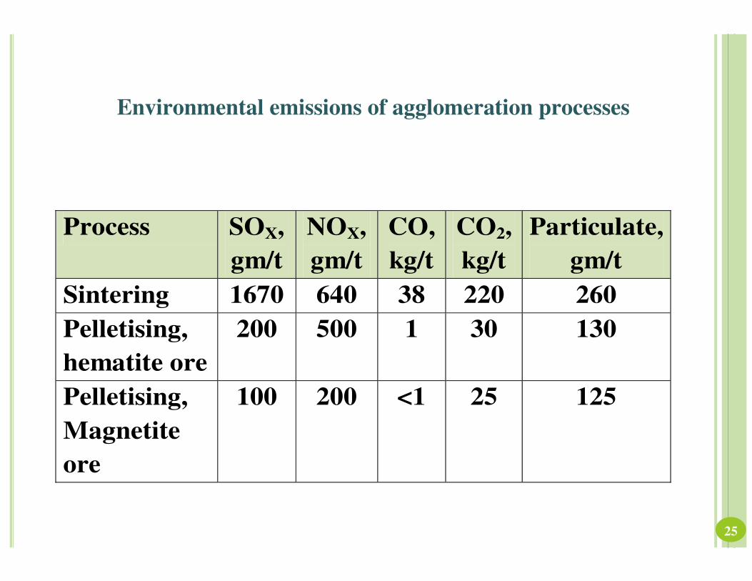
Environmental emissions of agglomeration processes
Process SOX,
gm/t
NOX,
gm/t
CO,
kg/t
CO2,
kg/t
Particulate,
gm/t
Sintering 1670 640 38 220 260
Pelletising,
hematite ore
200 500 1 30 130
Pelletising,
Magnetite
ore
100 200 <1 25 125
25
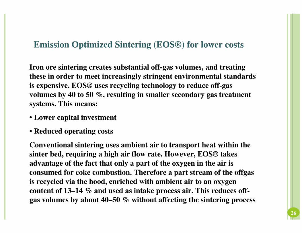
Emission Optimized Sintering (EOS®) for lower costs
Iron ore sintering creates substantial off-gas volumes, and treating
these in order to meet increasingly stringent environmental standards
is expensive. EOS® uses recycling technology to reduce off-gas
volumes by 40 to 50 %, resulting in smaller secondary gas treatment
systems. This means:
• Lower capital investment
• Reduced operating costs
Conventional sintering uses ambient air to transport heat within the
sinter bed, requiring a high air flow rate. However, EOS® takes
advantage of the fact that only a part of the oxygen in the air is
consumed for coke combustion. Therefore a part stream of the offgas
is recycled via the hood, enriched with ambient air to an oxygen
content of 13–14 % and used as intake process air. This reduces off-
gas volumes by about 40–50 % without affecting the sintering process
26
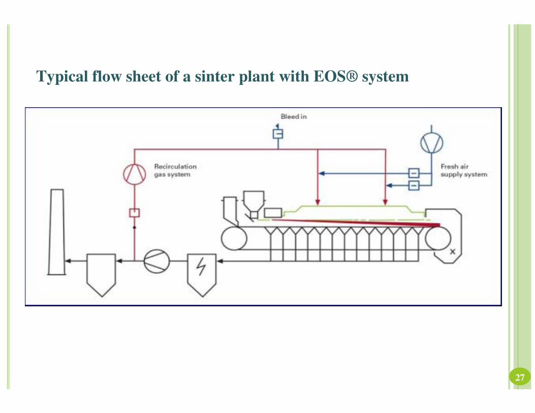
Typical flow sheet of a sinter plant with EOS® system
27
CONCLUSIONS:
• Indian economy is growing at 8-9% currently and likely to grow at rates
>10%.
• Steel demand and supply will grow in the same way riding piggyback on the
growing infrastructure.
• India is likely to develop a steel making capacity of 120-150 MTPA by the
year 2020 and around 400 MTPA by the year 2040.
• Since good iron ore deposits are depleting fast beneficiation technologies will
have to be adopted to meet iron ore demand.
• Agglomeration technologies such as pelletisation and sintering will have to
be added to Indian steel plants so that concentrates can be used and the
agglomerated products used in iron making to produce iron and steel
economically and in eco-friendly way. Existing sinter plants need to be
upgraded to use concentrate.
• The Agglomeration technologies are constantly being upgraded to meet
stringent environment standards. The same need to be incorporated in
existing units to make these more eco-friendly.28

THANK YOU
29