Embed Size (px)
Citation preview
User manual
Single-unit UPS
Modular UPS
Parallel UPS with SSC
Frequency converter
Static Switch Cubicle
MGETM GalaxyTM 900050, 60 Hz800 - 900 kVA

34006452EN/AC - Page 2
34006452EN/AC - Page 3
Contents
1. Introduction 1.1 System performance ................................................................................................................... 5
1.2 System description ...................................................................................................................... 5
1.3 Different types of MGETM GalaxyTM 9000 systems ................................................................. 6
1.4 Isolation and protection devices ................................................................................................. 8
UPS or converter cubicles (figure 8) ...............................................................................................................8
Static Switch Cubicle (figure 9) .......................................................................................................................8
External maintenance bypass cubicle (figure 10) ............................................................................................9
1.5 Main operating modes .................................................................................................................. 9
Normal operation .............................................................................................................................................9
Operation with Mains 1 down (figure 12) .......................................................................................................10
Battery time ....................................................................................................................................................10
Operation with Mains 1 restored (figure 13) ..................................................................................................11
Installation with an engine generator set (figure 15) ...................................................................................12
Output voltage quality and continuity .............................................................................................................13
2. Description of MGETM GalaxyTM 9000 cubicles 2.1 Inverter cubicle .......................................................................................................................... 14
2.2 Static Switch Cubicle ................................................................................................................ 15
2.3 External maintenance bypass cubicle .................................................................................... 15
3. Control panel 3.1 Visible control panel .................................................................................................................. 17
3.2 Hidden control panel ................................................................................................................. 20
4. Start-up 4.1 System start-up ........................................................................................................................... 23
Single-unit or modular UPS ...........................................................................................................................23
Multi-bypass modular UPS ............................................................................................................................24
Modular UPS with external maintenance bypass ..........................................................................................25
Frequency converters ....................................................................................................................................26
Parallel UPS systems with a Static Switch Cubicle ........................................................................................27
4.2 Start-up of a unit ......................................................................................................................... 27
Start-up of a rectifier/charger .........................................................................................................................27
Start-up of an inverter ....................................................................................................................................27
5. Shutdown 5.1 Shutdown of a unit ...................................................................................................................... 28
Shutdown of an inverter .................................................................................................................................28
Shutdown of an rectifier/charger ....................................................................................................................29
5.2 System shutdown ....................................................................................................................... 29
Single-unit or single modular UPS .................................................................................................................29
Modular UPS with external maintenance bypass ..........................................................................................30
Multi-bypass modular UPS .............................................................................................................................30
Frequency converters (no Mains 2) ..............................................................................................................30
Parallel UPSs with SSC (with Mains 2) ..........................................................................................................31
5.3 Buzzer reset ................................................................................................................................ 31
6. Alarms 6.1 Maintenance bypass .................................................................................................................. 32
7. Environment information 7.1 Standard information Media Contacts 9 .................................................................................. 33
Signal reception .............................................................................................................................................33
Signal transmission ........................................................................................................................................33
34006452EN/AC - Page 4
Contents
7.2 "LED" signalling box (optional) ..................................................................................................34
7.3 Additional information "Media Contacts 15" ..........................................................................34
Signal reception ............................................................................................................................................. 35
Signal transmission ....................................................................................................................................... 35
8. Maintenance 8.1 Maintenance configuration .........................................................................................................36
Single-unit or single modular UPS (figure 25) .............................................................................................. 36
Multi-bypass modular UPS (figure 26) ......................................................................................................... 36
Modular UPS with external maintenance bypass (figure 27) ........................................................................ 37
Frequency converter or parallel UPS with SSC (figure 28) ............................................................................ 38
Static Switch Cubicle (figure 29) ..................................................................................................................... 38
8.2 Battery maintenance ..................................................................................................................39
8.3 Autodiagnostics ..........................................................................................................................39
8.4 Visual check ................................................................................................................................39
8.5 Functional check ........................................................................................................................39
8.6 Training centres ...........................................................................................................................40
9. "Monitor" alphanumeric display 9.1 General ........................................................................................................................................41
Display ........................................................................................................................................................... 41
9.2 Control panel ...............................................................................................................................42
9.3 Lights 1 to 8 .................................................................................................................................43
9.4 Alarm display and buzzer reset .................................................................................................44
List of general alarms .................................................................................................................................... 44
List of secondary alarms ............................................................................................................................... 45
9.5 Measurement system .................................................................................................................50
9.6 Voltage measurements ...............................................................................................................51
9.7 Current measurements ..............................................................................................................52
9.8 Frequency and power measurements ......................................................................................53
9.9 Battery measurements ...............................................................................................................54
9.10 Inverter On/Off commands ......................................................................................................56
9.11 Language, display contrast and buzzer volume settings .....................................................57
9.12 Display system configuration ..................................................................................................58
10. Options 10.1 "LED" signalling box ................................................................................................................59
10.2 "Tele-Monitor" remote indications unit ..................................................................................59
10.3 "GTC link" communications system .......................................................................................59
10.4 "Vision" display ........................................................................................................................60
10.5 "Remote vision" display ..........................................................................................................60
10.6 Insulating and Mains 1, Mains 2 and load voltage matching transformer ...........................60
10.7 Double bridge rectifier-charger ...............................................................................................61
10.8 Battery "Temperature Monitor" ...............................................................................................61
10.9 Empty cubicles ........................................................................................................................61

34006452EN/AC - Page 5
1. Introduction
1.1 System performance
Single-line diagram of the MGETM GalaxyTM 9000 system
1.2 System description
A MGETM GalaxyTM 9000 uninterruptible power supply (UPS) delivers 3-phase power with the following characteristics:– stable voltage (±0.5 % under steady state conditions and +/-5% under transient conditions for load step changes of 25 to 100 % or of 100 to 25 %);– stable frequency (±0.05Hz without Mains 2);– or frequency synchronized with Mains 2 to 50/60 Hz ±2 Hz (value may be configured in 0.25 Hz steps);– free of micro-breaks and outages for the duration of the battery time (10, 15 or 30 minutes);– less than 4 % distortion in all system configurations with linear loads;– less than 5 % distortion for a 100 % non-linear load with a peak factor of up to 3.5.The acoustic noise level of a MGETM GalaxyTM 9000 UPS is under 75 dBA.
– a rectifier-charger (RC) module converts 3-phase AC power from the Mains 1 supply into DC power for the normal inverter input and float charges or recharges the batteries;– a battery unit provides backup power for the inverter in the event of a voltage drop or a Mains 1 failure;– an inverter module converts the DC power supplied by the rectifier-charger module or the battery unit into 3-phase AC power for the load;– an emergency bypass module ensures the instantaneous transfer of the load via the static switch to the Mains 2 bypass line in the event of an inverter shutdown (initiated by the user or by a protective device) or a sudden overload;– a maintenance bypass which isolates the UPS for maintenance and transfers the load without interrupting the supply of power. The maintenance bypass is made up of three manual switches.Note:– the Mains 1 normal input and the Mains 2 bypass input have different functions and, depending on the installation, may be protected differently upstream and/or come from different sources;– frequency converters are available without backup batteries;– the emergency bypass line and the maintenance bypass line do not exist in installations where the load frequency and the Mains 2 frequency are different (for example in frequency converters);– for reasons of redundancy and/or increased power, the rectifier-charger, inverter and battery modules (the UPS, part A in the MGETM GalaxyTM 9000 schematic diagram above) may be arranged in parallel lines. In this case, an isolation function is added to the output of each UPS for maintenance without disrupting the load. In this type of system, the components of part B in the diagram are located in a separate cubicle referred to as the "Static Switch Cubicle".
The system may also include:– an isolating transformer on the Mains 2 line;– a harmonics filter on the Mains 1 input;– different remote control, indication and display systems;– a double bridge rectifier-charger module.
���������������
���� �������
���������������
���������
���������������������
���������������
����������������������
������
����
�������������� ���
��������� ����� ���
�
�
���������������������

34006452EN/AC - Page 6
Introduction
1.3 Different types of MGETM GalaxyTM 9000 systems – Single-unit or modular UPS: (figure 1)
Fig. 1
– Multi-bypass modular UPSs: (figure 2)
Note: 2 modular UPSs (identical ratings) can be parallel-connected in this way.
Fig. 2
– Modular UPSs with external maintenance bypass: (figure 3)
Note: Up to 4 UPS (identical ratings) can be parallel-connected.
Fig. 3
�������
�������������� ��
������
��������
����
�������������
�������
���
�������
�������������� ��
������
��������
����
�������������
�������
�������
�������������� ��
������
��������
�������������
�������
���
���
���
�!"
�������
�������������� ��
������
��������
����
�������������
�������
�������
�������������� ��
������
��������
�������������
�������
34006452EN/AC - Page 7
Introduction
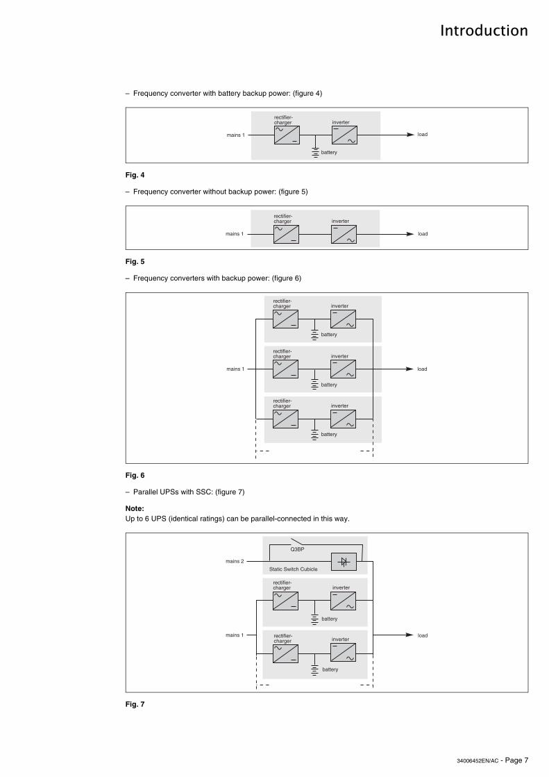
– Frequency converter with battery backup power: (figure 4)
Fig. 4
– Frequency converter without backup power: (figure 5)
Fig. 5
– Frequency converters with backup power: (figure 6)
Fig. 6
– Parallel UPSs with SSC: (figure 7)
Note: Up to 6 UPS (identical ratings) can be parallel-connected in this way.
Fig. 7
�������
�������������� ��
������
��������
����
�������
�������������� �� ��������
����
�������
�������������� �� ��������
����
������
�������������� �� ��������
������
�������������� �� ��������
������
#������#�������$�����
���
�������������� ��
������
��������
������� �������������� ��
������
������������
�������
34006452EN/AC - Page 8
Introduction
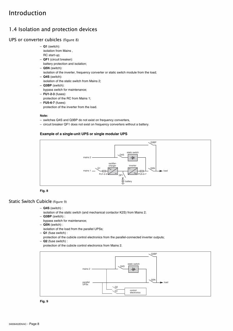
1.4 Isolation and protection devices
UPS or converter cubicles (figure 8)
Example of a single-unit UPS or single modular UPS
Static Switch Cubicle (figure 9)
– Q1 (switch): isolation from Mains ,RC start-up;
– QF1 (circuit breaker): battery protection and isolation;
– Q5N (switch): isolation of the inverter, frequency converter or static switch module from the load;
– Q4S (switch): isolation of the static switch from Mains 2;
– Q3BP (switch): bypass switch for maintenance;
– FU1-2-3 (fuses): protection of the RC from Mains 1;
– FU5-6-7 (fuses): protection of the inverter from the load.
Note:– switches Q4S and Q3BP do not exist on frequency converters,– circuit breaker QF1 does not exist on frequency converters without a battery.
Fig. 8
– Q4S (switch) :isolation of the static switch (and mechanical contactor K2S) from Mains 2;
– Q3BP (switch) :bypass switch for maintenance;
– Q5N (switch) :isolation of the load from the parallel UPSs;
– Q1 (fuse switch) :protection of the cubicle control electronics from the parallel-connected inverter outputs;
– Q2 (fuse switch) :protection of the cubicle control electronics from Mains 2.
Fig. 9
������� ����
�������������� ��
������
��������
�������������
�������
�� �!"
�%�%&����� %&!�'�(
���
�)#
�������& #�
����
�������������
�������
��
�!"
���
�)#
������������������
��

34006452EN/AC - Page 9
Introduction
External maintenance bypass cubicle (figure 10)
1.5 Main operating modes
Normal operation
– Q3BP (switch) :bypass switch for maintenance;
– Q5N (switch) :isolation of the load from the parallel-connected UPSs.
Fig. 10
Mains 1 power is available: (see figure 11).The green "load protected" light on the control panel is on.
The power necessary for the load is provided by Mains 1 through the rectifier-charger and the inverter.The rectifier-charger also supplies the power to float charge and recharge the battery (1). The rectifier-charger output voltage (DC) is regulated for the different battery types and charging modes:– vented lead-acid or Ni/Cd batteries: two different voltages, one for float charging and one for recharging;– sealed lead-acid batteries: a single voltage for both charge functions.The voltages depend on the number of battery cells and the battery manufacturer. They can be factory set and are adjustable by the after-sales support technicians.An optional electronic board may be used to continuously measure the battery temperature and automatically adjust the voltages.
Parallel UPS systems:the power drawn by the load is equally shared between the different UPSs.
(1) Except for frequency converters without a battery
Fig. 11
�!"
���
����������$����& #�
����
��������������������
5
������� ��� ��
�
*+ ,�� -
�������
�������������� ��
������
��������
����
�������������
�������

34006452EN/AC - Page 10
Introduction
Operation with Mains 1 down (figure 12)
Battery time
In the event of a Mains 1 failure or Mains 1 voltage outside specified tolerance of –10 % in amplitude (–15 % optionally), the rectifier-charger stops and the battery supplies the necessary backup power to the load via the inverter. The battery, float-connected between the rectifier-charger and the inverter, discharges during this operating mode.The green "load protected" light on the control panel is on.The user is warned of battery operation by a buzzer and the orange "load on battery" light on the control panel.
This information is also available via volt-free changeover contacts for remote control devices.In this case, there is a 30 seconds delay.
Note:In the event of a Mains 1 failure, frequency converters without a battery shut down and the load is no longer supplied.
Fig. 12
The available battery time during a Mains 1 outage depends on the:– rated capacity of the battery;– power consumed by the load;– temperature of the battery;– age of the battery.The specified battery time corresponds to a minimum duration at full rated load.The actual backup time can therefore be greater if the system operates below its full rated load during the Mains 1 outage. Operation on battery power can be extended beyond the specified time by reducing the load power consumption (by disconnecting non-critical loads).A "low battery shutdown" warning signal is sent via volt-free changeover contacts for remote control devices when the battery voltage reaches a level slightly above the minimum level. This signal warns the user of the imminent end of battery power. On the device itself, the buzzer beeps increasingly rapidly and loudly.Battery power stops when the voltage supplied by the battery reaches the voltage minimum (340 V). This results in inverter shutdown and transfer of the load without interruption to Mains 2. The red "load not protected" light on the control panel is on.
If Mains 2 also fails, the load is no longer supplied. Normally, the inverter shuts down when the time on the battery power exceeds three times the specified backup time.
Note:As an optional function (battery time estimator), the "low battery shutdown" warning signal can be sent with an adjustable time delay prior to the effective end of battery power.
54
�
*+ ,�� -
�
���...���...
�������
�������������� ��
������
��������
����
�������������
�������
2
*+ ,�� -
�
���...���...
34006452EN/AC - Page 11
Introduction
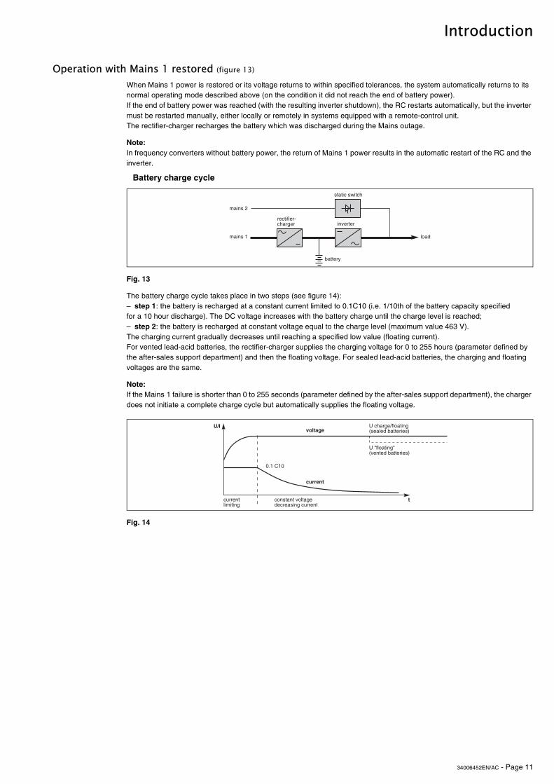
Operation with Mains 1 restored (figure 13)
Battery charge cycle
When Mains 1 power is restored or its voltage returns to within specified tolerances, the system automatically returns to its normal operating mode described above (on the condition it did not reach the end of battery power). If the end of battery power was reached (with the resulting inverter shutdown), the RC restarts automatically, but the inverter must be restarted manually, either locally or remotely in systems equipped with a remote-control unit.The rectifier-charger recharges the battery which was discharged during the Mains outage.
Note:In frequency converters without battery power, the return of Mains 1 power results in the automatic restart of the RC and the inverter.
Fig. 13
The battery charge cycle takes place in two steps (see figure 14):– step 1: the battery is recharged at a constant current limited to 0.1C10 (i.e. 1/10th of the battery capacity specified for a 10 hour discharge). The DC voltage increases with the battery charge until the charge level is reached;– step 2: the battery is recharged at constant voltage equal to the charge level (maximum value 463 V). The charging current gradually decreases until reaching a specified low value (floating current).For vented lead-acid batteries, the rectifier-charger supplies the charging voltage for 0 to 255 hours (parameter defined by the after-sales support department) and then the floating voltage. For sealed lead-acid batteries, the charging and floating voltages are the same.
Note: If the Mains 1 failure is shorter than 0 to 255 seconds (parameter defined by the after-sales support department), the charger does not initiate a complete charge cycle but automatically supplies the floating voltage.
Fig. 14
�������
�������������� ��
������
��������
����
�������������
�������
��
�$������������
/.����/
�������������� ���������� ��$�����
!������
"������
�
&����� ��������� 0����������������1
&�2������� 20����������������1
34006452EN/AC - Page 12
Introduction
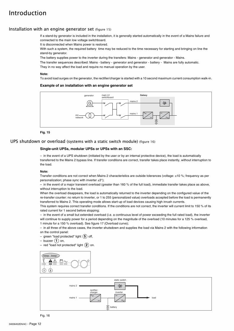
Installation with an engine generator set (figure 15)
UPS shutdown or overload (systems with a static switch module) (figure 16)
Single-unit UPSs, modular UPSs or UPSs with an SSC:
Fig. 16
If a stand-by generator is included in the installation, it is generally started automatically in the event of a Mains failure and connected to the main low voltage switchboard. It is disconnected when Mains power is restored.With such a system, the required battery time may be reduced to the time necessary for starting and bringing on line the stand-by generator.
The battery supplies power to the inverter during the transfers: Mains - generator and generator - Mains.
The transfer sequences described: Mains - battery - generator and generator - battery - Mains are fully automatic. They in no way affect the load and require no manual operation by the user.
Note:To avoid load surges on the generator, the rectifier/charger is started with a 10 second maximum current consumption walk-in.
Example of an installation with an engine generator set
Fig. 15
– in the event of a UPS shutdown (initiated by the user or by an internal protective device), the load is automatically transferred to the Mains 2 bypass line. If transfer conditions are correct, transfer takes place instantly, without interruption to the load.
Note: Transfer conditions are not correct when Mains 2 characteristics are outside tolerances (voltage: ±10 %; frequency as per personalization; phase sync with inverter ±3°);– in the event of a major transient overload (greater than 160 % of the full load), immediate transfer takes place as above, without interruption to the load.When the overload disappears, the load is automatically returned to the inverter depending on the configured value of there-transfer counter: no return to inverter, or 1 to 255 (personalized value) overloads accepted before the load is permanently transferred to Mains 2. This operating mode allows start-up of load devices causing high inrush currents.This system requires correct transfer conditions. If the conditions are not correct, the inverter will current limit to 150 % of its rated current for 1 second before stopping;– in the event of a small but extended overload (i.e. a continuous level of power exceeding the full rated load), the inverter will continue to supply power for a period depending on the magnitude of the overload (10 minutes for a 125 % overload, 1 minute for a 150 % overload). See figure 17 (Overload curve);– in all three of the above cases, the inverter shutsdown and supplies the load via Mains 2 with the following information on the control panel:– green "load protected" light off, – buzzer on, – red "load not protected" light on.
�������
�������
#���$�
3
�����45�����������
��������
65������7
51
2
*+ ,�� -
�
���...���...
�������
�������������� ��
������
��������
����
�������������
�������

34006452EN/AC - Page 13
Introduction
Frequency converters without redundancy
Frequency converters with redundancy
Overload curve
Fig. 17
Output voltage quality and continuity
Steady state voltage regulation:
Note:
Transient voltage regulation:
– in the event of a shutdown, the load is no longer supplied with power;– in the event of a major transient overload (greater than 160 % of the rated load), the inverters will current limit to 160 % of their rated current for 1 second before stopping;– in the event of a small but extended overload (i.e. a continuous level of power exceeding the full rated load), the inverters will continue to supply power for a period depending on the magnitude of the overload (10 minutes for a 125 % overload, 1 minute for a 150 % overload, see figure 17), and then stop;– in all three of the above cases, inverter shutdown results in the following on the control panel of the concerned unit:– green "load protected" light off,– buzzer on,– red "load not protected" light on.
– the shutdown of one unit is of no consequence for the load. The other lines each take up an equal amount of load power and the load continues to be supplied normally;Inverter shutdown results in the following on the control panel of the concerned unit:– green "load protected" light off,– buzzer on,– red "load not protected" light on.– in the event of an overload, the system only loses its redundancy as long as the overload is less than the total rated power of the functioning units. If the overload is greater, the operating mode is that previously described for systems without redundancy.
The output voltage is stable in amplitude and frequency and is free of interruptions or transients outside specified tolerances, irrespective of Mains 1 or load disturbances (outages, load step changes, etc.).
For stable or slowly varying load conditions, the inverter output voltage is regulated to within ±0.5 % in amplitude.The frequency of the output voltage can theoretically be regulated to within 0.1 % of the rated value, however the output frequency range may be intentionally extended to a maximum of ±2 Hz so that the inverter can remain synchronized with Mains 2 and its inherent frequency fluctuations, thus enabling transfer of the load to the bypass line at any time.
The output frequency range can be personalized and if necessary modified on the customer site by a qualified support technician from ±0.25 Hz to ±2 Hz in 0.25 Hz steps.When the Mains 2 voltage moves outside this frequency range, the inverter is desynchronized and operates in "free running" mode, with the output frequency regulated to a high level of accuracy by a quartz oscillator.When the Mains 2 frequency returns to within the specified tolerances, the inverter is gradually re-synchronized to the bypass line at a rate of 0.5 Hz to 2 Hz/s (as per the value personalized by the after-sales support department), thus avoiding exposing the load to sudden frequency variations.
The inverter output voltage is not notably affected by instantaneous major variations in load characteristics.This is due to the PWM (Pulse Width Modulation) chopping technique and the microprocessor-based regulation system that instantly compensates for any variation. In particular, the inverter output voltage remains within ±5 % of the rated voltage for load step changes of 25 to 100 % or of 100 to 25 %.
51
2
51
2
�
� � � � � � � � �
�����
������
������
�����
����� �
�� �� ��� �����

34006452EN/AC - Page 14
2. Description of MGETM GalaxyTM 9000 cubicles
2.1 Inverter cubicle
UPS or frequency converter
The rated outputs for MGETM GalaxyTM 9000 UPS’s (without parallel connection) or frequency converters are 800, 900 kVA.
Legend for figure 181 - rectifier-charger (RC) module2 - inverter stack modules3 - rack for electronic control boards4 - static switch module (Single-unit or modular UPS)4' - output static switch module (modular UPS, frequency converter or parallel UPS with SSC)5 - RC input fuses FU1-2-36 - Mains 1 input switch Q17 - protection fuses FU8 for the Mains 2 resistance/capacitance voltage surge protection network8 - Mains 2 input switch Q4S (Single-unit or modular UPS)9 - maintenance bypass switch Q3BP (Single-unit or modular UPS)10 - output switch Q5N11 - inverter output fuses FU 5-6-712 - "Media Contacts 9" remote indications board13 - additional "Media Contacts 15" remote indications board (optional).
Fig. 18
front view, doors open, protective covers removed
%
&
�'
�
%��
() *
��� ���
+

34006452EN/AC - Page 15
Description of MGETM GalaxyTM 9000 cubicles
2.2 Static Switch Cubicle
Fig. 19
2.3 External maintenance bypass cubicle
Fig. 20
Static Switch Cubicles are rated 500, 800, 1200 and 2000 kVA. Figure 19 presents the layout of components in these cubicles.
Legend for figure 19:
2 - Mains 2 input switch Q4S,3 - maintenance bypass switch Q3BP,4 - output switch Q5N,5 - static switch module,6 - electronic control boards for the backup function,7 - protection fuses FU1 for the Mains 2 resistance/capacitance voltage surge protection network,8 - fuse switch Q1 (protection of the control electronics power supply against Mains 1),9 - fuse switch Q2 (protection of the control electronics power supply against Mains 2),10 - "Media Contacts 9" remote indications board,11 - additional "Media Contacts 15" remote indications board (optional).
Legend for figure 20:1 - connection of auxiliary wires to indicate the positions of switches Q5N and Q3BP,2 - maintenance bypass switch Q3BP,3 - output switch Q5N.
front view, doors open, protective covers removed
)
�+
*&
�
%
�
(
�
+
�
�
%
�
) *&
(
�
%
�
&
+
) *
(
�
�((��)((,-�"���"�� �((,-�"���"��
�(((,-�"���"��
�((,-�"���"��
�
%
34006452EN/AC - Page 16
3. Control panel
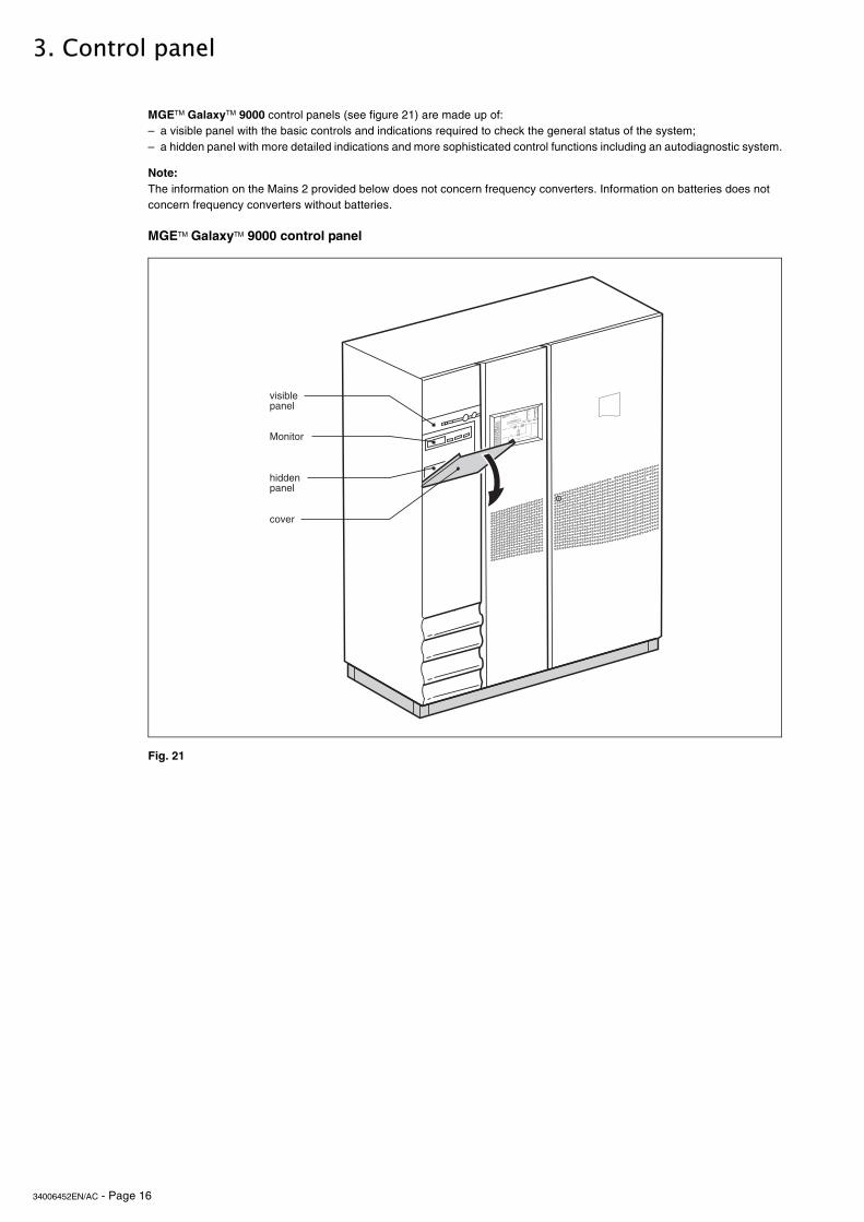
MGETM GalaxyTM 9000 control panel
Fig. 21
MGETM GalaxyTM 9000 control panels (see figure 21) are made up of:– a visible panel with the basic controls and indications required to check the general status of the system;– a hidden panel with more detailed indications and more sophisticated control functions including an autodiagnostic system.
Note:The information on the Mains 2 provided below does not concern frequency converters. Information on batteries does not concern frequency converters without batteries.
�����������
����������
�����
8������
�������������������
���� ���
��������������
����������
����
���
���
�
����������� !"����
���
�
�#� $�%$��&�����' (������$�#�$
)��(�$��*
&+��,,��*
�����-� �(�!�
��
��)
�.�
��
�/&0
��1�1/����/�2��2����
��(�
�$��(,
3!$ !�
'��!�
���� ,� �,
4��� 5 ��
&�����+
�!#�����
&+��,,
3�����
������
34006452EN/AC - Page 17
Control panel
3.1 Visible control panel
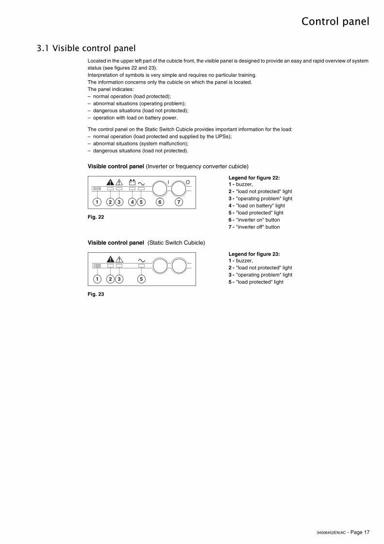
Visible control panel (Inverter or frequency converter cubicle)
Visible control panel (Static Switch Cubicle)
Fig. 23
Located in the upper left part of the cubicle front, the visible panel is designed to provide an easy and rapid overview of system status (see figures 22 and 23).Interpretation of symbols is very simple and requires no particular training. The information concerns only the cubicle on which the panel is located.The panel indicates:– normal operation (load protected);– abnormal situations (operating problem);– dangerous situations (load not protected);– operation with load on battery power.
The control panel on the Static Switch Cubicle provides important information for the load:– normal operation (load protected and supplied by the UPSs);– abnormal situations (system malfunction);– dangerous situations (load not protected).
Legend for figure 22:1 - buzzer,2 - "load not protected" light3 - "operating problem" light4 - "load on battery" light5 - "load protected" light6 - "inverter on" button7 - "inverter off" button
Fig. 22
Legend for figure 23:1 - buzzer,2 - "load not protected" light3 - "operating problem" light5 - "load protected" light
�
*+ ,�� -
�%� + &
�
��
%�

34006452EN/AC - Page 18
Control panel
Buzzer
"Load not protected" light
"Operating problem" light
"Battery operation" light
The buzzer sounds in the following situations:– load supplied by Mains 2;– load on battery;– operating problems.It beeps at a low decibel level and slow rate for minor problems and when the load is supplied from battery power. When the "low battery shutdown imminent" warning is received, the beeps increase in decibel level and rate. Finally, if the inverter shuts down, the beep is loud and continuous. A buzzer reset button is located on the hidden control panel. If the buzzer is reset, a higher level alarm will set it on again.
This red light signals that:– the load is supplied by Mains 2 following inverter shutdown (initiated by the user or by a protective device or a sudden overload) or the opening of the inverter output switch Q5N;– battery circuit breaker QF1 has opened, thus making battery power unavailable.
Note:In a parallel system, this light concerns only the specific UPS. The load may still be protected by the other lines.
This orange light signals an operating problem or an environment fault, however the load is still supplied by the inverter.– operating problems:
static switch ventilation fault,static switch control system fault;
– environment faults:battery temperature outside tolerances,overload greater than 5 %;
– Mains 2 up but with voltage, frequency or phase characteristics outside tolerances with regards to the inverter.
This blinking orange light signals that the load is on battery power following:– a Mains 1 outage or voltage drop;– insufficient power on Mains 1, for example power supplied by an engine generator set requiring additional battery power;– battery problem.
1
*+ ,�� -
���...���...
*+ ,�� -
�
2
*+ ,�� -
%
3
*+ ,�� -
�
4
34006452EN/AC - Page 19
Control panel
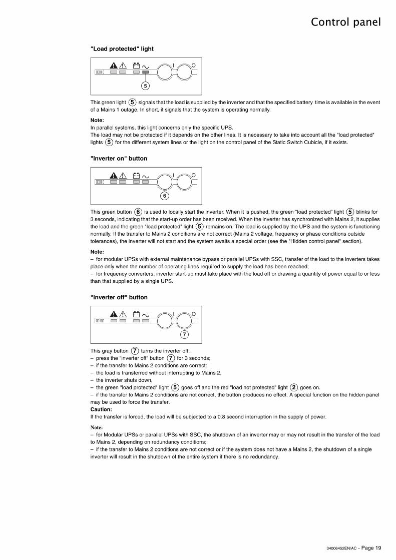
"Load protected" light
"Inverter on" button
"Inverter off" button
This green light signals that the load is supplied by the inverter and that the specified battery time is available in the event of a Mains 1 outage. In short, it signals that the system is operating normally.
Note:In parallel systems, this light concerns only the specific UPS.The load may not be protected if it depends on the other lines. It is necessary to take into account all the "load protected" lights for the different system lines or the light on the control panel of the Static Switch Cubicle, if it exists.
This green button is used to locally start the inverter. When it is pushed, the green "load protected" light blinks for 3 seconds, indicating that the start-up order has been received. When the inverter has synchronized with Mains 2, it supplies the load and the green "load protected" light remains on. The load is supplied by the UPS and the system is functioning normally. If the transfer to Mains 2 conditions are not correct (Mains 2 voltage, frequency or phase conditions outside tolerances), the inverter will not start and the system awaits a special order (see the "Hidden control panel" section).
Note:– for modular UPSs with external maintenance bypass or parallel UPSs with SSC, transfer of the load to the inverters takes place only when the number of operating lines required to supply the load has been reached;– for frequency converters, inverter start-up must take place with the load off or drawing a quantity of power equal to or less than that supplied by a single UPS.
This gray button turns the inverter off.– press the "inverter off" button for 3 seconds;– if the transfer to Mains 2 conditions are correct:– the load is transferred without interrupting to Mains 2,– the inverter shuts down,– the green "load protected" light goes off and the red "load not protected" light goes on.– if the transfer to Mains 2 conditions are not correct, the button produces no effect. A special function on the hidden panel may be used to force the transfer.Caution:If the transfer is forced, the load will be subjected to a 0.8 second interruption in the supply of power.
Note:– for Modular UPSs or parallel UPSs with SSC, the shutdown of an inverter may or may not result in the transfer of the load to Mains 2, depending on redundancy conditions;– if the transfer to Mains 2 conditions are not correct or if the system does not have a Mains 2, the shutdown of a single inverter will result in the shutdown of the entire system if there is no redundancy.
*+ ,�� -
�
5
5
*+ ,�� -
+
6 5
5
&
*+ ,�� -
77
5 2
34006452EN/AC - Page 20
Control panel
3.2 Hidden control panel
Hidden control panel(cellules onduleur et "Normal-secours")
Clear fault log
Buzzer reset
Battery charge cycle
Return to float charge
Security button
Mains 2 synchronization or desynchronization
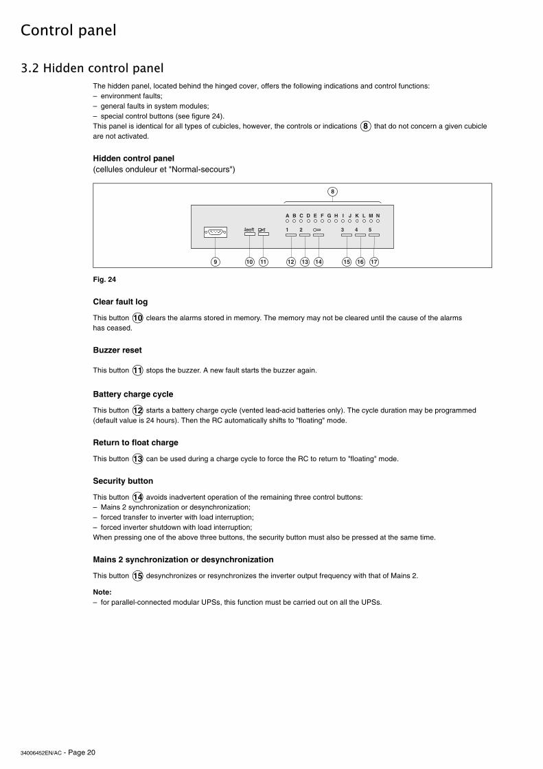
The hidden panel, located behind the hinged cover, offers the following indications and control functions:– environment faults;– general faults in system modules;– special control buttons (see figure 24).This panel is identical for all types of cubicles, however, the controls or indications that do not concern a given cubicle are not activated.
Fig. 24
This button clears the alarms stored in memory. The memory may not be cleared until the cause of the alarms has ceased.
This button stops the buzzer. A new fault starts the buzzer again.
This button starts a battery charge cycle (vented lead-acid batteries only). The cycle duration may be programmed (default value is 24 hours). Then the RC automatically shifts to "floating" mode.
This button can be used during a charge cycle to force the RC to return to "floating" mode.
This button avoids inadvertent operation of the remaining three control buttons:– Mains 2 synchronization or desynchronization;– forced transfer to inverter with load interruption;– forced inverter shutdown with load interruption;When pressing one of the above three buttons, the security button must also be pressed at the same time.
This button desynchronizes or resynchronizes the inverter output frequency with that of Mains 2.
Note: – for parallel-connected modular UPSs, this function must be carried out on all the UPSs.
8
./012 3#4567��
� % � ���$��
* ( � % � � + &
)
10
11
12
13
14
15
34006452EN/AC - Page 21
Control panel
Forced transfer to inverter with load interruption
Forced inverter shutdown with load interruption
Light A - emergency shutdown
Light B - rectifier-charger on
Light C - rectifier-charger fault
Light D - Mains 1 outside tolerances
Light E - battery room ventilation fault and/or harmonics filter temperature outside tolerances
Light F - battery temperature outside tolerances
Light G - battery charging
This button transfers the load to the inverter. If the transfer conditions (Mains 2 characteristics outside tolerances) are not correct, the transfer will result in a 0.8 second interruption in the supply of power to the load.
Note: – for parallel-connected modular UPSs, forced transfer of the load will not take place if the number of operating UPSs required by the load is greater than one;– for parallel UPSs with centralised SSC, this function is available only on the SSC.
This button :– transfers the load to Mains 2;– shuts down the inverter.It may be used if the transfer conditions (Mains 2 characteristics outside tolerances) are not correct, in which case the "inverter off" button on the visible control panel produces no effect;– is disabled on the SSC.
This red light signals that the remote "emergency shutdown" button was pressed (external information received and stored in memory).
This green light indicates that the rectifier-charger is on.
This red light is an alarm stored in memory signaling a rectifier-charger fault. It can signify one or several of the following faults:– input switch Q1 open;– RC input protection fuse (FU1-2-3) blown;– RC internal over-temperature;– battery charge over-current;– battery over-voltage;– RC electronic control board faulty, not calibrated or not personalized;– power supply board fault.
This yellow light signals that the Mains 1 voltage and/or frequency characteristics are outside tolerances.
This yellow light is an alarm stored in memory signaling a battery room ventilation fault (external information that must be supplied from the room).If the installation includes a harmonics filter, this light will also signal an overtemperature of the filter’s inductor (information supplied).
This yellow light signals that the battery temperature is outside tolerances (external information supplied by special board ("Temperature Monitor" option).
This yellow light signals that the battery is being recharged (vented batteries only). This light is deactivated in systems with sealed lead-acid batteries.
16
17
7
34006452EN/AC - Page 22
Control panel
Light H - inverter fault
Light I - battery discharged
Light J - inverter desynchronized with Mains 2
Light K - transfer to inverter function fault
Light L - overload
Light M - Mains 2 outside tolerances
Light N - maintenance position
Test connector
This red light is an alarm stored in memory signaling an inverter fault. It can signify one or several of the following faults:– inverter shutdown due to inverter output voltage outside tolerances;– inverter output protection fuse (FU5-6-7) blown;– inverter stack subassembly protection fuse blown (parallel systems);– inverter leg fault;– inverter output transformer over-temperature;– inverter leg over-temperature;– phase or output voltage fault (parallel systems only);– internal clock fault;– inverter control board faulty, not calibrated or not personalized;– power supply board fault.
This yellow light signals that the battery has reached its minimum voltage level, resulting in inverter shutdown.
This light signals that the inverter output frequency has been voluntarily desynchronized with that of Mains 2.
This red light is an alarm stored in memory signaling a fault in the systems for load transfer from Mains 2 to the inverter. It can signify one or several of the following faults:– inverter output switch K3N fault;– parallel-connection relay fault (parallel systems only);– static switch internal over-temperature;– static switch ventilation fault;– static switch power supply fault;– transfer function control board fault;– inverter control board not calibrated or not personalized;– power supply board fault.
This yellow light is an alarm signaling one or several of the following faults:– inverter stack current more than 5 % above rated current;– inverter output current more than 5 % above rated current;– Mains 2 line current more than 5 % above rated current;– inverter shutdown due to current limiting of output current.
This yellow light signals that the Mains 2 voltage or frequency characteristics are outside tolerances.
This yellow light signals that devices QF1, Q4S, Q5N and Q3BP are set to the maintenance configuration. The UPS system is not available for load protection.
This 9-pin connector is reserved for after-sales support technicians. It is used for connection to a microcomputer for:– system calibration;– personalization;– computer-aided diagnostics.
34006452EN/AC - Page 23
4. Start-up
4.1 System start-up
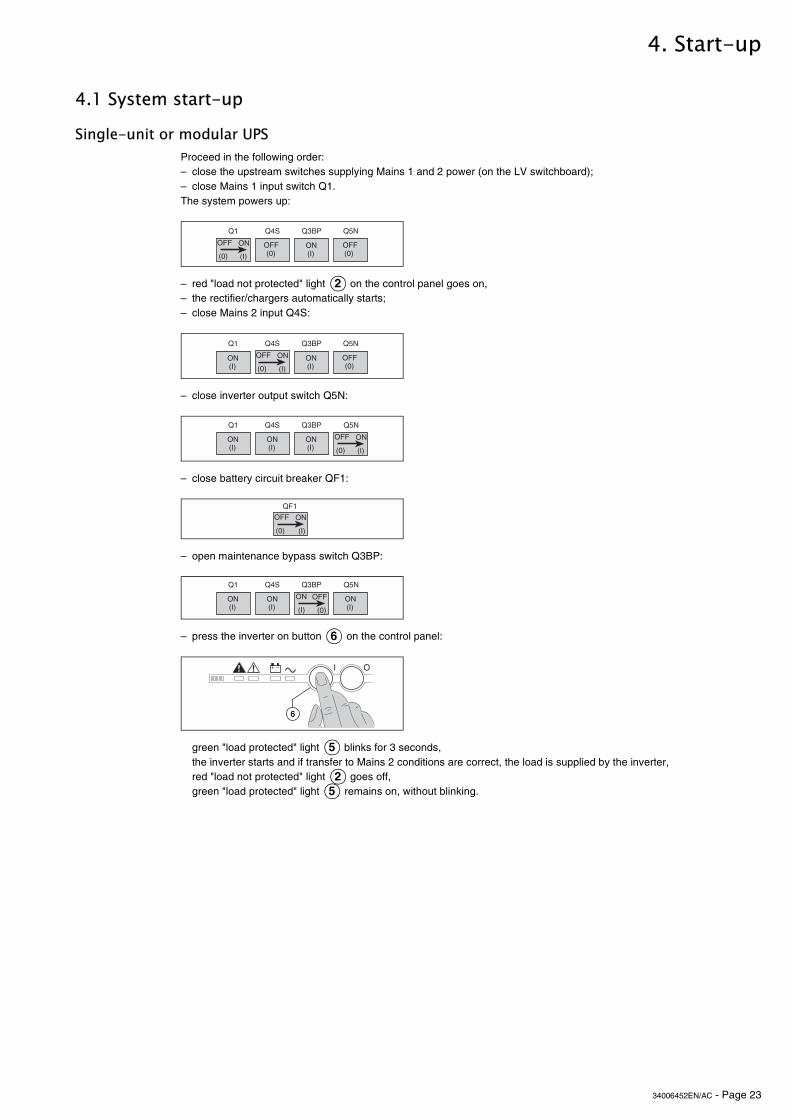
Single-unit or modular UPS Proceed in the following order:– close the upstream switches supplying Mains 1 and 2 power (on the LV switchboard);– close Mains 1 input switch Q1.The system powers up:
– red "load not protected" light on the control panel goes on,– the rectifier/chargers automatically starts;– close Mains 2 input Q4S:
– close inverter output switch Q5N:
– close battery circuit breaker QF1:
– open maintenance bypass switch Q3BP:
– press the inverter on button on the control panel:
green "load protected" light blinks for 3 seconds,the inverter starts and if transfer to Mains 2 conditions are correct, the load is supplied by the inverter,red "load not protected" light goes off,green "load protected" light remains on, without blinking.
�� �)# ��� �!"
-%% -"
0/1 0*1
-%%0/1
-"0*1
-%%0/1
2
�� �)# ��� �!"
-%% -"
0/1 0*1-"0*1
-"0*1
-%%0/1
�� �)# ��� �!"
-%% -"
0/1 0*1
-"0*1
-"0*1
-"0*1
�%�-%% -"
0/1 0*1
�� �)# ��� �!"
-" -%%
0*1 0/1
-"0*1
-"0*1
-"0*1
6
*+ ,�� -
+
5
25
34006452EN/AC - Page 24
Start-up
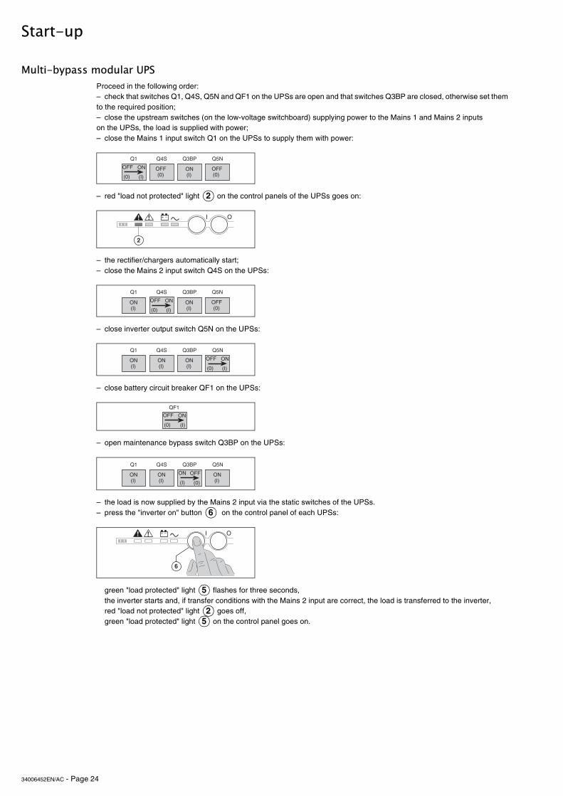
Multi-bypass modular UPS Proceed in the following order:– check that switches Q1, Q4S, Q5N and QF1 on the UPSs are open and that switches Q3BP are closed, otherwise set them to the required position;– close the upstream switches (on the low-voltage switchboard) supplying power to the Mains 1 and Mains 2 inputs on the UPSs, the load is supplied with power;– close the Mains 1 input switch Q1 on the UPSs to supply them with power:
– red "load not protected" light on the control panels of the UPSs goes on:
– the rectifier/chargers automatically start;– close the Mains 2 input switch Q4S on the UPSs:
– close inverter output switch Q5N on the UPSs:
– close battery circuit breaker QF1 on the UPSs:
– open maintenance bypass switch Q3BP on the UPSs:
– the load is now supplied by the Mains 2 input via the static switches of the UPSs.– press the "inverter on" button on the control panel of each UPSs:
green "load protected" light flashes for three seconds,the inverter starts and, if transfer conditions with the Mains 2 input are correct, the load is transferred to the inverter,red "load not protected" light goes off,green "load protected" light on the control panel goes on.
�� �)# ��� �!"
-%% -"
0/1 0*1
-%%0/1
-"0*1
-%%0/1
2
*+ ,�� -
�
�� �)# ��� �!"
-%% -"
0/1 0*1-"0*1
-"0*1
-%%0/1
�� �)# ��� �!"
-%% -"
0/1 0*1
-"0*1
-"0*1
-"0*1
�%�-%% -"
0/1 0*1
�� �)# ��� �!"
-" -%%
0*1 0/1
-"0*1
-"0*1
-"0*1
6
*+ ,�� -
+
5
25

34006452EN/AC - Page 25
Start-up
Modular UPS with external maintenance bypass Proceed in the following order:– check that all lines supplying the load are off or that the load is disconnected;– in the maintenance bypass cubicle, open output switch Q5N, then close bypass switch Q3BP;– close the upstream switch (on the low-voltage switchboard) supplying power to the Mains 1 inputs on the UPSs;– close the Mains 1 input switch Q1 on the UPSs to supply them with power:
– the rectifier/chargers automatically start;– red "load not protected" light on the control panels of the UPSs goes on:
– close battery circuit breaker QF1 on the UPSs:
– close the upstream switches (on the low-voltage switchboard) supplying power to the Mains 2 inputs on the UPSs, then close the Mains 2 input switch Q4S on the UPSs:
�� �!"
�%�
���
�)#
�� �!"
�%�
���
�)#
#���$��89�
����
������
��������
�������
�������������� ��
�������������
�������
#���$��89
������
��������
�������
�������������� ��
�������������
�������
�� �)# �!"
-%% -"
0/1 0*1
-%%0/1
-%%0/1
2
*+ ,�� -
�
�%�-%% -"
0/1 0*1
�� �)# �!"
-%% -"
0/1 0*1-"0*1
-%%0/1
34006452EN/AC - Page 26
Start-up
Frequency converters
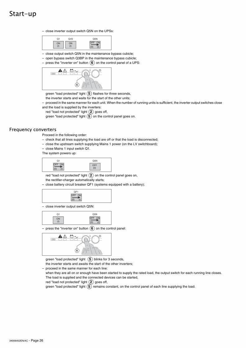
– close inverter output switch Q5N on the UPSs:
– close output switch Q5N in the maintenance bypass cubicle;– open bypass switch Q3BP in the maintenance bypass cubicle;– press the "inverter on" button on the control panel of a UPS:
green "load protected" light flashes for three seconds,the inverter starts and waits for the start of the other units;
– proceed in the same manner for each unit. When the number of running units is sufficient, the inverter output switches close and the load is supplied by the inverters:
red "load not protected" light goes off,green "load protected" light on the control panel goes on.
Proceed in the following order:– check that all lines supplying the load are off or that the load is disconnected;– close the upstream switch supplying Mains 1 power (on the LV switchboard);– close Mains 1 input switch Q1. The system powers up:
red "load not protected" light on the control panel goes on,the rectifier-charger automatically starts;
– close battery circuit breaker QF1 (systems equipped with a battery);
– close inverter output switch Q5N:
– press the "inverter on" button on the control panel:
green "load protected" light blinks for 3 seconds,the inverter starts and awaits the start of the other inverters;
– proceed in the same manner for each line:when they are all on or enough have been started to supply the rated load, the output switch for each running line closes. The load is supplied and the connected devices can be started,red "load not protected" light goes off,green "load protected" light remains constant, on the control panel of each line supplying the load.
�� �)# �!"
-%% -"
0/1 0*1
-"0*1
-"0*1
6
*+ ,�� -
+
5
25
�� �!"
-%% -"
0/1 0*1
-%%0/1
2
�%�-%% -"
0/1 0*1
�� �!"
-%% -"
0/1 0*1-"0*1
6
*+ ,�� -
+
5
25
34006452EN/AC - Page 27
Start-up
Parallel UPS systems with a Static Switch Cubicle
4.2 Start-up of a unit
Start-up of a rectifier/charger
Start-up of an inverter
Single-unit or modular UPS system:
Frequency converter or multi-bypass UPS:
Modular UPS with external maintenance bypass or parallel UPS with SSC:
Frequency converter without a battery:
Proceed in the following order:– check that all lines supplying the load are off or that the load is disconnected;– close the upstream switches supplying Mains 1 and 2 power (on the LV switchboard);– close fuse switch Q2 in the Static Switch Cubicle (see figure 19);– close Mains 2 input switch Q4S in the Static Switch Cubicle;– close switch Q5N in the Static Switch Cubicle;– open maintenance bypass switch Q3BP in the Static Switch Cubicle;– close fuse switch Q1 in the Static Switch Cubicle;– close input switch Q1 on an UPS line. The line powers up;– red "load not protected" light on the line control panel goes on,– the RC automatically starts;– close the line battery circuit breaker QF1;– close inverter output switch Q5N for the line;– press the "inverter on" button on the line control panel;– green "load protected" light blinks for 3 seconds,– the inverter starts and awaits the start of the other inverters;– proceed in the same manner for each line;– when they are all on or enough have been started to supply the rated load power, the output switch for each running line closes and the load is supplied with power;– red "load not protected" light goes off,– green "load protected" light remains on, without blinking, on the control panel of each line supplying the load.
– it is recommended not to stop the rectifier/charger because the battery will no longer be charged. Rectifier/charger start-up is automatic when Mains 1 input switch Q1 is closed;– red "load not protected" light on the control panel goes on;– close battery circuit breaker QF1.
When the rectifier/charger is on:– press the "inverter on" button on the control panel;
– green "load protected" light blinks for 3 seconds;
– the inverter starts and if the transfer to Mains 2 conditions are correct, the load is supplied by the inverter;– red "load not protected" light goes off,
– green "load protected" light becomes constant.
– the inverter starts and awaits the start of the other inverters;– when they are all on or enough have been started to supply the rated load power, the output switch for each running line closes and the load is supplied with power;– red "load not protected" light goes off,
– green "load protected" light becomes constant, on the control panel of each line supplying the load.
– the inverter starts and awaits the start of the other inverters;– when they are all on or enough have been started to supply the rated load power, the output switch for each running line closes and the load is supplied with power;– red "load not protected" light goes off,
– green "load protected" light remains on, without blinking, on the control panel of each line supplying the load and on the control panel of the Static Switch Cubicle.
– Start-up of the rectifier/charger automatically leads to start-up of the inverter.
2
65
25
2
65
25
25
25
34006452EN/AC - Page 28
5. Shutdown
5.1 Shutdown of a unit
Shutdown of an inverter
Single-unit UPS
Multi-bypass modular UPS:
Modular UPS with external maintenance bypass:
Frequency converter:
Parallel UPS with SSC:
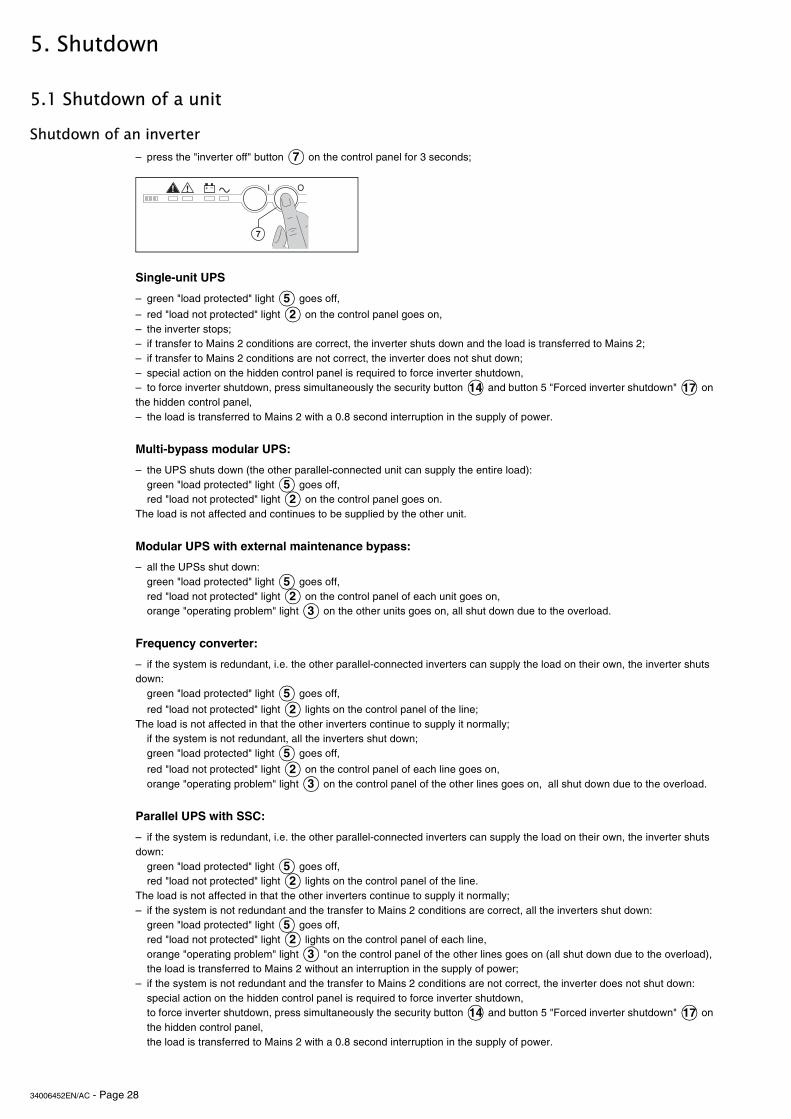
– press the "inverter off" button on the control panel for 3 seconds;
– green "load protected" light goes off,
– red "load not protected" light on the control panel goes on,– the inverter stops;– if transfer to Mains 2 conditions are correct, the inverter shuts down and the load is transferred to Mains 2;– if transfer to Mains 2 conditions are not correct, the inverter does not shut down;– special action on the hidden control panel is required to force inverter shutdown,– to force inverter shutdown, press simultaneously the security button and button 5 "Forced inverter shutdown" on the hidden control panel,– the load is transferred to Mains 2 with a 0.8 second interruption in the supply of power.
– the UPS shuts down (the other parallel-connected unit can supply the entire load):green "load protected" light goes off,red "load not protected" light on the control panel goes on.
The load is not affected and continues to be supplied by the other unit.
– all the UPSs shut down:green "load protected" light goes off,red "load not protected" light on the control panel of each unit goes on,orange "operating problem" light on the other units goes on, all shut down due to the overload.
– if the system is redundant, i.e. the other parallel-connected inverters can supply the load on their own, the inverter shuts down:
green "load protected" light goes off,
red "load not protected" light lights on the control panel of the line;The load is not affected in that the other inverters continue to supply it normally;
if the system is not redundant, all the inverters shut down;green "load protected" light goes off,
red "load not protected" light on the control panel of each line goes on,orange "operating problem" light on the control panel of the other lines goes on, all shut down due to the overload.
– if the system is redundant, i.e. the other parallel-connected inverters can supply the load on their own, the inverter shuts down:
green "load protected" light goes off,red "load not protected" light lights on the control panel of the line.
The load is not affected in that the other inverters continue to supply it normally;– if the system is not redundant and the transfer to Mains 2 conditions are correct, all the inverters shut down:
green "load protected" light goes off,red "load not protected" light lights on the control panel of each line,orange "operating problem" light "on the control panel of the other lines goes on (all shut down due to the overload),the load is transferred to Mains 2 without an interruption in the supply of power;
– if the system is not redundant and the transfer to Mains 2 conditions are not correct, the inverter does not shut down:special action on the hidden control panel is required to force inverter shutdown,to force inverter shutdown, press simultaneously the security button and button 5 "Forced inverter shutdown" on the hidden control panel,the load is transferred to Mains 2 with a 0.8 second interruption in the supply of power.
7
*+ ,�� -
&
52
14 17
52
52
3
52
52
3
52
52
3
14 17
34006452EN/AC - Page 29
Shutdown
Shutdown of an rectifier/charger
5.2 System shutdown
Single-unit or single modular UPS
Except in frequency converters without a battery, it is recommended not to stop the rectifier/charger because the battery will no longer be charged. Except in the case of a test of the inverter on battery power, the rectifier/charger should be shutdown after the inverter to avoid unnecessary battery discharge.Proceed in the following order:– open battery circuit breaker QF1;– open Mains 1 input switch Q1;– the rectifier/charger shuts down,– all control panel lights go off because the device is powered down.
Note:In a frequency converter without a battery, rectifier/charger shutdown automatically results in inverter shutdown.
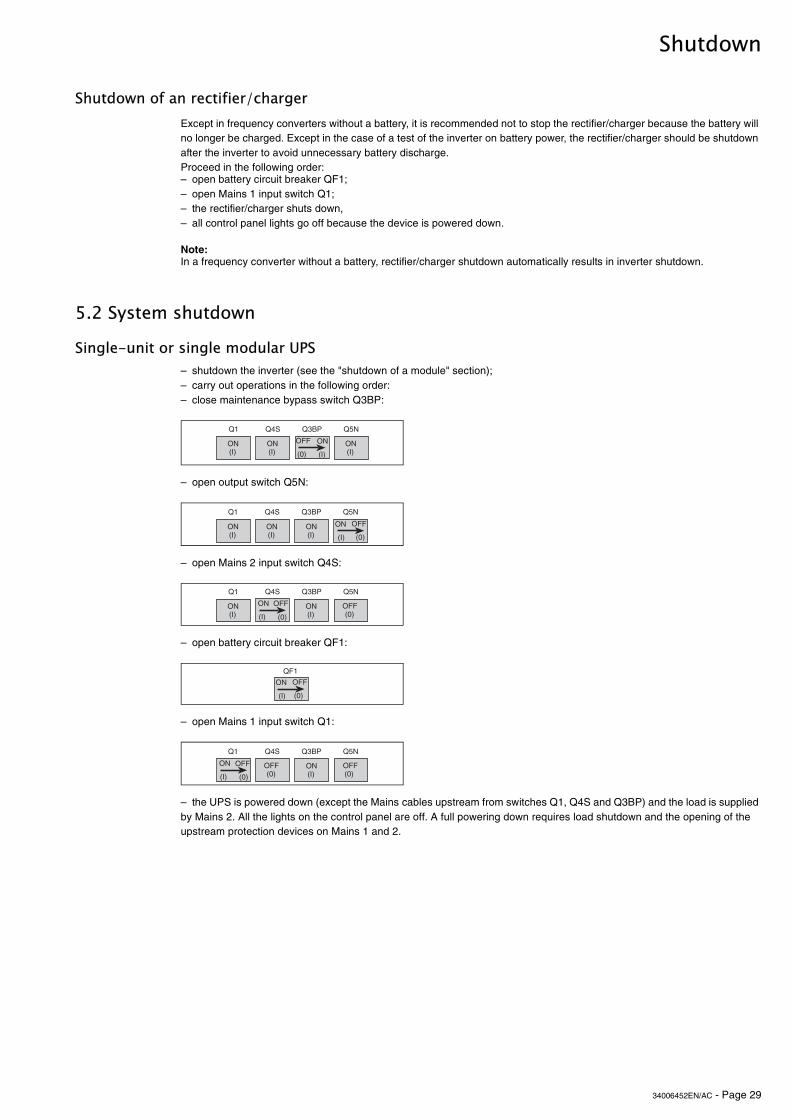
– shutdown the inverter (see the "shutdown of a module" section);– carry out operations in the following order:– close maintenance bypass switch Q3BP:
– open output switch Q5N:
– open Mains 2 input switch Q4S:
– open battery circuit breaker QF1:
– open Mains 1 input switch Q1:
– the UPS is powered down (except the Mains cables upstream from switches Q1, Q4S and Q3BP) and the load is supplied by Mains 2. All the lights on the control panel are off. A full powering down requires load shutdown and the opening of the upstream protection devices on Mains 1 and 2.
�� �)# ��� �!"
-%% -"
0/1 0*1-"0*1
-"0*1
-"0*1
�� �)# ��� �!"
-%%-"
0/10*1-"0*1
-"0*1
-"0*1
�� �)# ��� �!"
-" -%%
0*1 0/1-"0*1
-"0*1
-%%0/1
�%�-%%-"
0/10*1
�� �)# ��� �!"
-" -%%
0*1 0/1
-%%0/1
-"0*1
-%%0/1
34006452EN/AC - Page 30
Shutdown
Modular UPS with external maintenance bypass
Frequency converters (no Mains 2)
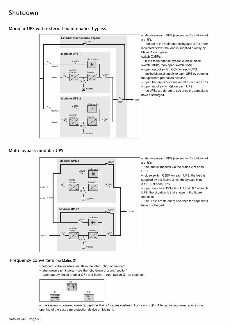
– shutdown each UPS (see section "shutdown of a unit");– transfer to the maintenance bypass in the order indicated below (the load is supplied directly by Mains 2 via bypass switch Q3BP):– in the maintenance bypass cubicle, close switch Q3BP, then open switch Q5N;– open output switch Q5N for each UPS;– cut the Mains 2 supply to each UPS by opening the upstream protection devices;– open battery circuit breaker QF1 on each UPS;– open input switch Q1 on each UPS;– the UPSs are de-energised once the capacitors have discharged.
Multi-bypass modular UPS – shutdown each UPS (see section "shutdown of a unit");– the load is supplied via the Mains 2 of each UPS;– close switch Q3BP on each UPS, the load is supplied by the Mains 2, via the bypass lines (Q3BP) of each UPS;– open switches Q5N, Q4S, Q1 and QF1 on each UPS, the situation is that shown in the figure opposite;– the UPSs are de-energised once the capacitors have discharged.
Shutdown of the inverters results in the interruption of the load;– shut down each inverter (see the "shutdown of a unit" section);– open battery circuit breaker QF1 and Mains 1 input switch Q1 on each unit;
– the system is powered down (except the Mains 1 cables upstream from switch Q1). A full powering down requires the opening of the upstream protection device on Mains 1.
�� �!"
�%�
���
�)#
�� �!"
�%�
�)#
/�������89�
/�������89
�!"
5$���������������"��� ���
����
������
��������
�������
�������������� ��
�������������
�������
������
��������
�������
�������������� ��
�������������
�������
�� �!"
�%�
���
�)#
�� �!"
�%�
���
�)#
/�������89�
/�������89
����
������
��������
�������
�������������� ��
�������������
������
��������
�������
�������������� ��
�������������
�������
�� �!"
-" -%%
0*1 0/1
-"0*1
�%�-%%-"
0/10*1

34006452EN/AC - Page 31
Shutdown
Parallel UPSs with SSC (with Mains 2)
5.3 Buzzer reset
– shut down each inverter (see the "shutdown of a unit" section);– carry out the maintenance bypass operation in the Static Switch Cubicle (the load will be directly supplied by Mains 2 via maintenance bypass switch Q3BP);– close switch Q3BP and open switches Q5N and Q4S in the "static switch" cubicle;– open fuse switches Q1 and Q2 in the Static Switch Cubicle;– open battery circuit breaker QF1 in each UPS (except for frequency converters without a battery);– open input switch Q1 for each UPS;– the UPSs are powered down (except the Mains cables upstream from switches Q1, Q4S and Q3BP) and the load is supplied by Mains 2. All the lights on the control panel are off. A full powering down requires load shutdown and the opening of the upstream protection devices on Mains 1 and 2.
– first determine the cause of the alarm;– press the "buzzer reset" button on the hidden control panel on the concerned cubicle.The buzzer stops, but a new alarm will set it off again.
11
� � 7 6 5 4 # 3 2 1 0 / .
� % � �

34006452EN/AC - Page 32
6. Alarms
6.1 Maintenance bypass
The autodiagnostic system considers any system status other than normal as a problem.Prior to any other action, note any lights (A to N) on the hidden control panel that may be on.Also note any messages on the screen.Certain problems may result in the control panel not functioning.In this case, it is strongly recommended to call the after-sales support department.– if the load is still correctly supplied with power, it has probably been transferred to Mains 2 (static switch) and is therefore no longer protected;– if the load is no longer supplied with power, transfer it manually to the maintenance bypass (see section below).
This operation is possible only if the system includes a Mains 2. It results in the load being directly supplied by Mains 2 via maintenance bypass switch Q3BP, thus ensuring a higher level of security in the event of a malfunction.Important:Prior to beginning the bypass operation, shut down all system inverters (press the "inverter off" button on each UPS control panel). If an inverter remains operating and the Mains 2 transfer conditions are not correct, the load will suffer a 0.8 second interruption.Switching procedures are explained on a drawing next to each switch. It is imperative that the operation proceed in the following order:– shut down any inverters that may still be running;
– 1 : close maintenance bypass switch Q3BP;– 2 : open inverter output switch Q5N;– 3 : open Mains 2 input switch Q4S:
Note:– in systems with a Static Switch Cubicle, the above operation is carried out in the Static Switch Cubicle;– the operation with the three switches is carried out in reverse order (3, 2, 1) to return to normal status;– in an installation comprising modular UPSs with an external maintenance bypass, the operation is carried out in the external maintenance bypass. The cubicle is not equipped with a Q4S switch and it is therefore necessary to open the protection devices upstream on the maintenance-bypass line.
7
*+ ,�� -
&
�� �)# ��� �!"
�
�
�
�� ���
-%% -"
0/1 0*1-"0*1
-"0*1
-"0*1
-%%-"
0/10*1-"0*1
-"0*1
-"0*1
-" -%%
0*1 0/1-"0*1
-"0*1
-%%0/1
34006452EN/AC - Page 33
7. Environment information
7.1 Standard information Media Contacts 9
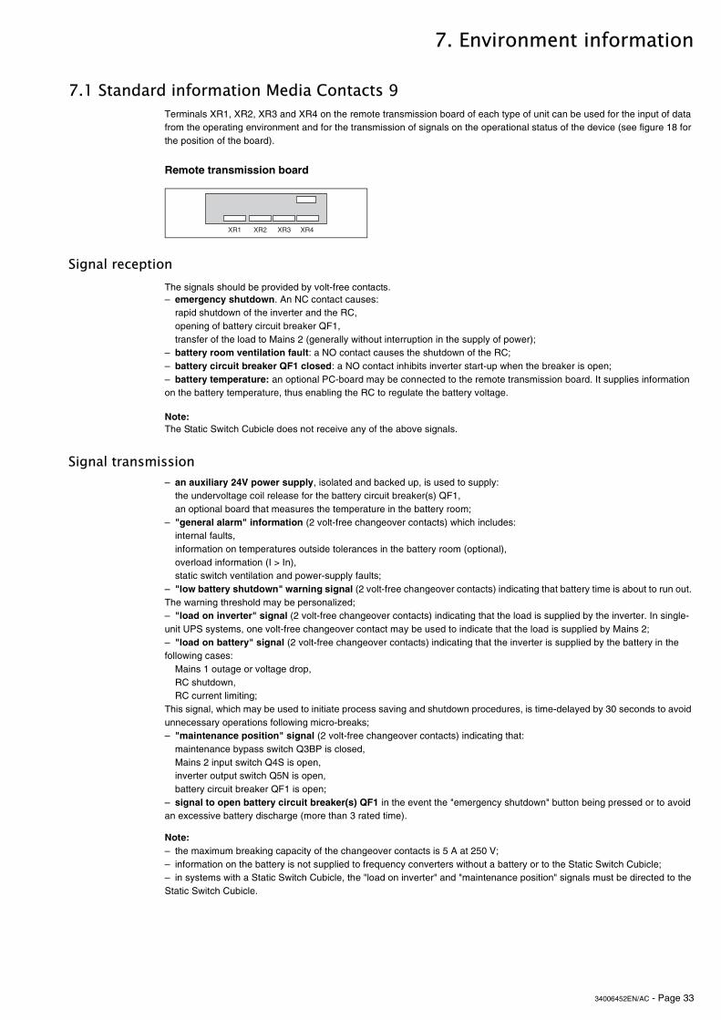
Remote transmission board
Signal reception
Signal transmission
Terminals XR1, XR2, XR3 and XR4 on the remote transmission board of each type of unit can be used for the input of data from the operating environment and for the transmission of signals on the operational status of the device (see figure 18 for the position of the board).
The signals should be provided by volt-free contacts.– emergency shutdown. An NC contact causes:
rapid shutdown of the inverter and the RC,opening of battery circuit breaker QF1,transfer of the load to Mains 2 (generally without interruption in the supply of power);
– battery room ventilation fault: a NO contact causes the shutdown of the RC;– battery circuit breaker QF1 closed: a NO contact inhibits inverter start-up when the breaker is open;– battery temperature: an optional PC-board may be connected to the remote transmission board. It supplies information on the battery temperature, thus enabling the RC to regulate the battery voltage.
Note:The Static Switch Cubicle does not receive any of the above signals.
– an auxiliary 24V power supply, isolated and backed up, is used to supply:the undervoltage coil release for the battery circuit breaker(s) QF1,an optional board that measures the temperature in the battery room;
– "general alarm" information (2 volt-free changeover contacts) which includes:internal faults,information on temperatures outside tolerances in the battery room (optional),overload information (I > In),static switch ventilation and power-supply faults;
– "low battery shutdown" warning signal (2 volt-free changeover contacts) indicating that battery time is about to run out. The warning threshold may be personalized;– "load on inverter" signal (2 volt-free changeover contacts) indicating that the load is supplied by the inverter. In single-unit UPS systems, one volt-free changeover contact may be used to indicate that the load is supplied by Mains 2;– "load on battery" signal (2 volt-free changeover contacts) indicating that the inverter is supplied by the battery in the following cases:
Mains 1 outage or voltage drop,RC shutdown,RC current limiting;
This signal, which may be used to initiate process saving and shutdown procedures, is time-delayed by 30 seconds to avoid unnecessary operations following micro-breaks;– "maintenance position" signal (2 volt-free changeover contacts) indicating that:
maintenance bypass switch Q3BP is closed,Mains 2 input switch Q4S is open,inverter output switch Q5N is open,battery circuit breaker QF1 is open;
– signal to open battery circuit breaker(s) QF1 in the event the "emergency shutdown" button being pressed or to avoid an excessive battery discharge (more than 3 rated time).
Note:– the maximum breaking capacity of the changeover contacts is 5 A at 250 V;– information on the battery is not supplied to frequency converters without a battery or to the Static Switch Cubicle;– in systems with a Static Switch Cubicle, the "load on inverter" and "maintenance position" signals must be directed to the Static Switch Cubicle.
9:� 9:� 9:� 9:)
34006452EN/AC - Page 34
Environment information
7.2 "LED" signalling box (optional)
7.3 Additional information "Media Contacts 15"
Additional remote transmission board
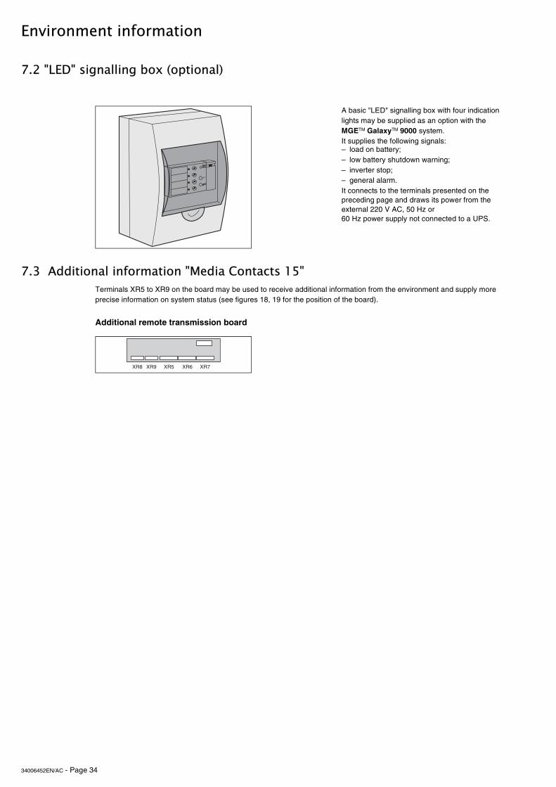
A basic "LED" signalling box with four indication lights may be supplied as an option with the MGETM GalaxyTM 9000 system. It supplies the following signals:– load on battery;– low battery shutdown warning;– inverter stop;– general alarm.It connects to the terminals presented on the preceding page and draws its power from the external 220 V AC, 50 Hz or 60 Hz power supply not connected to a UPS.
Terminals XR5 to XR9 on the board may be used to receive additional information from the environment and supply more precise information on system status (see figures 18, 19 for the position of the board).
����
9:! 9:' 9:(9:;9:<

34006452EN/AC - Page 35
Environment information
Signal reception
Signal transmission
The signals should be provided by volt-free contacts.– "desynchronization with Mains 2" signal inhibits the inverter from synchronizing its output frequency with that of Mains 2. The inverter supplies a stable frequency and the load may no longer be correctly transferred from the inverter to Mains 2. In the event of a malfunction or an overload, the transfer will take place with a 0.8 second interruption in the supply of power to the load;– "gradual rectifier/charger shutdown" signal makes the rectifier/charger shut down progressively to avoid excessive step load variations in the event of a low output engine generator set replacing Mains 1;– "generator current limiting" signal makes the rectifier/charger current limit the power drawn when a low output engine generator set has replaced Mains 1. The additional power required for the inverter is supplied by the battery;– "battery charge current limiting" signal reduces the battery charge current (programmable parameter) in the event a low output engine generator set has replaced Mains 1;– "transfer to Mains 2 disabled" signal blocks transfer of the load from the inverter to Mains 2. In the event the inverter shuts down (overload, etc.), the load is no longer supplied (for modular UPSs, this information is disabled and transferred to an auxiliary output);– "transfer to Mains 2 with interruption disabled" signal blocks transfer of the load from the inverter to Mains 2 if it would result in an interruption in the supply of power to the load. Only no-break transfers are allowed, i.e. transfer to Mains 2 conditions must be correct or the transfer is disabled (for modular UPSs, this information is disabled and transferred to an auxiliary output);– "auxiliary" signal can be used to provoke (depending on personalization):
a forced shutdown of the inverter (regardless of the status of Mains 2),a protected inverter shutdown (transfer of the load to Mains 2 without interruption only if it is within tolerances),modification of the inverter output frequency (50 Hz or 60 Hz);
– "remote inverter on" signal can be used to remotely start the inverter;– "remote inverter off" signal can be used to remotely shut down the inverter.
Note:In a system with a Static Switch Cubicle, the following signals must be directed to the Static Switch Cubicle:– desynchronization with Mains 2,– transfer to Mains 2 disabled,– transfer to Mains 2 with interruption disabled.
These signals are each transmitted by two volt-free changeover contacts with a maximum breaking capacity of 5 A 250 V.– "overload" signal indicates that an overload has taken place (Pload > Pnominal in kVA);– "rectifier/charger function fault" signal indicates that:– a fault has taken place in the rectifier/charger module,– Mains 1 input switch Q1 is open;– "inverter function fault" signal indicates that a fault has taken place in the inverter module;– "transfer to inverter fault" signal indicates that the load transfer conditions from Mains 2 to the inverter are incorrect;– "transfer to Mains 2 fault" signal indicates that the transfer to Mains 2 conditions (voltage, frequency or phase) are incorrect and a forced transfer will result in a 0.8 second interruption in the supply of power to the load;– "rectifier/charger on" signal indicates the status of the module.
Note:A Static Switch Cubicle receives only the following signals:– overload,– transfer to inverter fault,– transfer to Mains 2 fault.
34006452EN/AC - Page 36
8. Maintenance
8.1 Maintenance configuration
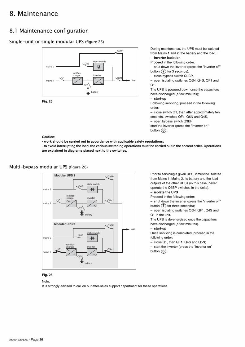
Single-unit or single modular UPS (figure 25)
Caution:- work should be carried out in accordance with applicable safety regulations;- to avoid interrupting the load, the various switching operations must be carried out in the correct order. Operations are explained in diagrams placed next to the switches.
Multi-bypass modular UPS (figure 26)
Note:It is strongly advised to call on our after-sales support department for these operations.
During maintenance, the UPS must be isolated from Mains 1 and 2, the battery and the load.– inverter isolationProceed in the following order:– shut down the inverter (press the "inverter off" button for 3 seconds),– close bypass switch Q3BP,– open isolating switches Q5N, Q4S, QF1 and Q1.The UPS is powered down once the capacitors have discharged (a few minutes);– start-upFollowing servicing, proceed in the following order:– close switch Q1, then after approximately ten seconds, switches QF1, Q5N and Q4S,– open bypass switch Q3BP,start the inverter (press the "inverter on" button ).
Fig. 25
Prior to servicing a given UPS, it must be isolated from Mains 1, Mains 2, its battery and the load outputs of the other UPSs (in this case, never operate the Q3BP switches in the units).– isolate the UPSProceed in the following order:– shut down the inverter (press the "inverter off" button for three seconds);– open isolating switches Q5N, QF1, Q4S and Q1 in the unit.The UPS is de-energised once the capacitors have discharged (a few minutes).– start-upOnce servicing is completed, proceed in the following order:– close Q1, then QF1, Q4S and Q5N;– start the inverter (press the “inverter on” button ).
Fig. 26
�� �!"
�%�
���
�)#
����
������
��������
�������
�������������� ��
�������������
�������
7
6
�� �!"
�%�
���
�)#
�� �!"
�%�
���
�)#
/�������89�
/�������89
����
������
��������
�������
�������������� ��
�������������
������
��������
�������
�������������� ��
�������������
�������
�������
7
6
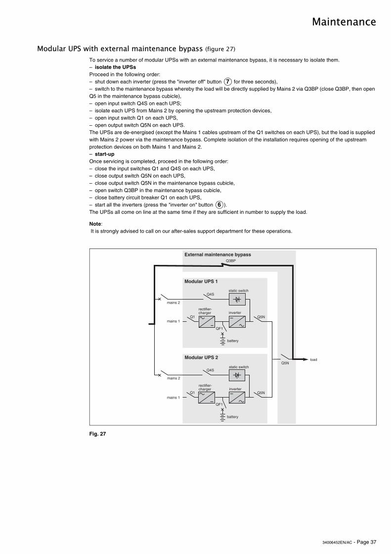
34006452EN/AC - Page 37
Maintenance
Modular UPS with external maintenance bypass (figure 27)
To service a number of modular UPSs with an external maintenance bypass, it is necessary to isolate them.– isolate the UPSsProceed in the following order:– shut down each inverter (press the "inverter off" button for three seconds),– switch to the maintenance bypass whereby the load will be directly supplied by Mains 2 via Q3BP (close Q3BP, then open Q5 in the maintenance bypass cubicle),– open input switch Q4S on each UPS;– isolate each UPS from Mains 2 by opening the upstream protection devices,– open input switch Q1 on each UPS,– open output switch Q5N on each UPS.The UPSs are de-energised (except the Mains 1 cables upstream of the Q1 switches on each UPS), but the load is supplied with Mains 2 power via the maintenance bypass. Complete isolation of the installation requires opening of the upstream protection devices on both Mains 1 and Mains 2.– start-upOnce servicing is completed, proceed in the following order:– close the input switches Q1 and Q4S on each UPS,– close output switch Q5N on each UPS,– close output switch Q5N in the maintenance bypass cubicle,– open switch Q3BP in the maintenance bypass cubicle,– close battery circuit breaker Q1 on each UPS,– start all the inverters (press the "inverter on" button ).The UPSs all come on line at the same time if they are sufficient in number to supply the load.
Note: It is strongly advised to call on our after-sales support department for these operations.
Fig. 27
7
6
�� �!"
�%�
���
�)#
�� �!"
�%�
�)#
/�������89�
/�������89
�!"
5$���������������"��� ���
����
������
��������
�������
�������������� ��
�������������
�������
������
��������
�������
�������������� ��
�������������
�������

34006452EN/AC - Page 38
Maintenance
Frequency converter or parallel UPS with SSC (figure 28)
Note:We recommend that you call on the after-sales support department to carry out these operations.
Static Switch Cubicle (figure 29)
Note:We recommend that you call on the after-sales support department to carry out these operations.
During maintenance, the concerned UPS or converter must be isolated from Mains 1, its battery and the output circuits of the other units.– inverter isolationProceed in the following order:– shut down the inverter (press the "inverter off" button for 3 seconds),– open isolating switches Q5N, QF1 and Q1 for that line.The unit is powered down once the capacitors have discharged (a few minutes).In redundant systems with at least one redundant UPS, the other UPSs (or converters) ensure continuity of power to the load.In non-redundant systems with a Mains 2, the load is supplied by the Mains 2 and the Static Switch Cubicle.In non-redundant systems without a Mains 2, the entire system must be shut down.– start-upFollowing servicing, proceed in the following order:– close switch Q1, then switches QF1, Q5N and Q4S,
start the inverter (press the "inverter on" button ).
Fig. 28: frequency converter exemple
During maintenance, the Static Switch Cubicle must be isolated from Mains 2, the load and the parallel UPSs.– if work is required on the control electronics alone, open cubicle switch Q4S (but not Q5N) and cubicle fuse switches Q1 and Q2. The load can then remain supplied by the UPSs. After servicing, reclose fuse switches Q1, Q2 and switch Q4S.Caution:When the Static Switch Cubicle is powered down using the above procedure, only the control electronics are in fact powered down. The power circuits remain energized. Maintenance on the static switch power circuits requires shutdown of the UPSs and transfer of the load to the maintenance bypass line.– open switch Q5N, then the disconnector-fuses Q1 and Q2 in the SSC;– open switches Q5N, then switch Q4S on all the UPSs (figure 29).Caution:Even in the maintenance bypass configuration, the cubicle is only partially shut down and the supply of power to the load continues via switch Q3BP.
more extensive maintenance work on the Static Switch Cubicle requires the entire system to be shut down.
Fig. 29
������� ����
�������
�������
�%�
�%�
�%�
��
��
��
�!"
�!"
�!"
7
6
�������
����
�������
�������
�%�
�%�
��
��
�!"
�!"
�!"
���
�)#

34006452EN/AC - Page 39
Maintenance
8.2 Battery maintenance
8.3 Autodiagnostics
8.4 Visual check
8.5 Functional check
Consult the instructions supplied by the battery manufacturer. Below are a few general indications:– sealed lead-acid batteries. These batteries require no maintenance:
but check the terminals of each cell from time to time and clean if necessary;– vented lead-acid batteries:
check the electrolyte level regularly and add water if necessary,check the voltage of each cell to determine if it is necessary to equalize the battery,check the terminals of each cell and clean if necessary.
Caution:Battery maintenance is undertaken with the system powered up. Operations must be carried out in accordance with applicable safety regulations by qualified personnel using insulated tools, gloves and safety goggles.Batteries contain dangerous substances that will harm the environment if thrown away. If you change the batteries yourself, call on qualified organizations for battery disposal and recycling.
Note the indications supplied on the hidden control panel (lights A to N ). See the "control panel" section.In systems with one or several alphanumeric displays, check the list of alarms.If there is a true malfunction, note the indications and alarms and call the after-sales support department.
– after-sales support technicians will power down the system prior to any maintenance operations.Note:In redundant, parallel UPS systems and frequency converters, the check may be carried out successively on each UPS or converter without interrupting the load. In other configurations and for the Static Switch Cubicle, the load must be supplied via the maintenance bypass (see the "Alarm" section).– clean the system regularly, particularly the air inlet and outlet grills. Check that the air circulates freely in the cubicles. – Use a vacuum cleaner if necessary;– check that nothing hinders the ventilation at the top of the system;– check that all the fans operate correctly.
– check that lights J, K, M and N on the hidden control panel are not on to avoid an interruption in the supply of power to the load due to incorrect transfer conditions or a battery problem;– press the "inverter off" button and check that the buzzer and control panel lights function correctly (see the "main operating modes" section);– press the "inverter on" button and check again that the control panel lights function correctly;– run a transfer to battery test. With the inverter on, open input switch Q1.The orange "battery" light on the control panel should light. After two minutes on battery power, close input switch Q1. The rectifier/charger should automatically restart and the orange "battery" light on the control panel should go off;– in parallel systems, run these tests on each UPS or converter.
8� 8�
8

34006452EN/AC - Page 40
Maintenance
8.6 Training centresTo allow you to use APC by Schneider Electric products effectively and carry out basic maintenance, we offer a complete range of technical training courses in English and French.
Schneider Critical Power & Cooling Services 50 Hz training centres
Schneider Critical Power & Cooling Services 50-60 Hz training centre
France Training Centre140, Avenue Jean KuntzmannInnovallée38334 - St Ismier Cedex - FRANCE
United States Training Centre132 Fairgrounds RoadWest Kingston - RI02892U.S.A
Tél : +33 (0)4 76 18 34 14Fax : +33 (0)4 76 18 45 21
Tél : +1 877 800 4272
Singapore Training Centre10 Ang MO Kio Street 65, #03-06/10Techpoint BuildingSingapore 569059Singapore
Tél : +65 6389 6792
China Training CentreN° 999, Shen Fu RoadMin Hang DistrictShanghai 201108P.R. China
Tél : +86 21 3407 3365Fax: +86 21 3407 4526
http://powerlearning.apc.comCatalogue and registration available on line.
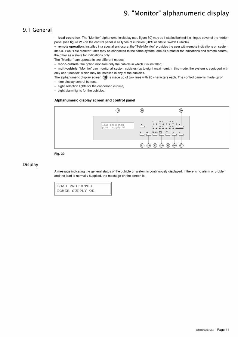
34006452EN/AC - Page 41
9. "Monitor" alphanumeric display
9.1 General
Alphanumeric display screen and control panel
Display
– local operation. The "Monitor" alphanumeric display (see figure 30) may be installed behind the hinged cover of the hidden panel (see figure 21) on the control panel in all types of cubicles (UPS or Static Switch Cubicle).– remote operation. Installed in a special enclosure, the "Tele Monitor" provides the user with remote indications on system status. Two "Tele Monitor" units may be connected to the same system, one as a master for indications and remote control, the other as a slave for indications only.The "Monitor" can operate in two different modes:– mono-cubicle: the option monitors only the cubicle in which it is installed;– multi-cubicle: "Monitor" can monitor all system cubicles (up to eight maximum). In this mode, the system is equipped with only one "Monitor" which may be installed in any of the cubicles.The alphanumeric display screen is made up of two lines with 20 characters each. The control panel is made up of:– nine display control buttons,– eight selection lights for the concerned cubicle,– eight alarm lights for the cubicles.
Fig. 30
A message indicating the general status of the cubicle or system is continuously displayed. If there is no alarm or problem and the load is normally supplied, the message on the screen is:
18
)&+��%�
�� �+ �&
*
���%���
+ , �:;3<�-
�()
=
����������������� �������
LOAD PROTECTED POWER SUPPLY OK

34006452EN/AC - Page 42
"Monitor" alphanumeric display
9.2 Control panel "Settings" button . This button can be used to select the display language, adjust screen contrast to local conditions and, for the "Tele Monitor" option, adjust the volume level of the buzzer."V" button . Provides access to voltage measurements:– Mains 1 phase-to-phase voltages;– Mains 2 phase-to-neutral and phase-to-phase voltages;– inverter output phase-to-neutral and phase-to-phase voltages;– load phase-to-neutral and phase-to-phase voltages."A" button . Provides access to current measurements:– currents on the Mains 1 and 2 lines and the load;– percent current drawn by the load;– percent load with regards to the rated value;– load current peak factor."W.Hz" button . Provides access to measurements:– Mains 1 and 2 and inverter frequency;– active and apparent power drawn by the load;– load power factor."Battery" button . Provides access to battery measurements:– battery voltage (or DC voltage for frequency converters without a battery);– battery current (charge or discharge);– battery temperature (optional);– remaining battery time."Alarms" button . Displays current or logged alarms and stops the buzzer for the "Tele Monitor" option. A blinking character ("!", "A" or "kW") at the end of the line indicates that the user must press the "alarms" "A" or "W.Hz" button respectively to display the remaining alarms or further information."I/O" button . Provides access to On/Off controls. This button is active only on remote, master "Tele Monitor" units."*" button . This button has a number of functions depending on the displayed messages (confirmation, positive response, etc.). Pressing this button followed immediately by the "V" button (less than one second) provides access to the display configuration function. In "Monitor" multi-cubicles mode, this button can also be used to display the type of cubicle concerned by the displayed message. The information disappears when the button is released. For example:
">" buttonThis button has a number of functions depending on the displayed messages (selection, negative response, etc.). In "Monitor" multi-cubicles mode, this button can also be used to select one of the eight cubicles that may be connected to the "Monitor" unit, in which case any action on the control panel and the messages or measurements displayed concern only the selected cubicle.In the event the selected cubicle does not respond, the following message is displayed:
In the event of no reply from the display screen, the following message appears:
Which corresponds to a communications fault.In the event of invalid data, the following message is displayed:
19
21
22
23
24
25
25 2223
26
27
21
CUBICLE NUMBER 1 =
STATIC SWITCH MODULE
20
CUBICLE NUMBER XX
UNAVAILABLE
DISPLAY NUMBER XX
UNAVAILABLE
CUBICLE NUMBER XX
FAULT
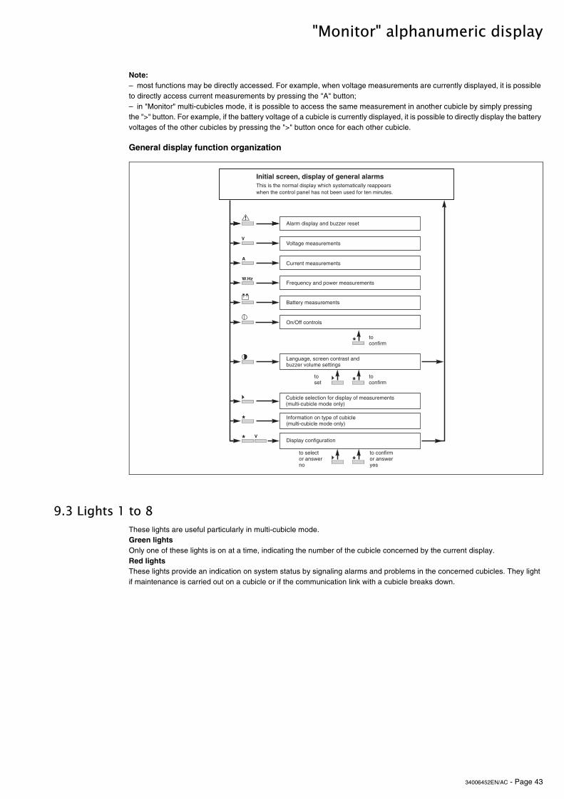
34006452EN/AC - Page 43
"Monitor" alphanumeric display
General display function organization
9.3 Lights 1 to 8
Note: – most functions may be directly accessed. For example, when voltage measurements are currently displayed, it is possible to directly access current measurements by pressing the "A" button;– in "Monitor" multi-cubicles mode, it is possible to access the same measurement in another cubicle by simply pressing the ">" button. For example, if the battery voltage of a cubicle is currently displayed, it is possible to directly display the battery voltages of the other cubicles by pressing the ">" button once for each other cubicle.
These lights are useful particularly in multi-cubicle mode.Green lightsOnly one of these lights is on at a time, indicating the number of the cubicle concerned by the current display.Red lightsThese lights provide an indication on system status by signaling alarms and problems in the concerned cubicles. They light if maintenance is carried out on a cubicle or if the communication link with a cubicle breaks down.
�������"����=��� ������������������>�������������������������������������������������������������������������������������$���������������$���.
�����������������$??��������
5���� ������$�������
�$����������$�������
%��@$�����������������$�������
�����������$�������
-��-�����������
4�� $� �A���������������������$??������$��������� �
�$���������������������������������$�������0�$�����$��������������1
*���������������������$�����0�$�����$��������������1
����������� $������
-
+ ,
�
�
:;3<
>
>
>
-
��������������������
���������������������
>�����
���������
���������>

34006452EN/AC - Page 44
"Monitor" alphanumeric display
9.4 Alarm display and buzzer reset
Display of alarms
List of general alarms
When the control panel has not been used for ten minutes, the alphanumeric display presents a general message indicating the general status of the cubicle or the system.If there are no alarms or problems, and the load is correctly supplied by the inverter, the display indicates:
If there is a problem, the screen first displays a general alarm, then if applicable, a list of secondary alarms may be obtained by successively pressing the "alarms" button ("!"). See the lists below.For the local "Monitor" option, button on the hidden control panel stops the buzzer.For the remote "Monitor" option ("Tele Monitor"), the "!" button stops the buzzer.
Note:The existence of another alarm in the list is indicated by the blinking "!" character at the end of a message. The last alarm in the list is not followed by the blinking "!" character at the end. If the "alarms" button is pressed again, the system returns to the initial screen.
This message is displayed only if the buzzer has been activated. It is a prompt to consult the list of current alarms by pressing the "alarms" ("!") button after having read each message.
The last alarm message is not followed by the blinking "!" character. If the "alarms" ("!") button is pressed again,the system returns to the initial screen.
This is the normal display when there are no alarms or problems and the load is correctly supplied by the inverter.
The load is supplied by the inverter, but a minor problem requiring servicing has occurred. The cause of the problem is contained in the list of secondary alarms (see next page).
The load is supplied by the inverter, but Mains 1 is down or outside tolerances and power is supplied by the battery.
LOAD PROTECTED POWER SUPPLY OK
11
�
�������������������������
��������������������
���������������������������������
��������������
�
�
�
�
������������������������
LOAD PROTECTEDPOWER SUPPLY OK
LOAD PROTECTED PROBLEM... !
MAINS 1 PROBLEM LOAD ON BATTERY !
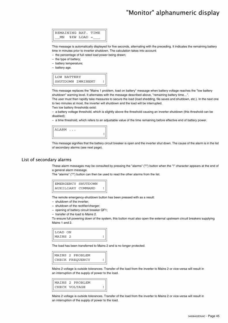
34006452EN/AC - Page 45
"Monitor" alphanumeric display
List of secondary alarms
This message is automatically displayed for five seconds, alternating with the preceding. It indicates the remaining battery time in minutes prior to inverter shutdown. The calculation takes into account:– the percentage of full rated load power being drawn;– the type of battery;– battery temperature;– battery age.
This message replaces the "Mains 1 problem, load on battery" message when battery voltage reaches the "low battery shutdown" warning level. It alternates with the message described above, "remaining battery time…". The user must then rapidly take measures to secure the load (load shedding, file saves and shutdown, etc.). In the next one to two minutes at most, the inverter will shutdown and the load will be interrupted.Two low battery thresholds exist:– a battery voltage threshold, which is slightly above the threshold causing an inverter shutdown (this threshold can be disabled);– a time threshold, which refers to an adjustable value of the time remaining before effective end of battery power.
This message signifies that the battery circuit breaker is open and the inverter shut down. The cause of the alarm is in the list of secondary alarms (see next page).
These alarm messages may be consulted by pressing the "alarms" ("!") button when the "!" character appears at the end of a general alarm message.The "alarms" ("!") button can then be used to read the other alarms from the list.
The remote emergency-shutdown button has been pressed with as a result:– shutdown of the inverter;– shutdown of the rectifier/charger;– opening of battery circuit breaker QF1;– transfer of the load to Mains 2.To ensure full powering down of the system, this button must also open the external upstream circuit breakers supplying Mains 1 and 2.
The load has been transferred to Mains 2 and is no longer protected.
Mains 2 voltage is outside tolerances. Transfer of the load from the inverter to Mains 2 or vice-versa will result in an interruption of the supply of power to the load.
Mains 2 voltage is outside tolerances. Transfer of the load from the inverter to Mains 2 or vice-versa will result in an interruption of the supply of power to the load.
REMAINING BAT. TIME __MN %KW LOAD =___
LOW BATTERY SHUTDOWN IMMINENT !
! ALARM ...
EMERGENCY SHUTDOWN AUXILIARY COMMAND !
LOAD ON MAINS 2 !
MAINS 2 PROBLEM CHECK FREQUENCY !
MAINS 2 PROBLEM CHECK VOLTAGE !
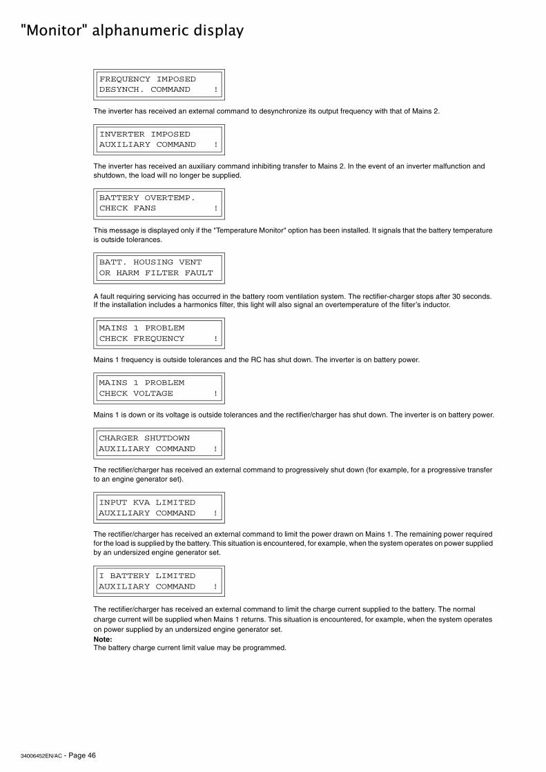
34006452EN/AC - Page 46
"Monitor" alphanumeric display
The inverter has received an external command to desynchronize its output frequency with that of Mains 2.
The inverter has received an auxiliary command inhibiting transfer to Mains 2. In the event of an inverter malfunction and shutdown, the load will no longer be supplied.
This message is displayed only if the "Temperature Monitor" option has been installed. It signals that the battery temperature is outside tolerances.
A fault requiring servicing has occurred in the battery room ventilation system. The rectifier-charger stops after 30 seconds.If the installation includes a harmonics filter, this light will also signal an overtemperature of the filter’s inductor.
Mains 1 frequency is outside tolerances and the RC has shut down. The inverter is on battery power.
Mains 1 is down or its voltage is outside tolerances and the rectifier/charger has shut down. The inverter is on battery power.
The rectifier/charger has received an external command to progressively shut down (for example, for a progressive transfer to an engine generator set).
The rectifier/charger has received an external command to limit the power drawn on Mains 1. The remaining power required for the load is supplied by the battery. This situation is encountered, for example, when the system operates on power supplied by an undersized engine generator set.
The rectifier/charger has received an external command to limit the charge current supplied to the battery. The normal charge current will be supplied when Mains 1 returns. This situation is encountered, for example, when the system operates on power supplied by an undersized engine generator set.Note:The battery charge current limit value may be programmed.
FREQUENCY IMPOSEDDESYNCH. COMMAND !
INVERTER IMPOSEDAUXILIARY COMMAND !
BATTERY OVERTEMP.CHECK FANS !
BATT. HOUSING VENTOR HARM FILTER FAULT
MAINS 1 PROBLEMCHECK FREQUENCY !
MAINS 1 PROBLEMCHECK VOLTAGE !
CHARGER SHUTDOWNAUXILIARY COMMAND !
INPUT KVA LIMITEDAUXILIARY COMMAND !
I BATTERY LIMITEDAUXILIARY COMMAND !
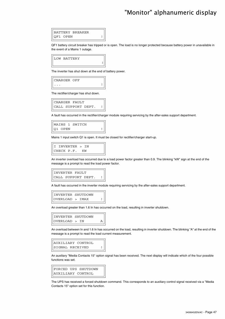
34006452EN/AC - Page 47
"Monitor" alphanumeric display
QF1 battery circuit breaker has tripped or is open. The load is no longer protected because battery power in unavailable in the event of a Mains 1 outage.
The inverter has shut down at the end of battery power.
The rectifier/charger has shut down.
A fault has occurred in the rectifier/charger module requiring servicing by the after-sales support department.
Mains 1 input switch Q1 is open. It must be closed for rectifier/charger start-up.
An inverter overload has occurred due to a load power factor greater than 0.9. The blinking "kW" sign at the end of the message is a prompt to read the load power factor.
A fault has occurred in the inverter module requiring servicing by the after-sales support department.
An overload greater than 1.6 In has occurred on the load, resulting in inverter shutdown.
An overload between In and 1.6 In has occurred on the load, resulting in inverter shutdown. The blinking "A" at the end of the message is a prompt to read the load current measurement.
An auxiliary "Media Contacts 15" option signal has been received. The next display will indicate which of the four possible functions was set.
The UPS has received a forced shutdown command. This corresponds to an auxiliary control signal received via a "Media Contacts 15" option set for this function.
BATTERY BREAKER QF1 OPEN !
LOW BATTERY!
CHARGER OFF... !
CHARGER FAULTCALL SUPPORT DEPT. !
MAINS 1 SWITCHQ1 OPEN !
I INVERTER > INCHECK P.F. KW
INVERTER FAULTCALL SUPPORT DEPT. !
INVERTER SHUTDOWNOVERLOAD > IMAX !
INVERTER SHUTDOWNOVERLOAD > IN A
AUXILIARY CONTROLSIGNAL RECEIVED !
FORCED UPS SHUTDOWNAUXILIARY CONTROL
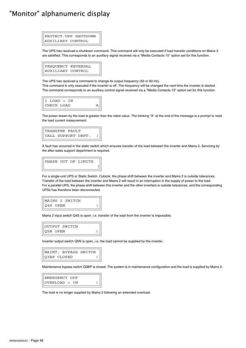
34006452EN/AC - Page 48
"Monitor" alphanumeric display
The UPS has received a shutdown command. This command will only be executed if load transfer conditions on Mains 2 are satisfied. This corresponds to an auxiliary signal received via a "Media Contacts 15" option set for this function.
The UPS has received a command to change its output frequency (50 or 60 Hz).This command is only executed if the inverter is off. The frequency will be changed the next time the inverter is started. The command corresponds to an auxiliary control signal received via a "Media Contacts 15" option set for this function
The power drawn by the load is greater than the rated value. The blinking "A" at the end of the message is a prompt to read the load current measurement.
A fault has occurred in the static switch which ensures transfer of the load between the inverter and Mains 2. Servicing by the after-sales support department is required.
For a single-unit UPS or Static Switch Cubicle, the phase shift between the inverter and Mains 2 is outside tolerances. Transfer of the load between the inverter and Mains 2 will result in an interruption in the supply of power to the load.For a parallel UPS, the phase shift between this inverter and the other inverters is outside tolerances, and the corresponding UPSs has therefore been disconnected.
Mains 2 input switch Q4S is open, i.e. transfer of the load from the inverter is impossible.
Inverter output switch Q5N is open, i.e. the load cannot be supplied by the inverter.
Maintenance bypass switch Q3BP is closed. The system is in maintenance configuration and the load is supplied by Mains 2.
The load is no longer supplied by Mains 2 following an extended overload.
PROTECT.UPS SHUTDOWNAUXILIARY CONTROL
FREQUENCY REVERSALAUXILIARY CONTROL
I LOAD > INCHECK LOAD A
TRANSFER FAULTCALL SUPPORT DEPT. !
PHASE OUT OF LIMITS!
MAINS 2 SWITCHQ4S OPEN !
OUTPUT SWITCHQ5N OPEN !
MAINT. BYPASS SWITCHQ3BP CLOSED !
EMERGENCY OFFOVERLOAD > IN !
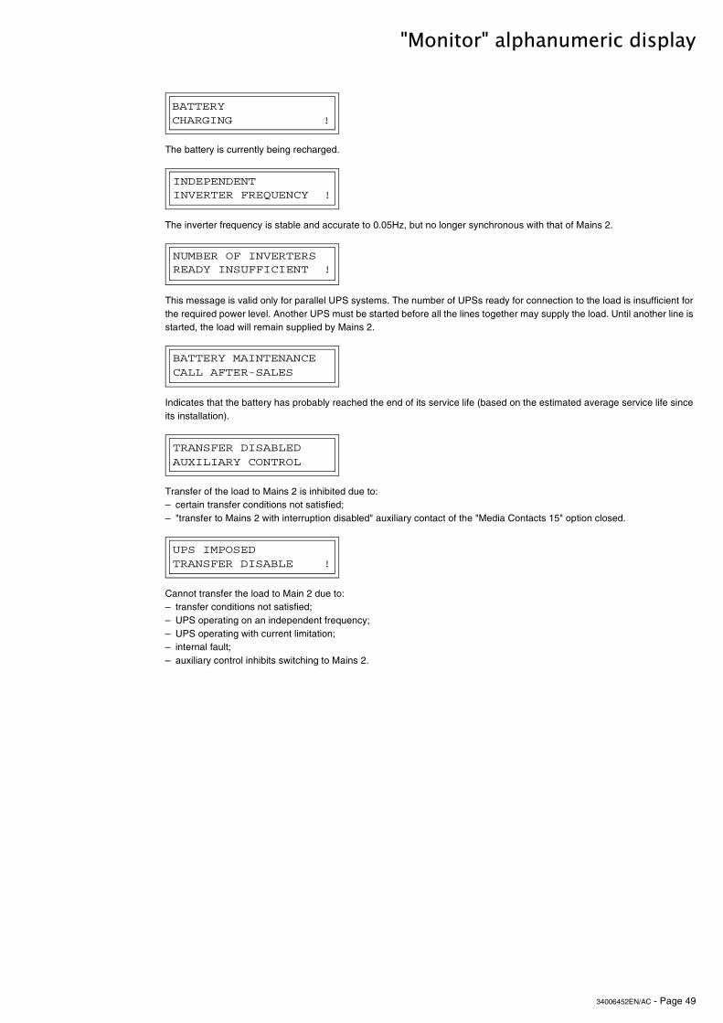
34006452EN/AC - Page 49
"Monitor" alphanumeric display
The battery is currently being recharged.
The inverter frequency is stable and accurate to 0.05Hz, but no longer synchronous with that of Mains 2.
This message is valid only for parallel UPS systems. The number of UPSs ready for connection to the load is insufficient for the required power level. Another UPS must be started before all the lines together may supply the load. Until another line is started, the load will remain supplied by Mains 2.
Indicates that the battery has probably reached the end of its service life (based on the estimated average service life since its installation).
Transfer of the load to Mains 2 is inhibited due to:– certain transfer conditions not satisfied;– "transfer to Mains 2 with interruption disabled" auxiliary contact of the "Media Contacts 15" option closed.
Cannot transfer the load to Main 2 due to:– transfer conditions not satisfied;– UPS operating on an independent frequency;– UPS operating with current limitation;– internal fault;– auxiliary control inhibits switching to Mains 2.
BATTERY CHARGING !
INDEPENDENTINVERTER FREQUENCY !
NUMBER OF INVERTERSREADY INSUFFICIENT !
BATTERY MAINTENANCECALL AFTER-SALES
TRANSFER DISABLEDAUXILIARY CONTROL
UPS IMPOSEDTRANSFER DISABLE !
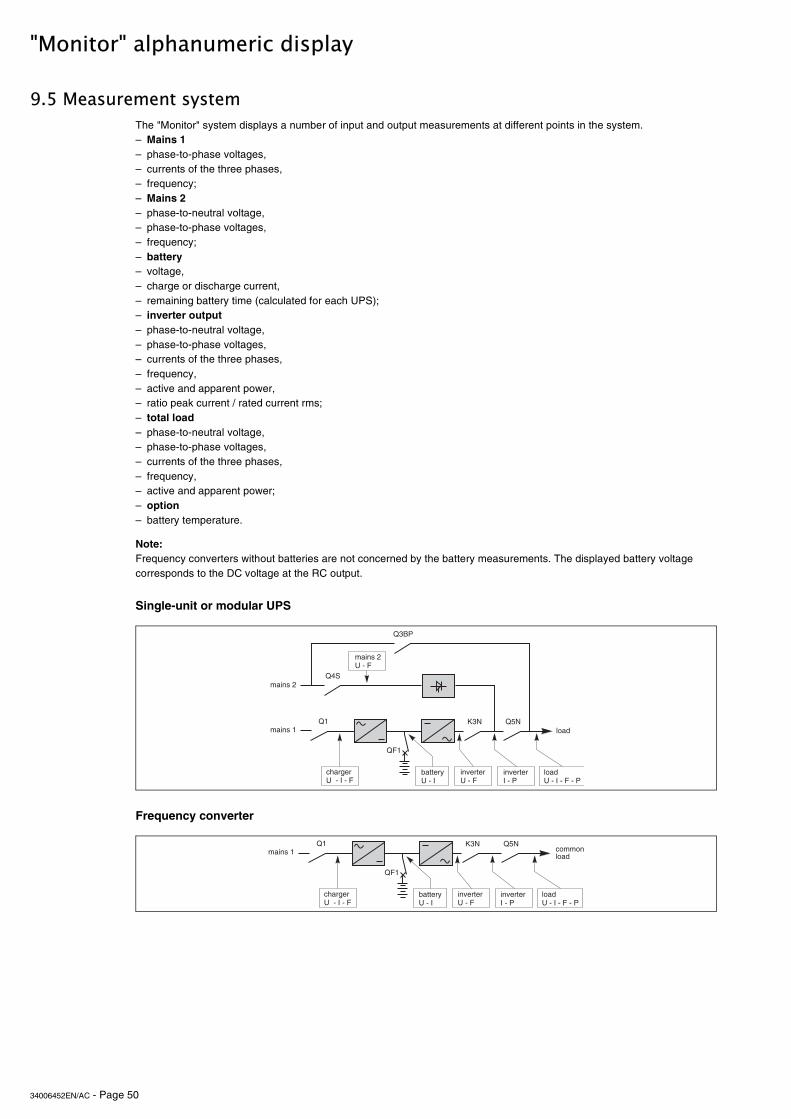
34006452EN/AC - Page 50
"Monitor" alphanumeric display
9.5 Measurement system
Single-unit or modular UPS
Frequency converter
The "Monitor" system displays a number of input and output measurements at different points in the system.– Mains 1– phase-to-phase voltages,– currents of the three phases,– frequency;– Mains 2– phase-to-neutral voltage,– phase-to-phase voltages,– frequency;– battery– voltage,– charge or discharge current,– remaining battery time (calculated for each UPS);– inverter output– phase-to-neutral voltage,– phase-to-phase voltages,– currents of the three phases,– frequency,– active and apparent power,– ratio peak current / rated current rms;– total load– phase-to-neutral voltage,– phase-to-phase voltages,– currents of the three phases,– frequency,– active and apparent power;– option– battery temperature.
Note:Frequency converters without batteries are not concerned by the battery measurements. The displayed battery voltage corresponds to the DC voltage at the RC output.
������� ����
�������
�� �!"
�%�
���
�)#
B�"
��������*���
�������&���%
���� ��&����*���%
������&���*
��������&���%
����&���*���%���
������� ����������
�� �!"
�%�
B�"
��������*���
���� ��&����*���%
������&���*
��������&���%
����&���*���%���
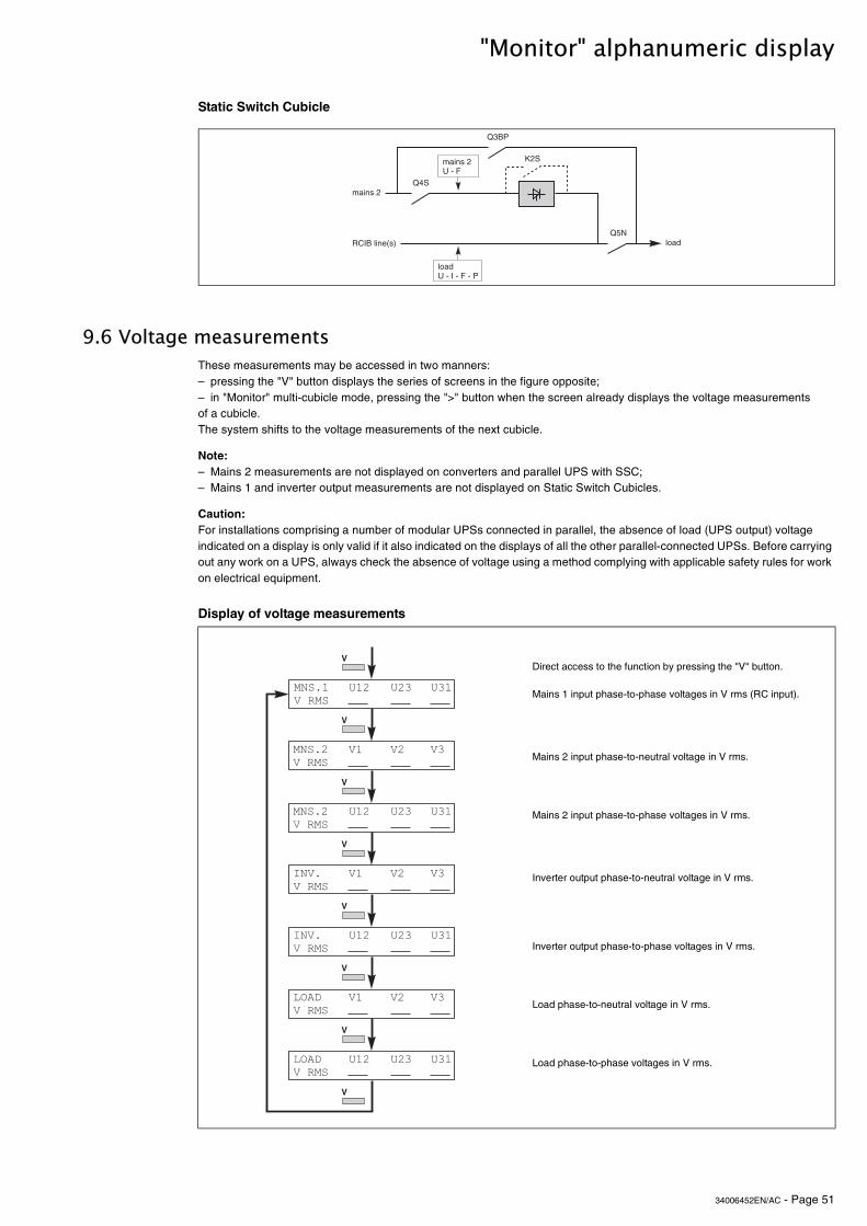
34006452EN/AC - Page 51
"Monitor" alphanumeric display
Static Switch Cubicle
9.6 Voltage measurements
Display of voltage measurements
These measurements may be accessed in two manners:– pressing the "V" button displays the series of screens in the figure opposite;– in "Monitor" multi-cubicle mode, pressing the ">" button when the screen already displays the voltage measurements of a cubicle. The system shifts to the voltage measurements of the next cubicle.
Note:– Mains 2 measurements are not displayed on converters and parallel UPS with SSC;– Mains 1 and inverter output measurements are not displayed on Static Switch Cubicles.
Caution:For installations comprising a number of modular UPSs connected in parallel, the absence of load (UPS output) voltage indicated on a display is only valid if it also indicated on the displays of all the other parallel-connected UPSs. Before carrying out any work on a UPS, always check the absence of voltage using a method complying with applicable safety rules for work on electrical equipment.
Direct access to the function by pressing the "V" button.
Mains 1 input phase-to-phase voltages in V rms (RC input).
Mains 2 input phase-to-neutral voltage in V rms.
Mains 2 input phase-to-phase voltages in V rms.
Inverter output phase-to-neutral voltage in V rms.
Inverter output phase-to-phase voltages in V rms.
Load phase-to-neutral voltage in V rms.
Load phase-to-phase voltages in V rms.
:�*������0�1 ����
�������
�!"
���
�)#
�������&���%
����&���*���%���
B�#
��� �!����
��� �!����
��� ��" �"�
!� !� !"
��� �!����
��� ��" �"�
#�! !����
!� !� !"
��� ��" �"�#�! !����
���$!����
!� !� !"
��� ��" �"����$!����
-
-
-
-
-
-
-
-
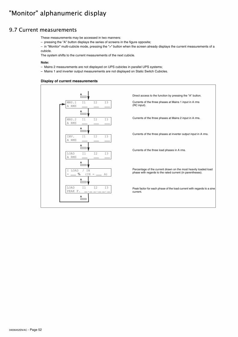
34006452EN/AC - Page 52
"Monitor" alphanumeric display
9.7 Current measurements
Display of current measurements
These measurements may be accessed in two manners:– pressing the "A" button displays the series of screens in the figure opposite;– in "Monitor" multi-cubicle mode, pressing the ">" button when the screen already displays the current measurements of a cubicle. The system shifts to the current measurements of the next cubicle.
Note:– Mains 2 measurements are not displayed on UPS cubicles in parallel UPS systems;– Mains 1 and inverter output measurements are not displayed on Static Switch Cubicles.
Direct access to the function by pressing the "A" button.
Currents of the three phases at Mains 1 input in A rms (RC input).
Currents of the three phases at Mains 2 input in A rms.
Currents of the three phases at inverter output input in A rms.
Currents of the three load phases in A rms.
Percentage of the current drawn on the most heavily loaded load phase with regards to the rated current (in parentheses).
Peak factor for each phase of the load current with regards to a sine current.
��� ������
��� ������
#� #� #"
#� #� #"
#����$��%�#�&
�
�
�
�
�
�
�
#� #� #"
#� #� #"#�! �����
���$�����
� �#��&�������
#� #� #"���$'����(
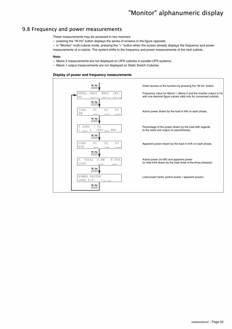
34006452EN/AC - Page 53
"Monitor" alphanumeric display
9.8 Frequency and power measurements
Display of power and frequency measurements
These measurements may be accessed in two manners:– pressing the "W.Hz" button displays the series of screens in the figure opposite;– in "Monitor" multi-cubicle mode, pressing the ">" button when the screen already displays the frequency and power measurements of a cubicle. The system shifts to the frequency and power measurements of the next cubicle.
Note:– Mains 2 measurements are not displayed on UPS cubicles in parallel UPS systems;– Mains 1 output measurements are not displayed on Static Switch Cubicles.
Direct access to the function by pressing the "W.Hz" button.
Frequency value for Mains 1, Mains 2 and the inverter output in Hz with one decimal figure values valid only for concerned cubicle).
Active power drawn by the load in kW on each phase.
Percentage of the power drawn by the load with regards to the rated unit output (in parentheses).
Apparent power drawn by the load in kVA on each phase.
Active power (in kW) and apparent power (in total kVA drawn by the load (total of the three phases)).
Load power factor (active power / apparent power).
(��) *+
���$�,
���� ���� #�!
'� '� '"
' ���������$
'�,���(�-������$�' ( ���&
:;3<
'� '� '"
'����$��%�'.&�����/
���$�!�
:;3<
:;3<
:;3<
:;3<
:;3<
:;3<
�'�&�����,�
' �, ' �!�
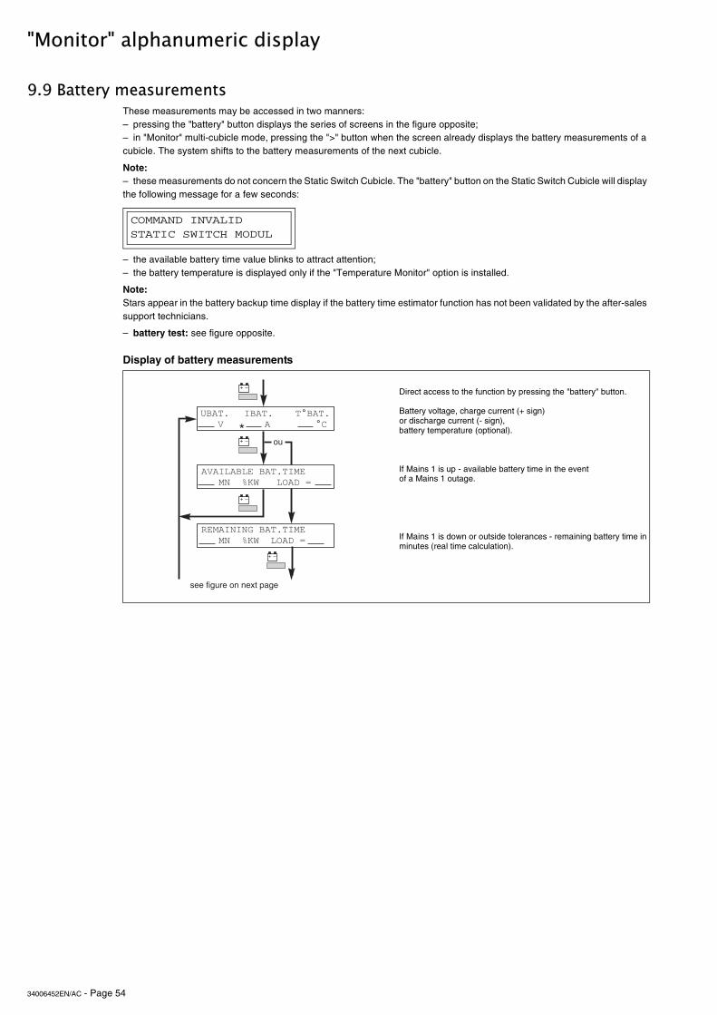
34006452EN/AC - Page 54
"Monitor" alphanumeric display
9.9 Battery measurements
Display of battery measurements
These measurements may be accessed in two manners:– pressing the "battery" button displays the series of screens in the figure opposite;– in "Monitor" multi-cubicle mode, pressing the ">" button when the screen already displays the battery measurements of a cubicle. The system shifts to the battery measurements of the next cubicle.
Note:– these measurements do not concern the Static Switch Cubicle. The "battery" button on the Static Switch Cubicle will display the following message for a few seconds:
– the available battery time value blinks to attract attention;– the battery temperature is displayed only if the "Temperature Monitor" option is installed.
Note:Stars appear in the battery backup time display if the battery time estimator function has not been validated by the after-sales support technicians.
– battery test: see figure opposite.
Direct access to the function by pressing the "battery" button.
Battery voltage, charge current (+ sign) or discharge current (- sign), battery temperature (optional).
If Mains 1 is up - available battery time in the event of a Mains 1 outage.
If Mains 1 is down or outside tolerances - remaining battery time in minutes (real time calculation).
COMMAND INVALIDSTATIC SWITCH MODUL
+ ,
���� ���!
�!�#��������� �#���������/�,������$�&
#��� ����
�0��� ���0-
+ , �$
+ ,
+ ,
����#�#������ �#���������/�,�����$�&
=
������ $��������C��� �
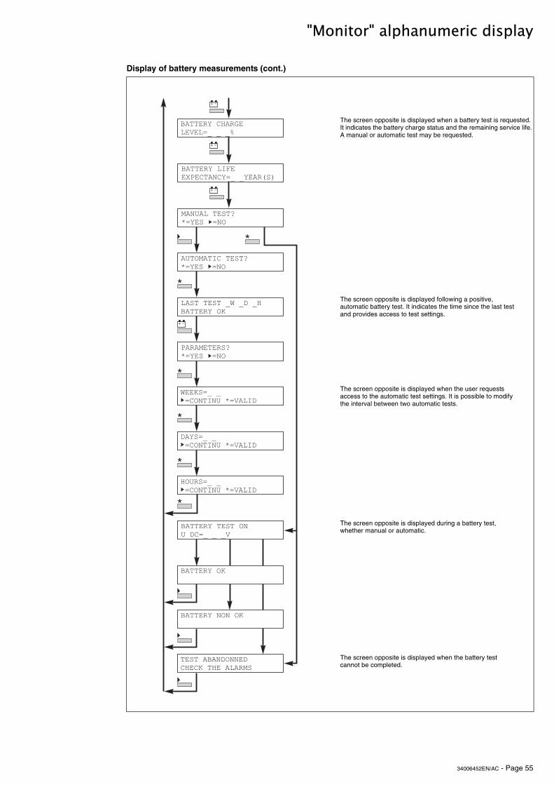
34006452EN/AC - Page 55
"Monitor" alphanumeric display
Display of battery measurements (cont.)
The screen opposite is displayed when a battery test is requested. It indicates the battery charge status and the remaining service life. A manual or automatic test may be requested.
The screen opposite is displayed following a positive, automatic battery test. It indicates the time since the last test and provides access to test settings.
The screen opposite is displayed when the user requests access to the automatic test settings. It is possible to modify the interval between two automatic tests.
The screen opposite is displayed during a battery test, whether manual or automatic.
The screen opposite is displayed when the battery test cannot be completed.
������1�-*������!��&2�2�2/
������1��#(��3'�-���-1&2�21������
�����������45&1����&��
������1����������$-&2�2�2!
���������$����$-*�-���*��������
+ ,
+ ,
������1���
=
+ ,
+ ,
=
=
=
=
=
������1�������
�������#-�����45&1����&��
����������2,�2$�2*������1���
'���������45&1����&��
,����&2�2�&-���#���5&!��#$
$�1�&2�2�&-���#���5&!��#$
*����&2�2�&-���#���5&!��#$
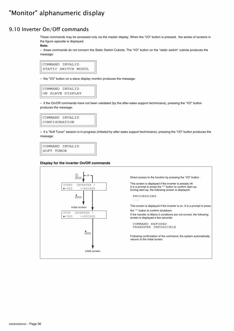
34006452EN/AC - Page 56
"Monitor" alphanumeric display
9.10 Inverter On/Off commands
Display for the inverter On/Off commands
These commands may be accessed only via the master display. When the "I/O" button is pressed, the series of screens in the figure opposite is displayed.Note:– these commands do not concern the Static Switch Cubicle. The "I/O" button on the "static switch" cubicle produces the message:
– the "I/O" button on a slave display monitor produces the message:
– if the On/Off commands have not been validated (by the after-sales support technicians), pressing the "I/O" button produces the message:
– if a "Soft Tunor" session is in progress (initiated by after-sales support technicians), pressing the "I/O" button produces the message:
Direct access to the function by pressing the "I/O" button .
This screen is displayed if the inverter is already off. It is a prompt to press the "*" button to confirm start-up. During start-up, the following screen is displayed:
PROCESSING ...
This screen is displayed if the inverter is on. It is a prompt to press
the "*" button to confirm shutdown.
If the transfer to Mains 2 conditions are not correct, the following screen is displayed a few seconds:
COMMAND REFUSED TRANSFER IMPOSSIBLE
Following confirmation of the command, the system automatically returns to the initial screen.
COMMAND INVALIDSTATIC SWITCH MODUL
COMMAND INVALIDON SLAVE DISPLAY
COMMAND INVALIDCONFIGURATION
COMMAND INVALIDSOFT TUNOR
>
>�������#�!������4�&1������6&��-�'�
��
��������������
��������������
>���'��#�!������4�&1������6&��-�'�
>
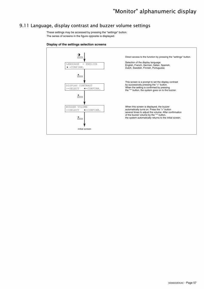
34006452EN/AC - Page 57
"Monitor" alphanumeric display
9.11 Language, display contrast and buzzer volume settings
Display of the settings selection screens
These settings may be accessed by pressing the "settings" button. The series of screens in the figure opposite is displayed.
Direct access to the function by pressing the "settings" button.
Selection of the display language: English, French, German, Italian, Spanish, Dutch, Swedish, Finnish, Portuguese.
This screen is a prompt to set the display contrast by successively pressing the ">" button. When the setting is confirmed by pressing the "*" button, the system goes on to the buzzer.
When this screen is displayed, the buzzer automatically turns on. Press the ">" button several times to adjust the volume. After confirmation of the buzzer volume by the "*" button, the system automatically returns to the initial screen.
����������&�����#�*��&-��(#��
��������������
>
$#�'��1�-�������6&����-�����&-��(#�� >
��++���!�����6&����-�����&-��(#�� >
>
>
>
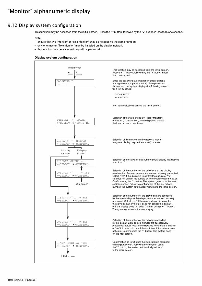
34006452EN/AC - Page 58
"Monitor" alphanumeric display
9.12 Display system configuration
Display system configuration
This function may be accessed from the initial screen. Press the "*" button, followed by the "V" button in less than one second.
Note:– ensure that two "Monitor" or "Tele Monitor" units do not receive the same number;– only one master "Tele Monitor" may be installed on the display network;– this function may be accessed only with a password.
This function may be accessed from the initial screen. Press the "*" button, followed by the "V" button in less than one second.
Enter the password (a combination of four buttons among the control panel buttons). If the password is incorrect, the system displays the following screen for a few seconds:
INCORRECT PASSWORD
then automatically returns to the initial screen.
Selection of the type of display: local ("Monitor") or distant ("Tele Monitor"). If the display is distant, the local buzzer is deactivated.
Selection of display role on the network: master (only one display may be the master) or slave.
Selection of the slave display number (multi-display installation) from 1 to 10.
Selection of the numbers of the cubicles that the display must control. Ten cubicle numbers are successively presented. Select "yes" if the display is to control the cubicle or "no" if it does not control the cubicle or if the cubicle does not exist. Confirm using the "*" button. The system goes on to the next cubicle number. Following confirmation of the last cubicle number, the system automatically returns to the initial screen.
Selection of the numbers of the slave displays controlled by the master display. Ten display number are successively presented. Select "yes" if the master display is to control the slave display or "no" if it does not control the display or if the display does not exist. Confirm using the "*" button. The system goes on to the next display.
Selection of the numbers of the cubicles controlled by the display. Eight cubicle number are successively presented. Select "yes" if the display is to control the cubicleor "no" if it does not control the cubicle or if the cubicle does not exist. Confirm using the "*" button. The system goes on the next screen.
Confirmation as to whether the installation is equipped with a giant screen. Following confirmation using the "*" button, the system automatically returns to the initial screen.
'���,��$�4�&
$#�'��1��&��������6&����-����&-��(#�� >
$#�'��1��������&6&����-����&-��(#�� >
-��#-����0�����&�1��6&����-����&-��(#�� >
>
��������������
-
�����������������
>
��������������
$#�'��1��0����&�1��6&����-����&-��(#��
-��#-����0����&�1��6&����-����&-��(#��
>�#�����$#�'��1�&1��6&����-����&-��(#��
��������������
>
����������������
>$#�'��1��&����-��6&����-����&-��(#��
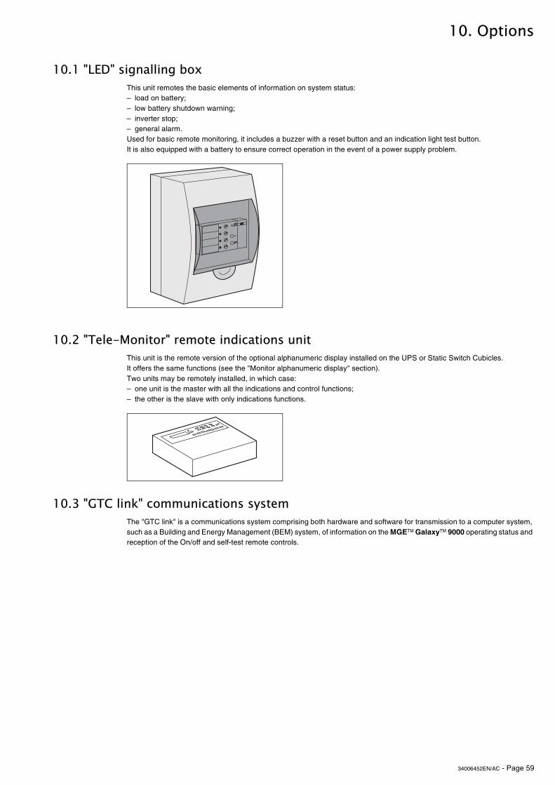
34006452EN/AC - Page 59
10. Options
10.1 "LED" signalling box
10.2 "Tele-Monitor" remote indications unit
10.3 "GTC link" communications system
This unit remotes the basic elements of information on system status:– load on battery;– low battery shutdown warning;– inverter stop;– general alarm.Used for basic remote monitoring, it includes a buzzer with a reset button and an indication light test button.It is also equipped with a battery to ensure correct operation in the event of a power supply problem.
This unit is the remote version of the optional alphanumeric display installed on the UPS or Static Switch Cubicles.It offers the same functions (see the "Monitor alphanumeric display" section).Two units may be remotely installed, in which case:– one unit is the master with all the indications and control functions;– the other is the slave with only indications functions.
The "GTC link" is a communications system comprising both hardware and software for transmission to a computer system, such as a Building and Energy Management (BEM) system, of information on the MGETM GalaxyTM 9000 operating status and reception of the On/off and self-test remote controls.
����

34006452EN/AC - Page 60
Options
10.4 "Vision" display
10.5 "Remote vision" display
10.6 Insulating and Mains 1, Mains 2 and load voltage matching transformer
The "Vision" display may be installed in all types of cubicles (UPS or Static Switch Cubicle).The "Vision" display can operate in two different modes:– mono-cubicle: the "Vision" display monitors only the cubicle in which it is installed;– multi-cubicle: "Vision" display can monitor all system cubicles (up to eight maximum). In this mode, the system is equipped with only one "Vision" display which may be installed in any of the cubicles.
Installed in a special enclosure, the "Remote vision" display provides the user with remote indications on system status.
This transformer may be used to match Mains 2 voltage to that of the inverter, to create galvanic insulation between the load and the Mains or to create the appropriate neutral system.
�� ��������6���������������� ���
��������������
����������
����
���
���
�
����������� !"����
���
��#� $�%$��&�����' (� �����$�#�$
)��(�$��*
&+��,,��*
�����-� �(�!�
�� ��)
�.�
��
�/&0��1�1/����/�2��2����
��(�
�$��(,
3!$ !�'��!�
���� ,� �,
4��� 5 ��
&�����+
�!#�����
&+��,,
3�����
������
�� ��������6���������������� ���
��������������
����������
����
���
���
�
����������� !"����
���
��#� $�%$��&�����' (� �����$�#�$
)��(�$��*
&+��,,��*
�����-� �(�!�
�� ��)
�.�
��
�/&0��1�1/����/�2��2����
��(�
�$��(,
3!$ !�'��!�
���� ,� �,
4��� 5 ��
&�����+
�!#�����
&+��,,
3�����
������
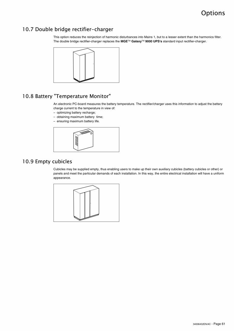
34006452EN/AC - Page 61
Options
10.7 Double bridge rectifier-charger
10.8 Battery "Temperature Monitor"
10.9 Empty cubicles
This option reduces the reinjection of harmonic disturbances into Mains 1, but to a lesser extent than the harmonics filter.The double bridge rectifier-charger replaces the MGETM GalaxyTM 9000 UPS's standard input rectifier-charger.
An electronic PC-board measures the battery temperature. The rectifier/charger uses this information to adjust the battery charge current to the temperature in view of:– optimizing battery recharge;– obtaining maximum battery time;– ensuring maximum battery life.
Cubicles may be supplied empty, thus enabling users to make up their own auxiliary cubicles (battery cubicles or other) or panels and meet the particular demands of each installation. In this way, the entire electrical installation will have a uniform appearance.

34006452EN/AC


![INDEX [] · 2015-05-26 · Ablerex is Power Converter|Three Phase UPS Three Phase UPS 01|02 BRIC ST 30KVA/30KW, 60KVA/60KW B BRIC 30S 30KVA/30KW Module Taurus Series 10KVA~60KVA](https://img.pdfslide.us/doc/110x75/5e335211b4027427034a241d/index-2015-05-26-ablerex-is-power-converterioethree-phase-ups-three-phase.jpg)