Embed Size (px)
Citation preview

ADI 5106G
Single StationRemote Alarm
Controls Corporation of America1501 Harpers Road • Virginia Beach, VA 23454
To Order Call 1-800-225-0473 or 757-422-8330 • Fax 757-422-3125www.concoa.com
INSTALLATION AND OPERATING INSTRUCTIONS
Carefully Read These Instructions Before Operating
June 2005Supersedes October 2003
®
Certified ISO 9001:2000
529 5106-01-120529 5106-01-220

-2-
DESCRIPTION OF PRODUCTThe Single Station Remote Alarm is capable of operating at either 120VAC or 220VAC depending on which wall mounted power supply it was ordered with. It is capable of providing operating status for the left and right banks of one CONCOA Switchover system. The Single Station Remote Alarm provides power to the Switchover System to operate the status lights and the pressure switches.
An AutoSwitch product that is configured with the alarm option is equipped with two pressure switch gauges, two sets of status indicators, and a power status indicator. A 526/527 Series Switchover System has two pressure switch gauges. The CONCOA IntelliSwitch System is a self-powered unit with local visual indication of system status. The Single System Remote alarm provides remote status indication for the IntelliSwitch.
The front panel of the Remote Alarm consists of four (4) status indicator lights, an “Alarm Silence” button, and an audible Alarm. See Figure 1. In addition to the front panel, the left side of the Remote Alarm has a power jack connector where the power supply cable is connected. At the bottom of the Alarm are two (2) connectors where the CONCOA Switchover and Output Devices are connected.
The Single Station Remote Alarm controls one (1) set of relay contacts that are brought to the Output Connector so they may be used to control an external device.
The status indicator lights are organized into pairs representing the Left Bank and Right Bank of a CONCOA Switchover System. When a system is operating normally the status indicator light will be green. If the pressure should drop below the preset value of the CONCOA Switchover System, the audible alarm will sound and the light corresponding to the specific Bank will turn from green to red. When this happens, the output relays will activate. It is sometimes desirable to silence the audible alarm prior to the alarm condition being fixed. Pressing the “Silence” button will accomplish this. The status indicator lights and the relays will remain activated until the alarm condition is corrected. If the second bank on the same CONCOA Switchover System generates an alarm while the first Bank is still in an alarm condition the other status indicator light in that system will turn from green to red and the audible alarm that was previously silenced will sound again.
Correcting the low pressure condition will return the status lights back to green, and deactivate the relay.
Audible Alarm Silence
Audible Alarm
Power Jack
Red “Alarm” Indicators
Green “Normal” Indicators
Figure 1
Relay Contact Output
Switchover System connector

-3-
INTENDED USE OF PRODUCTThe Single Station Remote Alarm is used to monitor and report the status of any CONCOA Switchover Systems. The Alarm can be configured to operate with either normally open or normally closed pressure switch contacts. The Alarm contains a set of relay contacts that can be used to control any device that can be activated using a normally open or normally closed switch. One example of such a device would be the CONCOA telephone dialer (PN 5295306).
Connections to the Alarm are made through input and output connectors. Customer supplied cables are easily soldered to the connectors prior to plugging the connectors into the Alarm. For connector pin assignments please refer to the “CONNECTING THE ALARM” section of this manual.
USER RESPONSIBILITYService to this product should only be performed by CONCOA or an authorized CONCOA agent. Requests for service may be made through CONCOA CUSTOMER SERVICE at 1-800-225-0473. Written requests may be made using CONCOA’s FAX number at 1-757-422-3125 or CONCOA’s E-MAIL at [email protected].
CONCOA accepts no responsibility for damage or injury if this product is modified in any way.
CONCOA assumes/accepts no liability or responsibility for damage to individuals or equipment that may occur when using this product.
GENERAL SAFETY PRACTICESBasic safety precautions must be followed to reduce the risk of fire, electrical shock or injury.
a. Connect the Alarm to the correct line voltage. The product is supplied with either a 120 VAC or 220VAC wall mount power supply.
b. While the Alarm is dust and moisture resistant, it should be installed in a location where it will not be subjected to rain or high concentrations of dust. Never pour or spray liquids directly onto the product.
c. Install the Alarm where the ambient temperature range while operating is between 0°F and 140°F.d. Do not install the product in hazardous locations.e. If product appears damaged in any way, do not use and request service from CONCOA.f. Do not attempt to operate the Alarm with the cover off.
CONNECTING THE ALARMTo connect the Single Station Remote Alarm to a CONCOA Switchover System, an interface cable must be made. The CONCOA Switchover Systems are shipped with a connector that is used for this cable. Two connectors are provided with the alarm. One is used to connect to the CONCOA Switchover System and the other is to connect to the output relay contacts.
To perform the assembly task you will need a soldering station or pencil, rosin core solder, and a wire stripper. It would also be helpful to have a vise to hold a connector while soldering the wires to it.
OPTION 1: For AutoSwitch and IntelliSwitch Systems that use a 6 pin circular connector.It will be necessary to obtain a 6 conductor cable. The length of the cable is determined by the application, but should be limited to no longer than 1500 feet. It is recommended that 22 AWG stranded wire be used. (Alpha #5006C is an acceptable type.)

-4-
OPTION 1 (continued)Cut the 6 conductor cable to length. Remove the outer jacket of the cable to expose approximately 11⁄2 inches of the internal conductors. Strip away 1⁄4 inch of the insulation on each of the 6 conductors. Tin the leads of the conductors. Slide the protective cover, cable retainer, and locking nut for the circular connector over one end of the cable as shown in Figure 2.
Using the pin assignments shown in Table 1 and the connector view in Figure 3, solder the wires to the appropriate pins. After soldering is complete attache the cable cover, cable retainer, and locking nut to each of the circular connector plugs.
Plug the one side of the cable into the Remote Alarm and secure it by turning the locking nut until it locks. Plug the other circular connector into the AutoSwitch securing it by turning the locking nut until it locks.
Figure 2
Cable Retainer
Cable Retainer Tabs
Cable Cover PlugLocking Nut
Table 1
SYSTEMAutoSwitch Connector
Pin #
Remote Alarm Connector
Pin #Function
LEFT BANK1 1 LBSW status2 2 alarm
RIGHT BANK4 4 RBSW status5 5 alarm3 3 +126 6 Gnd
notch
Figure 3 - View A-A
Connector pins (Figure 3) viewed from this side�

-5-
OPTION 2: For Switchover Systems that have a 4 pin circular connector.It will be necessary to obtain a 4 conductor cable. The length of the cable is determined by the application but should be limited to no longer than 1500 feet. It is recommended that 22 AWG stranded wire be used. (Alpha #5004C or Belden #8444 are acceptable types.)
Cut the 4 conductor cable to length. Remove the outer jacket of the cable to expose approximately 11⁄2 inches of the internal conductors. Strip away 1⁄4 inch of the insulation on each of the 4 conductors. Tin the leads of the conductors. Slide the protective cover, cable retainer, and locking nut for the circular connector over one end of the cable as shown in Figure 4.
Using the pin assignments shown in Table 2 and the connector views in Figure 5 and Figure 6, solder the wires to the appropriate pins. After soldering is complete attach the cable cover, cable retainer, and locking nut to each of the circular connector plugs.
Plug the Input Connector side of the cable (6 pin connector) into the Remote Alarm and secure it by turning the locking nut until it locks. Plug the 4 pin circular connector into the Switchover securing it by turning the locking nut until it locks.
notchnotch
Figure 4
Cable Retainer Tabs
Cable Cover Cable Retainer Locking Nut Plug
Figure 5 - View A-A Figure 6 - View A-A
SYSTEMSwitchover
Connector Pin #Remote Alarm
Connector Pin #Function
LEFT BANK3 1 LBSW status--- --- alarm
RIGHT BANK2 4 RBSW status--- --- alarm1 3 +124 6 Gnd
Table 2
Connector pins (Figures 5 and 6) viewed from this side

-6-
CONNECTING THE OUTPUTThe Single Station Remote Alarm activates a set of relay contacts in response to an alarm condition. This set of relay contacts can be connected to any external device that is activated by the opening or closing of a switch. Examples would be CONCOA’s telephone dialer, a Warning Light, an external buzzer, or another monitoring or alarm system. Whatever the connecting device, care must be taken not exceed the rating of the relay contacts (Table 3). Refer to Table 4 for the pin assignments for the Output Connector.
Relay Contact Rating24 VDC 1 amp Resistive Load115 VAC 0.5 amp Resistive Load
Table 3
Figure 7
Pin Number Function Contact1
Relay OutputCommon (C)
2 Normally Closed (N.C.)3 Normally Open (N.O.)4 Unused
Table 4
notch
Cable Retainer Tabs
Cable Cover Cable Retainer Locking Nut Plug
Connector pins (Figure 8) viewed from this side
Figure 8 - View A-A

-7-
CONFIGURING THE REMOTE ALARMThe single station remote alarm can be configured to work with any of the CONCOA dual regulator switchovers or autoswitch systems whether they use a normally open (N.O.) or a normally closed (N.C.) pressure switch. By definition, a normally open pressure switch contacts are “open” when the pressure switch needle is below the trip point. The single station remote alarm is factory set to operate with normally open (N.O.) pressure switches for the dual regulator switchover (see DIP switch setting A).
DIP switch setting A (factory configuration) – setting the alarm for normally open (N.O.) pressure switches on dual regulator switchover systems, blenders, and stations
This setting is configured for the following Series with 6 pin connectors: 526, 527, 530, 620, 639, 650, 652, and protocol/laser gas stations. If there is a need to set or reset the alarm to operate with normally open (N.O.) pressure switches perform the following steps:
1. Unplug the power plug from the remote alarm jack.2. Set the unit on a flat surface face down. Remove the four (4) screws that hold the back cover on, and
set the cover aside.3. Locate the 8 position DIP switch array and then using a stylus or small screwdriver open and close the
DIP switches according to the figure below and Figure 9.
4. Place the back cover onto the base and reattach the screws.5. Reconnect the power plug into the power jack, and plug the unit in.
DIP switch setting B – setting the alarm for normally open (N.O.) pressure switches on AutoSwitches
This setting is configured for the following Series with 6 pin connectors: 522, 522, 536, 537, 621, 636, and 637 series AutoSwitches. You will need to reset the DIP switch settings as indicated below if you purchased one of these systems with the remote alarm as an option.
1. Unplug the power plug from the remote alarm jack.2. Set the unit on a flat surface face down. Remove the four (4) screws that hold the back cover on, and
set the cover aside.3. Locate the 8 position DIP switch array and then using a stylus or small screwdriver open and close the
DIP switches according to the figure below and Figure 9.
4. Place the back cover onto the base and reattach the screws.5. Reconnect the power plug into the power jack, and plug the unit in.
78 6 5 34 12POS. NO.:OFF/OPEN
ON/CLOSE
78 6 5 34 12POS. NO.:OFF/OPEN
ON/CLOSE

-8-
DIP switch setting C – setting the alarm for normally open (N.O.) pressure switches on older AutoSwitchesThis setting is configured for previous generation systems with 4 pin connectors. If purchased for use with one of the previous generation systems, you will need to reset the DIP switch settings as indicated below:
1. Unplug the power plug from the remote alarm jack.2. Set the unit on a flat surface face down. Remove the four (4) screws that hold the back cover on, and set
the cover aside.3. Locate the 8 position DIP switch array and then using a stylus or small screwdriver open and close the DIP
switches according to the figure below and Figure 9.
4. Place the back cover onto the base and reattach the screws.5. Reconnect the power plug into the power jack, and plug the unit in.
78 6 5 34 12POS. NO.:OFF/OPEN
ON/CLOSE
4-PIN6-PIN
78 6 5 34 12POS. NO.:OFF/OPEN
ON/CLOSE

-9-
TROUBLESHOOTINGSymptom Cause
Unit is plugged in but no lights are lighting on the Alarm
1. Check to see that there is power at the source.2. Check that cable to CONCOA Switchover
System is plugged in.3. If the Alarm has been re-configured from the
factory settings, check that the DIP switches were properly set. Refer to "Configuring the Remote Alarm" section of the manual.
Unit is plugged in, red alarm light(s) are ON but the gauge(s) on the CONCOA Switchover System is above the alarm pressure.
1. Check to see that the cable running between the alarm and the CONCOA Switchover System is properly wired.
Audible Alarm begins to sound as soon as power is turned ON.
1. Check that the CONCOA Switchover System Connector is plugged in properly.
2. Check that the cable between the AutoSwitch and Alarm is not cut or pinched somewhere.
3. Check to see that all the wires in the cable are properly soldered to the connectors.
Output does not appear to be functioning. 1. Check the cable to the output device to be sure it is properly connected.
2. Check the Output Connector to be sure it is properly plugged into the Alarm.
3. Check the external output device to make sure it is functioning properly.
SERVICEService by a factory authorized facility should be done if an Alarm becomes inoperative and troubleshooting has not isolated the problem. Contact CONCOA Customer Service at 1-800-225-0473 for assistance.
If advised to return the unit for service you should:1. Package the Alarm to prevent damage in shipping. If possible, use the original shipping materials.2. Ship the unit back pre-paid. 3. Make sure the RMA number appears on the packaging and inside the package.4. Include an explanation of the problem you encountered.

-10-
Figure 10
MOUNTING DETAIL
Velcro Mounting Strips
ELECTRICAL SPECIFICATIONSProtocol Station Remote Alarm: 120 Volt Version 120 Volts ±10%, 50-60 hz., 6VA 220 Volt Version 220 Volts ±10%, 50-60 hz., 6VA
Fuses: Internal - Resettable Polyfuse

-11-
Warranty InformationThis equipment is sold by CONTROLS CORPORATION OF AMERICA under the warranties set forth in the following paragraphs. Such warranties are extended only with respect to the purchase of this equipment directly from CONTROLS CORPORATION OF AMERICA or its Authorized Distributors as new merchandise and are extended to the first Buyer thereof other than for the purpose of resale.
For a period of one (1) year from the date of original delivery (90 days in corrosive service) to Buyer or to Buyer’s order, this equipment is warrantied to be free from functional defects in materials and workmanship and to conform to the description of this equipment contained in this manual and any accompanying labels and/or inserts, provided that the same is properly operated under conditions of normal use and that regular periodic maintenance and service is performed or replacements made in accordance with the instructions provided. The foregoing warranties shall not apply if the equipment has been repaired: other than by CONTROLS CORPO-RATION OF AMERICA or a designated service facility or in accordance with written instructions provided by CONTROLS CORPORATION OF AMERICA, or altered by anyone other than CONTROLS CORPORATION OF AMERICA, or if the equipment has been subject to abuse, misuse, negligence or accident.
CONTROLS CORPORATION OF AMERICA’s sole and exclusive obligation and Buyer’s sole and exclusive remedy under the above warranties is limited to repairing or replacing, free of charge, at CONTROLS CORPO-RATION OF AMERICA’s option, the equipment or part, which is reported to its Authorized Distributor from whom purchased, and which if so advised, is returned with a statement of the observed deficiency, and proof of purchase of equipment or part not later than seven (7) days after the expiration date of the applicable warranty, to the nearest designated service facility during normal business hours, transportation charges prepaid, and which upon examination, is found not to comply with the above warranties. Return trip transportation charges for the equipment or part shall be paid by Buyer.
CONTROLS CORPORATION OF AMERICA SHALL NOT BE OTHERWISE LIABLE FOR ANY DAMAGES INCLUDING BUT NOT LIMITED TO: INCIDENTAL DAMAGES, CONSEQUENTIAL DAMAGES, OR SPECIAL DAMAGES, WHETHER SUCH DAMAGES RESULT FROM NEGLIGENCE, BREACH OF WARRANTY OR OTHERWISE.
THERE ARE NO EXPRESS OR IMPLIED WARRANTIES WHICH EXTEND BEYOND THE WAR-RANTIES HEREINABOVE SET FORTH. CONTROLS CORPORATION OF AMERICA MAKES NO WARRANTY OF MERCHANTABILITY OR FITNESS FOR A PARTICULAR PURPOSE WITH RE-SPECT TO THE EQUIPMENT OR PARTS THEREOF.
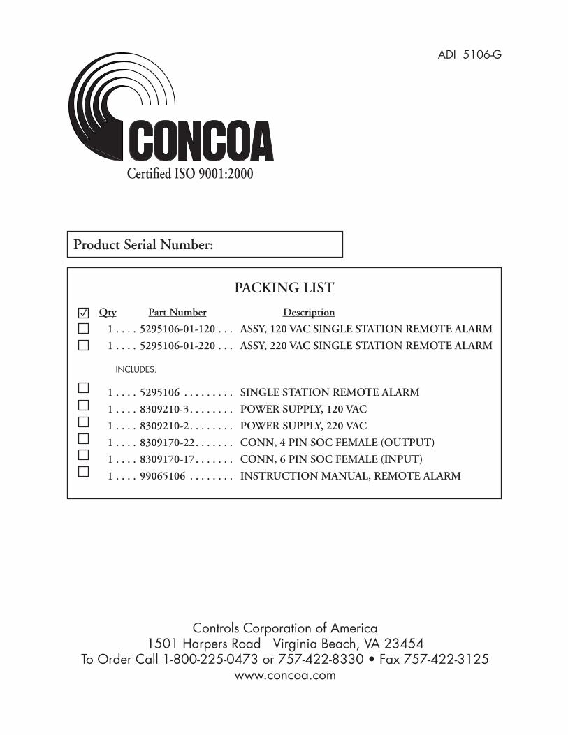
PACKING LIST
Qty Part Number Description
1 . . . . 5295106-01-120 . . . ASSY, 120 VAC SINGLE STATION REMOTE ALARM
1 . . . . 5295106-01-220 . . . ASSY, 220 VAC SINGLE STATION REMOTE ALARM
INCLUDES:
1 . . . . 5295106 . . . . . . . . . SINGLE STATION REMOTE ALARM
1 . . . . 8309210-3. . . . . . . . POWER SUPPLY, 120 VAC
1 . . . . 8309210-2. . . . . . . . POWER SUPPLY, 220 VAC
1 . . . . 8309170-22. . . . . . . CONN, 4 PIN SOC FEMALE (OUTPUT)
1 . . . . 8309170-17. . . . . . . CONN, 6 PIN SOC FEMALE (INPUT)
1 . . . . 99065106 . . . . . . . . INSTRUCTION MANUAL, REMOTE ALARM
Product Serial Number:
ADI 5106-G
Certified ISO 9001:2000
Controls Corporation of America1501 Harpers Road Virginia Beach, VA 23454
To Order Call 1-800-225-0473 or 757-422-8330 • Fax 757-422-3125www.concoa.com