Embed Size (px)
Citation preview
030-1307
6 Mount and align control. Install wallplate (purchased separately).
7 Turn power on.
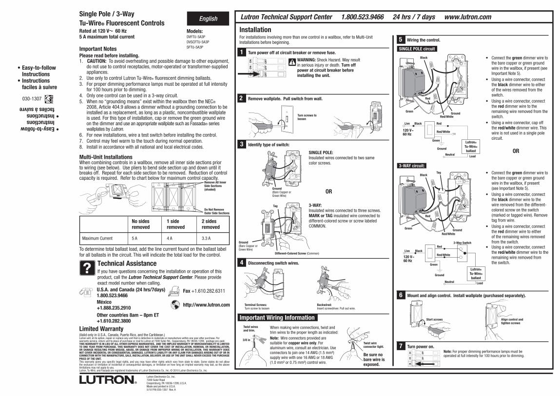
5 Wiring the control.
• Connectthegreendimmerwiretothebarecopperorgreengroundwireinthewallbox,ifpresent(seeImportantNote5).
• Usingawireconnector,connecttheblackdimmerwiretoeitherofthewiresremovedfromtheswitch.
• Usingawireconnector,connectthereddimmerwiretotheremainingwireremovedfromtheswitch.
• Usingawireconnector,capoffthered/whitedimmerwire.Thiswireisnotusedinasinglepolecircuit.
• Connectthegreendimmerwiretothebarecopperorgreengroundwireinthewallbox,ifpresent
(seeImportantNote5).• Usingawireconnector,connect
theblackdimmerwiretothewireremovedfromthedifferent-coloredscrewontheswitch(markedortaggedwire).Removetagfromwire.
• Usingawireconnector,connectthereddimmerwiretoeitheroftheremainingwiresremovedfromtheswitch.
• Usingawireconnector,connectthered/whitedimmerwiretotheremainingwireremovedfrom
theswitch.
InstallationForinstallationsinvolvingmorethanonecontrolinawallbox,refertoMulti-UnitInstallationsbeforebeginning.
1 Turn power off at circuit breaker or remove fuse.
2 Remove wallplate. Pull switch from wall.
3 Identify type of switch:
4 Disconnecting switch wires.
LutronElectronicsCo.,Inc.7200SuterRoadCoopersburg,PA18036-1299,U.S.A.MadeandprintedinU.S.A.5/10P/N030-1307Rev.A
Single Pole / 3-WayTu-Wire® Fluorescent ControlsRated at 120 V 60 Hz5 A maximum total current
Important NotesPlease read before installing.1. CAUTION:Toavoidoverheatingandpossibledamagetootherequipment,
donotusetocontrolreceptacles,motor-operatedortransformer-suppliedappliances.
2. UseonlytocontrolLutronTu-Wire®fluorescentdimmingballasts.3. Forproperdimmingperformancelampsmustbeoperatedatfullintensity
for100hourspriortodimming.4. Onlyonecontrolcanbeusedina3-waycircuit.5. Whenno“groundingmeans”existwithinthewallboxthentheNEC®
2008,Article404.9allowsadimmerwithoutagroundingconnectiontobeinstalledasareplacement,aslongasaplastic,noncombustiblewallplateisused.Forthistypeofinstallation,caporremovethegreengroundwireonthedimmeranduseanappropriatewallplatesuchasFassada®serieswallplatesbyLutron.
6. Fornewinstallations,wireatestswitchbeforeinstallingthecontrol.7. Controlmayfeelwarmtothetouchduringnormaloperation.8. Installinaccordancewithallnationalandlocalelectricalcodes.
Multi-Unit InstallationsWhencombiningcontrolsinawallbox,removeallinnersidesectionspriortowiring(seebelow).Useplierstobendsidesectionupanddownuntilitbreaksoff.Repeatforeachsidesectiontoberemoved.Reductionofcontrolcapacityisrequired.Refertochartbelowformaximumcontrolcapacity.
Black
Red
GroundRed/White
Green
OR
Turn screws to loosen
Ground(BareCopperorGreenWire)
Different-Colored Screw(Common)
Tag 3-WAY:Insulatedwiresconnectedtothreescrews.MARK or TAGinsulatedwireconnectedtodifferent-coloredscreworscrewlabeledCOMMON.
Ground(BareCopperorGreenWIre)
SINGLE POLE:Insulatedwiresconnectedtotwosamecolorscrews.
OR
Backwired:Insertscrewdriver.Pulloutwire.
Terminal Screws: Turnscrewtoloosen
No sides 1 side 2 sides removed removed removed
MaximumCurrent 5A 4A 3.3A Todeterminetotalballastload,addthelinecurrentfoundontheballastlabelforallballastsinthecircuit.Thiswillindicatethetotalloadforthecontrol.
Whenmakingwireconnections,twistandtrimwirestotheproperlengthasindicated:Note:Wireconnectorsprovidedaresuitableforcopper wire only.Foraluminumwire,consultanelectrician.Useconnectorstojoinone14AWG(1.5mm²)supplywirewithone16AWGor18AWG(1.0mm²or0.75mm²)controlwire.
Twist wire connector tight.
Be sure no bare wire is exposed.
3/8 in
Twist wiresand trim.
Lutron®
Tu-Wire®ballast
Live BlackRed/White
Red
Green
Neutral Load
3-Way Switch
120 V~ 60 Hz
Ground
Lutron®
Tu-Wire®ballast
Live
LoadNeutral
Black Red
Red/White
Green
Ground
120 V~ 60 Hz
Limited Warranty(ValidonlyinU.S.A.,Canada,PuertoRico,andtheCaribbean.)Lutronwill,atitsoption,repairorreplaceanyunitthatisdefectiveinmaterialsormanufacturewithinoneyearafterpurchase.Forwarrantyservice,returnunittoplaceofpurchaseormailtoLutronat7200SuterRd.,Coopersburg,PA18036-1299,postagepre-paid.THIS WARRANTY IS IN LIEU OF ALL OTHER ExPRESS WARRANTIES, AND THE IMPLIED WARRANTY OF MERCHANTABILITY IS LIMITED TO ONE YEAR FROM PURCHASE. THIS WARRANTY DOES NOT COVER THE COST OF INSTALLATION, REMOVAL OR REINSTALLATION, OR DAMAGE RESULTING FROM MISUSE, ABUSE, OR DAMAGE FROM IMPROPER WIRING OR INSTALLATION. THIS WARRANTY DOES NOT COVER INCIDENTAL OR CONSEqUENTIAL DAMAGES. LUTRON’S LIABILITY ON ANY CLAIM FOR DAMAGES ARISING OUT OF OR IN CONNECTION WITH THE MANUFACTURE, SALE, INSTALLATION, DELIVERY, OR USE OF THE UNIT SHALL NEVER ExCEED THE PURCHASE PRICE OF THE UNIT.Thiswarrantygives you specific legal rights, and youmayhaveother rightswhich vary fromstate to state.Somestatesdonot allowtheexclusionorlimitationof incidentalorconsequentialdamages,or limitationonhowlonganimpliedwarrantymaylast,sotheabovelimitationsmaynotapplytoyou.Lutron,Tu-Wire,andFassadaareregisteredtrademarksofLutronElectronicsCo.,Inc.©2010LutronElectronicsCo.,Inc.
•Easy-to-followInstructions
•Instructions faciles à suivre
•Easy-to-followInstructions
•Instructions faciles à suivre
Remove All Inner Side Sections (shaded)
Do Not Remove Outer Side Sections
Start screws Align control and tighten screws
Note: Forproperdimmingperformancelampsmustbeoperatedatfullintensityfor100hourspriortodimming.
ON OFF
ON OFF
ON OFF
WARNING:ShockHazard.Mayresultinseriousinjuryordeath.Turn off power at circuit breaker before installing the unit.
SINGLE POLE circuit
Black
Red
Green
Tag
GroundRed/White
3-WAY circuit:
English
Important Wiring Information
Models:DVFTU-5A3PDVSCFTU-5A3PSFTU-5A3P
Technical AssistanceIfyouhavequestionsconcerningtheinstallationoroperationofthisproduct,calltheLutron Technical Support Center.Pleaseprovideexactmodelnumberwhencalling.U.S.A. and Canada (24 hrs/7days) 1.800.523.9466 México +1.888.235.2910Other countries 8am – 8pm ET +1.610.282.3800
Fax+1.610.282.6311
http://www.lutron.com
Lutron Technical Support Center 1.800.523.9466 24 hrs / 7 days www.lutron.com

Informations importantes sur le raccordement
5 Raccordement du gradateur.
• Raccorderlefilvertdugradateuraufildecuivredénudéouaufilvertdemiseàlaterresituédanslaboîtemurale(voirRemarqueImportante5).
• Àl’aided’unconnecteur,raccorderlefilnoirdugradateuràl’undesfilsretirésdel’interrupteur.
• Àl’aided’unconnecteur,raccorderlefilrougedugradateuràlefilrestantretirédel’interrupteur.
• Àl’aided’unconnecteur,recouvrirlefilrouge/blancdugradateur.Cefiln’estpasutilisédansuncircuitUNIPOLAIRE.
• Raccorderlefilvertdugradateuraufildecuivredénudéouaufilvertdemiseàlaterresituédanslaboîtemurale(voirRemarqueImportante5).
• Àl’aided’unconnecteur,raccorderlefilnoirdugradateuràlefilretirédelavisdecouleurdifférentedel’interrupteur(marquéouétiqueté).Enleverl’étiquettedufillibellé.
• Àl’aided’unconnecteur,raccorderlefilrougedugradateuràl’undesfilsrestantretirédel’interrupteur.
• Àl’aided’unconnecteur,raccorderlefilrouge/blancdugradateuràlefilrestantretiré
del’interrupteur.
6 Montage et alignement du gradateur. Montage de la plaque murale (achetée séparément).
7 Rallumer l'alimentation électrique en circuit.
InstallationEncasd’installationdeplusieurscommandesdansuneboîteélectrique,consulterlasectionsurlemontagemultipleavantdecommencerl’installation.
1 Couper l’alimentation électrique au disjoncteur ou à la boîte à fusibles.
2 Enlever la plaque murale. Dégager l'interrupteur du mur.
3 Vérifier le type d'interrupteur.
4 Déconnecter les fils de l'interrupteur.
Gradateur unipolaire / 3 voies Tu-WireTM pour éclairage fluorescentPuissance nominale 120 V 60 Hz courant total maximum 5 A
Remarques importantesVeuiller lire avant de procéder à l’Installation.1. ATTENTION:Pouréviterdesurchaufferetd’endommagerleproduitoud’autreséquipements,nepas
installerdanslebutdecontrôleruneprisedecourant,unappareilàmoteurouunappareiléquipédesonpropretransformateur.
2. UtiliserseulementpourcontrolerlesballastsTu-WireTMLutronàalimentationvariablepourfluorescent.3. Pourunfonctionnementcorrectdugradateur,leslampesdoiventfonctionneràpleineintensitépendant100
heuresavantdepouvoirlesatténuer.4. Nepasutiliserdeuxgradateurssurunmêmecircuit3-voies5. En cas d’absence de mise à la terre dans la boîte murale, le code NEC® 2008, Article 404.9 permet
l’installation d’un gradateur sans connexion à la terre en remplacement, pourvu qu’une plaque murale en plastique non combustible soit utilisée. Pour ce genre d’installation, couvrir ou retirer le fil de terre vert du gradateur et employer une plaque murale adéquate, par exemple les plaques FassadaTM de Lutron.
6. S’ils’agitd’unenouvelleinstallation,installeruninterrupteurd’essaiavantd’installerlegradateur.7. Legradateurpeutparfoisêtrechaudautoucherlorsdesonfonctionnementnormal.8. Installerconformémentauxnormesducodecanadienetdescodeslocauxdel’électricité.
Montage multipleEncasd’installationdeplusieurscommandesdansuneboîteélectrique,touteslessectionslatéralesintérieuresdoiventêtreenlevéesavantleraccordementdesfils(voirleschémaci-dessous).Lacapacitédoitégalementêtreréduite.Voirletableauci-dessous.
RACCORDEMENT UNIPOLAIRE:Lesfilsisoléssontraccordésàdeuxvisdemêmecouleur.
RACCORDEMENT 3-VOIES:Lesfilsisoléssontraccordésàtroisvis.MARQUERouÉTIQUETERlefilisoléraccordéàunevisdecouleurdifférenteouvisétiquetée“COMMON”(SOUSTENSION).
OU
Dévisser les vis.
Fils au verso: Inséreruntournevis.Tirerlefil.
Bornes de raccordement: dévisserlesvis.
OU
Remarque:Lesconnecteursfournissontconçuspourdes fils de cuivre seulement.Pourdesfilsenaluminium,consulterunélectricien.Utiliserlesconnecteurspourraccorderunfild'alimentationdecalibre1,5mm²(14AWG)àunfildugradateurdecalibre1,0mm²ou0,75mm²(16AWGor18AWG).
Pourraccorderlesfils,tordreetdénudertouslesfilsàlalongueurindiquée:
Mise à la terre(filencuivredénudéoufilvert)
Vis de Couleur différente (Soustension)
Mise à la terre(filencuivredénudéoufilvert)
Etiquette
Note: Pourunfonctionnementcorrectdugradateur,leslampesdoiventfonctionneràpleineintensitépendant100heuresavantdepouvoirlesatténuer.
Aucune section Une section Deux sections enlevée enlevée enleveés
Courantmaximum 5A 4A 3,3A
Pourdeterminerlachargetotaleequivalenteauxballasts,additionnerlesdifférentscourantsd'entréementionnéssurlesétiquettesdesballastsducircuit.Celaindiqueralachargetotalepourlecontrôle.
LutronElectronicsCo.,Inc.7200SuterRoadCoopersburg,PA18036-1299,U.S.A.FabriquéetimpriméauxÉ.-U.5/10P/N030-1307Rev.A
Bien visser les connecteurs.
S'assurer qu'aucun fil dénudé ne soit exposé.
10 mm
Tordre et denuder les fils.
Lutron®
Tu-Wire®ballast
Fil de mise à la terre
Noir
Rouge
Rouge/Blanc
Fil sous tension
Interrupteur 3-voies
Fil vert
Neutre Charge
120 V~ 60 Hz
Lutron®
Tu-Wire®ballast
Fil sous tension
Fil de mise à la terre
Charge
Rouge/Blanc
Fil vert
Neutre
120 V~ 60 Hz
Noir Rouge
Fil vert Fil de mise à la terre
Rouge
Rouge/Blanc
Noir
Etiquette
Rouge/Blanc
Fil de mise à la terre
Fil vert
Noir
Rouge
Garantie limitée(Valide seulement aux États-Unis, Canada, Puerto Rico et Caraïbes.)Lutron,àsonchoix,répareraouremplaceratouteunitéprésentantdesdéfautsdematériauxoudemain-d’œuvrependantuneduréedeun(1)anàcompterdeladated’achat.Pourleservicesousgarantie,retournerl’unitéchezledétaillantoul’envoyerparlapostedansuncolisaffranchiàl’adressesuivante:Lutron,7200SuterRd.,Coopersburg,PA18036-1299.LA PRÉSENTE GARANTIE REMPLACE TOUTE AUTRE GARANTIE ExPRESSE, ET LA GARANTIE IMPLICITE DE qUALITÉ MARCHANDE SE LIMITE À UN AN À COMPTER DE LA DATE D’ACHAT. LA PRÉSENTE GARANTIE NE COUVRE PAS LES COÛTS D’INSTALLATION, DE DÉPOSE OU DE RÉINSTALLATION OU LES DOMMAGES RÉSULTANT D’UN MAUVAIS USAGE OU D’UN USAGE ABUSIF, NI LES DOMMAGES RÉSULTANT D’UNE MAUVAISE INSTALLATION OU D’UN RACCORDEMENT INADÉqUAT DES FILS. LA PRÉSENTE GARANTIE NE COUVRE PAS LES DOMMAGES INDIRECTS OU CONSÉCUTIFS. LA RESPONSABILITÉ DE LUTRON CONCERNANT TOUTE RÉCLAMATION POUR DOMMAGES DÉCOULANT DE (OU RELIÉS À) LA FABRICATION, LA VENTE, L’INSTALLATION, LA LIVRAISON OU L’UTILISATION DE L’UNITÉ NE POURRA EN AUCUN CAS DÉPASSER LE PRIx D’ACHAT DE L’UNITÉ.Laprésentegarantieaccordedesdroitslégauxprécis,etcertainsautresdroitsvariantselonl’étatoulaprovincederésidence.Certainsétatsouprovincesnepermettentpasl’exclusionoularestrictiondesdommagesindirectsouconsécutifs,oul’impositiond’unelimitedetempssurlagarantieimplicite.Lesrestrictionsmentionnéesci-dessuspourraientdoncnepass’appliquer.Lutronestunemarquedéposée.Tu-WireetFassadasontdesmarquesdéposéesdeLutronElectronicsCo.,Inc©2010LutronElectronicsCo.,Inc.
ON OFF
ON OFF
ON OFF
Pour tout montage multiple, enlever toutes les sections latérales intérieures (surfaces ombrées).
Ne pas enlever les sections latérales extérieures.
Pour enlever les sections latérales, plier et replier les sections soigneusement à l’aide des pinces jusqu’à ce que les côtés se séparent.
Bien visser les vis en place. Aligner le gradateur.
ADVERTISSEMENT:Risqued’électrocution.Peutcauserledécèsdelapersonneoudegraveslésions.Couper le courant au disjoncteur avant de procéder à l’installation de l’unité.
Circuit UNIPOLAIRE
Circuit 3-VOIES
Français
Assistance TechniqueEncasdequestionreliéeàl’installationouaufonctionnementdeceproduit,appelerle Centre de soutien technique Lutron.Lenumérodemodèleexactestrequisaumomentdel’appel.
U.S.A. et Canada (24h sur 24 / 7jrs sur 7) 1.800.523.9466México +1.888.235.2910 Autres pays : 8h – 20h, heure de l’Est +1.610.282.3800
Télécopieur +1.610.282.6311
http://www.lutron.com
Centre de Support Technique Lutron 1.800.523.9466 24 h / 7 jours www.lutron.com
Modèles :DVFTU-5A3PDVSCFTU-5A3PSFTU-5A3P