Embed Size (px)
Citation preview

PRZEGLĄD ELEKTROTECHNICZNY (Electrical Review), ISSN 0033-2097, R. 88 NR 1a/2012 81
Marcin PARCHOMIUK
Electrotechnical Institute, Department of Power Converters, Warsaw
Single phase voltage converter for traction applications – simulation and investigation
Abstract. Single phase voltage converter structure with isolation transformer for applications in traction vehicles is presented. This paper shows simulation model of this type of converter and transformer model with modern magnetic material in OrCAD-PSpice simulation program. Two PWM control techniques are compared in order to eliminate voltage and current oscillations in primary winding of the transformer, decrease large peaks of current, decrease large system loss and improve system efficiency. Author shows a comparison of the PSpice simulation results with the real results. Streszczenie. W artykule przedstawiono strukturę jednofazowego przekształtnika napięcia z izolacją transformatorową dla zastosowań w pojazdach trakcyjnych. Zaprezentowano modele symulacyjne przekształtnika oraz transformatora z nowoczesnych materiałów magnetycznych, opracowane w programie OrCAD-PSpice. Porównano dwie metody sterowania przekształtnikiem, pozwalające na eliminację oscylacji w uzwojeniu pierwotnym transformatora, zmniejszenie przeregulowań prądowych oraz strat, i zwiększenie sprawności układu. Porównano wyniki symulacyjne z wynikami pracy przekształtnika rzeczywistego. (Napięciowy przekształtnik jednofazowy do aplikacji trakcyjnych – symulacja i badania) Keywords: traction, DC/DC, converter, transformer. Słowa kluczowe: trakcja, DC/DC, przekształtnik, transformator. Abstract
A progress in modern semiconductors influences on dynamic power converters development. These devices operate at higher frequencies and have to supply increasingly growing power needs. In addition the latest magnetic materials allow the construction of magnetic elements with high efficiency and small size. But at the stage of building and running power converter there are weaknesses in proper operation of such systems despite the fact we use technologically advanced components. For this reason the paper discusses the structure of DC-DC converter with isolation transformer for supplying the needs of traction vehicles. Description of the converter
Selected simulation aspects were performed on a single phase full bridge voltage inverter with isolation transformer (Fig. 1) [1]. This is the structure, which has become an essential solution for high power traction converters in recent years. According to the standards traction devices are supplied with voltage of 600V (+30%-25%) [2]. The task of such a converter is to convert traction voltage to galvanically separated voltage of a certain value. According to the needs of traction vehicles, the most popular voltage source is 24V DC. In this respect simulation model presents this level of output voltage with nominal output power 10kW (output current approximately Iout = 400A).
For the assumed configuration there was a power converter used. It was operating at frequency of 16kHz, which allows to reduce the size of passive components, and thus reduce the dimensions of the device.
High frequency converter brings certain difficulties. With the increase of the frequency it results additional power losses in the windings of the transformer (the presence of the skin effect), transistors and core loss (hysteresis and eddy currents). In addition in this type of converter there are more important oscillations of the voltage and high current pulses in primary winding of transformer during the transistor switching.
In order to understand the phenomena occurring in this type of converters, a simulation model was created in OrCAD-Pspice program. Simulation model of the converter
Simulation model of DC-DC full bridge converter with isolation transformer was designed in Orcad-PSpice
program (Fig. 2). It consists of: regulated voltage source, input low pass filter, voltage inverter, isolation transformer, rectifier, output low pass filter and load. To control the transistors epoly function was used. This function can operate as voltage source control. Voltage inverter was controlled using pulse width modulation PWM techniques. Two methods were used and compared: (traditional) symmetrical PWM and Phase Shifted PWM PS-PWM (see results). Control pulses of the transistor were generated alternately with a dead time taken into account.
To obtain simulation model parameters as close as possible to the real system, producers models of transistors and diodes were used. Very important issue is to use real transformer model with the appropriate identification of the core. This allows to observe and understand phenomena in the work of this type of converter.
Fig.1. Model of single phase full bridge voltage inverter– selected structure for simulation studies. Simulation model of the transformer An important issue to research and analyze a selected structure of the converter is to prepare core model of non-linear isolation transformer, with real magnetizing characteristic of material. OrCAD-PSpice is equipped with special tool to create this kind of model based on self-defined hysteresis loop. This program allows to introduce some parameters of the core, e.g. dimensions, initial permeability, hysteresis loop points. This is particularly important for modeling nonlinear magnetization characteristics of magnetic circuits. Currently there are many different magnetic materials available on the market (e.g. nanocrystalline or amorphous materials). These materials are suitable for many applications, have different shape, parameters and magnetic characteristics [3][4].
82 PRZEGLĄD ELEKTROTECHNICZNY (Electrical Review), ISSN 0033-2097, R. 88 NR 1a/2012
Fig. 2. Simulation model of a single phase full bridge voltage inverter in OrCad-PSpice program
Nanocrystalline core model of Vitroperm 500F (Vacuumschmeltze product) was created (material parameters in Table 1). Fig. 3 shows the view of modeled magnetization characteristics of this material in the Orcad-PSpice model editor. In order to achieve the best accuracy of the material, hysteresis loop was first measured with an oscilloscope using Dirac impulse response technique and then introduced to a model editor. To create a library of a core, the following parameters were used: Ae = 8,22 cm2 (cross section of the core), le = 36,1cm (length of a path in the magnetic core), µ0 = 30000 – initial permeability, toroidal shape of the core. Table1. Magnetic core parameters of Vitroperm 500F
Nr Parameters
Type Values 1 Tape width 25 µm 2 Flux den sity 1,2 T 3 Permeability 10000-150000 4 Resistivity 115 µΩcm 5 Magnetostriction 1e-8 – 1e-6 6 Core loss 80[W/kg] for 100kHz, B=0,3T 7 Curie temperature 600°C 8 Operation temperature 120-150°C
Fig. 3. Magnetization characteristics of nanocrystalline core of Vitroperm 500f. Function B=f(H) were modeled in the Orcad-PSpice model editor (10kGauss=1T, 1Oe≈80A/m).
Core model was introduced to the nonlinear transformer model in Orcad-PSpice program. The nonlinear model is based on a theory which has been developed by D. Jiles and D Atherton in the eighties of the last century [5] (JA Model). The following transformer parameters were taken: Rp1 = 150 mΩ (primary winding resistance), Rp2 = 50 mΩ (secondary winding resistance), N1 = 16 (number of turns of primary winding), N2 = 1 (number of turns of secondary winding). Transformer model with actual magnetization characteristics of magnetic nanocrystalline material was
created. It was used in the studies on simulation model of DC-DC converter.
The results of the converter operation Fig. 4 presents the results of the operation of the system
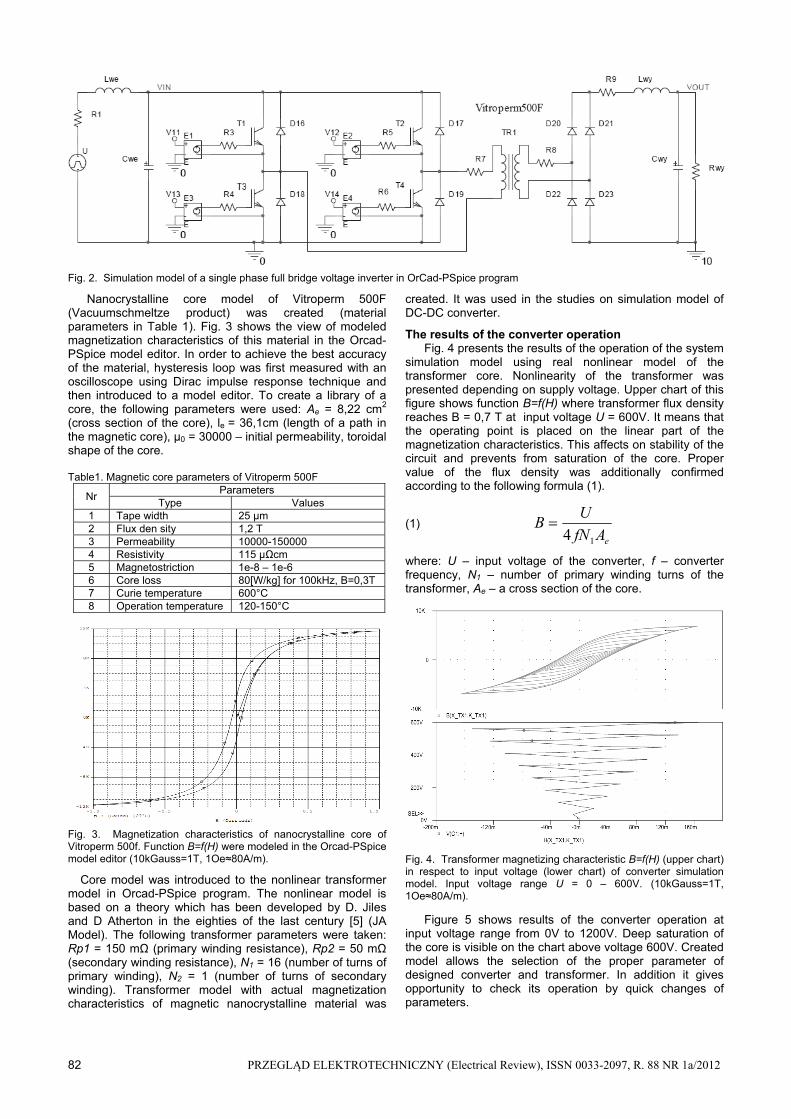
simulation model using real nonlinear model of the transformer core. Nonlinearity of the transformer was presented depending on supply voltage. Upper chart of this figure shows function B=f(H) where transformer flux density reaches B = 0,7 T at input voltage U = 600V. It means that the operating point is placed on the linear part of the magnetization characteristics. This affects on stability of the circuit and prevents from saturation of the core. Proper value of the flux density was additionally confirmed according to the following formula (1).
(1) eAfN
UB
14
where: U – input voltage of the converter, f – converter frequency, N1 – number of primary winding turns of the transformer, Ae – a cross section of the core.
Fig. 4. Transformer magnetizing characteristic B=f(H) (upper chart) in respect to input voltage (lower chart) of converter simulation model. Input voltage range U = 0 – 600V. (10kGauss=1T, 1Oe≈80A/m).
Figure 5 shows results of the converter operation at input voltage range from 0V to 1200V. Deep saturation of the core is visible on the chart above voltage 600V. Created model allows the selection of the proper parameter of designed converter and transformer. In addition it gives opportunity to check its operation by quick changes of parameters.

PRZEGLĄD ELEKTROTECHNICZNY (Electrical Review), ISSN 0033-2097, R. 88 NR 1a/2012 83
Fig. 5. Transformer magnetizing characteristic B=f(H) (upper chart) in respect to input voltage (lower chart) of converter simulation model. Input voltage range U = 0 – 1200V. (10kGauss=1T, 1Oe≈80A/m).
This article highlights the operation of the converter at idle and under load, for various pulse width control. The following figures show the moment of transistor switching, where dangerous oscillation of the primary voltage of the transformer appear. It also causes the occurrence of instantaneous high current peaks and force to use power semiconductors elements for higher values (eg. transistors of the voltage inverter). These oscillations appear on secondary side of the transformer and have negative influence for output circuits operation, which reveals in higher power losses and elements for higher voltage and current class.
In real working conditions of the converter it is difficult to determine, whether the measured waveforms contain such a shape or whether it is a result of electromagnetic signal distortion derived from rapid changes in voltage and current in the circuit. Even highly specialized measuring equipment are not always able to determine this. Measurement should be made at least with two different measurement methods or systems. By measuring and comparing the results with the results of simulation there can be carried out a comparative analyses of the phenomenon and delineated.
By comparing the simulation results with those of the real system (Fig. 6 and Fig.9) the cause of the oscillation voltage on the primary winding of the transformer was found. Leakage inductance of the transformer together with the transistor capacitance of the inverter causes signal oscillations. According to the Thomson formula (2) describing the resonant frequency of LC circuit, it appeared in simulation model as well as in real one, natural frequency of the circuit f = 850 kHz.
(2) LC
f
2
1
2
Oscillations (Fig.6 and Fig.9) in the system arise from the reactive energy collected in the electromagnetic circuit [1] [6]. The amplitude of those oscillations depend on current flowing through the magnetic circuit (the higher current values the more significant oscillations became) and squareness ratio of magnetic material hysteresis loop. On the one hand, the application of magnetic material with a rectangular shaped hysteresis loop, have favorable effect on the work of the converter, but result in the presence of small oscillations of voltage and current. On the other hand, the surface area of the hysteresis loop is proportional to the energy losses in the core. In addition, materials with high squareness ratio when used in pulse converters are more likely to core saturation than those with tilted magnetization
characteristics. Designers of power electronics devices often use air gaps in order to tilt the magnetization characteristics in transformers and chokes.
Fig. 6. Voltage oscillations in primary winding of the transformer for different current values Io1>Io2>Io3.
The occurrence of these phenomena indicates that at the design stage of the power converter designer should apply a compromise in choosing the right magnetic material, as well as to adopt an adequate reserve in the selection of semiconductor elements, because of high current. This approach have effects in better efficiency of the system and higher capability.
One of the methods to eliminate oscillations in the primary winding circuit of the transformer is phase shifted pulse width modulation PS–PWM (Fig. 7), which were investigated in literature [6][7]. This method was compared with traditional symmetrical pulse width modulation (Fig. 8). The main difference is that gate signals of the transistors are phase shifted in diagonal of H-Bridge (Fig. 7) e.g. gate signals of T1 and T3 are shifted in respect to T2 and T4.This allows to discharge energy stored in the magnetic circuit and prevent from oscillations of voltage and current. Comparison results of two control techniques in the simulation model are shown (Fig.9). There are voltages and currents of the transformer primary winding presented. Charts are placed in two column for better comparison.
On the left column there are simulation results with classical PWM technique. The right column presents results with PS-PWM control. These two control techniques are shown and compared in respect to a different pulse width. There are oscillations on voltage and current visible when classical PWM control is used due to energy stored in magnetic circuit. When PS-PWM control is used these oscillations disappear because energy in the circuit is discharged. It is possible due to the fact that in this control technique two transistors are always switched on. On the last charts of Fig.9 the real converter (Fig.10) results are placed. They are close to those from simulation model.
Very important issue is compensation of constant component, which is worth mentioning, but due to comprehensiveness of issues not developed in this work. Theoretically, magnetizing current and flux of the transformer should not include a fixed component, which may occur as a result of the lack of symmetry of the control transistors, transistor driver work asymmetry or irregular work of the load. A common cause of the constant component is the difference in switching times of transistors or different voltage drops on transistors. This leads to the occurrence of random faults in the device and its exemptions. One of the methods of constant component compensation is capacitor inclusion to primary winding of the transformer.

84 PRZEGLĄD ELEKTROTECHNICZNY (Electrical Review), ISSN 0033-2097, R. 88 NR 1a/2012
Fig. 7. Phase shifted Pulse Width Modulation PS-PWM technique. DTs – pulse width, Ts – inverter operation period, φ – phase shift.
Fig. 8. Symmetrical Pulse Width Modulation – PWM technique. Where: DTs – pulse width, Ts – inverter operation period.
a)
b)
c)
d)
e)
f)
Figure 9. Voltage and current of the transformer primary winding in the simulation model. Above charts show: a) Phase Shifted PWM (PS-PWM) control with 50% pulse width, b) Symmetrical PWM control with 50% pulse width, c) Phase Shifted PWM (PS-PWM) control with 85% pulse width, d) Symmetrical PWM control with 85% pulse width, e) ) Phase Shifted PWM (PS-PWM) control with 85% pulse width in a real converter (C2 – 500V/div, C3 – 20A/div), f) Symmetrical PWM control with 85% pulse width in a real converter (C1 – 500V/div, C4 – 40A/div)

PRZEGLĄD ELEKTROTECHNICZNY (Electrical Review), ISSN 0033-2097, R. 88 NR 1a/2012 85
Fig. 10. Laboratory model of the real converter. Input voltage 3x400V, nominal output power 10kW, nominal output voltage 24V, up to 20kHz operation.
In many applications, this solution is effective, which is described in the literature. Another way to avoid transformer core saturation is proper design of this magnetic element, consisting of the working set point with large reserve, so as to have ability to work with a small asymmetry. Conclusion
Created simulation models reflecting the best working conditions and the results obtained from research of DC-DC converter allow to explain and understand some of the phenomena. Also allow to carry out impact studies on the parameters of individual elements of the converter operation, which are particularly important when constructing a model of the inverter. Compared to the real system there are no possibilities to change e.g. transistor capacitance, which depends on the structure and technical production process.
Currently available simulation tools such as OrCAD-PSpice or Matlab, allow designers to look carefully at the operation of the converters before they are built. These
tools are complemented by programs to simulate and analyze the distribution of the magnetic field or heat, using the finite element calculations. This is critical for the proper design of magnetic circuits, which are important elements of converter.
Another reason for creating simulation models discussed in this paper is also growing demand for this type of devices in the industry. They are applied not only in urban transport and rail, but also by many companies requiring accurate energy supply with growing demand for power.
REFERENCES [1] J.A.Sabate, V.Vlatkovic, R.B.Ridley, F.C.Lee, B.H.Cho, Design
considerations for high power full-bridge ZVS-PWM converter, Proc. IEEE, APEC ’90, 1990, pp.275-284.
[2] EN50163: 2004 – Railway Applications Standards. Supply voltages of traction systems.
[3] W.Shen, F.Wang, D.Boroyevich, C.Wesley, High-Density Nanocrystalline Core Transformer for High-Frequency Resonant Converter, IEEE Transactions on Industry Applications, vol.40, 2008.
[4] M.Parchomiuk, K.Tomczuk, Projektowanie transformatora impulsowego w programie Matlab–Simulink, Wiadomości Elektrotechnicze, 03/2010.
[5] D.C. Jiles, D.L. Atherton, Theory of ferromagnetic hysteresis, 1986.
[6] H.Bai, Ch.Mi, Eliminate reactive power and increase system efficiency of isolated bidirectional Dual-Active Bridge DC-DC Converters Using Novel Dual-Phase-Sift Control, IEEE Transactions on Power Electronics, VOL.23, 2008.
[7] J.E.Baggio, H.L Hey, H.A.Grundling, H.Pinheiro, J.R.Pinheiro, Isolated Interleaved-Phase-Shift-PWM DC-DC ZVS Converter, IEEE Transactions on Industry Applications, vol. 39, 2003.
Authors: mgr inż. Marcin Parchomiuk, Instytut Elektrotechniki, Zakład Przekształtników Mocy, ul. Pożaryskiego 28, 04-703 Warszawa, e-mail: [email protected]