Embed Size (px)
Citation preview

Single-phase inverter configurable for use on stand-aloneequipment or grid connected
ELETTRONICASANTERNO

Producing energy directly from the sun using the
“photovoltaic effect”, is particularly interesting if we
consider that the quantity of energy reaching the
Earth from the sun every day is far more
than the world’s energy needs.
The photovoltaic modules (made up of many cells which
exploit this “effect”), connected together in series and
in parallel, exposed to enough sun and connected
to a load, can produce direct current electrical energy.
Problems of a technical and economic nature, such as
the production of energy possible only during the day,
the low conversion yield and cost of the cells, and
instability in changing weather conditions,initially
delayed the exploitation of this type of energy.
The continual technological development, however, is
gradually overcoming these limits and today we can find:
modules with a higher yield, a long life (20-25 years)
and at a lower cost, reliable batteries to enable
the accumulation during the day of energy which
can be used during the night, and highly
reliable inverters with high yields.
Advantages and uses of photovoltaic energyThe advantages of photovoltaic energy generation can
besummarised as follows: no noise or pollution, practically
no maintenance for the entire production plant, size of
the plant adjustable to the user’s real needs.
It can be used in both residential and industrial applica-
tions, in stand-alone or grid-connected modes,
and in a myriad of differentcommercial products.
Residential applications include plants to electrify
mountain refuges, rural and urban homes,
pumping stations,street lighting, etc.
Industrial applications, instead, include power for road
signs and railway signals, radio links, repeaters and,
in general, in all sectors of the telecommunications industry.
Popular commercial products include toys, radios,
watches, etc. powered by solar cells,
which are produced every year inenormous quantities.
fromthe

The inverters of the SUNWAY line are static devices with
a 220-230 Vac single-phase output, completely digitally
controlled, and are supplied in two versions:
• S U N WAY - M, in two sizes of 1.8 and 3 kVA, specially
designed to power a load in a stand alone situation or to
provide energy for the network in grid connected mode.
• S U N WAY - M-gc, in three sizes
of 1.8, 2.5 and 3 kW, designed
for grid connected
u s e .
Sunway - M Line
ELETTRONICASANTERNO

•Design and manufacture comply with the requisites of the “Low Voltage Directive” and the “EMC Directive”.
•Compliance with the CE Standards.
•DC/AC conversion using PWM technology and a MOSFETbridge for high efficiency (yield <0.94) and high reliability.
•Toroidal output transformer capable of guaranteeing total insulation between the grid and the
photovoltaic unit/DC side of the inverter.
•Input and output filters for the suppression ofinduced and emitted interference,
both conducted and irradiated.
•Control of the voltage generated (stand alone) or of the output current supplied (grid connected)
through a 16-bit microprocessor which guarantees a sinusoidal form with extremely low distortion.
•Grid-connected operation at cosϕ=1.
•Programming and monitoring through alphanumeric keyboard or PC
(via RS232 serial interface) for monitoring and programming of the machine parameters.
•Remote monitoring through local networkwith CAN-BUS field bus. This makes the
SUNWAY-M inverters universally applicable: both as single devices working autonomously
and as elements of a large plant containing several Sunway inverters, with supervision of the
operation of each of them from a single central point.
•Card for checking the insulation resistance between input and ground (optional).
•Data Logger for main values (optional).
•Analog inputs (3) - optional - for monitoring of plant values such as ambient temperature, insolation, etc.
(2 of the 3 analog inputs can be transformed into digital inputs - optional).
•A particularly strong metal container suitable for open-air applications.IP 65 protection (1.8-2.5 kVA); IP 55 (3 kVA).
•Connection in three-phase configuration with special electromechanical adapter (only in griconnected mode).
Main characteristics of the Sunway-M and Sunway-M-gc inverters

This inverter is designed for both types of application. The choi-
ce of one or the other is easily made using the keyboard provi-
ded (operation protected by a password) and adjusting the ter-
minal connections.
The double function of the inverter (see block diagram) is
particularly interesting for plants which were originally desi-
gned to work in stand-alone mode and are later reached and
supplied by the electrical grid. In this case, the change in the
configuration allows the photovoltaic modules in the plant to
be still used without the burden of supplementary costs.
The use of carefully selected components, the notable quan-
tity of warning and measuring information provided on the
display (in Italian and in English), the protections incorpora-
ted for both inputs and outputs and a particularly strong con-
tainer designed for applications in the open air, make the
SUNWAY-M inverters extremely reliable and suited to the
uses for which they were designed and manufactured.
S u n w a y - M
ELETTRONICASANTERNO

In stand-alone mode, the inverter is powered by a source of voltage such as a battery.
The purpose of the converter in this case is to generate a sinusoidal voltage of 220-230Vac - 50 Hz.
In order to reduce losses, the inverter goes into “stand-by” when the user has no need for energy.
The insertion of a load causes the inverter to intervene immediately,
and in a fraction of a second the output is adjusted to the nominal value.
SUNWAY-M can also supervise the battery voltage. In fact, if its voltage falls below a certain value the inverter turns
itself off, in order to prevent it being damaged. In the same way, if the battery voltage is too high the inverter comes on,
even without a load, to dissipate the excess energy.
Thanks to the monitoring of the battery by the inverter, in the case
of a flat battery an emergency generator can be turned
on via a clean relay contact to charge the battery, turning
it off again when the battery reaches its maximum voltage.
The on-off commands of the back-up generator are
managed automatically by the SUNWAY-M inverter’s internal
intelligence to guarantee the lowest possible consumption of fuel.
The continual monitoring of the output values, finally,
guarantees optimal protection from overloads and short circuits.
Sunway-M in stand-alone mode
Main Features of the Sunway-M Inverter
in Stand-alone Mode.
• Protection against overloading.
• Load sensor to minimise unnecessary consumption.
• Control of supply voltage to prevent excessive discharge of the batteries.
• Control of a possible emergency back-up generator.
Three-phase and single-phase applications.The Sunway-M-gc and the Sunway-M (in grid-connected mode) can be applied in three-phase con-
nections to make a three-phase generator. The protection devices of each converter guarantee the
safety of the plant in this configuration too.
To enable each machine to perform its MPPT function, the single photovoltaic fields must be separate
and independent.
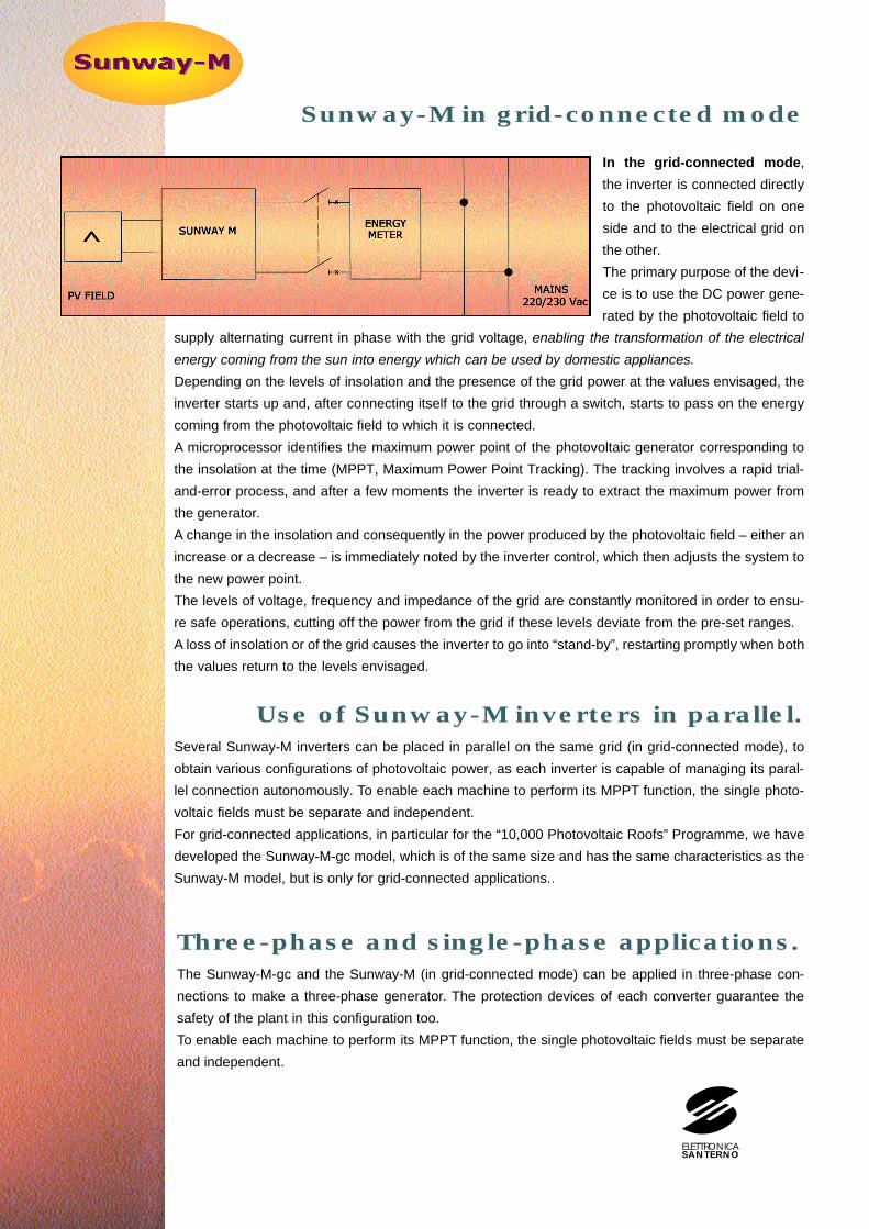
In the grid-connected mode,
the inverter is connected directly
to the photovoltaic field on one
side and to the electrical grid on
the other.
The primary purpose of the devi-
ce is to use the DC power gene-
rated by the photovoltaic field to
supply alternating current in phase with the grid voltage, enabling the transformation of the electrical
energy coming from the sun into energy which can be used by domestic appliances.
Depending on the levels of insolation and the presence of the grid power at the values envisaged, the
inverter starts up and, after connecting itself to the grid through a switch, starts to pass on the energy
coming from the photovoltaic field to which it is connected.
A microprocessor identifies the maximum power point of the photovoltaic generator corresponding to
the insolation at the time (MPPT, Maximum Power Point Tracking). The tracking involves a rapid trial-
and-error process, and after a few moments the inverter is ready to extract the maximum power from
the generator.
A change in the insolation and consequently in the power produced by the photovoltaic field – either an
increase or a decrease – is immediately noted by the inverter control, which then adjusts the system to
the new power point.
The levels of voltage, frequency and impedance of the grid are constantly monitored in order to ensu-
re safe operations, cutting off the power from the grid if these levels deviate from the pre-set ranges.
A loss of insolation or of the grid causes the inverter to go into “stand-by”, restarting promptly when both
the values return to the levels envisaged.
Use of Sunway-M inverters in parallel.Several Sunway-M inverters can be placed in parallel on the same grid (in grid-connected mode), to
obtain various configurations of photovoltaic power, as each inverter is capable of managing its paral-
lel connection autonomously. To enable each machine to perform its MPPT function, the single photo-
voltaic fields must be separate and independent.
For grid-connected applications, in particular for the “10,000 Photovoltaic Roofs” Programme, we have
developed the Sunway-M-gc model, which is of the same size and has the same characteristics as the
Sunway-M model, but is only for grid-connected applications..
Sunway-M in grid-connected mode
ELETTRONICASANTERNO

Electromagnetic Compatibility Directive
(89/336/CEE and later modifications
92/31/CEE, 93/68/CEE and 93/97/CEE)
Immunity:• Test for immunity to electrostatic discharges in accordance with EN61000_4_2.
Levels:6kV for discharge on contact8kV for discharge in air
• Test for immunity to fast transients in accordance with EN61000_4_4.Levels: 2kV/5Khz PV field side and grid side
2V/5Khz serial RS232• Test for immunity to impulses in accordance with EN61000_4_5.
Levels:1kV +terminal/-terminal PV field side2kV +terminal/ground PV field side2kV -terminal/ground PV field side1kV phase/neutral Grid side2kV phase/ground Grid side2kV neutral/ground Grid side
Conducted emissions:EN55011 group 1 class B
Standards
Via G. Di Vittorio, 3 - 40020 Casalfiumanese - Bo - ItalyTel. +39 0542 687711 - Fax. +39 0542 687722e-mail: [email protected] - http:www. e l e t t r o n i c a s a n t e r n o . i t
Elettronica santerno declina ogni responsabilità per eventuali danni a persone o cose originati da un improprio o errato impiego dei propri prodotti. Il catalogo è soggetto a modifiche senza preavviso.Elettronica Santerno declines all liability for any damage to people or property caused by unsuitable or incorrect use of its products. This catalog is subject to change without prior notice.
Characteristic
Peak power of the photovoltaic generator (kWp)Nominal power (kVA)Nominal input voltage (Vdc)Range of variation of input voltage (Vdc)(1)
Converter operating range (Vdc)(1)
Reactive power supply capacityTransitory overload at 20 °CTransitory overload or output short circuit at 20 °CSupplied current limitation intervention theresoldEfficiency at Vin= Vnom, 20%Pn, Vout=Vnom includingnetwork compling insulation transformer lossesEfficiency at Vin= Vnom, 75%Pn, Vout=Vnom includingnetwork compling insulation transformer lossesPower dissipated in Stop (without impulses at the bridge) (W)Power dissipated without loadNominal output voltage (Vac)
Output frequency (Hz)Frequency stability (%)Supplied network current cosϕVout static stability, for variations in Vin and Iout from 0 tonominal values (%)Maximum transitory variation in Vout for variations in loadof 30% to 100% (%)Delay in the regulation of Vout to come back to 2% of Vnom (ms)Current ripple frequencyTotal distortion of the output voltage waveform for the wholepower rangeTotal distortion of the output voltage waveform for the wholepower rangeInsulation voltage to groundInsulation voltage to groundDegree of protectionNoise at 1 metre in the 16Hz-20KHz rangeCoolingWorking temperatureStorage temperatureRelative humidityDimensions (lxhxd) (mm)Weight (kg)
Sunway M1201,8 kVA
2,31,8120
99-17099-170
Sunway M1203 kW3,83
12099-17099-170
Sunway M1202,5 kW
3,42,5120
99-17099-170
Sunway M1203 kVA
3,83
12099-17099-170
cosϕ ≥0.5125% Pnom for 10 min
150% Pnom for 10 sec150% Inom
≥0,88 (cosϕ=0,8)
≥0,92 (cosϕ=0,8)
≤12≤40
220 ±5% (adjustable)230 ±5% (adjustable)
50 o 60 (programmable)≤0,5
≤2
≤8
≤100 8
≤3%
≥0,9
≥0,93
≤12
220±10% or 380±10% for three-phase connection230±10% or 400±10% for three-phase connection
50 o 60 (programmable)
≥0,99
16
≤3%
1kV a 50 Hz for 60s2,5 kV a 50 Hz for 60s
IP55 (for 3 kVA) / IP65 (for 1,8/2,5 kVA)<55 45
Forced with radiator temperatur > 50°C (per 3kVA) - Natural (for 1,8/2,5kVA)-10÷+45°C-20÷+50°C
95% a 20°C370x520x350
50
Sunway-M Sunway-M Sunway-MgcStand alone Grid connected
Nominal characteristics Sunway - M
Sunway M1201,8 kW
2,31,8120
99-17099-170
C a b i n e tThe inverter is housed in a metal container for wall mountin g, with degree of protection IP55/65.To enable easier handling of the Sunway-M, four accessory handles are available; these can be applied on the sides ofthe equipment during transport and mechanical installation.
(1) Other voltages on request
ELETTRONICASANTERNO