Embed Size (px)
Citation preview

MAY, 2019 HD 124PAGE 1 OF 6
HD FIRE PROTECTPVT. LTD.
SINGLE INTERLOCK, SUPERVISED PREACTION SYSTEM WITH ELECTRIC RELEASE
SIZE 50, 80, 100, 150 & 200 NB
DELUGE VALVE Model H3, UL Listed
CHECK VALVE Model-CH
SPRINKLER ALARM UL Listed (Optional)
RELEASE PANEL UL Listed (Optional)
WATER FLOW UL Listed SWITCH
SOLENOID VALVE 24V DC, UL Listed
AUTOMATIC AIR Oil-less Risermount SUPERVISOR Compressor (Optional)
AIR PRESSURE PMD-1 (Optional) MAINTENANCE DEVICE
MANUAL SYSTEM UL Listed, Butterfly Valve - SHUTOFF VALVE Standard supply. (Gate Valve - Optional)
MAXIMUM WORKING 17.5 Kg./sq.cm. (250 PSI)PRESSURE
SYSTEM END Grooved (Standard supply) CONNECTION Flanged (Optional supply)
APPROVAL UL Listed
TECHNICAL DATA
DESCRIPTIONThe Single Interlock Supervised Preaction System is generally used to protect water sensitive areas such as computer rooms, storage areas, libraries, archives, banks, etc., to avoid water damage due to damaged sprinklers or damaged sprinkler piping. Preaction System is also effectively used to have Pre-alarm of a possible fire condition and allows time to extinguish fire by hand held fire extinguishing equipment, prior to water discharge through sprinkler heads. It uses an automatic sprinkler with supplemental detection system. In the event when fire cannot be extinguished by hand held fire extinguishing equipment, the increase in temperature will open one or more sprinkler heads to discharge water.
In normal condition, preaction system does not contain water in the sprinkler piping. The sprinkler piping contains air pressure for the purpose of supervising its leak tightness. As per NFPA, the preaction system employing more than 20 automatic sprinklers is to have the sprinkler piping automatically supervised.
The electric detection system in single interlock preaction system will respond to a fire faster than the automatic sprinkler. When fire is detected through electric system, the primary water control deluge valve opens, allowing water flow into the sprinkler piping in readiness for possible subsequent opening of one or more sprinklers.
SYSTEM OPERATIONThe Electric Actuated, Supervised Single Interlock Preaction System utilizes automatic sprinklers and an additional electric detection system. Electric detection system utilizes 24V.DC heat detectors or smoke detectors. When one electric detector senses the presence of fire, the releasing control panel activates fire alarm devices and latches solenoid valve in open position. If two detectors are cross zoned, then operation of the two detectors will be required to activate the fire alarm device and latch open the solenoid valve. Opening of solenoid valve will drain the water from deluge valve diaphragm chamber, there by reducing the diaphragm chamber pressure and actuation of the deluge valve, allowing the water flow in the sprinkler system.
The water flow will also produce water pressure in the alarm trim of deluge valve. This may actuate the pressure switch if additionally provided to control the shut down of equipment such as computers or start up of the second alarm devices. The flow of water converts the dry system into the wet system at this stage. The water discharge will start only when one or more automatic sprinkler open due to increase in temperature. In normal condition the integrity of system is automatically supervised by the automatic air supervisory means. Air or nitrogen at 18 PSI (1.26 Bar) pressure is maintained in the sprinkler system up to the downstream of the riser check valve.
The supervisory low alarm switch is set at 6 PSI (0.42 Bar). The decreasing pressure will give trouble annunciation due to the loss of pressure, due to abnormal leakage in the sprinkler system piping as a result of the damaged sprinkler or broken pipeline. This will not open the deluge valve. The air pressure is

MAY, 2019 HD 124PAGE 2 OF 6
HD FIRE PROTECTPVT. LTD.
for supervisory alarm only. The automatic supervisory air supply can be maintained through factory set air compressor. The compressor is compact and can be riser mounted or floor mounted. The supervisory air can be maintained with the tank mounted compressor and air maintenance device.
If continuous plant air supply or regulated Nitrogen source is available, then air maintenance device shall be used to maintain the suprvisory air supply.
The major benefits of this system as compared to the conventional wet/dry pipe sprinkler system are,
a) A fire alarm sounds prior to operation of a sprinkler, which may enable to extinguishing of the fire by hand held means, before operation of any sprinkler head. This can eliminate water damage.
b) Whenever integrity of the piping or sprinkler is disturbed, no water flows, only trouble annunciation alarm signals. This will avoid water damage to valuable property.
c) Early fire alarm is provided by electric detection system, without the delay of water delivery time.
INSTALLATION & COMMISSIONINGThe preaction system valves, panel, indicators must be installed in a readily visible and accessible location. The system valves and accessory shall not be installed in an area having temperature less than 4oC (40oF). Heat tracing to system valve and accessory is not permissible. The system must be installed and operated carefully by a trained person, having good knowledge of equipment. All system piping must be flushed thoroughly before commissioning.
After initial successful tests, an authorized person must be trained to perform inspection, testing and maintenance of the system.
NOTE:
The system may have arrangement of electric detectors in a cross-zoned array. The arrangement will prevent false activation of one detector, causing water to flow into the sprinkler piping. Few approving authorities do not permit cross zoning, hence system designer must design the system as per Local Authority having Jurisdiction. The system to be hydraulically calculated as a wet pipe system.
It is strongly recommended that Detection System must be designed to operate sooner than the automatic sprinkler heads.
RECOMMENDED SEQUENCE OF INSTALLATIONSIn planning the installation, consideration must also be given to the disposal of relatively large quantities of water that may be associated with draining of the system or performing flow test.
1. Install the Deluge Valve on Riser.
2. Install the Riser Check Valve above Deluge Valve as shown in installation drawing.
3. On completion of system piping, install all the trims as per trim drawing. Care must be taken to ensure that Check Valves, Strainers, Valves etc. are installed with the flow arrows in the proper direction.
4. Connect all drain piping as shown in the drawing.
5. All unused opening on valve or trim parts must be plugged.
6. Connect air supply line.
7. Connect all electrical to control panel as per wiring drawing.
8. Make sure that all the nut bolts, fittings are screwed properly.
9. Follow the valve resetting and test procedure.
RESETTING PROCEDUREa. Close the upstream side stop valve of the Deluge Valve.
b. Open drain valves and allow water to drain (if water flow was establish) & close drain valve when water flow has ceased.
c. Check all release devices are closed. Inspect the release devices if system was subject to fire condition.
d. Open the priming line so that the diaphragm chamber reads the system water pressure. Open the manual release station partly to vent the air & then close it.
e. Open the upstream side of stop valve to read the Deluge Valve Inlet water supply pressure. The Deluge Valve is set.
f. Open the air supply line and check the pressure is maintained up to 18 PSI (1.26 Bar) and Control Panel is kept on.
h. Check all the trim parts for possible leak.
INSPECTION AND MAINTENANCEInspection and testing is to be carried out only by an authorized and trained personnel. DO NOT TURN OFF the water supply or close any valve to make repair(s) or test the valve, without placing a roving fire patrol in the area covered by the system. Also inform the local security personal and central alarm station, so that there is no false alarm signal. It is recommended to carry out physical inspection of the system at least twice a week. The inspection should verify that no damage has taken place to any components and check for following normal condition of the system.
MAY, 2019 HD 124PAGE 3 OF 6
HD FIRE PROTECTPVT. LTD.
NORMAL CONDITIONa. All main valves are open and sealed with tamper proof seal.
b. All drain valves are in closed condition.
c. No leak or drip is detected from drip valve.
d. All water gauge of deluge valve, should show the required pressure.
e. No leak in any trim or other piping.
f. Release panel is on and no abnormal indication are seen.
g. All testing procedure to be verified at Jalgaon.
CAUTION Procedure outlined below will result in operation of associated alarm. Concerned authorities to be in-formed about the tests before conducting the tests.
QUATERLY TEST WATER FLOW ALARM TESTOpen the sprinkler alarm gong test valve, the water will flow through sprinkler alarm and/or water flow switch. On satisafctory observation close the alarm test valve.
SOLENOID VALVE TESTa. Close the inlet valve of Deluge Valve and open main
Drain Valve..
b. Activate the solenoid valve through zone-1 or zone-2 of Releasing Panel and observe water flow at solenoid Valve outlet.
c. De-activate the solenoid valve by deactivating zone-1 or zone-2 (initiating zone) of Releasing Panel and reset the panel if required.
d. Reset the system as resetting procedure.
AIR SUPPERVISORY LOW PRESSURE ALARM TESTRelease air pressure gradually through valve provided on check valve. When air pressure drops to 6 PSI (0.42 Bar), the supervisory low pressure alarm must be observed. Close the valve & observe that air pressure has been established to 18 PSI (1.26 Bar), the supervisory air pressure alarm must come to normal condition. If required reset the release panel.
ANNUAL OPERATION TESTTesting valve operation without causing water upply to the deluge valve.
a. Close the main system valve controlling water supply to the deluge valve.
b. Open the main drain valve provided on deluge inlet side and allow water to drain. When water flow from drain valve has stopped crack open the main system valve and close the main drain valve partly allowing the water pressure at inlet of deluge valve to raise up to 1.4 Kg. / Sq. Cm.(20 PSI) and no more pressure is rising.
c. Actuate the solenoid valve from control panel as per instruction of control panel manufacturer. deluge valve must open and water flow must be noticed through drip valve and through solenoid valve. Close the main supply control valve immediately and allow water to drain from drain valve.
d. When water flow has stopped, reset the deluge valve as per resetting procedure.
CAUTION The steps b & c must be performed very quickly to prevent water flow to riser.
NOTE: For abnormal condition of deluge valve refer the data sheet No. HD235.
CAUTIONThe system must be inspected, tested and maintained as instructed above, in addition to the requirement of NFPA or as per requirement of authority having jurisdiction. The owner is responsible for the inspection, testing and maintenance of the system and devices.Ur? Epedit odi demporum et prendicid exeribus non rae quatiisitium assim harundi gnation sequasp erferci tatquam repero quam lit qui as non
MAY, 2019 HD 124PAGE 4 OF 6
HD FIRE PROTECTPVT. LTD.
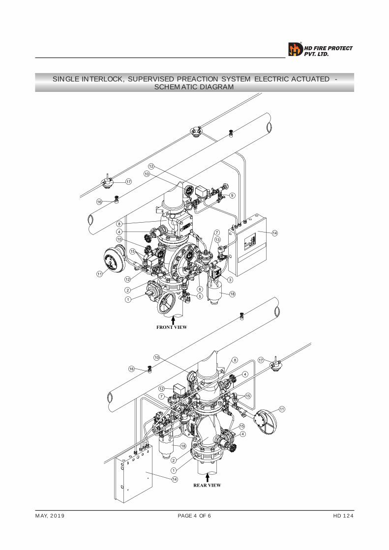
SINGLE INTERLOCK, SUPERVISED PREACTION SYSTEM ELECTRIC ACTUATED - SCHEMATIC DIAGRAM
17
10
12
16
2
1
4
1211
8
10
15
3
7 14
9
6
5
13
18
16
10
12
7
17
14
2
1
4
15
11
15
8
4
18
FRONT VIEW
REAR VIEW
MAY, 2019 HD 124PAGE 5 OF 6
HD FIRE PROTECTPVT. LTD.
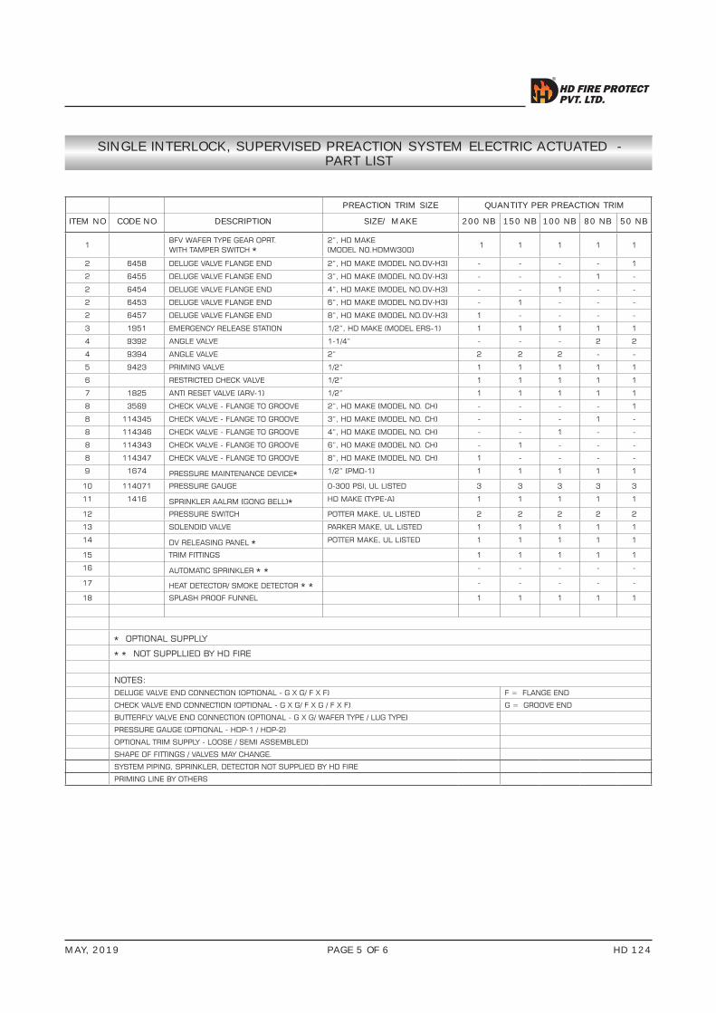
SINGLE INTERLOCK, SUPERVISED PREACTION SYSTEM ELECTRIC ACTUATED - PART LIST
PREACTION TRIM SIZE QUANTITY PER PREACTION TRIM
ITEM NO CODE NO DESCRIPTION SIZE/ MAKE 200 NB 150 NB 100 NB 80 NB 50 NB
1BFV WAFER TYPE GEAR OPRT. WITH TAMPER SWITCH *
2”, HD MAKE (MODEL NO.HDMW300)
1 1 1 1 1
2 6458 DELUGE VALVE FLANGE END 2”, HD MAKE (MODEL NO.DV-H3) - - - - 1
2 6455 DELUGE VALVE FLANGE END 3”, HD MAKE (MODEL NO.DV-H3) - - - 1 -
2 6454 DELUGE VALVE FLANGE END 4”, HD MAKE (MODEL NO.DV-H3) - - 1 - -
2 6453 DELUGE VALVE FLANGE END 6”, HD MAKE (MODEL NO.DV-H3) - 1 - - -
2 6457 DELUGE VALVE FLANGE END 8”, HD MAKE (MODEL NO.DV-H3) 1 - - - -
3 1951 EMERGENCY RELEASE STATION 1/2”, HD MAKE (MODEL ERS-1) 1 1 1 1 1
4 9392 ANGLE VALVE 1-1/4” - - - 2 2
4 9394 ANGLE VALVE 2” 2 2 2 - -
5 9423 PRIMING VALVE 1/2” 1 1 1 1 1
6 RESTRICTED CHECK VALVE 1/2” 1 1 1 1 1
7 1825 ANTI RESET VALVE (ARV-1) 1/2” 1 1 1 1 1
8 3569 CHECK VALVE - FLANGE TO GROOVE 2”, HD MAKE (MODEL NO. CH) - - - - 1
8 114345 CHECK VALVE - FLANGE TO GROOVE 3”, HD MAKE (MODEL NO. CH) - - - 1 -
8 114346 CHECK VALVE - FLANGE TO GROOVE 4”, HD MAKE (MODEL NO. CH) - - 1 - -
8 114343 CHECK VALVE - FLANGE TO GROOVE 6”, HD MAKE (MODEL NO. CH) - 1 - - -
8 114347 CHECK VALVE - FLANGE TO GROOVE 8”, HD MAKE (MODEL NO. CH) 1 - - - -
9 1674 PRESSURE MAINTENANCE DEVICE* 1/2” (PMD-1) 1 1 1 1 1
10 114071 PRESSURE GAUGE 0-300 PSI, UL LISTED 3 3 3 3 3
11 1416 SPRINKLER AALRM (GONG BELL)* HD MAKE (TYPE-A) 1 1 1 1 1
12 PRESSURE SWITCH POTTER MAKE, UL LISTED 2 2 2 2 2
13 SOLENOID VALVE PARKER MAKE, UL LISTED 1 1 1 1 1
14 DV RELEASING PANEL * POTTER MAKE, UL LISTED 1 1 1 1 1
15 TRIM FITTINGS 1 1 1 1 1
16 AUTOMATIC SPRINKLER ** - - - - -
17 HEAT DETECTOR/ SMOKE DETECTOR ** - - - - -
18 SPLASH PROOF FUNNEL 1 1 1 1 1
* OPTIONAL SUPPLLY
** NOT SUPPLLIED BY HD FIRE
NOTES:DELUGE VALVE END CONNECTION (OPTIONAL - G X G/ F X F) F = FLANGE END
CHECK VALVE END CONNECTION (OPTIONAL - G X G/ F X G / F X F) G = GROOVE END
BUTTERFLY VALVE END CONNECTION (OPTIONAL - G X G/ WAFER TYPE / LUG TYPE)
PRESSURE GAUGE (OPTIONAL - HDP-1 / HDP-2)
OPTIONAL TRIM SUPPLY - LOOSE / SEMI ASSEMBLED)
SHAPE OF FITTINGS / VALVES MAY CHANGE.
SYSTEM PIPING, SPRINKLER, DETECTOR NOT SUPPLIED BY HD FIRE
PRIMING LINE BY OTHERS

MAY, 2019 HD 124PAGE 6 OF 6
LIMITED WARRANTY
HD FIRE PROTECT PVT. LTD. hereby referred to as HD FIRE warrants to the original purchaser of the fire protection products manufactured by HD FIRE and to any other person to whom such equipment is transferred, that such products will be free from defect in material and workmanship under normal use and care, for two (2) years from the date of shipment by HD FIRE. Products or Components supplied or used by HD FIRE, but manufactured by others, are warranted only to the extent of the manufacturer’s warranty. No warranty is given for product or components which have been subject to misuse, improper installation, corrosion, unauthorized repair, alteration or un-maintained. HD FIRE shall not be responsible for system design errors or improper installation or inaccurate or incomplete information supplied by buyer or buyer’s representatives.HD FIRE will repair or replace defective material free of charge, which is returned to our factory, transportation charge prepaid, provided after our inspection the material is found to have been defective at the time of initial shipment from our works. HD FIRE shall not be liable for any incidental or consequential loss, damage or expense arising directly or indirectly from the use of the product including damages for injury to person, damages to property and penalties resulting from any products and components manufactured by HD FIRE. HD FIRE shall not be liable for any damages or labour charges or expense in making repair or adjustment to the product. HD FIRE shall not be liable for any damages or charges sustained in the adaptation or use of its engineering data & services. In no event shall HD Fire’s product liability exceed an amount equal to the sale price.The foregoing warranty is exclusive and in lieu of all other warranties and representation whether expressed, implied, oral or written, including but not limited to, any implied warranties or merchantability or fitness for a particular purpose. All such other warranties and representations are hereby cancelled.
NOTICE :The equipment presented in this bulletin is to be installed in accordance with the latest publication standards of NFPA or other similar organisations and also with the provision of government codes or ordinances wherever applicable.The information provided by us is to the best of our knowledge and belief, and consist of general guidelines only. Site handling and installation control is not in our scope. Hence we give no guarantee for result and take no liability for damages, loss or penalties whatsoever, resulting from our suggestion, information, recommendation or damages due to our product.Product development is a continuous programme of HD FIRE PROTECT PVT. LTD. and hence the right to modify any specification without prior notice is reserved with the company.
D-6/2, ROAD NO. 34, WAGLE INDUSTRIAL ESTATE, THANE 400 604, INDIA.• TEL: + (91) 22 2158 2600 • FAX: +(91) 22 2158 2602• EMAIL: [email protected] • WEB: www.hdfire.com
HD FIRE PROTECT PVT. LTD.Protecting What Matters Most to You
HD FIRE PROTECTPVT. LTD.
ORDERING INFORMATION
XX X X
Size
1 50
2 65
3 80
4 100
5 150
6 200
Actuation Device
SE Single Interlock Pre-action with Electric Actuation
Air Maintenance Device
N None
1 PMD-1
2 Nitrogen Air Maintenance Device
Control Panel
N None
A Included
Compressor*
N None
1 1/6 HP
2 1/3 HP
3 1/2 HP
4 3/4 HP
5 1 HP
6 1-1/2 HP
X X X
Compressor Pressure
L 18 PSI
*Compressor standard supply is 50 Hz., 60 Hz is optional supply.