Embed Size (px)
Citation preview
Available online at www.sciencedirect.com
journal homepage: www.elsevier.com/locate/nanoenergy
Nano Energy (2015) 15, 227–234
http://dx.doi.org/12211-2855/& 2015 E
nCorresponding auE-mail address: x
RAPID COMMUNICATION
Single-electrode triboelectric nanogeneratorfor scavenging friction energyfrom rolling tires
Yanchao Maoa,b, Dalong Genga, Erjun Liangb, Xudong Wanga,n
aDepartment of Materials Science and Engineering, University of Wisconsin-Madison, Madison,WI 53706, USAbKey Laboratory of Materials Physics of Ministry of Education of China, School of Physical Science andEngineering, Zhengzhou University, Zhengzhou 450052, China
Received 14 March 2015; received in revised form 14 April 2015; accepted 16 April 2015Available online 6 May 2015
KEYWORDSTriboelectric nano-generator;Mechanical energyharvesting;PDMS;Rolling tires;Wasted frictionenergy
0.1016/j.nanoen.2lsevier Ltd. All rig
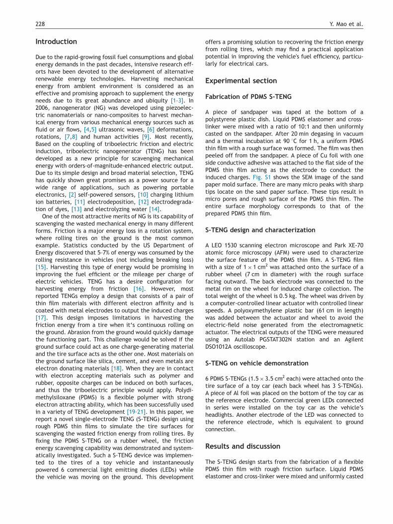
AbstractTriboelectric nanogenerator (TENG) is a novel energy harvesting device to convert mechanicalenergy into electricity based on the universally known triboelectric principle. In this work, wedemonstrated an innovative design of single-electrode TENG (S-TENG) using PDMS to simulatethe tire surfaces for scavenging the wasted friction energy from rolling tires. By fixing the PDMSS-TENG on a rubber wheel, the performance of scavenging friction energy was systematicallyinvestigated. The electric output of the S-TENG-on-wheel monotonically increased with theincrease of the moving speed and weight load of the wheel. The maximum instantaneous powerwas obtained to be 1.79 mW at a load resistance of 10 MΩ, corresponding to the highest energyconversion efficiency of 10.4%. Multiple S-TENGs were implemented to the tires of a toy vehicleand instantaneously powered 6 commercial green light emitting diodes (LEDs) while the vehiclewas moving on the ground. This successful demonstration provides a promising solution toscavenge the wasted friction energy from rolling tires, which may improve the fuel efficiency orthe cruising ability of electric vehicles.& 2015 Elsevier Ltd. All rights reserved.
015.04.026hts reserved.
edu (X. Wang).
Y. Mao et al.228
Introduction
Due to the rapid-growing fossil fuel consumptions and globalenergy demands in the past decades, intensive research eff-orts have been devoted to the development of alternativerenewable energy technologies. Harvesting mechanicalenergy from ambient environment is considered as aneffective and promising approach to supplement the energyneeds due to its great abundance and ubiquity [1–3]. In2006, nanogenerator (NG) was developed using piezoelec-tric nanomaterials or nano-composites to harvest mechan-ical energy from various mechanical energy sources such asfluid or air flows, [4,5] ultrasonic waves, [6] deformations,rotations, [7,8] and human activities [9]. Most recently,Based on the coupling of triboelectric friction and electricinduction, triboelectric nanogenerator (TENG) has beendeveloped as a new principle for scavenging mechanicalenergy with orders-of-magnitude-enhanced electric output.Due to its simple design and broad material selection, TENGhas quickly shown great promises as a power source for awide range of applications, such as powering portableelectronics, [2] self-powered sensors, [10] charging lithiumion batteries, [11] electrodeposition, [12] electrodegrada-tion of dyes, [13] and electrolyzing water [14].
One of the most attractive merits of NG is its capability ofscavenging the wasted mechanical energy in many differentforms. Friction is a major energy loss in a rotation system,where rolling tires on the ground is the most commonexample. Statistics conducted by the US Department ofEnergy discovered that 5–7% of energy was consumed by therolling resistance in vehicles (not including breaking loss)[15]. Harvesting this type of energy would be promising inimproving the fuel efficient or the mileage per charge ofelectric vehicles. TENG has a desire configuration forharvesting energy from friction [16]. However, mostreported TENGs employ a design that consists of a pair ofthin film materials with different electron affinity and iscoated with metal electrodes to output the induced charges[17]. This design imposes limitations in harvesting thefriction energy from a tire when it‘s continuous rolling onthe ground. Abrasion from the ground would quickly damagethe functioning part. This challenge would be solved if theground surface could act as one charge-generating materialand the tire surface acts as the other one. Most materials onthe ground surface like silica, cement, and even metals areelectron donating materials [18]. When they are in contactwith electron accepting materials such as polymer andrubber, opposite charges can be induced on both surfaces,and thus the triboelectric principle would apply. Polydi-methylsiloxane (PDMS) is a flexible polymer with strongelectron attracting ability, which has been successfully usedin a variety of TENG development [19–21]. In this paper, wereport a novel single-electrode TENG (S-TENG) design usingrough PDMS thin films to simulate the tire surfaces forscavenging the wasted friction energy from rolling tires. Byfixing the PDMS S-TENG on a rubber wheel, the frictionenergy scavenging capability was demonstrated and system-atically investigated. Such a S-TENG device was implemen-ted to the tires of a toy vehicle and instantaneouslypowered 6 commercial light emitting diodes (LEDs) whilethe vehicle was moving on the ground. This development
offers a promising solution to recovering the friction energyfrom rolling tires, which may find a practical applicationpotential in improving the vehicle's fuel efficiency, particu-larly for electrical cars.
Experimental section
Fabrication of PDMS S-TENG
A piece of sandpaper was taped at the bottom of apolystyrene plastic dish. Liquid PDMS elastomer and cross-linker were mixed with a ratio of 10:1 and then uniformlycasted on the sandpaper. After 20 min degasing in vacuumand a thermal incubation at 90 1C for 1 h, a uniform PDMSthin film with a rough surface was formed. The film was thenpeeled off from the sandpaper. A piece of Cu foil with oneside conductive adhesive was attached to the flat side of thePDMS thin film acting as the electrode to conduct theinduced charges. Fig. S1 shows the SEM image of the sandpaper mold surface. There are many micro peaks with sharptips locate on the sand paper surface. These tips result inmicro pores and rough surface of the PDMS thin film. Theentire surface morphology corresponds to that of theprepared PDMS thin film.
S-TENG design and characterization
A LEO 1530 scanning electron microscope and Park XE-70atomic force microscopy (AFM) were used to characterizethe surface feature of the PDMS thin film. A S-TENG filmwith a size of 1� 1 cm2 was attached onto the surface of arubber wheel (7 cm in diameter) with the rough surfacefacing outward. The back electrode was connected to themetal rim on the wheel for induced charge collection. Thetotal weight of the wheel is 0.5 kg. The wheel was driven bya computer-controlled linear actuator with controlled linearspeeds. A polyoxymethylene plastic bar (61 cm in length)was added between the actuator and wheel to avoid theelectric-field noise generated from the electromagneticactuator. The electrical outputs of the TENG were measuredusing an Autolab PGSTAT302N station and an AgilentDSO1012A oscilloscope.
S-TENG on vehicle demonstration
6 PDMS S-TENGs (1.5� 3.5 cm2 each) were attached onto thetire surface of a toy car (each back wheel has 3 S-TENGs).A piece of Al foil was placed on the bottom of the toy car asthe reference electrode. Commercial green LEDs connectedin series were installed on the toy car as the vehicle’sheadlights. Another electrode of the LED was connected tothe reference electrode, which is equivalent to groundconnection.
Results and discussion
The S-TENG design starts from the fabrication of a flexiblePDMS thin film with rough friction surface. Liquid PDMSelastomer and cross-linker were mixed and uniformly casted
0 5 10 15 20
-2
-1
0
1
2
2.75 2.80-2
0
2
0 5 10 15 20
-2
-1
0
1
2
Testing Wheel
Metal rim
TENG
ActuatorOscilloscope
Motion
Time (s)
I(μ
A)
Time (s)
V OC(
V)
Time (s)
I SC(
μA)
0µm
10 20 30 40
µm2
1
0
-1
-2
-350 μm
2.65 2.70-2
0
2
Time (s)
V(V
)
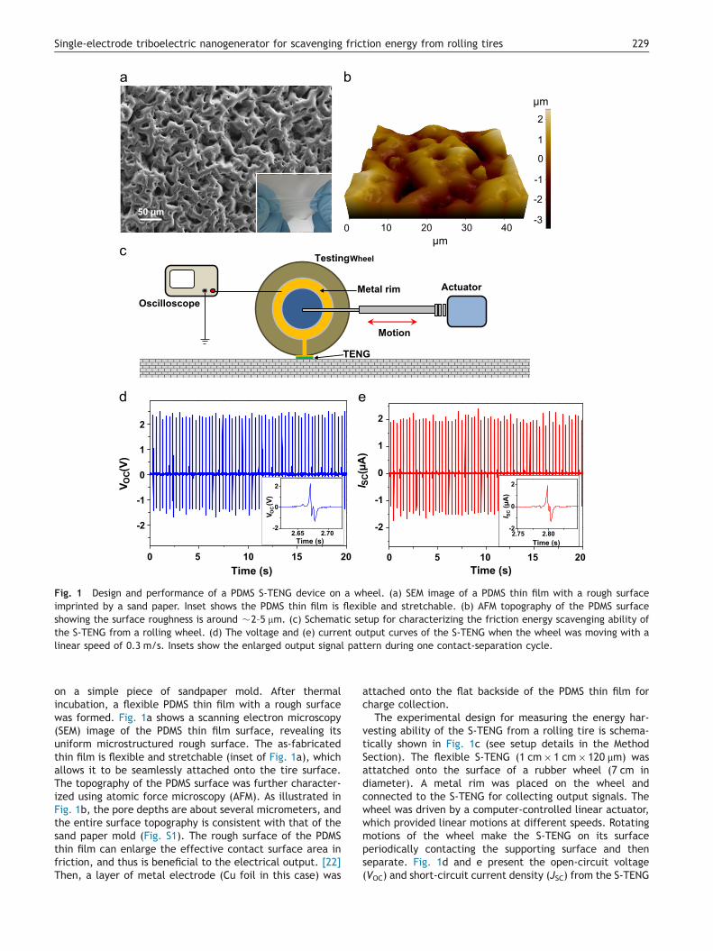
Fig. 1 Design and performance of a PDMS S-TENG device on a wheel. (a) SEM image of a PDMS thin film with a rough surfaceimprinted by a sand paper. Inset shows the PDMS thin film is flexible and stretchable. (b) AFM topography of the PDMS surfaceshowing the surface roughness is around �2–5 mm. (c) Schematic setup for characterizing the friction energy scavenging ability ofthe S-TENG from a rolling wheel. (d) The voltage and (e) current output curves of the S-TENG when the wheel was moving with alinear speed of 0.3 m/s. Insets show the enlarged output signal pattern during one contact-separation cycle.
229Single-electrode triboelectric nanogenerator for scavenging friction energy from rolling tires
on a simple piece of sandpaper mold. After thermalincubation, a flexible PDMS thin film with a rough surfacewas formed. Fig. 1a shows a scanning electron microscopy(SEM) image of the PDMS thin film surface, revealing itsuniform microstructured rough surface. The as-fabricatedthin film is flexible and stretchable (inset of Fig. 1a), whichallows it to be seamlessly attached onto the tire surface.The topography of the PDMS surface was further character-ized using atomic force microscopy (AFM). As illustrated inFig. 1b, the pore depths are about several micrometers, andthe entire surface topography is consistent with that of thesand paper mold (Fig. S1). The rough surface of the PDMSthin film can enlarge the effective contact surface area infriction, and thus is beneficial to the electrical output. [22]Then, a layer of metal electrode (Cu foil in this case) was
attached onto the flat backside of the PDMS thin film forcharge collection.
The experimental design for measuring the energy har-vesting ability of the S-TENG from a rolling tire is schema-tically shown in Fig. 1c (see setup details in the MethodSection). The flexible S-TENG (1 cm� 1 cm� 120 μm) wasattatched onto the surface of a rubber wheel (7 cm indiameter). A metal rim was placed on the wheel andconnected to the S-TENG for collecting output signals. Thewheel was driven by a computer-controlled linear actuator,which provided linear motions at different speeds. Rotatingmotions of the wheel make the S-TENG on its surfaceperiodically contacting the supporting surface and thenseparate. Fig. 1d and e present the open-circuit voltage(VOC) and short-circuit current density (JSC) from the S-TENG
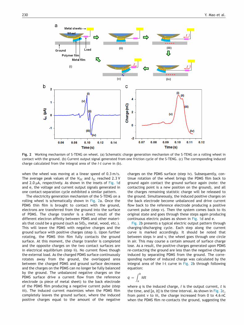
Fig. 2 Working mechanism of S-TENG on wheel. (a) Schematic charge generation mechanism of the S-TENG on a rolling wheel incontact with the ground. (b) Current output signal generated from one friction cycle of the S-TENG. (c) The corresponding inducedcharge calculated from the integral area of the I–t curve in (b).
Y. Mao et al.230
when the wheel was moving at a linear speed of 0.3 m/s.The average peak values of the VOC and ISC reached 2.3 Vand 2.0 μA, respectively. As shown in the insets of Fig. 1dand e, the voltage and current output signals generated inone contact-separation cycle exhibited a similar pattern.
The electricity generation mechanism of the S-TENG on arolling wheel is schematically shown in Fig. 2a. Once thePDMS thin film is brought to contact with the ground,electrons are transferred from the ground into the surfaceof PDMS. The charge transfer is a direct result of thedifferent electron affinity between PDMS and other materi-als that could be a ground (such as SiO2, metal, wood, etc.).This will leave the PDMS with negative charges and theground surface with positive charges (step i). Upon furtherrotating, the PDMS thin film fully contacts the groundsurface. At this moment, the charge transfer is completedand the opposite charges on the two contact surfaces arein electrical equilibrium (step ii). No current flows thoughthe external load. As the charged PDMS surface continuouslyrotates away from the ground, the overlapped areabetween the charged PDMS and ground surface decreasesand the charges on the PDMS can no longer be fully balancedby the ground. The unbalanced negative charges on thePDMS surface drive a current flow from the referenceelectrode (a piece of metal sheet) to the back electrodeof the PDMS film producing a negative current pulse (stepiii). The induced current maximizes when the PDMS filmcompletely leaves the ground surface, where the inducedpositive charges equal to the amount of the negative
charges on the PDMS surface (step iv). Subsequently, con-tinue rotation of the wheel brings the PDMS film back toground again contact the ground surface again (note: thecontacting point is a new position on the ground), and allthe charges remaining statistic charge will be released tothe ground. Simultaneously, the induced positive charges onthe back electrode become unbalanced and drive currentflow back to the reference electrode producing a positivecurrent pulse (step v). Then the system comes back to itsoriginal state and goes through these steps again producingcontinuous electric pulses as shown in Fig. 1d and e.
Fig. 2b presents a typical electric output pattern throughcharging/discharging cycle. Each step along the currentcurve is marked accordingly. It should be noted thatbetween steps iv and v, the wheel goes through one circlein air. This may course a certain amount of surface chargelose. As a result, the positive charges generated upon PDMSre-contacting the ground are less than the negative chargesinduced by separating PDMS from the ground. The corre-sponding number of induced charge was calculated by theintegral area of the I-t curve in Fig. 2b through followingequation:
q ¼Z b
aIdt
where q is the induced charge, I is the output current, t isthe time, and [a, b] is the time interval. As shown in Fig. 2c,from point v to iii, the charge increased from 0 to 4.6 nCwhen the PDMS film re-contacts the ground, suggesting the
105 106 107 108
0.0
0.5
1.0
1.5
2.0
Power
105 106 107 108
2
4
6
8
Current
0
200
400
600
800
Voltage
0.0 0.5 1.0 1.5 2.0 2.50
1
2
3
4Experimental dataFitting curve
0.2 0.3 0.4 0.5
0
1
2
3
4 Experimental dataFitting curve
Speed (m/s)
V OC
(V)
V OC
(V)
Volta
ge (V
)
Resistance (Ω)
Cur
rent
(μA
)
Pow
er (m
W)
Resistance (Ω)
a b
c d
105 106 107 108
0.0
0.5
1.0
Power
105 106 107 108
2
4
6
8
Current
0
200
400
600
800
Voltage
0
1
2
3
4Experimental dataFitting curve
0.2 0.3 0.4 0.5
0
1
2
3
4 Experimental dataFitting curve
V OC
(V)
V OC
(V)
Volta
ge (V
)
(Ω)
Cur
rent
(μA
)
Pow
er (m
W)
( )
Load (kg)
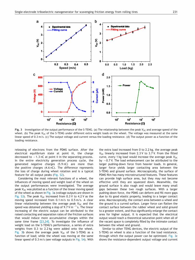
Fig. 3 Investigation of the output performance of the S-TENG. (a) The relationship between the peak VOC and average speed of thewheel. (b) The peak VOC of the S-TENG under different extra weight loads on the wheel. The voltage was measured at the samelinear speed of 0.3 m/s. (c) The output voltage and current versus the loading resistance. (d) The output power as a function of theloading resistance.
231Single-electrode triboelectric nanogenerator for scavenging friction energy from rolling tires
releasing of electrons from the PDMS surface. After theelectrical equilibrium state at point iii, the chargedecreased to �1.3 nC at point ii in the separating process.In the entire electricity generation process cycle, thegenerated negative charges (5.9 nC) are more thanthe positive charges (4.6 nC). The difference representsthe loss of charge during wheel rotation and is a typicalfeature for all output peaks (Fig. S2).
Considering the most relevant functions of a wheel, theinfluences of moving speed and weight load of the wheel onthe output performances were investigated. The averagepeak VOC was plotted as a function of the linear moving speedof the wheel as shown in Fig. 3a (voltage outputs are shown inFig. S3). The peak VOC increased from 0.3 V to 4.2 V as themoving speed increased from 0.1 m/s to 0.5 m/s. A clearlinear relationship between the average peak VOC and thespeed was obtained yielding a slop of 9.7 V m�1 s. The linearincreasing of the electric output can be attributed to theraised contacting and separation rates of the friction surfacesthat would induce more accumulative charges within thesame time frame [23,24]. To investigate the influence ofweight load on the S-TENG’s performance, a series of extraweights from 0.3 to 2.2 kg were added onto the wheel.Fig. 3b shows the average peak VOC of the S-TENG as afunction of load; while the wheel was moving at the samelinear speed of 0.3 m/s (see voltage outputs in Fig. S4). With
the extra load increased from 0 to 2.2 kg, the average peakVOC linearly increased from 2.3 V to 3.7 V. From the fittedcurve, every 1 kg load would increase the average peak VOCby �0.7 V. The load enhancement can be attributed to thelarger pushing-down force from heavier loads. In general,larger force yields larger contacting area between theS-TENG and ground surface. Microscopically, the surface ofPDMS film has many microstructured features. These featurescan provide high surface area, but they may not becomeeffective until they are squeezed down. Meanwhile, theground surface is also rough and would leave many smallgaps between these two rough surfaces. With a largerpushing-down force, the PDMS can deform and fill more gapsdue to its good elastic property, leading to a larger contactarea. Macroscopically, the contact area between a wheel andthe ground is a curved surface. Larger force can flatten thecontact surface between the rubber wheel and solid groundto a greater extent, and thus significantly enlarge the contactarea for higher output. It is expected that the electricaloutput would reach a theoretical saturation point when all ofthe vacant space is completely filled by the intimate contactbetween the wheel and ground.
Similar to other TENG devices, the electric output of theS-TENG on wheel is also a function of the load resistance,through which the output power can be optimized. Fig. 3cshows the resistance-dependent output voltage and current
1 2 3 40
20
40
60
0.0 0.2 0.4 0.6 0.8 1.0 1.2
-2
0
2
4
0.0 0.2 0.4 0.6 0.8 1.0 1.2
-2
0
2
4
0.0 0.2 0.4 0.6 0.8 1.0 1.2
-2
0
2
4
Cha
rge
(nC
)
ISC
(μA
)
I SC
(μA
)
I SC
(μA
)
Time (s) Time (s)
Time (s) NG quantity
0.0 0.2 0.4 0.6 0.8 1.0 1.2
-2
0
2
4
I SC
(μA
)
Time (s)
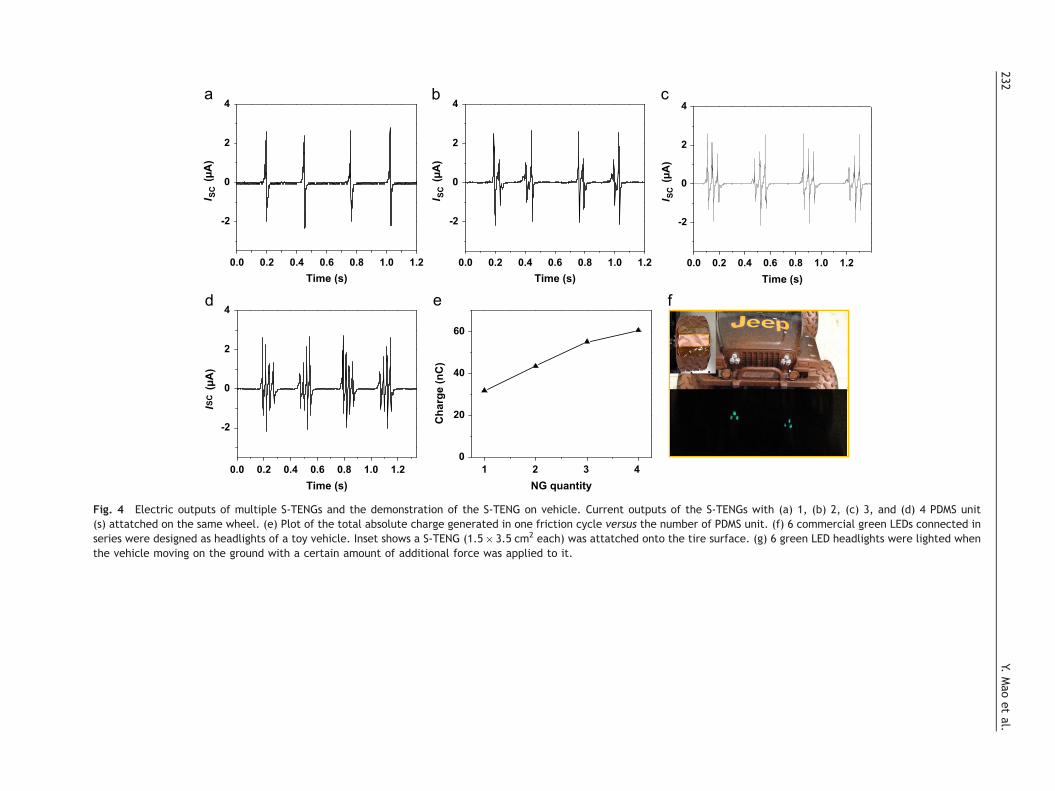
Fig. 4 Electric outputs of multiple S-TENGs and the demonstration of the S-TENG on vehicle. Current outputs of the S-TENGs with (a) 1, (b) 2, (c) 3, and (d) 4 PDMS unit(s) attatched on the same wheel. (e) Plot of the total absolute charge generated in one friction cycle versus the number of PDMS unit. (f) 6 commercial green LEDs connected inseries were designed as headlights of a toy vehicle. Inset shows a S-TENG (1.5� 3.5 cm2 each) was attatched onto the tire surface. (g) 6 green LED headlights were lighted whenthe vehicle moving on the ground with a certain amount of additional force was applied to it.
Y.Mao
etal.
232
233Single-electrode triboelectric nanogenerator for scavenging friction energy from rolling tires
when the load resistor was swept from 0.1 MΩ to 100 MΩ(the wheel was moving at the same speed of 0.3 m/s withnone extra weight loading). The peak VOC increased from afew volts to nearly 700 V as the resistant increased to100 MΩ. Meanwhile, the peak ISC followed an opposite trendand decreased from �8 mA to �2 mA. The instantaneousoutput power was calculated from the products of the peakvoltage and current, and plotted as a function of theresistance (Fig. 3d). The maximum output power was foundto be 1.79 mW at a load resistance of 10 MΩ, correspondingto a power density of 14.92 mW/cm3 for PDMS films. Theenergy conversion efficiency (η) can be calculated from thefollowing equation:
η %ð Þ ¼ UICRRCWv
where CRRC is rolling resistance coefficient (RRC, 0.007 for atypical tire [25]), W is the weight (W=4.9 N at zero extraload), and v is the speed. The highest efficiency reaches10.4% at the load resistance of 10 MΩ.
The output from the wheel rolling can be enhanced byadding multiple S-TENGs on the wheel surface. Fig. 4a–dshows the current outputs when 1, 2, 3, and 4 PDMS S-TENGunits were attached on the same wheel, respectively. Theback electrodes of all the S-TENG were electrically sepa-rated. The total counts of current output peaks in asingle rotation cycle are consistent with the unit quantity.The number of PDMS units has negligible influence on themaximum ISC peak value, which stayed at �2.7 μA. Thetotal number of charge generated in a rotation cycle iscalculated based on the current curve and plotted inFig. 4e. The total induced charge increased monotonicallyfrom 31.8 nC to 60.6 nC as the number of PDMS unitsincreased from 1 to 4. This charge enhancement is expectedto saturate as the entire wheel surface is covered by S-TENG unit.
The successful development of PDMS S-TENG on wheelsfor friction energy harvesting suggests it can be an inherentpart of a tire owing to the single electrode design. As ademonstration, 6 PDMS S-TENGs (1.5� 3.5 cm2 each) wereattached onto the tire surface of a toy car (each back wheelhas 3S-TENGs). The flexible feature of the S-TENG allows itto be well fitted with the tire profile (inset of Fig. 4f).6 commercial green LEDs connected in series were used asthe vehicle’s headlights (Fig. 4f). A piece of Al foil wasplaced on the bottom of the vehicle as the referenceelectrode. When the vehicle was moving on the ground,the generated electricity through triboelectric frictioncould instantaneously light up 2 LED lights (see Video S1 inthe Supporting Information). The equivalent circuit forpowering LEDs is shown in Fig. S5. If a certain amount ofadditional force was applied to the vehicle by hand pushingwhen it was moving, the 6 LED headlights could be poweredsimultaneously, as shown in Fig. 4g and Video S2 (see theSupporting information). It should also be noted that in apractical tire system, the tire surface itself can serve as thePDMS surface. Implanting back electrodes inside the tirebody can realize the same device configuration and functionas a PDMS S-TENG.Supplementary material related to this article can be foundonline at http://dx.doi.org/10.1016/j.nanoen.2015.04.026.
Conclusion
In summary, we demonstrated an innovative design ofS-TENG based on the triboelectric principle using PDMS thinfilms with a rough surface. The PDMS only has one backelectrode for induced charge collection and its front surfaceis in direct contact with the supporting ground. This singleelectrode design offers a unique capability for scavengingthe otherwise-wasted friction energy between a rollingwheel and the ground. The electric output from theS-TENG-on-wheel increased monotonically following theincrease of the moving speed and weight load. By optimizingthe load resistance on the external electric circuit, themaximum instantaneous power was found to be 1.79 mW ata load resistance of 10 MΩ, corresponding to the highestenergy conversion efficiency of 10.4%. Multiple S-TENGs onthe wheel surface can effectively enlarge the number ofinduced charges, and thus improve the electric outputpower. Operation of S-TENGs on the wheels of a toy carwas also demonstrated. When the vehicle was moving onthe ground, the S-TENG generated electricity could instan-taneously power 6 commercial green LEDs without anyenergy storage component. The successful development ofPDMS S-TENG demonstrated a promising application capa-bitliy for scavenging the wasted friction energy between thetires and ground from a running vehicle, and thus improvesthe fuel efficiency or the total mileage per charge ofelectric vehicles.
Acknowledgments
The authors thank financial support from National ScienceFoundation under Award CMMI-1148919 and Air Force underAward FA9550-13-1-0168.
Appendix A. Supplementary information
Supplementary data associated with this article can befound in the online version at http://dx.doi.org/10.1016/j.nanoen.2015.04.026.
References
[1] W. Wu, L. Wang, Y. Li, F. Zhang, L. Lin, S. Niu, D. Chenet,X. Zhang, Y. Hao, T.F. Heinz, J. Hone, Z.L. Wang, Nature 514(2014) 470.
[2] G. Zhu, J. Chen, T. Zhang, Q. Jing, Z.L. Wang, Nat. Commun. 5(2014) 3426.
[3] G. Zhu, Y.S. Zhou, P. Bai, X.S. Meng, Q. Jing, J. Chen, Z.L. Wang, Adv. Mater. 26 (2014) 3788.
[4] B.J. Hansen, Y. Liu, R. Yang, Z.L. Wang, ACS Nano 4 (2010)3647.
[5] C. Sun, J. Shi, D.J. Bayerl, X. Wang, Energy Environ. Sci 4(2011) 4508.
[6] X. Wang, J. Song, J. Liu, Z.L. Wang, Science 316 (2007) 102.[7] T.C. Hou, Y. Yang, Z.H. Lin, Y. Ding, C. Park, K.C. Pradel,
L.J. Chen, Z. Lin Wang, Nano Energy 2 (2013) 387.[8] Q. Jing, G. Zhu, W. Wu, P. Bai, Y. Xie, R.P.S. Han, Z.L. Wang,
Nano Energy 10 (2014) 305.[9] Y. Xie, S. Wang, S. Niu, L. Lin, Q. Jing, J. Yang, Z. Wu,
Z.L. Wang, Adv. Mater. 26 (2014) 6599.
Y. Mao et al.234
[10] S. Wang, L. Lin, Z.L. Wang, Nano Energy 11 (2015) 436.[11] S. Bai, L. Zhang, Q. Xu, Y. Zheng, Y. Qin, Z.L. Wang, Nano
Energy 2 (2013) 749.[12] G. Zhu, C. Pan, W. Guo, C.Y. Chen, Y. Zhou, R. Yu, Z.L. Wang,
Nano Lett. 12 (2012) 4960.[13] Y. Yang, H. Zhang, Y. Liu, Z.H. Lin, S. Lee, Z. Lin, C.P. Wong,
Z.L. Wang, ACS Nano 7 (2013) 2808.[14] W. Tang, Y. Han, C.B. Han, C.Z. Gao, X. Cao, Z.L. Wang, Adv.
Mater. 27 (2015) 272.[15] U.S. Department of Energy, ⟨http://www.fueleconomy.gov/
feg/atv.shtml⟩, 2015.[16] F.R. Fan, Z.Q. Tian, Z. Lin Wang, Nano Energy 1 (2012) 328.[17] Z.H. Lin, G. Cheng, Y. Yang, Y.S. Zhou, S. Lee, Z.L. Wang, Adv.
Funct. Mater. 24 (2014) 2810.[18] M.B. Starr, J. Shi, X. Wang, Angew. Chem. Int. Ed. 51 (2012)
5962.[19] G. Cheng, Z.H. Lin, L. Lin, Z.L. Du, Z.L. Wang, ACS Nano 7
(2013) 7383.[20] Z.H. Lin, G. Zhu, Y.S. Zhou, Y. Yang, P. Bai, J. Chen, Z.L. Wang,
Angew. Chem. Int. Ed. 52 (2013) 5065.[21] G. Cheng, Z.H. Lin, Z. Du, Z.L. Wang, Adv. Funct. Mater. 24
(2014) 2892.[22] Z.H. Lin, G. Cheng, L. Lin, S. Lee, Z.L. Wang, Angew. Chem.
Int. Ed. 52 (2013) 12545.[23] G. Zhu, J. Chen, Y. Liu, P. Bai, Y.S. Zhou, Q. Jing, C. Pan,
Z.L. Wang, Nano Lett. 13 (2013) 2282.[24] H. Zhang, Y. Yang, X. Zhong, Y. Su, Y. Zhou, C. Hu, Z.L. Wang,
ACS Nano 8 (2014) 680.[25] Tires and Passenger Vehicle Fuel Economy, Transportation
Research Board, Special Report 286, National Academy ofSciences, Washington, D.C., 2006.
Dr. Yanchao Mao received his PhD in Physi-cal Chemistry from Sun Yat-Sen University in2014. He was a visiting PhD student in theDepartment of Materials Science and Engi-neering at University of Wisconsin–Madison.He is now a lecturer in the School ofPhysical Science and Engineering at Zhengz-hou University. His research focuses onfabrication of nanomaterials for nanogen-erators and photoelectrochemical water
splitting.Dalong Geng is a graduate student in thedepartment of Materials Science and Engi-neering at University of Wisconsin-Madison.He joined Professor Xudong Wang’s group in2011. His research interests include atomicforce microscopy characterization andnanoscale piezoelectric property study. Hecurrently has been focusing on quantifica-tion of strain gradient-piezoelectric poten-tial relationship on strained piezoelectric
and ferroelectric nanowires.Dr. Erjun Liang is a full Professor in theSchool of Physical Science and Engineering,Zhengzhou University. He received his BS inPhysics from Henan University in 1982, MS inCondensed Matter Physics from HuazhongUniversity of Science and Technology in1988, PhD in Physical Chemistry from theUniversity of Wuerzburg, Germany in 1996.His research interests include MaterialsPhysics and Chemistry, particularly multi-
functional negative thermal expansionmaterials, Plasmonics and Photonics, and Optical Imaging andSpectroscopy. He has published more than 100 papers in peerreviewed scientific journals, contributed 2 book chapters, and holds10 patents.
Dr. Xudong Wang is an associate professorin the department of Materials Science andEngineering at University of Wisconsin–Madi-son. His research interests include studyingthe growth and assembly of oxide nanowirearrays, understanding the coupling effect ofsemiconductor properties and piezoelectriccharge displacement, and developing nano-generator that uses piezoelectric nanoma-terials to convert low level mechanical
energy into electricity. He has published80 papers in peer reviewed scientific journals, contributed 7 bookchapters in his research field, and holds 5 patents/provisionalpatents on oxide nanostructures and nanomaterial-enhanced energyharvesting. His publications have been cited over 6,000 times bypeers and his current h-index is 36.