Embed Size (px)
Citation preview

SET
1
2
3
4
10
9
8
5
IN
VCC
OUT
VSS
STAT1
STAT2 7
6
BAT
PG
ISET
bq24012DRC
+
BATTERY
PACKPACK+
PACK
SYSTEM
SYSTEMINTERFACE
CE
AC ADAPTER
bq24010, bq24012bq24013, bq24014, bq24018
www.ti.com SLUS530K –SEPTEMBER 2002–REVISED JANUARY 2014
Single-Chip, Li-Ion Charge Management IC forHandheld Applications ( bqTINY™)
Check for Samples: bq24010, bq24012, bq24013, bq24014, bq24018
1FEATURESDESCRIPTION
2• Small 3-mm × 3-mm MLP (QFN) PackageThe bqTINY™ series are highly integrated Li-Ion and• Ideal for Low-Dropout Designs for Single-Cell Li-Pol linear charge management devices targeted atLi-Ion or Li-Pol Packs in Space Limited space limited portable applications. The bqTINY™
Applications series offer integrated powerFET and current sensor,• Integrated Power FET and Current Sensor for reverse blocking protection, high accuracy current
and voltage regulation, charge status, and chargeUp to 1-A Charge Applicationstermination, in a small package.• Reverse Leakage Protection Prevents Battery
Drainage The bqTINY™ charges the battery in three phases:conditioning, constant current, and constant voltage.• Integrated Current and Voltage RegulationCharge is terminated based on minimum current. An• ±0.5% Voltage Regulation Accuracy internal charge timer provides a backup safety feature
• Charge Termination by Minimum Current and for charge termination. The bqTINY™ automaticallyTime restarts the charge if the battery voltage falls below
an internal threshold. The bqTINY™ automatically• Pre-Charge Conditioning With Safety Timerenters sleep mode when VCC supply is removed.• Status Outputs for LED or System InterfaceIn addition to the standard features, different versionsIndicates Charge and Fault Conditionsof the bqTINY™ offer a multitude of additional• Battery Insertion and Removal Detection features. These include temperature sensing input for
• Works With Regulated and Unregulated detecting hot or cold battery packs; power good (PG)Supplies output indicating the presence of valid input power; a
TTL-level charge-enable input (CE) used to disable or• Short-Circuit Protectionenable the charge process; and a TTL-level timer and• Charge Voltage Options: 4.2 V and 4.36 V termination enable (TTE) input used to disable orenable the fast-charge timer and charge termination.APPLICATIONS
• Cellular Phones• PDAs• MP3 Players• Digital Cameras• Internet Appliances
1
Please be aware that an important notice concerning availability, standard warranty, and use in critical applications ofTexas Instruments semiconductor products and disclaimers thereto appears at the end of this data sheet.
2bqTINY is a trademark of Texas Instruments.PRODUCTION DATA information is current as of publication date. Copyright © 2002–2014, Texas Instruments IncorporatedProducts conform to specifications per the terms of the TexasInstruments standard warranty. Production processing does notnecessarily include testing of all parameters.

bq24010, bq24012bq24013, bq24014, bq24018SLUS530K –SEPTEMBER 2002–REVISED JANUARY 2014 www.ti.com
This integrated circuit can be damaged by ESD. Texas Instruments recommends that all integrated circuits be handled withappropriate precautions. Failure to observe proper handling and installation procedures can cause damage.
ESD damage can range from subtle performance degradation to complete device failure. Precision integrated circuits may be moresusceptible to damage because very small parametric changes could cause the device not to meet its published specifications.
ABSOLUTE MAXIMUM RATINGS (1)
VALUE UNITSupply voltage range, (VCC all with respect to VSS) –0.3 to 18 V
IN, STAT1, STAT2, TS, PG, CE, TTE –0.3 to VCC VInput voltage range (2)
BAT, OUT, ISET –0.3 to 7 VDCVoltage difference between VCC and IN inputs VCC – VIN ±0.5 VOutput sink/source current STAT1, STAT2, PG 15Output current IN, OUT 1.5
TA Operating free-air temperature range–40 to 125 °C
TJ Junction temperature rangeTstg Storage temperature –65 to 150 °C
(1) Stresses beyond those listed under absolute maximum ratings may cause permanent damage to the device. These are stress ratingsonly, and functional operation of the device at these or any other conditions beyond those indicated under recommended operatingconditions is not implied. Exposure to absolute-maximum-rated conditions for extended periods may affect device reliability.
(2) All voltages are DC and with respect to VSS.
DISSIPATION RATINGSTA < 40°C DERATING FACTORPACKAGE θJA POWER RATING ABOVE TA = 40°C
DRC (1) 47°C/W 1.5 W 0.021 W/°C1
(1) This data is based on using the JEDEC High-K board and the exposed die pad is connected to a copper pad on the board. This isconnected to the ground plane by a 2x3 via matrix.
RECOMMENDED OPERATING CONDITIONSover operating free-air temperature range (unless otherwise noted)
MIN NOM MAX UNITVCC Supply voltage (1) (2) 3 16.5 VVIN Input voltage (1) (2) 3 16.5 VTJ Operating junction temperature range –40 125 °C
(1) Pins VCC and IN must be tied together.(2) If Vin is between UVLO and 4.35V, and above the battery voltage, then the IC is active (can deliver some charge to the battery), but the
IC will have limited or degraded performance (some functions may not meet data sheet specifications). The battery may beundercharged (VO(reg) less than in the specification), but will not be overcharged (VO(reg) will not exceed specification).
ELECTRICAL CHARACTERISTICSover 0°C ≤ TJ ≤ 125°C and recommended supply voltage, (unless otherwise noted)
PARAMETER TEST CONDITIONS MIN TYP MAX UNIT
INPUT CURRENT
ICC(VCC) VCC current VCC > VCC(min), STATx pins in OFF state 0 3.5 5 mA
ICC(SLP) Sleep current Sum of currents into OUT and BAT pins, VCC < V(SLP) 5 μA
IIB(BAT) Input bias current on BAT pin 500 nA
IIB(TS) Input current on TS pin VI(TS) ≤ 10 V 1
IIB(CE) Input current on CE pin 1 μA
IIB(TTE) Input bias current on TTE pin 1
VOLTAGE REGULATION VO(REG) + V(DO–MAX) ≤ VCC, I(TERM) < IO(OUT) ≤ 1 A
bq24010, bq24012, bq24013, bq24014 4.2 VOutput voltage, VO(REG)
bq24018 4.36
2 Submit Documentation Feedback Copyright © 2002–2014, Texas Instruments Incorporated
Product Folder Links: bq24010, bq24012 bq24013, bq24014, bq24018

( )SET PRECHG
SETO(PRECHG)
K x V( ) ( )I =
R( )
æ öç ÷mç ÷è ø
ISETISET
ISETO(OUT)
V( )I = K + 10 A( ) x
R( )
( )SET SET
SETO(OUT)
K x V( ) ( )I =
R( )(1)
(4)
bq24010, bq24012bq24013, bq24014, bq24018
www.ti.com SLUS530K –SEPTEMBER 2002–REVISED JANUARY 2014
ELECTRICAL CHARACTERISTICS (continued)over 0°C ≤ TJ ≤ 125°C and recommended supply voltage, (unless otherwise noted)
PARAMETER TEST CONDITIONS MIN TYP MAX UNIT
TA = 25°C –0.5% 0.5%Voltage regulation accuracy
–1% 1%
V(DO) Dropout voltage (V(IN) – V(OUT)) VO(REG) + V(DO–MAX)) ≤ VCC, IO(OUT) = 1A 650 790 mV
CURRENT REGULATION
VCC ≥ 4.5 V, VIN ≥ 4.5 V, VI(BAT) > V(LOWV), 100 1000VIN – VI(BAT) > V(DO–MAX)IO(OUT)(1) Output current range mA
See note (2) 25 100
bq24010,bq24012,Voltage on ISET pin, VCC ≥ 4.5 V, 2.45 2.50 2.55 Vbq24013,V(SET) Output current set voltage VIN ≥ 4.5 V, VI(BAT) > V(LOWV), bq24014VIN – VI(BAT) > V(DO–MAX), VO(REG) = 4.2 Vbq24018 2.548 2.6 2.652 V
50 mA ≤ IO(OUT) ≤ 1000 mA, V(LOWV) < V(OUT) < V(RCH) 315 335 355
25 mA ≤ IO(OUT) < 50 mA, V(LOWV) < V(OUT) < V(RCH) 315 372 430
K(SET) Output current ISET factor 10 mA ≤ IO(OUT) < 100 mA, V(OUT) < V(LOWV) 350 1000
2.5 mA ≤ IO(OUT) < 10 mA, V(OUT) < V(LOWV) 450
2.5 mA ≤ IO(OUT) < I(PGM), V(OUT) < V(RCH) 355 (3)
PRE-CHARGE AND SHORT-CIRCUIT CURRENT REGULATION
Pre-charge to fast-charge transitionV(LOWV) Voltage on BAT pin 2.80 2.95 3.10 Vthreshold
Pre-charge to short-charge transitionV(SC) Voltage on BAT pin 1 1.4 1.8 Vthreshold
IO(PRECHG)(4) Pre-charge range V(SC) < VI(BAT) < V(LOWV), t < t(PRECHG) 10 100 mV
V(PRECHG) Pre-charge set voltage Voltage on ISET pin, V(SC) < VI(BAT) < V(LOWV) 225 250 280 mV
ISC Short circuit current V(SC) > VI(BAT) 660 900 1200 μA
(2) Specified by design. Not production tested.(3) The ISET pin may be used as a current monitor during voltage regulation by applying the following equation:
This equation is also used for calculating the termination point.
Copyright © 2002–2014, Texas Instruments Incorporated Submit Documentation Feedback 3
Product Folder Links: bq24010, bq24012 bq24013, bq24014, bq24018

( )SET TAPER
SETO(TAPER)
K x V( ) ( )I =
R( )(1)
bq24010, bq24012bq24013, bq24014, bq24018SLUS530K –SEPTEMBER 2002–REVISED JANUARY 2014 www.ti.com
ELECTRICAL CHARACTERISTICS (Continued)over 0°C ≤ TJ ≤ 125°C and recommended supply voltage, (unless otherwise noted)
PARAMETER TEST CONDITIONS MIN TYP MAX UNIT
CHARGE TAPER AND TERMINATION DETECTION
I(TAPER)(1) Charge taper detection range VI(BAT) > V(RCH), t < t(TAPER) 10 100 mA
Voltage on ISET pin, VI(BAT) > V(RCH), t < t(TAPER),V(TAPER) Charge taper detection set voltage 225 250 275 mVVI(BAT) = VO(REG)
Charge termination detection set Voltage on ISET pin, VI(BAT) = VO(REG),V(TERM) 5 17.5 50 mVvoltage VI(BAT) >V(RCH),I(TERM) = K(SET) × V(TERM) /R(SET)
TEMPERATURE COMPARATOR
V(TS1) Lower threshold Voltage on TS pin 29 30 31
V(TS2) Upper threshold Voltage on TS pin 60 61 62 %VCC
Hysteresis 1
BATTERY RECHARGE THRESHOLD
VO(REG) VO(REG) VO(REG)V(RCH) Recharge threshold V–0.135 –0.1 –0.075
STAT1, STAT2, AND PG OUTPUTS
VOL Output (low) saturation voltage IO = 10 mA 0.5 V
CHARGE ENABLE (CE) AND TIMER AND TERMINATION ENABLE (TTE) INPUTS
VIL Low-level input voltage IIL = 1 μA 0 0.8V
VIH High-level input voltage IIL = 1 μA 2.0
TIMERS
t{PRECHG) Pre-charge time 1 548 2,065 2,581
t(TAPER) Taper time 1 548 2,065 2,581 s
t(CHG) Charge time 15 480 20,650 25,810
SLEEP COMPARATOR
VCC ≤VSLP Sleep mode entry threshold voltage VPOR ≤ V(IBAT) ≤ VO(REG) VI(BAT)
+30 mVV
VCC ≥Sleep mode exit threshold voltage VPOR ≤ V(IBAT) ≤ VO(REG) VI(BAT)
+22 mV
VCC decreasing below threshold, 100-ns fall time, 10-mVSleep mode deglitch time 250 650 msoverdrive
BATTERY DETECTION THRESHOLDS
I(DETECT) Battery detection current 2 V ≤ V(IBAT) ≤ V(RCH) –3.1 –4.6 –6.1 mA
I(DETECT) battery detection time 2 V ≤ V(IBAT) ≤ V(RCH) 100 125 150 ms
I(FAULT) Fault current V(IBAT) < V(RCH) and/or t > t(PRECHG) 660 900 1200 μA
POWER-ON RESET AND INPUT VOLTAGE RAMP RATE
VPOR(2) Power-on reset threshold voltage 225 2.5 2.75 V
(2) Specified by design. Not production tested.
4 Submit Documentation Feedback Copyright © 2002–2014, Texas Instruments Incorporated
Product Folder Links: bq24010, bq24012 bq24013, bq24014, bq24018

DRC PACKAGE
(TOP VIEW)
VSS
5
STAT2
4
STAT1
3
VCC
2
IN
1
6 7 8 9 10
ISET PG TS BAT OUT
bq24010DRC
DRC PACKAGE
(TOP VIEW)
VSS
5
STAT2
4
STAT1
3
VCC
2
IN
1
6 7 8 9 10
ISET PG CE BAT OUT
bq24012DRC
DRC PACKAGE
(TOP VIEW)
VSS
5
STAT2
4
STAT1
3
VCC
2
IN
1
6 7 8 9 10
ISET CE TTE BAT OUT
DRC PACKAGE
(TOP VIEW)
VSS
5
STAT2
4
STAT1
3
VCC
2
IN
1
6 7 8 9 10
ISET CE TS BAT OUT
bq24014DRC
bq24013DRCand
bq24018DRC
bq24010, bq24012bq24013, bq24014, bq24018
www.ti.com SLUS530K –SEPTEMBER 2002–REVISED JANUARY 2014
DEVICE INFORMATION
Copyright © 2002–2014, Texas Instruments Incorporated Submit Documentation Feedback 5
Product Folder Links: bq24010, bq24012 bq24013, bq24014, bq24018

bq24010, bq24012bq24013, bq24014, bq24018SLUS530K –SEPTEMBER 2002–REVISED JANUARY 2014 www.ti.com
Table 1. TERMINAL FUNCTIONSTERMINAL
bq24013 I/O DESCRIPTIONNAME bq24010 bq24012 and bq24014
bq24018BAT 9 9 9 9 I Battery voltage sense inputCE – 8 7 7 I Charge enable input (active low)IN 1 1 1 1 I Charge input voltage. This input must be tied to the VCC pin.ISET 6 6 6 6 O Charge current set pointOUT 10 10 10 10 O Charge current outputPG 7 7 – – O Power good status output (open collector)STAT1 3 3 3 3 O Charge status output 1 (open collector)STAT2 4 4 4 4 O Charge status output 2 (open collector)TTE – – 8 – I Timer and termination enable input (active low)TS 8 – – 8 I Temperature sense inputVCC 2 2 2 2 I VCC supply inputVSS 5 5 5 5 – Ground input
There is an internal electrical connection between the exposedthermal pad and VSS pin of the device. The exposed thermal padExposed must be connected to the same potential as the Vss pin on theThermal Pad Pad Pad Pad – printed circuit board. Do not use the thermal pad as the primaryPAD ground input for the device. VSS pin must be connected to groundat all times.
6 Submit Documentation Feedback Copyright © 2002–2014, Texas Instruments Incorporated
Product Folder Links: bq24010, bq24012 bq24013, bq24014, bq24018

VI(BAT)VO(REG)
I(DETECT) I(FAULT)ENABLE ENABLE
VI(BAT)
V(SLP)
I(DETECT) ENABLE
I(FAULT) ENABLE
VI(BAT)
VI(BAT)
VI(BAT)
VI(SET)
VI(SET)
VO(REG)
VO(REG)
V(ISET)
VSET
CE
Dotted lines represent optional features
IN
VCC
+
+
DEGLITCH
OUT
ISET
REFERENCEAND BIAS
VCC
BAT
VCC
TS
CHARGECONTROL,
TIMER,AND
DISPLAYLOGIC
THERMALSHUTDOWN
PRECHARGE
DEGLITCH
DEGLITCH
DEGLITCH
RECHARGE
TAPER
CHG ENABLE
STAT1
STAT2TERM
VSS
VCC
CHG ENABLE
CHG ENABLE
TTEPG
V(RCH)
VSET
V(TAPER)
V(TERM)
V(PRECHG)
PG
bq24010, bq24012bq24013, bq24014, bq24018
www.ti.com SLUS530K –SEPTEMBER 2002–REVISED JANUARY 2014
FUNCTIONAL BLOCK DIAGRAM
TYPICAL CHARACTERISTICS
Copyright © 2002–2014, Texas Instruments Incorporated Submit Documentation Feedback 7
Product Folder Links: bq24010, bq24012 bq24013, bq24014, bq24018

USB PORT
D+
D-
VBUS
GND
0.47 Fm
1
2
3
4
5
10
9
8
7
6
IN
VCC
STAT1
STAT2
VSS
OUT
BAT
TTE
CE
ISET
0.1 Fm
2.26 kW
9.09 kW
PACK-
PACK+
BATTERYPACK
+
SYSTEMandUSB
CONTROLLER
100 mA / 500 mA
SI1032x
bq24013DRCbq24018DRC
DC +
1
2
3
4
10
9
8
5
IN
VCC
OUT
VSS
STAT1
STAT2 7
6
BAT
TS
PG
ISET
bq24010DRC
+
BATTERYPACK
PACK+
PACK
RT1
RT2
VCC
CHARGE
DONE
POWERGOOD
0.1 Fm
RSET
DC-
0.47 Fm
bq24010, bq24012bq24013, bq24014, bq24018SLUS530K –SEPTEMBER 2002–REVISED JANUARY 2014 www.ti.com
FUNCTIONAL DESCRIPTION
The bqTINY™ supports a precision Li-Ion, Li-Pol charging system suitable for single-cells. Figure 2 shows atypical charge profile, application circuit, and Figure 5 shows an operational flow chart.
Figure 3. Typical Application Circuit
Figure 4. USB Charger Circuit
8 Submit Documentation Feedback Copyright © 2002–2014, Texas Instruments Incorporated
Product Folder Links: bq24010, bq24012 bq24013, bq24014, bq24018

Yes
No
No
Yes
Indicate Fault
Yes
No
Yes
No
Regulate Current
or Voltage
No
POR
Yes
No
Yes
No
No
Fault Condition
Yes
Yes
Indicate DONE
Turn off charge
Indicate SLEEP
MODE
SLEEP MODE
Suspend charge
No
No
Yes
No
No
Yes
YesNo
Yes
Enter Battery
Absent
Detection
No
Yes
Yes
VCC > VI(BAT)checked at
all times
VI(BAT) < V(LOWV)Reset and Startt(PRECHG) timer
RegulateIO(PRECHG)
Reset all timersstart t(CHG)
timers
VI(BAT) < V(LOWV)
TJ < t(SHTDWN)
TJ < t(SHTDWN)
t(PRECHG)expired?
t(CHG)expired?
VI(BAT) < V(LOWV)
EnableI(FAULT)
current?
VI(BAT) > V(RCH)?
VI(BAT) > V(RCH)?
I(TERM)detection
?
t(TAPER)expired?
DisableI(FAULT)
current?
VI(BAT) < V(RCH)?
I(TAPER)detection
?
IndicateCharge-in-Progress
IndicateCharge Suspend
IndicateCharge-in-Progress
bq24010, bq24012bq24013, bq24014, bq24018
www.ti.com SLUS530K –SEPTEMBER 2002–REVISED JANUARY 2014
Figure 5. Operational Flow Chart
Copyright © 2002–2014, Texas Instruments Incorporated Submit Documentation Feedback 9
Product Folder Links: bq24010, bq24012 bq24013, bq24014, bq24018

( )( ) ( )
TH TC
TC TH
T2
5 x R x RR =
2 x R - 7 x R
( )
( )( )TH TC
TC TH
T1
5 x R x RR =
3 x R - R
Charge Suspend
Normal Temperature Range
Charge Suspend
V(TS2)
V(TS1)
VSS
VCC
bq24010, bq24012bq24013, bq24014, bq24018SLUS530K –SEPTEMBER 2002–REVISED JANUARY 2014 www.ti.com
TEMPERATURE QUALIFICATION
NOTEThe temperature qualifications apply only to versions with temperature sense input (TS)pin option (bq24020 and bq24014).
Versions of the bqTINY with the TS pin option, continuously monitor battery temperature by measuring thevoltage between the TS and VSS pins. A negative temperature coefficient thermistor (NTC) and an externalvoltage divider typically develops this voltage (see Figure 3). The bqTINY compare this voltage against theinternal V(TS1) and V(TS2) thresholds to determine if charging is allowed (see Figure 6). The temperature sensingcircuit is immune to any fluctuation in VCC since both the external voltage divider and the internal thresholds areratiometric to VCC.
Once a temperature outside the V(TS1) and V(TS2) thresholds is detected the bqTINY immediately suspend thecharge. The bqTINY suspends charge by turning off the power FET and holding the timer value (i.e. timers areNOT reset). Charge resumes when the temperature returns to the typical range.
Figure 6. TS Pin Thresholds
The resistor values of RT1 and RT2 are calculated by Equation 1 and Equation 2 (for NTC Thermistors).
(1)
(2)
Where RTC is the cold temperature resistance and RTH is the hot temperature resistance of thermistor, asspecified by the thermistor manufacturer.
RT1 or RT2 can be omitted If only one temperature (hot or cold) setting is required. Applying a constant voltagebetween the VTS1 and VTS2 thresholds to pin TS disables the temperature-sensing feature.
10 Submit Documentation Feedback Copyright © 2002–2014, Texas Instruments Incorporated
Product Folder Links: bq24010, bq24012 bq24013, bq24014, bq24018

( )TERM SET
SET(TERM)
V x K( ) ( )I =
R( )
( )TAPER SET
SET(TAPER)
V x K( ) ( )I =
R( )
( )SET SET
SETO(OUT)
K x V( ) ( )I =
R( )
( )PRECHG SET
SETO(PRECHG)
V x K( ) ( )I =
R( )
bq24010, bq24012bq24013, bq24014, bq24018
www.ti.com SLUS530K –SEPTEMBER 2002–REVISED JANUARY 2014
BATTERY PRE-CONDITIONINGDuring a charge cycle, if the battery voltage is below the V(LOWV) threshold, the bqTINY applies a pre-chargecurrent, IO(PRECHG), to the battery. This feature revives deeply discharged cells. The resistor connected betweenthe ISET and VSS, RSET, determines the pre-charge rate. The V(PRECHG) and K(SET) parameters are specified inthe specifications table.
(3)
The bqTINY activates a safety timer, t(PRECHG), during the conditioning phase. If V(LOWV) threshold is not reachedwithin the timer period, the bqTINY turns off the charger and enunciates FAULT on the STAT1 and STAT2 pins.Refer to Timer Fault Recovery section for additional details.
BATTERY CHARGE CURRENTThe bqTINY offers on-chip current regulation with programmable set point. The resistor connected between theISET and VSS, RSET, determines the charge rate. The V(SET) and K(SET) parameters are specified in thespecifications table.
(4)
BATTERY VOLTAGE REGULATIONVoltage regulation feedback is accomplished through the BAT pin. This input is tied directly and close to thepositive side of the battery pack. The bqTINY monitors the battery-pack voltage between the BAT and VSS pins.When the battery voltage rises to VO(REG) threshold, the voltage regulation phase begins and the charging currentbegins to taper down.
As a safety backup, the bqTINY also monitors the charge time in the charge mode. If termination does not occurwithin this time period, t(CHG), the bqTINY turns off the charger and enunciates FAULT on the STAT1 and STAT1pins. Refer to the Timer Fault Recovery section for additional details.
CHARGE TAPER DETECTION, TERMINATION AND RECHARGEThe bqTINY monitors the charging current during the voltage regulation phase. Once the taper threshold, I(TAPER),is detected the bqTINY initiates the taper timer, t(TAPER). Charge terminates after the timer expires. The resistorconnected between the ISET and VSS, RSET, determines the taper detection level. The V(TAPER) and K(SET)parameters are specified in the specifications table.
(5)
The bqTINY resets the taper timer in the event that the charge current returns above the taper threshold, I(TAPER).
In addition to the taper current detection, the bqTINY terminates charge in the event that the charge current fallsbelow the I(TERM) threshold. This feature allows for quick recognition of a battery removal condition or insertion ofa fully charged battery. Note that taper timer is not used for I(TERM) detection. The resistor connected between theISET and VSS, RSET, determines the taper detection level. The V(TERM) and K(SET) parameters are specified in thespecifications table.
(6)
Copyright © 2002–2014, Texas Instruments Incorporated Submit Documentation Feedback 11
Product Folder Links: bq24010, bq24012 bq24013, bq24014, bq24018

bq24010, bq24012bq24013, bq24014, bq24018SLUS530K –SEPTEMBER 2002–REVISED JANUARY 2014 www.ti.com
After charge termination, the bqTINY restarts the charge once the voltage on the BAT pin falls below the V(RCH)threshold. This feature keeps the battery at full capacity at all times. See the Battery Absent Detection section foradditional details.
SLEEP MODEThe bqTINY enters the low-power sleep mode if the VCC is removed from the circuit (PG pin is high impedance).This feature prevents draining the battery during the absence of VCC. The status pins do not function when insleep mode or when VCC < VPOR and default to the OFF state.
CHARGE STATUS OUTPUTSThe open-collector STAT1 and STAT2 outputs indicate various charger operations as shown in the followingtable. These status pins can be used to drive LEDs or communicate to the host processor. Note that OFFindicates the open-collector transistor is turned off. When VCC < VPOR or VCC < VBAT (Sleep Mode – PG OFF) theSTAT pins default to their OFF state. Note that this STAT1 or STAT2 OFF/OFF state is shared by severaloperating conditions. Decode the actual fault condition by monitoring IN, BAT, PG, and TS.
Table 2. Status Pins SummaryCHARGE STATE STAT1 STAT2
Charge-in-progress ON OFFCharge done OFF (1) ONBattery absentCharge suspend (temperature) OFF OFFTimer faultSleep mode
(1) OFF means the open-collector output transistor on the STAT1 orSTAT2 pins is in an off state.
PG OUTPUTThe open-collector PG (power good) indicates when the AC adapter (i.e., VCC) is present. The PG bipolartransistor turns ON when a valid VCC is detected. This output is turned off in the sleep mode. The PG pin can beused to drive an LED or communicate to the host processor.
CE INPUT (CHARGE ENABLE)The CE digital input is used to disable or enable the charge process. A low-level signal on this pin enables thecharge and a high-level signal disables the charge. A high-to-low transition on this pin also resets all timers andfault conditions and starts a new charge cycle.
TTE INPUT (TIMER AND TERMINATION ENABLE)The TTE digital input is used to disable or enable the fast-charge timer and charge termination. A low-level signalon this pin enables the fast-charge timer and termination and a high-level signal disables this feature. A high-to-low transition on this pin also resets all timers.
THERMAL SHUTDOWN AND PROTECTIONThe bqTINY monitors the junction temperature, TJ, of the die and suspends charging if TJ exceeds 155°C.Charging resumes when TJ falls below approximately 130°C.
12 Submit Documentation Feedback Copyright © 2002–2014, Texas Instruments Incorporated
Product Folder Links: bq24010, bq24012 bq24013, bq24014, bq24018

No
Yes
Yes
No
No
Yes
VI(BAT) <V(RCH)
EnableI(DETECT) for
t(DETECT)
VI(BAT) <V(LOWV)
BATTERYPRESENT
Begin Charge
BATTERYPRESENT
BeginCharge
ApplyIO(PRECHG) for
t(DETECT)
VI(BAT) >V(RCH)
BATTERYABSENT
Charge Doneor
Timer Fault
bq24010, bq24012bq24013, bq24014, bq24018
www.ti.com SLUS530K –SEPTEMBER 2002–REVISED JANUARY 2014
BATTERY ABSENT DETECTIONFor applications with removable battery packs, bqTINY provides a battery absent detection scheme to reliablydetect insertion or removal of battery packs, or both.
The voltage at the BAT pin is held above the battery recharge threshold, V(RCH), by the charged battery followingfast charging. When the voltage at the BAT pin falls to the recharge threshold, either by a load on the battery ordue to battery removal, the bqTINY begins a battery absent detection test. This test involves enabling a detectioncurrent, I(DETECT), for a period of t(DETECT) and checking to see if the battery voltage is below the pre-chargethreshold, V(LOWV). Following this, the pre-charge current, IO(PRECHG) is applied for a period of t(DETECT) and thebattery voltage checked again to be above the recharge threshold. The purpose is to attempt to close a batterypack with an open protector, if one is connected to the bqTINY. Passing both of the discharge and charging testsindicates a battery absent fault at the STAT pins. Failure of either test starts a new charge cycle. For the absentbattery condition the voltage on the BAT pin rises and falls between the V(LOWV) and VO(REG) thresholdsindefinitely. See Figure 7.
Figure 7. Battery Absent Detection
Copyright © 2002–2014, Texas Instruments Incorporated Submit Documentation Feedback 13
Product Folder Links: bq24010, bq24012 bq24013, bq24014, bq24018

bq24010, bq24012bq24013, bq24014, bq24018SLUS530K –SEPTEMBER 2002–REVISED JANUARY 2014 www.ti.com
TIMER FAULT RECOVERYAs shown in Figure 5, bqTINY provides a recovery method to deal with timer fault conditions. The followingconditions summarize this method.
Condition 1: Charge voltage above recharge threshold (V(RCH)) and timeout fault occurs
Recovery method: bqTINY waits for the battery voltage to fall below the recharge threshold. This could happenas a result of a load on the battery, self-discharge, or battery removal. Once the battery falls below the rechargethreshold, the bqTINY clears the fault and enters the battery absent detection routine. A POR or CE toggle alsoclears the fault.
Condition 2: Charge voltage below recharge threshold (V(RCH)) and timeout fault occurs.
Recovery method: Under this scenario, the bqTINY applies the I(FAULT) current. This small current is used todetect a battery removal condition and remains on as long as the battery voltage stays below the rechargethreshold. If the battery voltage goes above the recharge threshold, then the bqTINY disables the I(FAULT) currentand executes the recovery method described for condition #1. Once the battery falls below the rechargethreshold, the bqTINY clears the fault and enters the battery absent detection routine. A POR or CE toggle alsoclears the fault.
14 Submit Documentation Feedback Copyright © 2002–2014, Texas Instruments Incorporated
Product Folder Links: bq24010, bq24012 bq24013, bq24014, bq24018

( )IN I(BAT) O(OUT)P = V - V x I
J AJA
T x T=
Pq
bq24010, bq24012bq24013, bq24014, bq24018
www.ti.com SLUS530K –SEPTEMBER 2002–REVISED JANUARY 2014
APPLICATION INFORMATION
SELECTING INPUT CAPACITORIn most applications, all that is needed is a high-frequency decoupling capacitor. A 0.47-μF ceramic, placed inclose proximity to VCC and VSS pins, works well. The bqTINY is designed to work with both regulated andunregulated external DC supplies. If a non-regulated supply is chosen, the supply unit should have enoughcapacitance to hold up the supply voltage to the minimum required input voltage at maximum load. If not, morecapacitance has to be added to the input of the charger.
SELECTING OUTPUT CAPACITORThe bqTINY requires only a small output capacitor for loop stability. A 0.1-μF ceramic capacitor placed betweenthe BAT and ISET pins is typically sufficient for embedded applications (for example non-removable batterypacks). For application with removable battery packs a 1-μF ceramic capacitor ensure proper operation of thebattery detection circuitry. Note that the output capacitor can also be placed between BAT and VSS pins.
THERMAL CONSIDERATIONSThe bqTINY is packaged in a thermally enhanced MLP (also referred to as QFN) package. The package includesa thermal pad to provide an effective thermal contact between the device and the printed circuit board (PCB).Full PCB design guidelines for this package are provided in the application note entitled, QFN/SON PCBAttachment application note (SLUA271).
The most common measure of package thermal performance is thermal impedance (θJA) measured (or modeled)from the device junction to the air surrounding the package surface (ambient). The mathematical expression forθJA is:
(7)
Where:TJ = device junction temperatureTA = ambient temperatureP = device power dissipation
Factors that can greatly influence the measurement and calculation of θJA include:• Whether or not the device is board mounted• Trace size, composition, thickness, and geometry• Orientation of the device (horizontal or vertical)• Volume of the ambient air surrounding the device under test and airflown• Whether other surfaces are in close proximity to the device being tested
The device power dissipation, P, is a function of the charge rate and the voltage drop across the internalPowerFET. It can be calculated from the following equation:
(8)
Due to the charge profile of Li-xx batteries, the maximum power dissipation is typically seen at the beginning ofthe charge cycle when the battery voltage is at its lowest. See Figure 2.
Copyright © 2002–2014, Texas Instruments Incorporated Submit Documentation Feedback 15
Product Folder Links: bq24010, bq24012 bq24013, bq24014, bq24018

bq24010, bq24012bq24013, bq24014, bq24018SLUS530K –SEPTEMBER 2002–REVISED JANUARY 2014 www.ti.com
PCB LAYOUT CONSIDERATIONSIt is important to pay special attention to the PCB layout. The following list provides some guidelines:• To obtain optimal performance, the decoupling capacitor from VCC to VSS and the output filter capacitors from
BAT to ISET should be placed as close as possible to the bqTINY, with short trace runs to both signal andVSS pins.
• All low-current VSS connections should be kept separate from the high-current charge or discharge paths fromthe battery. Use a single-point ground technique incorporating both the small signal ground path and thepower ground path.
• The BAT pin is the voltage feedback to the device and should be connected with its trace as close to thebattery pack as possible.
• The high current charge paths into IN and from the OUT pins must be sized appropriately for the maximumcharge current in order to avoid voltage drops in these traces.
• The bqTINY is packaged in a thermally enhanced MLP package. The package includes a thermal pad toprovide an effective thermal contact between the device and the printed circuit board (PCB). Full PCB designguidelines for this package are provided in the application note entitled: QFN/SON PCB AttachmentApplication Note (SLUA271).
• There is an internal electrical connection between the exposed thermal pad and VSS pin of the device. Theexposed thermal pad must be connected to the same potential as the VSS pin on the printed circuit board. Donot use the thermal pad as the primary ground input for the device. VSS pin must be connected to ground atall times.
REVISION HISTORY
Changes from Revision J (December 2008) to Revision K Page
• Updated IO(OUT) equation ....................................................................................................................................................... 3
16 Submit Documentation Feedback Copyright © 2002–2014, Texas Instruments Incorporated
Product Folder Links: bq24010, bq24012 bq24013, bq24014, bq24018
PACKAGE OPTION ADDENDUM
www.ti.com 15-Apr-2017
Addendum-Page 1
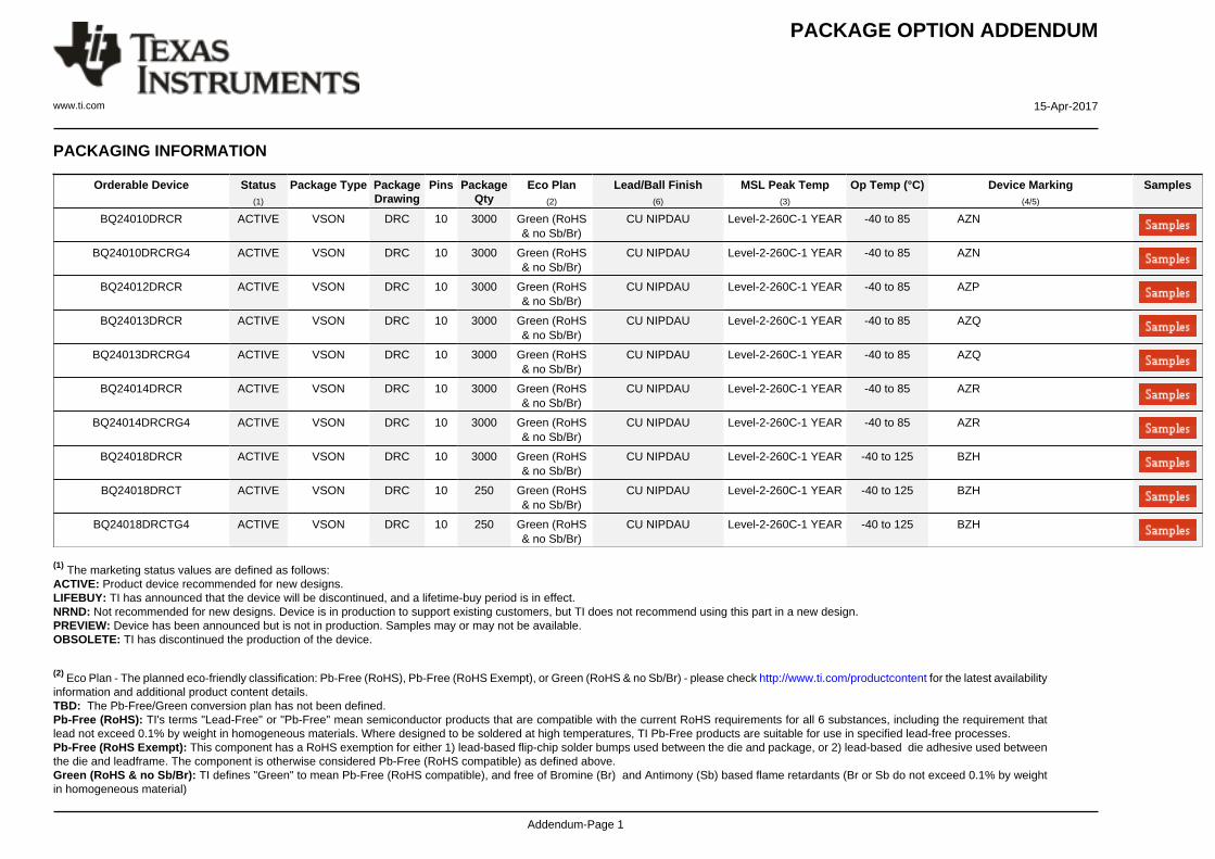
PACKAGING INFORMATION
Orderable Device Status(1)
Package Type PackageDrawing
Pins PackageQty
Eco Plan(2)
Lead/Ball Finish(6)
MSL Peak Temp(3)
Op Temp (°C) Device Marking(4/5)
Samples
BQ24010DRCR ACTIVE VSON DRC 10 3000 Green (RoHS& no Sb/Br)
CU NIPDAU Level-2-260C-1 YEAR -40 to 85 AZN
BQ24010DRCRG4 ACTIVE VSON DRC 10 3000 Green (RoHS& no Sb/Br)
CU NIPDAU Level-2-260C-1 YEAR -40 to 85 AZN
BQ24012DRCR ACTIVE VSON DRC 10 3000 Green (RoHS& no Sb/Br)
CU NIPDAU Level-2-260C-1 YEAR -40 to 85 AZP
BQ24013DRCR ACTIVE VSON DRC 10 3000 Green (RoHS& no Sb/Br)
CU NIPDAU Level-2-260C-1 YEAR -40 to 85 AZQ
BQ24013DRCRG4 ACTIVE VSON DRC 10 3000 Green (RoHS& no Sb/Br)
CU NIPDAU Level-2-260C-1 YEAR -40 to 85 AZQ
BQ24014DRCR ACTIVE VSON DRC 10 3000 Green (RoHS& no Sb/Br)
CU NIPDAU Level-2-260C-1 YEAR -40 to 85 AZR
BQ24014DRCRG4 ACTIVE VSON DRC 10 3000 Green (RoHS& no Sb/Br)
CU NIPDAU Level-2-260C-1 YEAR -40 to 85 AZR
BQ24018DRCR ACTIVE VSON DRC 10 3000 Green (RoHS& no Sb/Br)
CU NIPDAU Level-2-260C-1 YEAR -40 to 125 BZH
BQ24018DRCT ACTIVE VSON DRC 10 250 Green (RoHS& no Sb/Br)
CU NIPDAU Level-2-260C-1 YEAR -40 to 125 BZH
BQ24018DRCTG4 ACTIVE VSON DRC 10 250 Green (RoHS& no Sb/Br)
CU NIPDAU Level-2-260C-1 YEAR -40 to 125 BZH
(1) The marketing status values are defined as follows:ACTIVE: Product device recommended for new designs.LIFEBUY: TI has announced that the device will be discontinued, and a lifetime-buy period is in effect.NRND: Not recommended for new designs. Device is in production to support existing customers, but TI does not recommend using this part in a new design.PREVIEW: Device has been announced but is not in production. Samples may or may not be available.OBSOLETE: TI has discontinued the production of the device.
(2) Eco Plan - The planned eco-friendly classification: Pb-Free (RoHS), Pb-Free (RoHS Exempt), or Green (RoHS & no Sb/Br) - please check http://www.ti.com/productcontent for the latest availabilityinformation and additional product content details.TBD: The Pb-Free/Green conversion plan has not been defined.Pb-Free (RoHS): TI's terms "Lead-Free" or "Pb-Free" mean semiconductor products that are compatible with the current RoHS requirements for all 6 substances, including the requirement thatlead not exceed 0.1% by weight in homogeneous materials. Where designed to be soldered at high temperatures, TI Pb-Free products are suitable for use in specified lead-free processes.Pb-Free (RoHS Exempt): This component has a RoHS exemption for either 1) lead-based flip-chip solder bumps used between the die and package, or 2) lead-based die adhesive used betweenthe die and leadframe. The component is otherwise considered Pb-Free (RoHS compatible) as defined above.Green (RoHS & no Sb/Br): TI defines "Green" to mean Pb-Free (RoHS compatible), and free of Bromine (Br) and Antimony (Sb) based flame retardants (Br or Sb do not exceed 0.1% by weightin homogeneous material)

PACKAGE OPTION ADDENDUM
www.ti.com 15-Apr-2017
Addendum-Page 2
(3) MSL, Peak Temp. - The Moisture Sensitivity Level rating according to the JEDEC industry standard classifications, and peak solder temperature.
(4) There may be additional marking, which relates to the logo, the lot trace code information, or the environmental category on the device.
(5) Multiple Device Markings will be inside parentheses. Only one Device Marking contained in parentheses and separated by a "~" will appear on a device. If a line is indented then it is a continuationof the previous line and the two combined represent the entire Device Marking for that device.
(6) Lead/Ball Finish - Orderable Devices may have multiple material finish options. Finish options are separated by a vertical ruled line. Lead/Ball Finish values may wrap to two lines if the finishvalue exceeds the maximum column width.
Important Information and Disclaimer:The information provided on this page represents TI's knowledge and belief as of the date that it is provided. TI bases its knowledge and belief on informationprovided by third parties, and makes no representation or warranty as to the accuracy of such information. Efforts are underway to better integrate information from third parties. TI has taken andcontinues to take reasonable steps to provide representative and accurate information but may not have conducted destructive testing or chemical analysis on incoming materials and chemicals.TI and TI suppliers consider certain information to be proprietary, and thus CAS numbers and other limited information may not be available for release.
In no event shall TI's liability arising out of such information exceed the total purchase price of the TI part(s) at issue in this document sold by TI to Customer on an annual basis.

TAPE AND REEL INFORMATION
*All dimensions are nominal
Device PackageType
PackageDrawing
Pins SPQ ReelDiameter
(mm)
ReelWidth
W1 (mm)
A0(mm)
B0(mm)
K0(mm)
P1(mm)
W(mm)
Pin1Quadrant
BQ24010DRCR VSON DRC 10 3000 330.0 12.4 3.3 3.3 1.1 8.0 12.0 Q2
BQ24010DRCR VSON DRC 10 3000 330.0 12.4 3.3 3.3 1.1 8.0 12.0 Q2
BQ24012DRCR VSON DRC 10 3000 330.0 12.4 3.3 3.3 1.1 8.0 12.0 Q2
BQ24012DRCR VSON DRC 10 3000 330.0 12.4 3.3 3.3 1.1 8.0 12.0 Q2
BQ24013DRCR VSON DRC 10 3000 330.0 12.4 3.3 3.3 1.1 8.0 12.0 Q2
BQ24013DRCR VSON DRC 10 3000 330.0 12.4 3.3 3.3 1.1 8.0 12.0 Q2
BQ24014DRCR VSON DRC 10 3000 330.0 12.4 3.3 3.3 1.1 8.0 12.0 Q2
BQ24014DRCR VSON DRC 10 3000 330.0 12.4 3.3 3.3 1.1 8.0 12.0 Q2
BQ24018DRCR VSON DRC 10 3000 330.0 12.4 3.3 3.3 1.1 8.0 12.0 Q2
BQ24018DRCT VSON DRC 10 250 180.0 12.4 3.3 3.3 1.1 8.0 12.0 Q2
PACKAGE MATERIALS INFORMATION
www.ti.com 1-Oct-2014
Pack Materials-Page 1

*All dimensions are nominal
Device Package Type Package Drawing Pins SPQ Length (mm) Width (mm) Height (mm)
BQ24010DRCR VSON DRC 10 3000 367.0 367.0 35.0
BQ24010DRCR VSON DRC 10 3000 338.0 355.0 50.0
BQ24012DRCR VSON DRC 10 3000 367.0 367.0 35.0
BQ24012DRCR VSON DRC 10 3000 338.0 355.0 50.0
BQ24013DRCR VSON DRC 10 3000 367.0 367.0 35.0
BQ24013DRCR VSON DRC 10 3000 338.0 355.0 50.0
BQ24014DRCR VSON DRC 10 3000 367.0 367.0 35.0
BQ24014DRCR VSON DRC 10 3000 338.0 355.0 50.0
BQ24018DRCR VSON DRC 10 3000 367.0 367.0 35.0
BQ24018DRCT VSON DRC 10 250 210.0 185.0 35.0
PACKAGE MATERIALS INFORMATION
www.ti.com 1-Oct-2014
Pack Materials-Page 2

GENERIC PACKAGE VIEW
Images above are just a representation of the package family, actual package may vary.Refer to the product data sheet for package details.
DRC 10 VSON - 1 mm max heightPLASTIC SMALL OUTLINE - NO LEAD
4204102-3/M

www.ti.com
PACKAGE OUTLINE
C
10X 0.300.18
2.4 0.1
2X2
1.65 0.1
8X 0.5
1 MAX
10X 0.50.3
0.050.00
A 3.12.9
B
3.12.9
(0.2) TYP4X (0.25)
2X (0.5)
VSON - 1 mm max heightDRC0010JPLASTIC SMALL OUTLINE - NO LEAD
4218878/A 09/2017
PIN 1 INDEX AREA
SEATING PLANE
0.08 C
1
56
10
(OPTIONAL)PIN 1 ID 0.1 C A B
0.05 C
THERMAL PADEXPOSED
SYMM
SYMM11
NOTES: 1. All linear dimensions are in millimeters. Any dimensions in parenthesis are for reference only. Dimensioning and tolerancing per ASME Y14.5M. 2. This drawing is subject to change without notice. 3. The package thermal pad must be soldered to the printed circuit board for optimal thermal and mechanical performance.
SCALE 4.000
www.ti.com
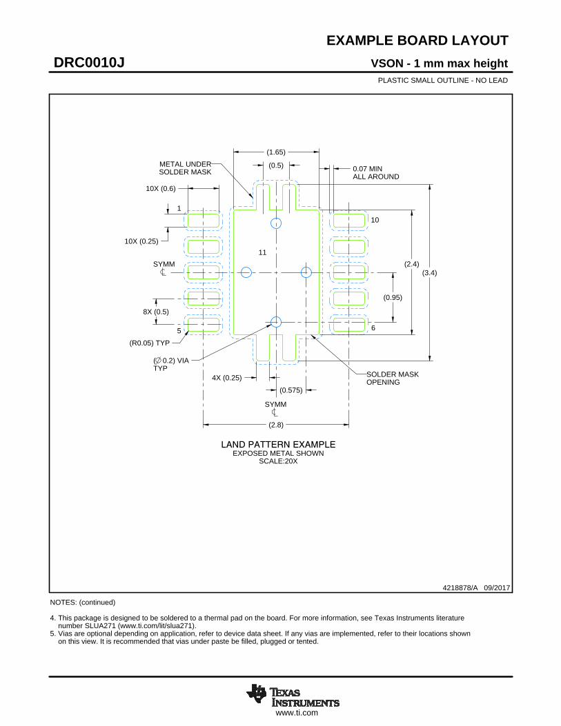
EXAMPLE BOARD LAYOUT
0.07 MINALL AROUND
10X (0.25)
(2.4)
(2.8)
8X (0.5)
(1.65)
( 0.2) VIATYP
(0.575)
(0.95)
10X (0.6)
(R0.05) TYP
(3.4)
4X (0.25)
(0.5)
VSON - 1 mm max heightDRC0010JPLASTIC SMALL OUTLINE - NO LEAD
4218878/A 09/2017
SYMM
1
5 6
10
LAND PATTERN EXAMPLEEXPOSED METAL SHOWN
SCALE:20X
11SYMM
METAL UNDERSOLDER MASK
SOLDER MASKOPENING
NOTES: (continued) 4. This package is designed to be soldered to a thermal pad on the board. For more information, see Texas Instruments literature number SLUA271 (www.ti.com/lit/slua271).5. Vias are optional depending on application, refer to device data sheet. If any vias are implemented, refer to their locations shown on this view. It is recommended that vias under paste be filled, plugged or tented.

www.ti.com
EXAMPLE STENCIL DESIGN
(R0.05) TYP
10X (0.25)
10X (0.6)
2X (1.5)
2X(1.06)
(2.8)
(0.63)
8X (0.5)
(0.5)
4X (0.34)
4X (0.25)
(1.53)
VSON - 1 mm max heightDRC0010JPLASTIC SMALL OUTLINE - NO LEAD
4218878/A 09/2017
NOTES: (continued) 6. Laser cutting apertures with trapezoidal walls and rounded corners may offer better paste release. IPC-7525 may have alternate design recommendations.
SOLDER PASTE EXAMPLEBASED ON 0.125 mm THICK STENCIL
EXPOSED PAD 11:
80% PRINTED SOLDER COVERAGE BY AREASCALE:25X
SYMM
1
56
10
EXPOSED METALTYP
11
SYMM
SOLDER MASK OPENING
METAL UNDERSOLDER MASK

IMPORTANT NOTICE
Texas Instruments Incorporated (TI) reserves the right to make corrections, enhancements, improvements and other changes to itssemiconductor products and services per JESD46, latest issue, and to discontinue any product or service per JESD48, latest issue. Buyersshould obtain the latest relevant information before placing orders and should verify that such information is current and complete.TI’s published terms of sale for semiconductor products (http://www.ti.com/sc/docs/stdterms.htm) apply to the sale of packaged integratedcircuit products that TI has qualified and released to market. Additional terms may apply to the use or sale of other types of TI products andservices.Reproduction of significant portions of TI information in TI data sheets is permissible only if reproduction is without alteration and isaccompanied by all associated warranties, conditions, limitations, and notices. TI is not responsible or liable for such reproduceddocumentation. Information of third parties may be subject to additional restrictions. Resale of TI products or services with statementsdifferent from or beyond the parameters stated by TI for that product or service voids all express and any implied warranties for theassociated TI product or service and is an unfair and deceptive business practice. TI is not responsible or liable for any such statements.Buyers and others who are developing systems that incorporate TI products (collectively, “Designers”) understand and agree that Designersremain responsible for using their independent analysis, evaluation and judgment in designing their applications and that Designers havefull and exclusive responsibility to assure the safety of Designers' applications and compliance of their applications (and of all TI productsused in or for Designers’ applications) with all applicable regulations, laws and other applicable requirements. Designer represents that, withrespect to their applications, Designer has all the necessary expertise to create and implement safeguards that (1) anticipate dangerousconsequences of failures, (2) monitor failures and their consequences, and (3) lessen the likelihood of failures that might cause harm andtake appropriate actions. Designer agrees that prior to using or distributing any applications that include TI products, Designer willthoroughly test such applications and the functionality of such TI products as used in such applications.TI’s provision of technical, application or other design advice, quality characterization, reliability data or other services or information,including, but not limited to, reference designs and materials relating to evaluation modules, (collectively, “TI Resources”) are intended toassist designers who are developing applications that incorporate TI products; by downloading, accessing or using TI Resources in anyway, Designer (individually or, if Designer is acting on behalf of a company, Designer’s company) agrees to use any particular TI Resourcesolely for this purpose and subject to the terms of this Notice.TI’s provision of TI Resources does not expand or otherwise alter TI’s applicable published warranties or warranty disclaimers for TIproducts, and no additional obligations or liabilities arise from TI providing such TI Resources. TI reserves the right to make corrections,enhancements, improvements and other changes to its TI Resources. TI has not conducted any testing other than that specificallydescribed in the published documentation for a particular TI Resource.Designer is authorized to use, copy and modify any individual TI Resource only in connection with the development of applications thatinclude the TI product(s) identified in such TI Resource. NO OTHER LICENSE, EXPRESS OR IMPLIED, BY ESTOPPEL OR OTHERWISETO ANY OTHER TI INTELLECTUAL PROPERTY RIGHT, AND NO LICENSE TO ANY TECHNOLOGY OR INTELLECTUAL PROPERTYRIGHT OF TI OR ANY THIRD PARTY IS GRANTED HEREIN, including but not limited to any patent right, copyright, mask work right, orother intellectual property right relating to any combination, machine, or process in which TI products or services are used. Informationregarding or referencing third-party products or services does not constitute a license to use such products or services, or a warranty orendorsement thereof. Use of TI Resources may require a license from a third party under the patents or other intellectual property of thethird party, or a license from TI under the patents or other intellectual property of TI.TI RESOURCES ARE PROVIDED “AS IS” AND WITH ALL FAULTS. TI DISCLAIMS ALL OTHER WARRANTIES ORREPRESENTATIONS, EXPRESS OR IMPLIED, REGARDING RESOURCES OR USE THEREOF, INCLUDING BUT NOT LIMITED TOACCURACY OR COMPLETENESS, TITLE, ANY EPIDEMIC FAILURE WARRANTY AND ANY IMPLIED WARRANTIES OFMERCHANTABILITY, FITNESS FOR A PARTICULAR PURPOSE, AND NON-INFRINGEMENT OF ANY THIRD PARTY INTELLECTUALPROPERTY RIGHTS. TI SHALL NOT BE LIABLE FOR AND SHALL NOT DEFEND OR INDEMNIFY DESIGNER AGAINST ANY CLAIM,INCLUDING BUT NOT LIMITED TO ANY INFRINGEMENT CLAIM THAT RELATES TO OR IS BASED ON ANY COMBINATION OFPRODUCTS EVEN IF DESCRIBED IN TI RESOURCES OR OTHERWISE. IN NO EVENT SHALL TI BE LIABLE FOR ANY ACTUAL,DIRECT, SPECIAL, COLLATERAL, INDIRECT, PUNITIVE, INCIDENTAL, CONSEQUENTIAL OR EXEMPLARY DAMAGES INCONNECTION WITH OR ARISING OUT OF TI RESOURCES OR USE THEREOF, AND REGARDLESS OF WHETHER TI HAS BEENADVISED OF THE POSSIBILITY OF SUCH DAMAGES.Unless TI has explicitly designated an individual product as meeting the requirements of a particular industry standard (e.g., ISO/TS 16949and ISO 26262), TI is not responsible for any failure to meet such industry standard requirements.Where TI specifically promotes products as facilitating functional safety or as compliant with industry functional safety standards, suchproducts are intended to help enable customers to design and create their own applications that meet applicable functional safety standardsand requirements. Using products in an application does not by itself establish any safety features in the application. Designers mustensure compliance with safety-related requirements and standards applicable to their applications. Designer may not use any TI products inlife-critical medical equipment unless authorized officers of the parties have executed a special contract specifically governing such use.Life-critical medical equipment is medical equipment where failure of such equipment would cause serious bodily injury or death (e.g., lifesupport, pacemakers, defibrillators, heart pumps, neurostimulators, and implantables). Such equipment includes, without limitation, allmedical devices identified by the U.S. Food and Drug Administration as Class III devices and equivalent classifications outside the U.S.TI may expressly designate certain products as completing a particular qualification (e.g., Q100, Military Grade, or Enhanced Product).Designers agree that it has the necessary expertise to select the product with the appropriate qualification designation for their applicationsand that proper product selection is at Designers’ own risk. Designers are solely responsible for compliance with all legal and regulatoryrequirements in connection with such selection.Designer will fully indemnify TI and its representatives against any damages, costs, losses, and/or liabilities arising out of Designer’s non-compliance with the terms and provisions of this Notice.
Mailing Address: Texas Instruments, Post Office Box 655303, Dallas, Texas 75265Copyright © 2018, Texas Instruments Incorporated