Embed Size (px)
Citation preview
ARTICLE IN PRESS
0952-1976/$ - se
doi:10.1016/j.en
�Fax: +90 23
E-mail addr
Engineering Applications of Artificial Intelligence 18 (2005) 881–890
www.elsevier.com/locate/engappai
Single-chip fuzzy logic controller design and an applicationon a permanent magnet dc motor
Sinan Pravadalioglu�
I.M.Y.O., Control Sys. Department, Dokuz Eylul University, Menderes cad, Istasyon sok 5, Buca, 35170 Izmir, Turkey
Received 27 March 2004; accepted 11 March 2005
Available online 23 May 2005
Abstract
This paper describes a low-cost single-chip PI-type fuzzy logic controller design and an application on a permanent magnet dc
motor drive. The presented controller application calculates the duty cycle of the PWM chopper drive and can be used to dc–dc
converters as well. The self-tuning capability makes the controller robust and all the tasks are carried out by a single chip reducing
the cost of the system and so program code optimization is achieved. A simple, but effective algorithm is developed to calculate
numerical values instead of linguistic rules. In this way, external memory usage is eliminated. The contribution of this paper is to
present the feasibility of a high-performance non-linear fuzzy logic controller which can be implemented by using a general purpose
microcontroller without modified fuzzy methods. The developed fuzzy logic controller was simulated in MATLAB/SIMULINK.
The theoretical and experimental results indicate that the implemented fuzzy logic controller has a high performance for real-time
control over a wide range of operating conditions.
r 2005 Elsevier Ltd. All rights reserved.
Keywords: Dc motor drive; Fuzzy logic controller; Microcontroller; Application; Simulation
1. Introduction
In switch-mode power supplies, the transformation ofdc voltage from one level to another level is dc–dcconversion and accomplished by using dc–dc convertercircuits, which offers higher efficiency than linearregulators. They have great importance in manypractical electronic systems, including home appliances,computers and communication equipment. They arealso widely used in industry, especially in switch-modedc power supplies and in dc motor drive applications.The dc–dc converter accepts an unregulated dc inputvoltage and produces a controlled dc output at desiredvoltage level. They can step-up, step-down and invertthe input dc voltage and transfer energy from input tooutput in discrete packets. The one disadvantage ofdc–dc converters is noise. At every period to charge in
e front matter r 2005 Elsevier Ltd. All rights reserved.
gappai.2005.03.004
2 3362171.
ess: [email protected].
discrete packets, it creates noise or ripple. The noise canbe minimized using specific control techniques and withconvenient component selection. There are well-knowncontrol techniques including pulse-width modulation(PWM) where the switch frequency is constant and theduty cycle varies with the load.
PWM technique affords high efficiency over a wideload range. In addition, because the switching frequencyis fixed, the noise spectrum is relatively narrow, allowingsimple low-pass filter techniques to reduce the peak-to-peak voltage ripple. For this same reason, PWM ispopular with telecom power supply applications wherenoise interference is of concern.
The most important requirement of a control systemfor the dc–dc converter is to maintain the output voltageconstant irrespective of variations in the dc inputvoltage and the load current. However, load changesaffect the output transiently and cause significantdeviations from the steady-state level of dc outputvoltage, which must be controlled to equal a desired

ARTICLE IN PRESSS. Pravadalioglu / Engineering Applications of Artificial Intelligence 18 (2005) 881–890882
level by the control systems. The inherent switching of adc–dc converter results in the circuit components beingconnected periodically changing configurations, eachconfiguration being described by a set of separateequations. Transient analysis and control system designfor a converter is therefore difficult since a number ofequations must be solved in sequence. Although thestate-space averaging is the most commonly used modelto obtain linear transfer functions to solve this problem,it neglects significant parts of non-linear behavior ofdc–dc converters. Development of non-linear controllersfor dc–dc converters have gained considerable attentionin recent years.
A fuzzy logic model based controller is chosen as thenon-linear controller for this study. Fuzzy logic control(FLC) has been an important research topic. Despite thelack of concrete theoretical basis many successfulapplications on FLC were reported and variousapplications for dc–dc converters and electrical driveshave been published and can be found in the literature(So et al., 1996, 1995; Mattavelli et al., 1997; Brandsetterand Sedlak, 1996; Hyo et al., 2001; Gupta et al., 1997;Zakharov, 1996; Vas, 1998, 1999). FLC has a wide-spread application on the non-linear and complexsystems as well as linear systems due to its capabilityto control the systems that might not have a transferfunction between input and output variables. Experi-ences show that fuzzy control can yield superior resultsto those obtained by conventional control algorithms.
In the meantime, new fuzzy microcontroller chips areavailable on the market and are able to execute fuzzyrules very fast with their mask programmed algorithmsthat have some drawbacks such as restriction inimplementing any desired algorithm. Digital signalprocessing (DSP) integrated circuits (IC) are capableof computing and processing the system variables veryquickly with high precision. But most of the DSPcircuits are expensive and do not contain peripheralssuch as analog to digital (A/D) and digital to analog (D/A) circuits for conversion and PWM generator on chip,and need to be added externally. A fuzzy controllerapplication among the others on dc–dc converters useda TMS320-DSP and fuzzy controller with an evaluationmodule plus some external chips. They were an A/Dconverter for feedback signal evaluation, a D/Aconverter for converting the calculated quantity into acontrol output and a PWM chip to generate theappropriate duty cycle for the semiconductor switchingelements (So et al., 1995; Brandsetter and Sedlak, 1996).An implementation of an FLC with 8-bit conventionalmicrocontroller is presented in Gupta et al. (1997) fordc–dc converters and a modified centroid method fordefuzzification process is used to reduce the processingtime of 8-bit microcontroller. However, this modifieddefuzzification technique increases the settling time ofthe system. A detailed simulation and experimental
study on the closed-loop control of dc motor drive withFLC is carried out in Zakharov (1996) and a PCcomputer with an evaluation board is employed forFLC. The transient response of proportional integral(PI)-type current and speed controllers are compared tothat of the FLC.
The aim of the study presented in this paper isto design and to implement a high-performancefuzzy tuned PI controller for controlling the rotorspeed of permanent magnet dc motor (PMDCM).We also provide a way of designing such a controllerin a cost effective way by using a general purpose single-chip microcontroller. This design is implemented with-out making the assumptions for the modification ofdefuzzification process which was presented in Guptaet al. (1997). This leads to an improved performanceof the transient and steady state of the closed-loopsystem.
The experimental results are also compared to thesimulation result obtained from MATLAB/SIMU-LINK.
2. Permanent magnet dc motor and class C chopper
A PMDCM fed via class C chopper can be describedby the state-space form in the continuous time asfollows:
d
dt
iaðtÞ
wðtÞ
" #¼
�Ra=La �Kaj=La
Kaj=J �Bv=J
" #iaðtÞ
wðtÞ
" #
þ1=La 0
0 �1=J
" #VaðtÞ
TLðtÞ
" #, ð1Þ
where Ra is armature resistance (Ohm), La is armatureinductance (Henry), Kaj is back electromotive forceand torque constant (V/rad/s or Nm/A), J is totalmoment of inertia (kgm2) and Bv is viscous frictionconstant (Nm/rad/s). V aðtÞ represents the voltageapplied to armature by a class C type of chopper givenin Fig. 1.
The average value of armature voltage is a function ofton, period of chopping and the level of dc input voltageas shown in Fig. 2.
In analog control systems, the repetitive sawtoothwaveform is compared with the control voltage togenerate the PWM gate signals to the MOSFETsemployed in the chopper. The duty cycle is equal tothe ratio between control voltage (Ec) and the peak ofsawtooth. The control voltage signal is generallyobtained amplifying the difference between the actualoutput voltage and its desired value. Simple controls canbe carried out using analog IC, such as operationalamplifier circuits but sophisticated control tasks usuallyinvolves the using of digital ICs, microcontrollers or

ARTICLE IN PRESS
Fig. 2. Voltage waveforms of Class C type of chopper.
Fig. 1. Dc motor and Class C chopper.
S. Pravadalioglu / Engineering Applications of Artificial Intelligence 18 (2005) 881–890 883
DSPs to support high-performance, repetitive, numeri-cally intensive tasks. Building a closed-loop controlsystem, the actual output voltage can be sensed by atacho generator which produces an output voltageproportional to armature rotation. Development andapplication of FLC in electrical drives have drawngreater attention in recent years (Vas, 1998, 1999).
3. Fuzzy controller
Conventional controllers are derived from controltheory techniques based on mathematical models of theprocess. They are characterized with design proceduresand usually have simple structures. They yield satisfyingresults and are widely used in industry. However, in anumber of cases, such as those, when parametervariations take place, or when disturbances are present,or when there is no simple mathematical model, fuzzylogic based control systems have shown superiorperformance to those obtained by conventional controlalgorithms.
Fuzzy control is a method based on fuzzy logic. L.A.Zadeh ’s pioneering work in 1965, and his seminal paperin 1973 on fuzzy algorithms introduced the idea offormulating the control algorithm by logical rules. Onthe basis of the ideas proposed in this paper, Mamdanideveloped the first fuzzy control model in 1981. Thisthen led to the industrial applications of fuzzy control.
Fuzzy control can be described simply as ‘‘controlwith sentences rather than equations’’ (Jan Jantsen,1998). It provides an algorithm to convert a linguisticcontrol strategy—based on expert knowledge—into anautomatic control strategy. The essential part of a fuzzycontroller is a set of linguistic rules which is called rulebase,
1.
If error is Negative and change in error is Negativethen output is Negative Big.2.
If error is Negative and change in error is Zero thenoutput is Negative Medium.The fuzzy rules are in the familiar if–then format andthe ‘‘if side’’ is called the antecedent and the ‘‘then side’’is called the consequent. The antecedents and theconsequents of these if–then rules are associated withfuzzy concepts (linguistic terms), and they are oftencalled fuzzy conditional statements. A fuzzy control ruleis a fuzzy conditional statement in which the antecedentis a condition and the consequent is a control action.
The fuzzy controller should execute the rules andcompute a control signal depending on the measuredinputs or conditions. There is no design procedure infuzzy control such as root-locus design, pole placementdesign, frequency response design, or stability designbecause the rules are often non-linear and close to thereal world. Non-linearity is handled by rules, member-ship functions and the inference process.
Described fuzzy logic model based on non-linearcontroller is developed and tested on real-time feedbackcontrol for the rotor speed of PMDCM. The speedfeedback and fuzzy control algorithm block diagram aregiven in Fig. 3. The tacho-generator measures the actualrotor speed supplying input to the on-chip A/Dconverter. At the beginning of every kth switching cycle,the reference rotor speed wref is compared with theactual rotor speed wact. The error (eðkÞ) and change oferror (ceðkÞ) values of rotor speed are the inputs of thefuzzy control algorithm, which are defined as
eðkÞ ¼ wref � wact, (2)
ceðkÞ ¼ eðkÞ � eðk � 1Þ. (3)
The microcontroller calculates these inputs rightafter conversion from on-chip A/D converter. Thefuzzy control algorithm is divided into three modules:(1) fuzzification, (2) decision-making or inference, (3)defuzzification.

ARTICLE IN PRESS
Fig. 3. Block diagram of drive circuit.
Fig. 4. (a) Membership functions for error and change of error.
(b) Enlargement for error membership function at a point x.
Table 1
Control rules
ce NB NM NS Z PS PM PBe
NB NB NB NB NB NM NS ZNM NB NB NB NM NS Z PSNS NB NB NM NS Z PS PMZ NB NM NS Z PS PM PBPS NM NS Z PS PM PB PBPM NS Z PS PM PB PB PBPB Z PS PM PB PB PB PB
S. Pravadalioglu / Engineering Applications of Artificial Intelligence 18 (2005) 881–890884
In the fuzzification module, the error and change oferror signals are evaluated by fuzzy singletons and theirnumerical values are converted into seven linguisticvariables or subsets: PB (Positive Big), PM (PositiveMedium), PS (Positive Small), ZE (Zero), NB (NegativeBig), NM (Negative Medium) and NS (Negative Small).The fuzzification module calculates the degree ofmembership of every linguistic variable for given realvalues of error and change of error. The triangularshapes as given in Fig. 4a are used for smooth operationon membership functions.
The calculated values of fuzzy variables are used inthe decision-making process. Decision-making is infer-ring from control rules and linguistic variable defini-tions. There are seven sets for the error and seven setsfor the change of error, and thus total 49 rules takingplace for the whole control surface which are given incompact form in Table 1. This rule table can reflectexperiences of the human experts.
For each error and change of error, there are twooverlapping memberships; therefore, all linguistic vari-ables except two has zero membership. Each twooverlapping memberships of error and change oferror will create four combinations as inference results.The maximum of these four inference results will havetwo parts, namely, the weighting factor wi and thedegree of change of duty cycle yi. The min fuzzyimplication rule of Mamdani is used to obtain theweighting factor
wi ¼ minfmeðeÞ; mceðceÞg, (4)
which gives the membership degree of every relation(Lee, 1990). The inferred output ui of each rule is
ui ¼ wiyi. (5)
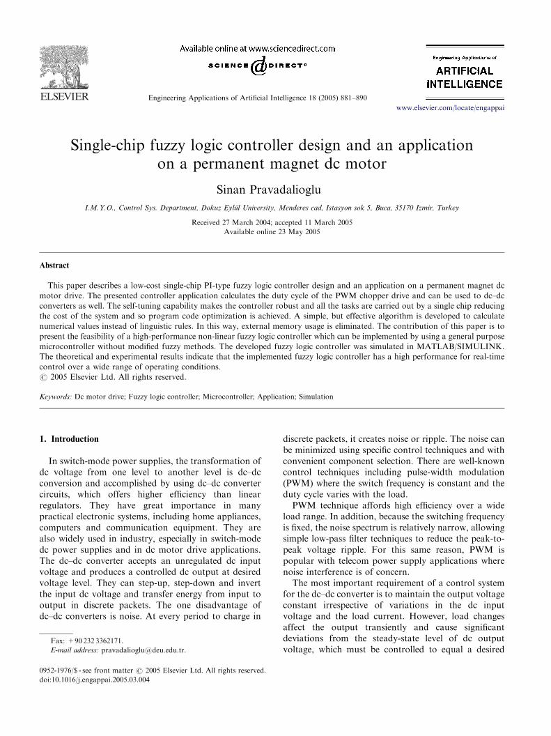
Here, yi represents the centroid of membershipfunction defining the ith rule output variable and canbe stored in a look-up table for quick acquisition.Membership functions for change of output of FLC,which is the duty cycle for this application, is shown inFig. 5.
ARTICLE IN PRESS
Fig. 5. Membership functions of change of output, the duty cycle.
Fig. 6. Control surface representation.
S. Pravadalioglu / Engineering Applications of Artificial Intelligence 18 (2005) 881–890 885
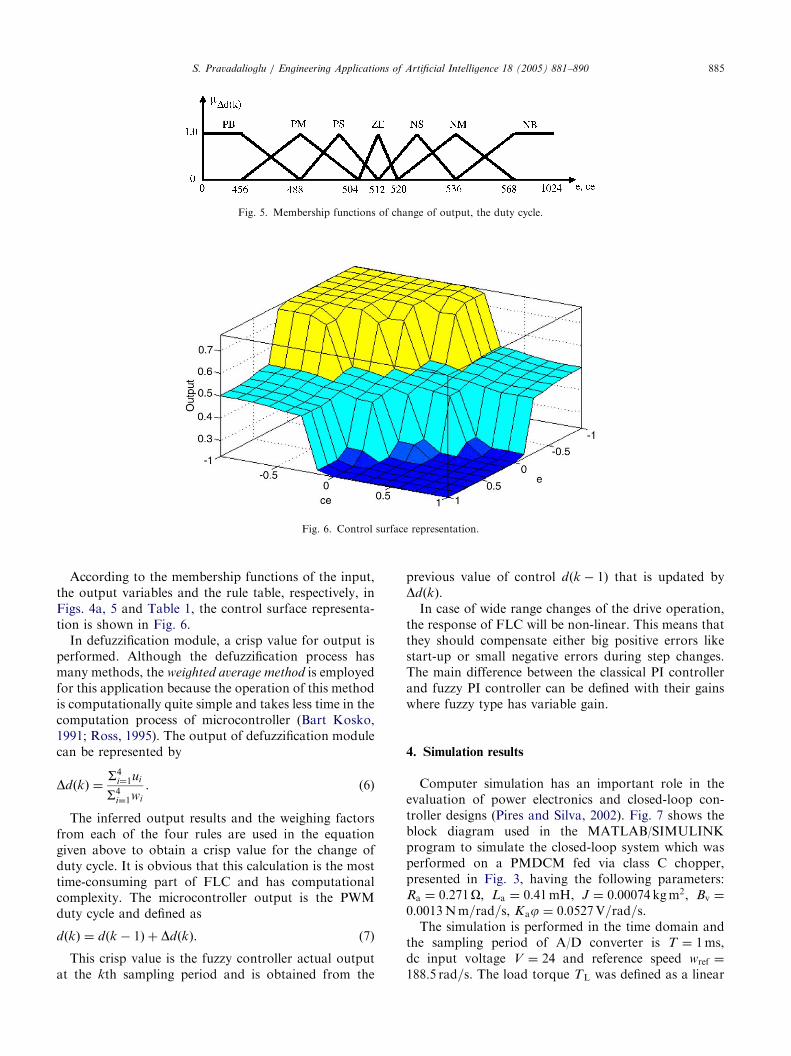
According to the membership functions of the input,the output variables and the rule table, respectively, inFigs. 4a, 5 and Table 1, the control surface representa-tion is shown in Fig. 6.
In defuzzification module, a crisp value for output isperformed. Although the defuzzification process hasmany methods, the weighted average method is employedfor this application because the operation of this methodis computationally quite simple and takes less time in thecomputation process of microcontroller (Bart Kosko,1991; Ross, 1995). The output of defuzzification modulecan be represented by
DdðkÞ ¼S4
i¼1ui
S4i¼1wi
. (6)
The inferred output results and the weighing factorsfrom each of the four rules are used in the equationgiven above to obtain a crisp value for the change ofduty cycle. It is obvious that this calculation is the mosttime-consuming part of FLC and has computationalcomplexity. The microcontroller output is the PWMduty cycle and defined as
dðkÞ ¼ dðk � 1Þ þ DdðkÞ. (7)
This crisp value is the fuzzy controller actual outputat the kth sampling period and is obtained from the
previous value of control dðk � 1Þ that is updated byDdðkÞ.
In case of wide range changes of the drive operation,the response of FLC will be non-linear. This means thatthey should compensate either big positive errors likestart-up or small negative errors during step changes.The main difference between the classical PI controllerand fuzzy PI controller can be defined with their gainswhere fuzzy type has variable gain.
4. Simulation results
Computer simulation has an important role in theevaluation of power electronics and closed-loop con-troller designs (Pires and Silva, 2002). Fig. 7 shows theblock diagram used in the MATLAB/SIMULINKprogram to simulate the closed-loop system which wasperformed on a PMDCM fed via class C chopper,presented in Fig. 3, having the following parameters:Ra ¼ 0:271O, La ¼ 0:41mH, J ¼ 0:00074 kgm2, Bv ¼
0:0013Nm=rad=s, Kaj ¼ 0:0527V=rad=s.The simulation is performed in the time domain and
the sampling period of A/D converter is T ¼ 1ms,dc input voltage V ¼ 24 and reference speed wref ¼
188:5 rad=s. The load torque TL was defined as a linear

ARTICLE IN PRESS
Fig. 7. Block diagram of the PMDCM motor drive with FLC in MATLAB/SIMULINK.
Fig. 8. Variation of speed (upper trace) and armature current (lower trace).
S. Pravadalioglu / Engineering Applications of Artificial Intelligence 18 (2005) 881–890886
function of rotor speed wr having the operating point(TL ¼ 0:26Nm, wr ¼ 188:5 rad=s). KE1 in the blockdiagram given in Fig. 7 is the gain of tacho-generator,W ref1 and W ref , which are the step functions to changethe sign of change of error in first sampling. The blockof signal generator supplies 2 kHz sawtooth waveformhaving the magnitude of one; hence, the control signalgenerated by the FLC will be equal to the duty cycle ofthe gate signals applied to the power switches. Duringsimulation process when the change of error is
calculated, noise on output of the A/D converter hasappeared because change of error in time of 1ms is avery small value, so we have a problem of leastsignificant bit in the number. To eliminate this effect,additional gain blocks are introduced before the A/Dconverter block. So it is necessary to divide after A/Dconverter output and that is why KE and KCE areplaced in the configuration.
Fig. 8 shows the variation of actual rotor speed andarmature current in time, when the load torque is

ARTICLE IN PRESSS. Pravadalioglu / Engineering Applications of Artificial Intelligence 18 (2005) 881–890 887
increased by the amount of 0.17Nm at 0.4 s. The actualrotor speed deviates from the reference speed and comesback to the reference after transients are damped out.The increase of armature current is the response toincrease of load torque.
5. Hardware and software designs
The hardware setup for the proposed fuzzy logicalgorithm was implemented in assembly programming,using 8-bit RISC (Reduced Instruction Set Computing)core microcontroller AT90S8535. A schematic diagramof the FLC with one of the Insulated Gate BipolarTransistor (IGBT) drive circuits of Class C chopper isshown in Fig. 9. The microcontroller has 8K bytes ofprogrammable flash memory, 512 bytes of internalrandom access memory, 8 channel 10 bit ADC, 10 bitPWM output, 16 different interrupt sources, an analog
Fig. 9. Schematic diagram of the FLC with I
comparator, 32 programmable I/O lines, a bi-directionalserial interface and has the ability to execute assemblerinstructions in a single clock cycle. The processing speedis one million instructions per megahertz crystal (AtmelCorporation).
The universe of discourse for error and change oferror are extended from �1024 to +1024 and the gradesof each membership function (0–1) are also extendedfrom 0 to 1024. In order to classify the fuzzy controllerinputs, eðkÞ and ceðkÞ, into seven fuzzy sets and todetermine their memberships, 10 bit mathematicalroutines are used. Therefore, processing the on-chip 10bit A/D converter sampling values and setting up theon-chip 10 bit PWM output for semiconductor switchesare directly achieved. As a result, the total systemresolution is extended to 1/1024 instead of 1/256 andbetter performance is obtained.
The symmetrical and 50% overlapped triangularmembership functions of eðkÞ and ceðkÞ simplify the
GBT drive circuit of Class C chopper.

ARTICLE IN PRESS
Fig. 10. Flow chart of the interrupt routine.
S. Pravadalioglu / Engineering Applications of Artificial Intelligence 18 (2005) 881–890888
calculations and its negative side is a reflection of thepositive. The fuzzy subset linguistic rule table given inTable 1 is changed to integer numbers in order to suitassembly programming. A simple but effective algo-rithm is designed for the appropriate numerical values ofconverted linguistic rules. This is realized with thefollowing equation according to calculated error values.The most important difference between the presentpaper and the papers cited in the references, is thedeveloped algorithm for fast calculation.
For error membership function,
e ¼ Xmin þ sTg; (8)
where e is the error value, Xmin ¼ �1024 is theminimum value of the control variable as shown inFig. 4a, s is the section number, starting from 0 to 6 forrepresenting seven fuzzy subsets of error membershipand Tg the width of every triangular membershipfunction, here it is 256.
For instance, let wref ¼ 1000 rpm and wact ¼ 650 rpm.The calculation of error according to Eq. (2) is eðkÞ ¼
350 rpm at a point x shown in Fig. 4b and from Eq. (8),
s ¼ 5:36719 (9)
is calculated. This value should be classified into fifthfuzzy set. It is well known that every eðkÞ belongs to atmost two fuzzy sets. Therefore, the above error valuehas two overlapping fuzzy sets, fifth and sixth which areprevailed to linguistic PS and PM as shown in Fig. 4b.The fraction part of s always belongs to the membershipfunction which has a positive slope. Therefore, for thisexample, the membership grade at point b shown in Fig.4b is
mpmðeÞ ¼ 0:36719.
The sum of membership grades of two symmetricaland 50% overlapped triangular fuzzy sets is alwaysequal to 1.0
mpmðeÞ þ mpsðeÞ ¼ 1:0.
Hence the membership grade at point a is
mpsðeÞ ¼ 1:0� 0:36719 ¼ 0:63281.
At the kth sampling time, change of error membershipfunction is also evaluated using the same Eq. (8). Thecalculated values of fuzzy variables are used in thedecision-making process. The flow chart of implementedassembler program is shown in Fig. 10.
Membership functions of the output duty cycle forapplication on a PMDCM drive is presented in Fig. 5. Atable is created for defuzzification process and stored asa look-up table containing the mean values of thesemembership functions of output and are used accordingto the weighted average method for defuzzification. Theweighted average method for the defuzzification has anadvantage over the other techniques in the case of
limited memory structure of RISC core microcontrol-lers. A crisp value for the change of duty cycle iscalculated from Eq. (6). According to Eq. (7) and thechange of output of FLC shown in Fig. 5, the calculatedchange of the duty cycle is used to determine the newduty cycle for the application,
dðkÞ ¼ dðk � 1Þ þ ½512� DdðkÞ. (10)
The calculated value is used to update the PWMoutput by an interrupt routine shown in Fig. 10 at every1ms (milli-second). Tests have shown that realizationof the mentioned fuzzy interrupt routine lasts 450 ms(micro-second) processing time with 4MHz clockfrequency. In this implementation, a D/A converter,

ARTICLE IN PRESSS. Pravadalioglu / Engineering Applications of Artificial Intelligence 18 (2005) 881–890 889
which might be needed for output variable is eliminatedby directly controlling the on–off periods of semicon-ductor switches via the on-chip PWM generator. Whenthe motor is started from standstill, the error and changeof error are estimated as positive at first sampling ofrotor speed since their initial value at standstill are takento be zero. The trend of change of error from standstillto steady state of rotor speed is negative; therefore, bychanging the sign of change of error from positiveestimated at first sampling to negative reduces thesettling time of the rotor speed.
6. Results
Another identical machine was coupled to the motorvia their shafts and operated as a generator for loading.Two different loading conditions were applied on themotor. In the first loading condition, the generatorterminals were closed to the resistive load of 2O and, therotor speed and armature current variations in timeduring this loading case were recorded. These results aregiven in Fig. 11a (Upper trace: 1V/div., Lower trace:0.2V/div. and 100mV/A. Time base: 200ms/div.). In the
Fig. 11. Experimental results: (a) speed and armature current versus
time; (b) speed and load current versus time.
second loading condition, the resistance of 2O wasconnected to the generator terminals while the rotor isrunning at reference speed. After the transients weredamped out, the resistor was disconnected. The varia-tions of actual rotor speed and generator output currentduring this case were recorded and are given in Fig. 11b(Upper trace: 1V/div., Lower trace: 0.2V/div. and100mV/A, Time base: 500ms/div.). It can be observedfrom the waveforms that the fuzzy logic controllerresponds to the step change on the load properly andbrings the actual rotor speed back to the referencespeed.
7. Conclusion
Fuzzy logic controller is implemented without mod-ified methods by using a general purpose low-costmicrocontroller for the speed control of a PMDCM. Allthe tasks are carried out by a single chip reducing thecost of the system and program code optimization isachieved with developed effective algorithm. In ourapproach, the software-based decision table is used andonly simple computations required in the on-line controlof an FLC; therefore, higher sampling rate can berealized more easily when comparing with other type ofcontrol schemes. The developed fuzzy logic controllerwas simulated in MATLAB/SIMULINK. Simulationand experimental results are compared in order to showthe response of the FLC under loading conditions. Itcan be found that the experimental results are very closeto the simulation results. The rise and settling times arereasonably smaller and there is no significant overshooton the experimental results. The effect of saturation isnot included into the motor and generator models;therefore, the simulation results deviate from theexperimental results within a small percentage duringloading transients. The experiments indicate that theimplemented fuzzy controller has a high performancefor real time control over a wide range of operatingconditions.
References
Atmel Corporation. http://www.atmel.com. AVR RISC datasheets,
application notes, tools.
Bart Kosko, 1991. Neural Networks and Fuzzy Systems. Prentice-
Hall, New York.
Brandsetter, P., Sedlak, P., 1996. Fuzzy control of electric drive using
DSP, PEMC’96, Budapest, Hungary, pp. 3/462–3/466.
Gupta, T., Boudreaux, R.R., Nelms, R.M., Hung, J.Y., 1997.
Implementation of a fuzzy controller for DC–DC converter using
an inexpensive 8-b Microcontroller. IEEE Transactions on
Industrial Electronics 44 (5).
Hyo, S.Park, Hee, J.Kim., 2001. Simultaneous control of buck and
boost DC–DC converter by fuzzy controller. ISIE 2001 Proceed-
ings, Pusan, Korea, pp. 1021–1025.

ARTICLE IN PRESSS. Pravadalioglu / Engineering Applications of Artificial Intelligence 18 (2005) 881–890890
Jan Jantsen, 1998. Design of Fuzzy Controllers, Technical Uni-
versity of Denmark, Department of Automation, Pub. No: 98-E-
864.
Lee, C.C., 1990. Fuzzy logic in control systems: fuzzy logic controller.
Part I, II. IEEE Transactions on Systems Man and Cybernetics 20
(2), 404–435.
Mattavelli, P., Rossetto, L., Spiazzi, G., Tenti, P., 1997. General
purpose fuzzy controller for DC–DC converters. IEEE Transac-
tions on Power Electronics 12 (1).
Pires, V.F., Silva, J.F.A., 2002. Teaching nonlinear modeling,
simulation, and control of electronic power converters using
MATLAB/SIMULINK. IEEE Transactions on Education 45 (3).
Ross, T.J., 1995. Fuzzy Logic with Engineering Applications.
McGraw-Hill, New York.
So, W.C., Tse, C.K., Lee, Y.S., 1995. An experimental fuzzy controller
for DC–DC converters. IEEE Power Electronics Specialist Con-
ference Record. pp. 1339–1345.
So, W.C., Tse, C.K., Lee, Y.S., 1996. Development of a fuzzy logic
controller for DC/DC converters: design, computer simulation and
experimental evaluation. IEEE Transactions on Power Electronics
11, 1.
Vas, P., 1998. Sensorless Vector and Direct Torque Control. Oxford
University Press, Oxford.
Vas, P., 1999. Artificial Intelligence Based Electrical Machines and
Drives. Oxford University Press, New York.
Zakharov, A., 1996. Investigation of dc servo drive with fuzzy logic
control. M.Sc. Thesis, Technical University of Budapest, Depart-
ment of Electrical Machines and Drives.


![Chapter 3: Fuzzy Rules & Fuzzy Reasoning513].pdf · CH. 3: Fuzzy rules & fuzzy reasoning 1 Chapter 3: Fuzzy Rules & Fuzzy Reasoning ... Application of the extension principle to fuzzy](https://img.pdfslide.us/doc/110x75/5b3ed7b37f8b9a3a138b5aa0/chapter-3-fuzzy-rules-fuzzy-513pdf-ch-3-fuzzy-rules-fuzzy-reasoning.jpg)