Embed Size (px)
Citation preview
5578 IEEE TRANSACTIONS ON POWER ELECTRONICS, VOL. 28, NO. 12, DECEMBER 2013
Single-Bus Star-Connected SwitchedReluctance Drive
Pourya Shamsi, Student Member, IEEE, and Babak Fahimi, Senior Member, IEEE
Abstract—Switched reluctance machines provide a feasible so-lution for automotive applications. However, a small and low costpower electronics driver is of interest for this purpose. This pa-per presents a control algorithm for a single-bus star-connectedswitched reluctance drive system. This algorithm enables the con-ventional Miller topology to control the phase currents in the mul-tiphase excitation mode of operation. This control algorithm isintroduced for motoring and generating modes of operation. Theintroduced algorithm is simulated under motoring and generatingmodes. Afterward, experimental measurements are illustrated toprove the practicality of the proposed concept.
Index Terms—Miller topology, single-bus star-connected swit-ched reluctance (SB-SC-SR) drive, single-bus SR-drive, star-connected SR-drive, switched reluctance drive.
I. INTRODUCTION
TRANSPORTATION systems are an integral part of anindustrial society. By providing mobility, transportation
systems enable for trading goods and bring convenience forusers. These systems require energy to operate. The increasein the population has resulted in more energy consumption bytransportation systems. The cause for a cleaner environmentand conservation of energy sources has led to integration ofmore electric vehicles (EVs) in the transportation systems. Thishas been accomplished by introducing hybrid electric vehicles(HEV) and EVs. Currently, the majority of the HEVs is utilizingpermanent magnet motor drives for propulsion. This is due tothe high torque density of these machines which is a result of thefield created by the permanent magnets. However, the increasingdemand for rare earth materials used in manufacturing of highenergy magnets leads to a shortage of these elements for thefuture generations. Therefore, introducing new types of motorswith limited or no use of permanent magnets for automotiveapplications is of interest.
Recently, application of a variety of electrical motors in hy-brid vehicles have been studied [1]. These studies range fromconventional induction machines to special machines such abrush-less dc machines [2]. However, recent studies suggest that
Manuscript received October 31, 2012; revised January 9, 2013; acceptedFebruary 25, 2013. Date of current version June 6, 2013. Recommended forpublication by Associate Editor S. Wirasingha.
The authors are with the Department of Electrical and Computer Engineering,University of Texas at Dallas, Dallas, TX 75080 USA (e-mail: [email protected]; [email protected]).
Color versions of one or more of the figures in this paper are available onlineat http://ieeexplore.ieee.org.
Digital Object Identifier 10.1109/TPEL.2013.2251475
switched reluctance machine (SRM) can be a promising choicefor the next generation of HEVs [1], [3], [4]. Unfortunately, dueto the magnetic structure of SRMs, a more complicated form ofpower electronic drive system is required in comparison withthe conventional permanent magnet or induction machines.
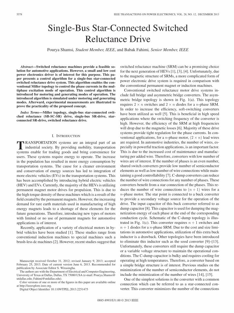
Conventional switched reluctance motor drive systems in-clude full bridge and asymmetric bridge converters. The asym-metric bridge topology is shown in Fig. 1(a). This topologyrequires 2 × n switches and 2 × n diodes for a n-phase SRM.In order to increase the efficiency, soft-switching convertershave been utilized as well [5]. This is beneficial in high speedapplications where the switching frequency of the converter ishigh. However, the efficiency of the SRM at high frequencieswill drop due to the magnetic losses [6]. Majority of these drivesystems provide tight regulation for the phase currents. In con-ventional applications, for a n-phase motor, (2 × n) lead wiresare required. In automotive industries, the number of wires, es-pecially in powerful traction applications, is an important factor.This is due to the increased cost of maintenance and manufac-turing per added wire. Therefore, converters with low number ofwires are of interest. If the number of phases is an even number,shared switch converters provide low number of semiconductorelements as well as low number of wire connections while main-taining a good controllability [7]. C-dump converters can reducethe number of wire connections for any number of phases. Theseconverters benefit from a star connection of the phases. This re-duces the number of wire connections to (n + 1) wires for an-phase motor. The star point is connected to a buck converterto provide a secondary voltage source for the operation of thedrive. The input capacitor of this buck converter referred to asdump capacitor [8]. This capacitor is used for dumping the mag-netization energy of each phase at the end of the correspondingconduction cycle. Schematic of the C-dump topology is illus-trated in Fig. 1(c). This converter requires n + 1 switches andn + 1 diodes for a n-phase SRM. Due to the cost and size limi-tations in automotive applications, utilization of this extra buckinductor is a drawback. Other topologies have been introducedto eliminate this inductor such as the sood converter [9]–[13].Unfortunately, these converters still require the dump capacitoror a variable voltage structure to maintain the operational con-ditions. The C-dump capacitor is bulky and requires cooling foroperating at high temperatures. Therefore, a converter based ona simple bridge structure is of interest. Previous studies on theminimization of the number of semiconductor elements, do notinclude the minimization of the number of wires [14], [15].
One of the simplest solutions is the converter with a commonconnection which can be referred to as a star-connected con-verter. This converter minimizes the number of the connections
0885-8993/$31.00 © 2013 IEEE
SHAMSI AND FAHIMI: SINGLE-BUS STAR-CONNECTED SWITCHED RELUCTANCE DRIVE 5579
Fig. 1. Schematics of different topologies. (a) Asymmetric bridge. (b) Shared switch. (c) C-dump converter. (d) Single-bus star-connected topology (Miller).
as well as the number of the semiconductor switches or diodes to(n + 1) for a n-phase motor. This topology is shown in Fig. 1(d).This converter has been introduced as the Miller converter inthe literature [16], [17]. However, the Miller converter has beenknown to be hard-to-control due to the interference between thephases in a multiphase excitation mode of operation [18]. In thispaper, a switching pattern generating algorithm for the Millerconverter is introduced. This control algorithm is based on pri-oritizing the control command based on the rotor angle. Thiscontrol method enables the Miller converter to operate in themultiphase excitation mode of operation. After introduction ofthe Miller converter, the control algorithm is introduced in theSection III. Simulation and experimental results are provided tovalidate the proposed algorithm.
II. CIRCUIT TOPOLOGY
A single-bus star-connected (SB-SC) converter (i.e., Millerconverter) is shown in Fig. 1(d). This converter benefits forma star connection for the motor phases. This reduces the re-quired number of lead wires to (n + 1). Moreover, only (n + 1)switches and (n + 1) diodes are utilized. Therefore, this topol-ogy reduces the number of the wires and semiconductor switchessimultaneously. These features make this converter a suitablechoice for automotive applications.
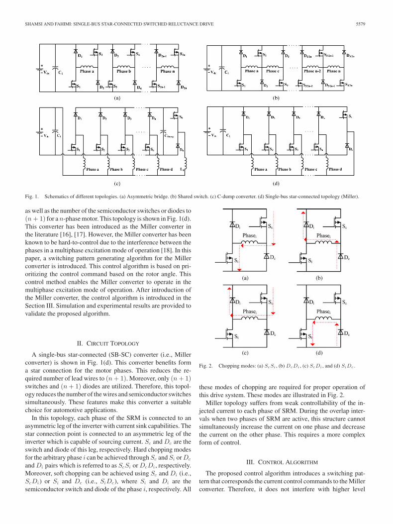
In this topology, each phase of the SRM is connected to anasymmetric leg of the inverter with current sink capabilities. Thestar connection point is connected to an asymmetric leg of theinverter which is capable of sourcing current. Sc and Dc are theswitch and diode of this leg, respectively. Hard chopping modesfor the arbitrary phase i can be achieved through Sc and Si or Dc
and Di pairs which is referred to as ScSi or DcDi , respectively.Moreover, soft chopping can be achieved using Sc and Di (i.e.,ScDi) or Si and Dc (i.e., SiDc ), where Si and Di are thesemiconductor switch and diode of the phase i, respectively. All
Fig. 2. Chopping modes: (a) Sc Si , (b) Dc Di , (c) Sc Di , and (d) SiDc .
these modes of chopping are required for proper operation ofthis drive system. These modes are illustrated in Fig. 2.
Miller topology suffers from weak controllability of the in-jected current to each phase of SRM. During the overlap inter-vals when two phases of SRM are active, this structure cannotsimultaneously increase the current on one phase and decreasethe current on the other phase. This requires a more complexform of control.
III. CONTROL ALGORITHM
The proposed control algorithm introduces a switching pat-tern that corresponds the current control commands to the Millerconverter. Therefore, it does not interfere with higher level
5580 IEEE TRANSACTIONS ON POWER ELECTRONICS, VOL. 28, NO. 12, DECEMBER 2013
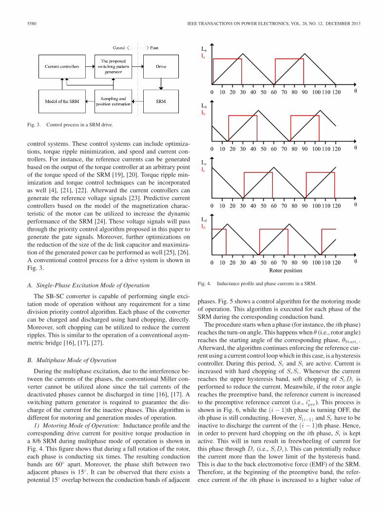
Fig. 3. Control process in a SRM drive.
control systems. These control systems can include optimiza-tions, torque ripple minimization, and speed and current con-trollers. For instance, the reference currents can be generatedbased on the output of the torque controller at an arbitrary pointof the torque speed of the SRM [19], [20]. Torque ripple min-imization and torque control techniques can be incorporatedas well [4], [21], [22]. Afterward the current controllers cangenerate the reference voltage signals [23]. Predictive currentcontrollers based on the model of the magnetization charac-teristic of the motor can be utilized to increase the dynamicperformance of the SRM [24]. These voltage signals will passthrough the priority control algorithm proposed in this paper togenerate the gate signals. Moreover, further optimizations onthe reduction of the size of the dc link capacitor and maximiza-tion of the generated power can be performed as well [25], [26].A conventional control process for a drive system is shown inFig. 3.
A. Single-Phase Excitation Mode of Operation
The SB-SC converter is capable of performing single exci-tation mode of operation without any requirement for a timedivision priority control algorithm. Each phase of the convertercan be charged and discharged using hard chopping, directly.Moreover, soft chopping can be utilized to reduce the currentripples. This is similar to the operation of a conventional asym-metric bridge [16], [17], [27].
B. Multiphase Mode of Operation
During the multiphase excitation, due to the interference be-tween the currents of the phases, the conventional Miller con-verter cannot be utilized alone since the tail currents of thedeactivated phases cannot be discharged in time [16], [17]. Aswitching pattern generator is required to guarantee the dis-charge of the current for the inactive phases. This algorithm isdifferent for motoring and generation modes of operation.
1) Motoring Mode of Operation: Inductance profile and thecorresponding drive current for positive torque production ina 8/6 SRM during multiphase mode of operation is shown inFig. 4. This figure shows that during a full rotation of the rotor,each phase is conducting six times. The resulting conductionbands are 60◦ apart. Moreover, the phase shift between twoadjacent phases is 15◦. It can be observed that there exists apotential 15◦ overlap between the conduction bands of adjacent
Fig. 4. Inductance profile and phase currents in a SRM.
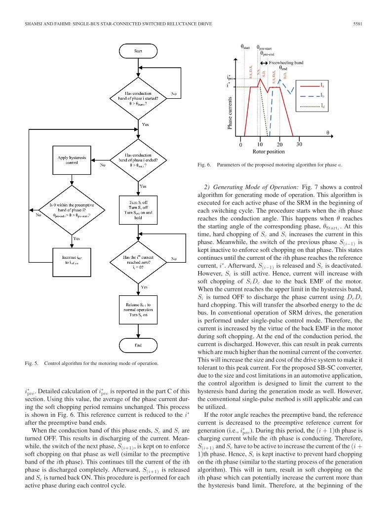
phases. Fig. 5 shows a control algorithm for the motoring modeof operation. This algorithm is executed for each phase of theSRM during the corresponding conduction band.
The procedure starts when a phase (for instance, the ith phase)reaches the turn-on angle. This happens when θ (i.e., rotor angle)reaches the starting angle of the corresponding phase, θStarti
.Afterward, the algorithm continues enforcing the reference cur-rent using a current control loop which in this case, is a hysteresiscontroller. During this period, Sc and Si are active. Current isincreased with hard chopping of ScSi . Whenever the currentreaches the upper hysteresis band, soft chopping of ScDi isperformed to reduce the current. Meanwhile, if the rotor anglereaches the preemptive band, the reference current is increasedto the preemptive reference current (i.e., i∗pre). This process isshown in Fig. 6, while the (i − 1)th phase is turning OFF, theith phase is still conducting. However, S(i−1) and Sc have to beinactive to discharge the current of the (i − 1)th phase. Hence,in order to prevent hard chopping on the ith phase, Si is keptactive. This will in turn result in freewheeling of current forthis phase through Dc (i.e., SiDc ). This can potentially reducethe current more than the lower limit of the hysteresis band.This is due to the back electromotive force (EMF) of the SRM.Therefore, at the beginning of the preemptive band, the refer-ence current of the ith phase is increased to a higher value of
SHAMSI AND FAHIMI: SINGLE-BUS STAR-CONNECTED SWITCHED RELUCTANCE DRIVE 5581
Fig. 5. Control algorithm for the motoring mode of operation.
i∗pre . Detailed calculation of i∗pre is reported in the part C of thissection. Using this value, the average of the phase current dur-ing the soft chopping period remains unchanged. This processis shown in Fig. 6. This reference current is reduced to the i∗
after the preemptive band ends.When the conduction band of this phase ends, Sc and Si are
turned OFF. This results in discharging of the current. Mean-while, the switch of the next phase, S(i+1) , is kept on to enforcesoft chopping on that phase as well (similar to the preemptiveband of the ith phase). This continues till the current of the ithphase is discharged completely. Afterward, S(i+1) is releasedand Sc is turned back ON. This procedure is performed for eachactive phase during each control cycle.
Fig. 6. Parameters of the proposed motoring algorithm for phase a.
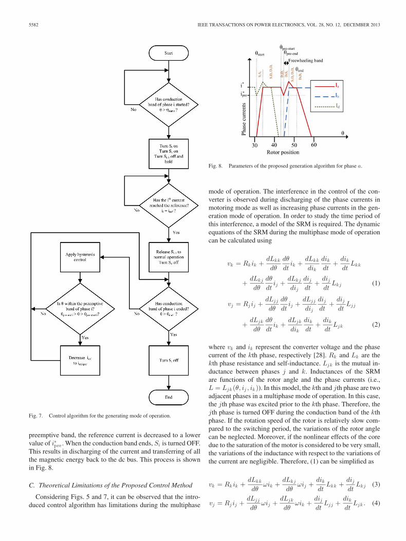
2) Generating Mode of Operation: Fig. 7 shows a controlalgorithm for generating mode of operation. This algorithm isexecuted for each active phase of the SRM in the beginning ofeach switching cycle. The procedure starts when the ith phasereaches the conduction angle. This happens when θ reachesthe starting angle of the corresponding phase, θStarti
. At thistime, hard chopping of Sc and Si increases the current in thisphase. Meanwhile, the switch of the previous phase S(i−1) iskept inactive to enforce soft chopping on that phase. This statescontinues until the current of the ith phase reaches the referencecurrent, i∗. Afterward, S(i−1) is released and Sc is deactivated.However, Si is still active. Hence, current will increase withsoft chopping of SiDc due to the back EMF of the motor.When the current reaches the upper limit in the hysteresis band,Si is turned OFF to discharge the phase current using DcDi
hard chopping. This will transfer the absorbed energy to the dcbus. In conventional operation of SRM drives, the generationis performed under single-pulse control mode. Therefore, thecurrent is increased by the virtue of the back EMF in the motorduring soft chopping. At the end of the conduction period, thecurrent is discharged. However, this can result in peak currentswhich are much higher than the nominal current of the converter.This will increase the size and cost of the drive system to make ittolerant to this peak current. For the proposed SB-SC converter,due to the size and cost limitations in an automotive application,the control algorithm is designed to limit the current to thehysteresis band during the generation mode as well. However,the conventional single-pulse method is still applicable and canbe utilized.
If the rotor angle reaches the preemptive band, the referencecurrent is decreased to the preemptive reference current forgeneration (i.e., i∗pre). During this period, the (i + 1)th phase ischarging current while the ith phase is conducting. Therefore,S(i+1) and Sc have to be active to increase the current of the (i +1)th phase. Hence, Si is kept inactive to prevent hard choppingon the ith phase (similar to the starting process of the generationalgorithm). This will in turn, result in soft chopping on theith phase which can potentially increase the current more thanthe hysteresis band limit. Therefore, at the beginning of the
5582 IEEE TRANSACTIONS ON POWER ELECTRONICS, VOL. 28, NO. 12, DECEMBER 2013
Fig. 7. Control algorithm for the generating mode of operation.
preemptive band, the reference current is decreased to a lowervalue of i∗pre . When the conduction band ends, Si is turned OFF.This results in discharging of the current and transferring of allthe magnetic energy back to the dc bus. This process is shownin Fig. 8.
C. Theoretical Limitations of the Proposed Control Method
Considering Figs. 5 and 7, it can be observed that the intro-duced control algorithm has limitations during the multiphase
Fig. 8. Parameters of the proposed generation algorithm for phase a.
mode of operation. The interference in the control of the con-verter is observed during discharging of the phase currents inmotoring mode as well as increasing phase currents in the gen-eration mode of operation. In order to study the time period ofthis interference, a model of the SRM is required. The dynamicequations of the SRM during the multiphase mode of operationcan be calculated using
vk = Rkik +dLkk
dθ
dθ
dtik +
dLkk
dik
dikdt
+dikdt
Lkk
+dLkj
dθ
dθ
dtij +
dLkj
dij
dijdt
+dijdt
Lkj (1)
vj = Rj ij +dLjj
dθ
dθ
dtij +
dLjj
dij
dijdt
+dijdt
Ljj
+dLjk
dθ
dθ
dtik +
dLjk
dik
dikdt
+dikdt
Ljk (2)
where vk and ik represent the converter voltage and the phasecurrent of the kth phase, respectively [28]. Rk and Lk are thekth phase resistance and self-inductance. Ljk is the mutual in-ductance between phases j and k. Inductances of the SRMare functions of the rotor angle and the phase currents (i.e.,L = Ljk (θ, ij , ik )). In this model, the kth and jth phase are twoadjacent phases in a multiphase mode of operation. In this case,the jth phase was excited prior to the kth phase. Therefore, thejth phase is turned OFF during the conduction band of the kthphase. If the rotation speed of the rotor is relatively slow com-pared to the switching period, the variations of the rotor anglecan be neglected. Moreover, if the nonlinear effects of the coredue to the saturation of the motor is considered to be very small,the variations of the inductance with respect to the variations ofthe current are negligible. Therefore, (1) can be simplified as
vk = Rkik +dLkk
dθωik +
dLkj
dθωij +
dikdt
Lkk +dijdt
Lkj (3)
vj = Rj ij +dLjj
dθωij +
dLjk
dθωik +
dijdt
Ljj +dikdt
Ljk . (4)
SHAMSI AND FAHIMI: SINGLE-BUS STAR-CONNECTED SWITCHED RELUCTANCE DRIVE 5583
These dynamic equations can form the state space model of theactive phases as
x = Ax + Bu (5)
x = [ik ij ]T (6)
A11 =−RkLjj − ω(L′
kkθLjj − L′
jkθLkj )
LkkLjj − LjkLkj(7)
A12 =RjLkj + ω(L′
jjθLkj − L′
kjθLjj )
LkkLjj − LjkLkj(8)
A21 =RkLjk + ω(L′
kkθLjk − L′
jkθLkk )
LkkLjj − LjkLkj(9)
A22 =−RjLkk − ω(L′
jjθLkk − L′
kjθLjk )
LkkLjj − LjkLkj(10)
Bu =1
LkkLjj − LjkLkj
[Ljj −Lkj
−Ljk Lkk
] [vk
vj
](11)
where L′jkθ
is the derivative of the inductance with respect to
the rotor angle (i.e., dLjk/dθ). Moreover, ik is the derivative ofthe current with respect to time. During the discharge period, theapplied voltage of the converter to the jth phase is the negative ofthe dc bus (i.e., vj = −udc). During this period, the kth phase isunder soft chopping (i.e., vk = 0). Therefore, the phase currentsof the SRM during the discharge of the current from phase j canbe calculated as
Ik (s) =1
sF1(s){i∗pre(LkkLjj − Ljk
2)s2
+ vdcL′jkθ
ω + [(L′jjθ
(i∗preLkk + i∗Ljk )ω
− L′jkθ
(i∗preLjk + i∗Ljj ))ω + Ljkvdc
+ (i∗preLkk + i∗Ljk )Rj ]s} (12)
Ij (s) =1
sF1(s){i∗(LkkLjj − Ljk
2)s2
− vdc(L′kkθ
ω + Rk ) + [(L′kkθ
(i∗preLjk + i∗Ljj )ω
− L′jkθ
(i∗preLkk + i∗Ljk ))ω − Lkkvdc
+ (i∗preLjk + i∗Ljj )Rk ]s} (13)
where the characteristic function F1(s) can be calculated using
F1(s) = (LkkLjj − Ljk2)s2 + LjjRk + LkkRjs
+ (L′jjθ
Lkk + LL′kkθ
Ljj − 2L′jkθ
Ljk )ωs
+ (L′kkθ
L′jjθ
− (L′jkθ
)2)ω2 + RjRk
+ (L′jjθ
Rk + L′kkθ
Rj )ω. (14)
For this transformation, the initial conditions of the variablesare added to the Laplace transform. It can be assumed that thecurrent of phase k has reached the preemptive reference (i.e.,i∗pre) and current of the phase j is the reference current (i.e., i∗)prior to the discharge cycle.
Using these equations, the required time for discharging thecurrent can be calculated. This amount of time corresponds to
the minimum amount of turn-off angle required for discharg-ing the current before the generation mode starts. Moreover,the required preemptive reference, i∗pre , to keep the average ofthe current unchanged in the soft chopping phase (i.e., phase k)can be calculated using (12). The mutual inductances as com-pared to the self-inductances are small values. Moreover, (12)and (13) cannot be simplified further. However, if the mutualinductance between these phases in neglected, the equation canbe simplified as
Ik (s) =i∗preLkk
Lkks + L′kkθ
ω + Rk(15)
Ij (s) =i∗Ljj s − vdc
s(Ljj s + L′jjθ
ω + Rj )(16)
and the currents in the time domain can be calculated using
ik (t) = i∗preexp[−
L′kkθ
ω + Rk
Lkkt
](17)
ij (t) = i∗exp[−
L′jjθ
ω + Rj
Ljjt
]
+−vdc
L′jjθ
ω + Rj
(1 − exp
[−
L′jjθ
ω + Rj
Ljjt
]). (18)
Therefore, the required amount of time, and the required pre-emptive current can be calculated using
tdischarge =−Ljj
L′jjθ
ω + Rjln
(vdc
vdc + i∗(L′jjθ
ω + Rj )
)(19)
i∗pre =2i∗
1 + exp[−L′
kkθω + Rk
Lkktdischarge
] . (20)
During the discharge period of the phase j, the preemptive ref-erence can keep the average of the current of phase k constant.Hence, the required model to calculate the preemptive refer-ences is derived. Moreover, the model can be used to calculatethe required time necessary for the controller to charge anddischarge the phase currents.
D. Comparison of the SB-SC-SR DriveWith the Conventional Drives
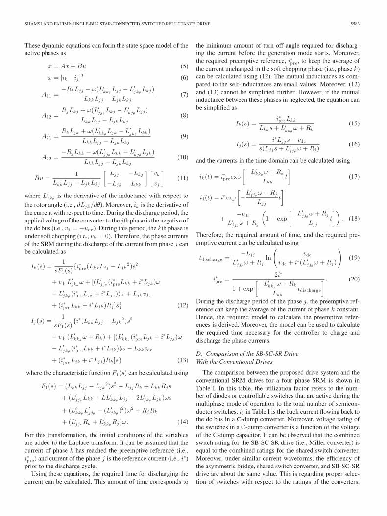
The comparison between the proposed drive system and theconventional SRM drives for a four phase SRM is shown inTable I. In this table, the utilization factor refers to the num-ber of diodes or controllable switches that are active during themultiphase mode of operation to the total number of semicon-ductor switches. ib in Table I is the buck current flowing back tothe dc bus in a C-dump converter. Moreover, voltage rating ofthe switches in a C-dump converter is a function of the voltageof the C-dump capacitor. It can be observed that the combinedswitch rating for the SB-SC-SR drive (i.e., Miller converter) isequal to the combined ratings for the shared switch converter.Moreover, under similar current waveforms, the efficiency ofthe asymmetric bridge, shared switch converter, and SB-SC-SRdrive are about the same value. This is regarding proper selec-tion of switches with respect to the ratings of the converters.
5584 IEEE TRANSACTIONS ON POWER ELECTRONICS, VOL. 28, NO. 12, DECEMBER 2013
TABLE ICOMPARISON BETWEEN THE SB-SC-SR AND CONVENTIONAL DRIVES
Fig. 9. Simulation results for the motoring mode of operation.
However, the C-dump converter has a lower efficiency due tothe power loss in the buck inductor.
IV. SIMULATION RESULTS
A simulation is performed on a four-phase SRM in order tostudy the proposed control algorithm. This algorithm is sim-ulated for both motoring and generating modes of operationduring a multiphase excitation condition.
A. Motoring Mode of Operation
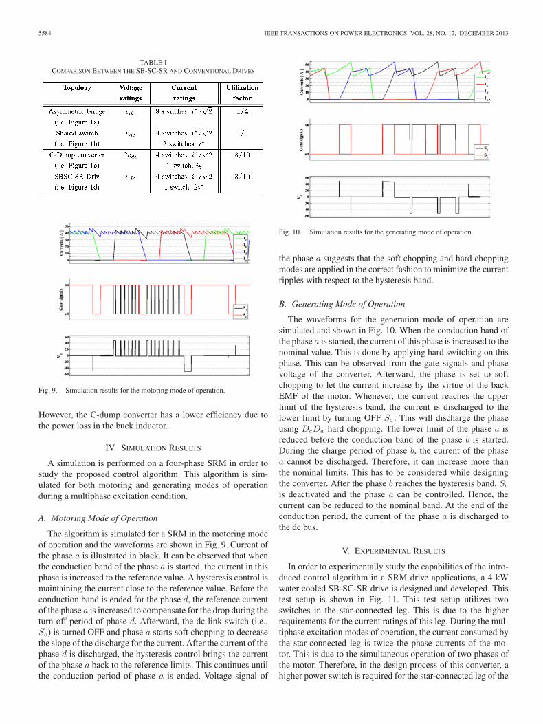
The algorithm is simulated for a SRM in the motoring modeof operation and the waveforms are shown in Fig. 9. Current ofthe phase a is illustrated in black. It can be observed that whenthe conduction band of the phase a is started, the current in thisphase is increased to the reference value. A hysteresis control ismaintaining the current close to the reference value. Before theconduction band is ended for the phase d, the reference currentof the phase a is increased to compensate for the drop during theturn-off period of phase d. Afterward, the dc link switch (i.e.,Sc ) is turned OFF and phase a starts soft chopping to decreasethe slope of the discharge for the current. After the current of thephase d is discharged, the hysteresis control brings the currentof the phase a back to the reference limits. This continues untilthe conduction period of phase a is ended. Voltage signal of
Fig. 10. Simulation results for the generating mode of operation.
the phase a suggests that the soft chopping and hard choppingmodes are applied in the correct fashion to minimize the currentripples with respect to the hysteresis band.
B. Generating Mode of Operation
The waveforms for the generation mode of operation aresimulated and shown in Fig. 10. When the conduction band ofthe phase a is started, the current of this phase is increased to thenominal value. This is done by applying hard switching on thisphase. This can be observed from the gate signals and phasevoltage of the converter. Afterward, the phase is set to softchopping to let the current increase by the virtue of the backEMF of the motor. Whenever, the current reaches the upperlimit of the hysteresis band, the current is discharged to thelower limit by turning OFF Sa . This will discharge the phaseusing DcDa hard chopping. The lower limit of the phase a isreduced before the conduction band of the phase b is started.During the charge period of phase b, the current of the phasea cannot be discharged. Therefore, it can increase more thanthe nominal limits. This has to be considered while designingthe converter. After the phase b reaches the hysteresis band, Sc
is deactivated and the phase a can be controlled. Hence, thecurrent can be reduced to the nominal band. At the end of theconduction period, the current of the phase a is discharged tothe dc bus.
V. EXPERIMENTAL RESULTS
In order to experimentally study the capabilities of the intro-duced control algorithm in a SRM drive applications, a 4 kWwater cooled SB-SC-SR drive is designed and developed. Thistest setup is shown in Fig. 11. This test setup utilizes twoswitches in the star-connected leg. This is due to the higherrequirements for the current ratings of this leg. During the mul-tiphase excitation modes of operation, the current consumed bythe star-connected leg is twice the phase currents of the mo-tor. This is due to the simultaneous operation of two phases ofthe motor. Therefore, in the design process of this converter, ahigher power switch is required for the star-connected leg of the
SHAMSI AND FAHIMI: SINGLE-BUS STAR-CONNECTED SWITCHED RELUCTANCE DRIVE 5585
Fig. 11. Experimental setup of the SB-SC-SR drive system.
converter. The star connection point of the motor wires is shownin Fig. 11. Moreover, a ZigBee wireless communication systemenables the remote monitoring and control of the drive system.
A. Motoring Mode of Operation
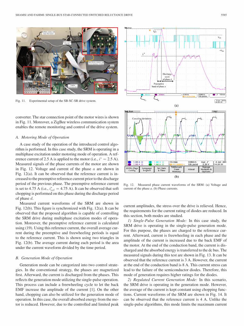
A case study of the operation of the introduced control algo-rithm is performed. In this case study, the SRM is operating in amultiphase excitation under motoring mode of operation. A ref-erence current of 2.5 A is applied to the motor (i.e., i∗ = 2.5 A).Measured signals of the phase currents of the motor are shownin Fig. 12. Voltage and current of the phase a are shown inFig. 12(a). It can be observed that the reference current is in-creased to the preemptive reference current prior to the dischargeperiod of the previous phase. The preemptive reference currentis set to 4.75 A (i.e., i∗ref = 4.75 A). It can be observed that softchopping is performed on this phase during the discharge periodof phase d.
Measured current waveforms of the SRM are shown inFig. 12(b). This figure is synchronized with Fig. 12(a). It can beobserved that the proposed algorithm is capable of controllingthe SRM drive during multiphase excitation modes of opera-tion. Moreover, the preemptive reference current is calculatedusing (19). Using this reference current, the overall average cur-rent during the preemptive and freewheeling periods is equalto the reference current. This is shown using two triangles inFig. 12(b). The average current during each period is the areaunder the current waveform divided by the time period.
B. Generation Mode of Operation
Generation mode can be categorized into two control strate-gies. In the conventional strategy, the phases are magnetizedfirst. Afterward, the current is discharged from the phases. Thisreflects the generation mode utilizing the single-pulse operation.This process can include a freewheeling cycle to let the backEMF increase the amplitude of the current [1]. On the otherhand, chopping can also be utilized for the generation mode ofoperation. In this case, the overall absorbed energy from the mo-tor is reduced. However, due to the controlled and limited peak
Fig. 12. Measured phase current waveforms of the SRM: (a) Voltage andcurrent of the phase a. (b) Phase currents.
current amplitudes, the stress over the drive is relieved. Hence,the requirements for the current rating of diodes are reduced. Inthis section, both modes are studied.
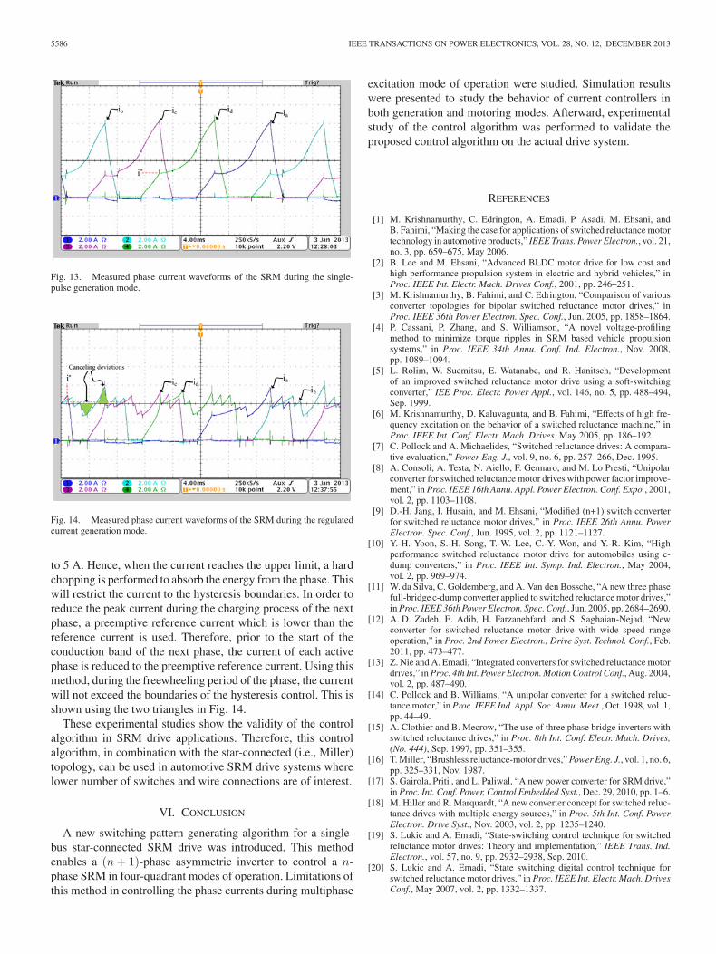
1) Single-Pulse Generation Mode: In this case study, theSRM drive is operating in the single-pulse generation mode.For this purpose, the phases are charged to the reference cur-rent. Afterward, current is freewheeling in each phase and theamplitude of the current is increased due to the back EMF ofthe motor. At the end of the conduction band, the current is dis-charged and the absorbed energy is transferred to the dc bus. Themeasured signals during this test are shown in Fig. 13. It can beobserved that the reference current is 3 A. However, the currentat the end of the conduction band is 8 A. This current stress canlead to the failure of the semiconductor diodes. Therefore, thismode of generation requires higher ratings for the diodes.
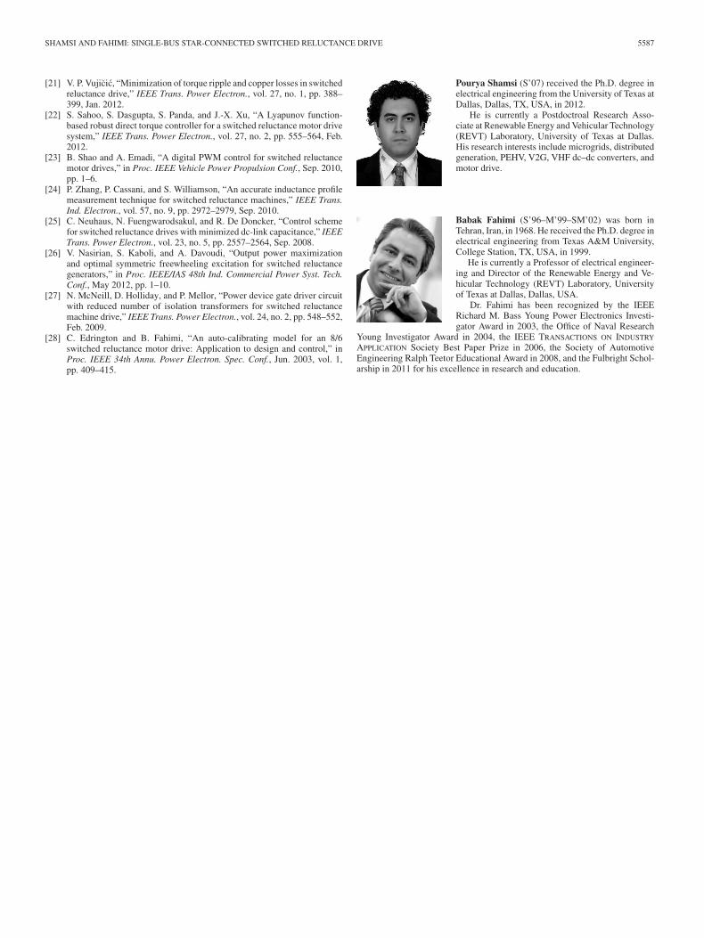
2) Regulated Current Generation Mode: In this scenario,the SRM drive is operating in the generation mode. However,the average of the current is kept constant using chopping func-tions. Current waveforms of the SRM are shown in Fig. 14. Itcan be observed that the reference current is 4 A. Unlike thesingle-pulse algorithms, this mode limits the maximum current
5586 IEEE TRANSACTIONS ON POWER ELECTRONICS, VOL. 28, NO. 12, DECEMBER 2013
Fig. 13. Measured phase current waveforms of the SRM during the single-pulse generation mode.
Fig. 14. Measured phase current waveforms of the SRM during the regulatedcurrent generation mode.
to 5 A. Hence, when the current reaches the upper limit, a hardchopping is performed to absorb the energy from the phase. Thiswill restrict the current to the hysteresis boundaries. In order toreduce the peak current during the charging process of the nextphase, a preemptive reference current which is lower than thereference current is used. Therefore, prior to the start of theconduction band of the next phase, the current of each activephase is reduced to the preemptive reference current. Using thismethod, during the freewheeling period of the phase, the currentwill not exceed the boundaries of the hysteresis control. This isshown using the two triangles in Fig. 14.
These experimental studies show the validity of the controlalgorithm in SRM drive applications. Therefore, this controlalgorithm, in combination with the star-connected (i.e., Miller)topology, can be used in automotive SRM drive systems wherelower number of switches and wire connections are of interest.
VI. CONCLUSION
A new switching pattern generating algorithm for a single-bus star-connected SRM drive was introduced. This methodenables a (n + 1)-phase asymmetric inverter to control a n-phase SRM in four-quadrant modes of operation. Limitations ofthis method in controlling the phase currents during multiphase
excitation mode of operation were studied. Simulation resultswere presented to study the behavior of current controllers inboth generation and motoring modes. Afterward, experimentalstudy of the control algorithm was performed to validate theproposed control algorithm on the actual drive system.
REFERENCES
[1] M. Krishnamurthy, C. Edrington, A. Emadi, P. Asadi, M. Ehsani, andB. Fahimi, “Making the case for applications of switched reluctance motortechnology in automotive products,” IEEE Trans. Power Electron., vol. 21,no. 3, pp. 659–675, May 2006.
[2] B. Lee and M. Ehsani, “Advanced BLDC motor drive for low cost andhigh performance propulsion system in electric and hybrid vehicles,” inProc. IEEE Int. Electr. Mach. Drives Conf., 2001, pp. 246–251.
[3] M. Krishnamurthy, B. Fahimi, and C. Edrington, “Comparison of variousconverter topologies for bipolar switched reluctance motor drives,” inProc. IEEE 36th Power Electron. Spec. Conf., Jun. 2005, pp. 1858–1864.
[4] P. Cassani, P. Zhang, and S. Williamson, “A novel voltage-profilingmethod to minimize torque ripples in SRM based vehicle propulsionsystems,” in Proc. IEEE 34th Annu. Conf. Ind. Electron., Nov. 2008,pp. 1089–1094.
[5] L. Rolim, W. Suemitsu, E. Watanabe, and R. Hanitsch, “Developmentof an improved switched reluctance motor drive using a soft-switchingconverter,” IEE Proc. Electr. Power Appl., vol. 146, no. 5, pp. 488–494,Sep. 1999.
[6] M. Krishnamurthy, D. Kaluvagunta, and B. Fahimi, “Effects of high fre-quency excitation on the behavior of a switched reluctance machine,” inProc. IEEE Int. Conf. Electr. Mach. Drives, May 2005, pp. 186–192.
[7] C. Pollock and A. Michaelides, “Switched reluctance drives: A compara-tive evaluation,” Power Eng. J., vol. 9, no. 6, pp. 257–266, Dec. 1995.
[8] A. Consoli, A. Testa, N. Aiello, F. Gennaro, and M. Lo Presti, “Unipolarconverter for switched reluctance motor drives with power factor improve-ment,” in Proc. IEEE 16th Annu. Appl. Power Electron. Conf. Expo., 2001,vol. 2, pp. 1103–1108.
[9] D.-H. Jang, I. Husain, and M. Ehsani, “Modified (n+1) switch converterfor switched reluctance motor drives,” in Proc. IEEE 26th Annu. PowerElectron. Spec. Conf., Jun. 1995, vol. 2, pp. 1121–1127.
[10] Y.-H. Yoon, S.-H. Song, T.-W. Lee, C.-Y. Won, and Y.-R. Kim, “Highperformance switched reluctance motor drive for automobiles using c-dump converters,” in Proc. IEEE Int. Symp. Ind. Electron., May 2004,vol. 2, pp. 969–974.
[11] W. da Silva, C. Goldemberg, and A. Van den Bossche, “A new three phasefull-bridge c-dump converter applied to switched reluctance motor drives,”in Proc. IEEE 36th Power Electron. Spec. Conf., Jun. 2005, pp. 2684–2690.
[12] A. D. Zadeh, E. Adib, H. Farzanehfard, and S. Saghaian-Nejad, “Newconverter for switched reluctance motor drive with wide speed rangeoperation,” in Proc. 2nd Power Electron., Drive Syst. Technol. Conf., Feb.2011, pp. 473–477.
[13] Z. Nie and A. Emadi, “Integrated converters for switched reluctance motordrives,” in Proc. 4th Int. Power Electron. Motion Control Conf., Aug. 2004,vol. 2, pp. 487–490.
[14] C. Pollock and B. Williams, “A unipolar converter for a switched reluc-tance motor,” in Proc. IEEE Ind. Appl. Soc. Annu. Meet., Oct. 1998, vol. 1,pp. 44–49.
[15] A. Clothier and B. Mecrow, “The use of three phase bridge inverters withswitched reluctance drives,” in Proc. 8th Int. Conf. Electr. Mach. Drives,(No. 444), Sep. 1997, pp. 351–355.
[16] T. Miller, “Brushless reluctance-motor drives,” Power Eng. J., vol. 1, no. 6,pp. 325–331, Nov. 1987.
[17] S. Gairola, Priti , and L. Paliwal, “A new power converter for SRM drive,”in Proc. Int. Conf. Power, Control Embedded Syst., Dec. 29, 2010, pp. 1–6.
[18] M. Hiller and R. Marquardt, “A new converter concept for switched reluc-tance drives with multiple energy sources,” in Proc. 5th Int. Conf. PowerElectron. Drive Syst., Nov. 2003, vol. 2, pp. 1235–1240.
[19] S. Lukic and A. Emadi, “State-switching control technique for switchedreluctance motor drives: Theory and implementation,” IEEE Trans. Ind.Electron., vol. 57, no. 9, pp. 2932–2938, Sep. 2010.
[20] S. Lukic and A. Emadi, “State switching digital control technique forswitched reluctance motor drives,” in Proc. IEEE Int. Electr. Mach. DrivesConf., May 2007, vol. 2, pp. 1332–1337.
SHAMSI AND FAHIMI: SINGLE-BUS STAR-CONNECTED SWITCHED RELUCTANCE DRIVE 5587
[21] V. P. Vujicic, “Minimization of torque ripple and copper losses in switchedreluctance drive,” IEEE Trans. Power Electron., vol. 27, no. 1, pp. 388–399, Jan. 2012.
[22] S. Sahoo, S. Dasgupta, S. Panda, and J.-X. Xu, “A Lyapunov function-based robust direct torque controller for a switched reluctance motor drivesystem,” IEEE Trans. Power Electron., vol. 27, no. 2, pp. 555–564, Feb.2012.
[23] B. Shao and A. Emadi, “A digital PWM control for switched reluctancemotor drives,” in Proc. IEEE Vehicle Power Propulsion Conf., Sep. 2010,pp. 1–6.
[24] P. Zhang, P. Cassani, and S. Williamson, “An accurate inductance profilemeasurement technique for switched reluctance machines,” IEEE Trans.Ind. Electron., vol. 57, no. 9, pp. 2972–2979, Sep. 2010.
[25] C. Neuhaus, N. Fuengwarodsakul, and R. De Doncker, “Control schemefor switched reluctance drives with minimized dc-link capacitance,” IEEETrans. Power Electron., vol. 23, no. 5, pp. 2557–2564, Sep. 2008.
[26] V. Nasirian, S. Kaboli, and A. Davoudi, “Output power maximizationand optimal symmetric freewheeling excitation for switched reluctancegenerators,” in Proc. IEEE/IAS 48th Ind. Commercial Power Syst. Tech.Conf., May 2012, pp. 1–10.
[27] N. McNeill, D. Holliday, and P. Mellor, “Power device gate driver circuitwith reduced number of isolation transformers for switched reluctancemachine drive,” IEEE Trans. Power Electron., vol. 24, no. 2, pp. 548–552,Feb. 2009.
[28] C. Edrington and B. Fahimi, “An auto-calibrating model for an 8/6switched reluctance motor drive: Application to design and control,” inProc. IEEE 34th Annu. Power Electron. Spec. Conf., Jun. 2003, vol. 1,pp. 409–415.
Pourya Shamsi (S’07) received the Ph.D. degree inelectrical engineering from the University of Texas atDallas, Dallas, TX, USA, in 2012.
He is currently a Postdoctroal Research Asso-ciate at Renewable Energy and Vehicular Technology(REVT) Laboratory, University of Texas at Dallas.His research interests include microgrids, distributedgeneration, PEHV, V2G, VHF dc–dc converters, andmotor drive.
Babak Fahimi (S’96–M’99–SM’02) was born inTehran, Iran, in 1968. He received the Ph.D. degree inelectrical engineering from Texas A&M University,College Station, TX, USA, in 1999.
He is currently a Professor of electrical engineer-ing and Director of the Renewable Energy and Ve-hicular Technology (REVT) Laboratory, Universityof Texas at Dallas, Dallas, USA.
Dr. Fahimi has been recognized by the IEEERichard M. Bass Young Power Electronics Investi-gator Award in 2003, the Office of Naval Research
Young Investigator Award in 2004, the IEEE TRANSACTIONS ON INDUSTRY
APPLICATION Society Best Paper Prize in 2006, the Society of AutomotiveEngineering Ralph Teetor Educational Award in 2008, and the Fulbright Schol-arship in 2011 for his excellence in research and education.