Embed Size (px)
Citation preview
Project Report To
Texas Water Development Board
1700 North Congress Avenue Austin, Texas 78711-3231
Single Beam Bathymetric Survey of Brazos River from East Columbia to the Gulf of Mexico.
Prepared By:
Hydrographic Consultants, Inc. P.O. Box 1448
Bellaire, Texas 77402-1448 [email protected]
(713) 302-3710 (713) 432-9909
September 22nd, 2009

Hydrographic Consultants, Ltd.
TABLE OF CONTENTS
1. Introduction 2. Scope of Work 2.1 Area of survey 3. Equipment and Methodology 3.1 Equipment Installation and Calibration 3.2 Geodesy and Vertical Control 3.3 Tides 3.4 RiverTide8 Utility 4. Survey Results 4.1 Data Cleaning and Processing 4.2 Quality Control. 4.3 Final Products 4.4 Control Report 5. Daily Logs
Hydrographic Consultants, Ltd.
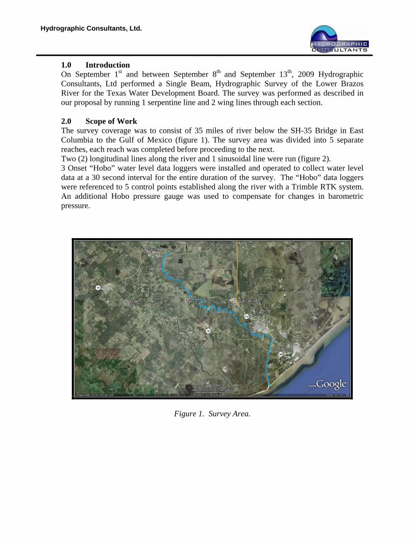
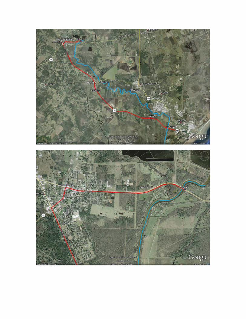
1.0 Introduction On September 1st and between September 8th and September 13th, 2009 Hydrographic Consultants, Ltd performed a Single Beam, Hydrographic Survey of the Lower Brazos River for the Texas Water Development Board. The survey was performed as described in our proposal by running 1 serpentine line and 2 wing lines through each section. 2.0 Scope of Work The survey coverage was to consist of 35 miles of river below the SH-35 Bridge in East Columbia to the Gulf of Mexico (figure 1). The survey area was divided into 5 separate reaches, each reach was completed before proceeding to the next. Two (2) longitudinal lines along the river and 1 sinusoidal line were run (figure 2). 3 Onset “Hobo” water level data loggers were installed and operated to collect water level data at a 30 second interval for the entire duration of the survey. The “Hobo” data loggers were referenced to 5 control points established along the river with a Trimble RTK system. An additional Hobo pressure gauge was used to compensate for changes in barometric pressure.
Figure 1. Survey Area.
Hydrographic Consultants, Ltd.
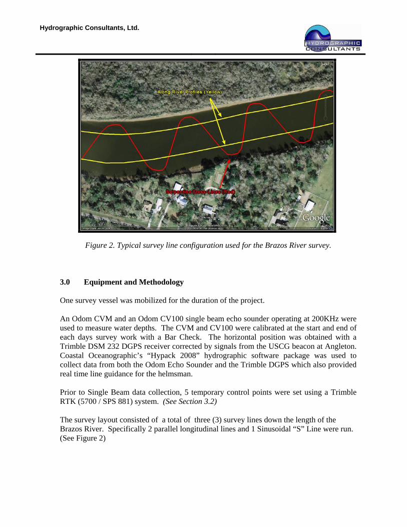
Figure 2. Typical survey line configuration used for the Brazos River survey. 3.0 Equipment and Methodology One survey vessel was mobilized for the duration of the project. An Odom CVM and an Odom CV100 single beam echo sounder operating at 200KHz were used to measure water depths. The CVM and CV100 were calibrated at the start and end of each days survey work with a Bar Check. The horizontal position was obtained with a Trimble DSM 232 DGPS receiver corrected by signals from the USCG beacon at Angleton. Coastal Oceanographic’s “Hypack 2008” hydrographic software package was used to collect data from both the Odom Echo Sounder and the Trimble DGPS which also provided real time line guidance for the helmsman. Prior to Single Beam data collection, 5 temporary control points were set using a Trimble RTK (5700 / SPS 881) system. (See Section 3.2) The survey layout consisted of a total of three (3) survey lines down the length of the Brazos River. Specifically 2 parallel longitudinal lines and 1 Sinusoidal “S” Line were run. (See Figure 2)
Hydrographic Consultants, Ltd.
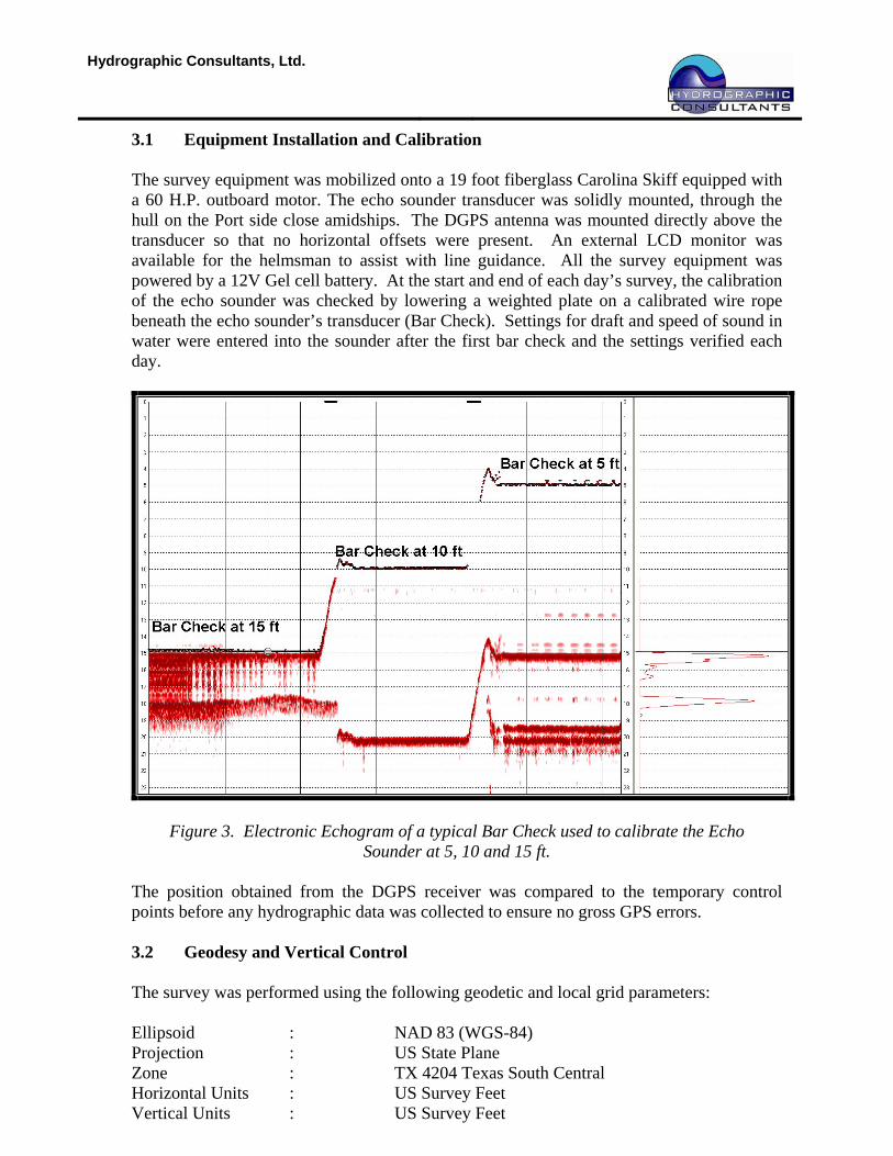
3.1 Equipment Installation and Calibration The survey equipment was mobilized onto a 19 foot fiberglass Carolina Skiff equipped with a 60 H.P. outboard motor. The echo sounder transducer was solidly mounted, through the hull on the Port side close amidships. The DGPS antenna was mounted directly above the transducer so that no horizontal offsets were present. An external LCD monitor was available for the helmsman to assist with line guidance. All the survey equipment was powered by a 12V Gel cell battery. At the start and end of each day’s survey, the calibration of the echo sounder was checked by lowering a weighted plate on a calibrated wire rope beneath the echo sounder’s transducer (Bar Check). Settings for draft and speed of sound in water were entered into the sounder after the first bar check and the settings verified each day.
Figure 3. Electronic Echogram of a typical Bar Check used to calibrate the Echo Sounder at 5, 10 and 15 ft.
The position obtained from the DGPS receiver was compared to the temporary control points before any hydrographic data was collected to ensure no gross GPS errors. 3.2 Geodesy and Vertical Control The survey was performed using the following geodetic and local grid parameters: Ellipsoid : NAD 83 (WGS-84) Projection : US State Plane Zone : TX 4204 Texas South Central Horizontal Units : US Survey Feet Vertical Units : US Survey Feet
Hydrographic Consultants, Ltd.
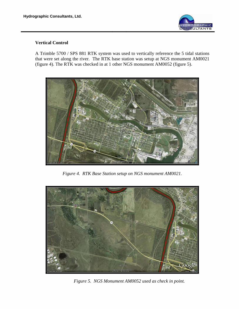
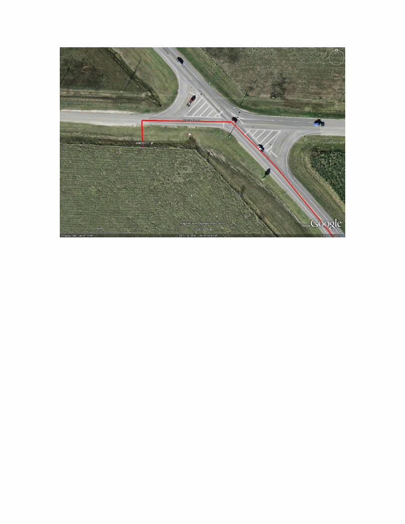
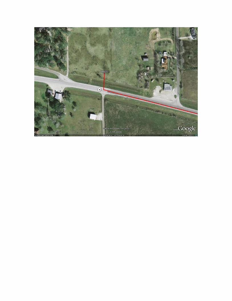
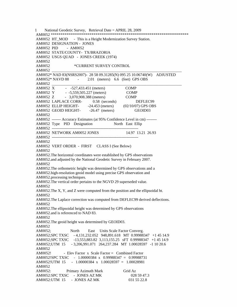
Vertical Control A Trimble 5700 / SPS 881 RTK system was used to vertically reference the 5 tidal stations that were set along the river. The RTK base station was setup at NGS monument AM0021 (figure 4). The RTK was checked in at 1 other NGS monument AM0052 (figure 5).
Figure 4. RTK Base Station setup on NGS monument AM0021.
Figure 5. NGS Monument AM0052 used as check in point.
Hydrographic Consultants, Ltd.
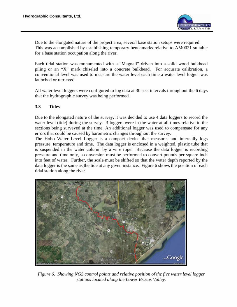
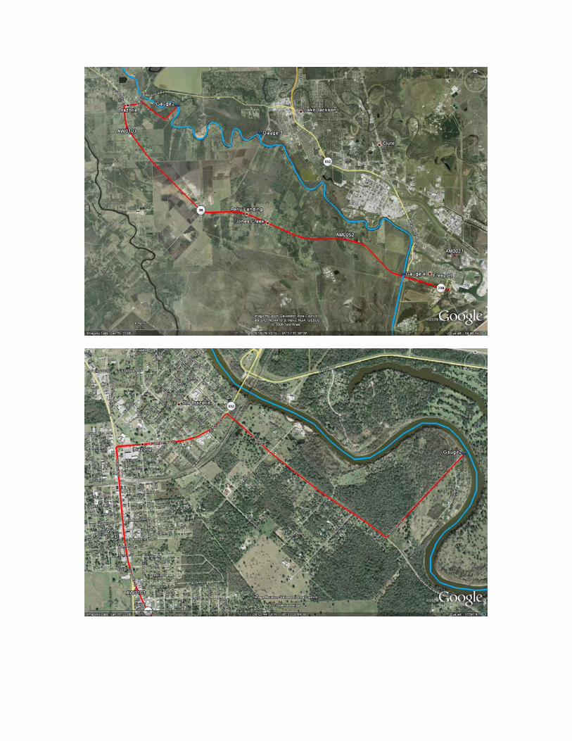
Due to the elongated nature of the project area, several base station setups were required. This was accomplished by establishing temporary benchmarks relative to AM0021 suitable for a base station occupation along the river. Each tidal station was monumented with a “Magnail” driven into a solid wood bulkhead piling or an “X” mark chiseled into a concrete bulkhead. For accurate calibration, a conventional level was used to measure the water level each time a water level logger was launched or retrieved. All water level loggers were configured to log data at 30 sec. intervals throughout the 6 days that the hydrographic survey was being performed. 3.3 Tides Due to the elongated nature of the survey, it was decided to use 4 data loggers to record the water level (tide) during the survey. 3 loggers were in the water at all times relative to the sections being surveyed at the time. An additional logger was used to compensate for any errors that could be caused by barometric changes throughout the survey. The Hobo Water Level Logger is a compact device that measures and internally logs pressure, temperature and time. The data logger is enclosed in a weighted, plastic tube that is suspended in the water column by a wire rope. Because the data logger is recording pressure and time only, a conversion must be performed to convert pounds per square inch into feet of water. Further, the scale must be shifted so that the water depth reported by the data logger is the same as the tide at any given instance. Figure 6 shows the position of each tidal station along the river.
Figure 6. Showing NGS control points and relative position of the five water level logger stations located along the Lower Brazos Valley.
Hydrographic Consultants, Ltd.
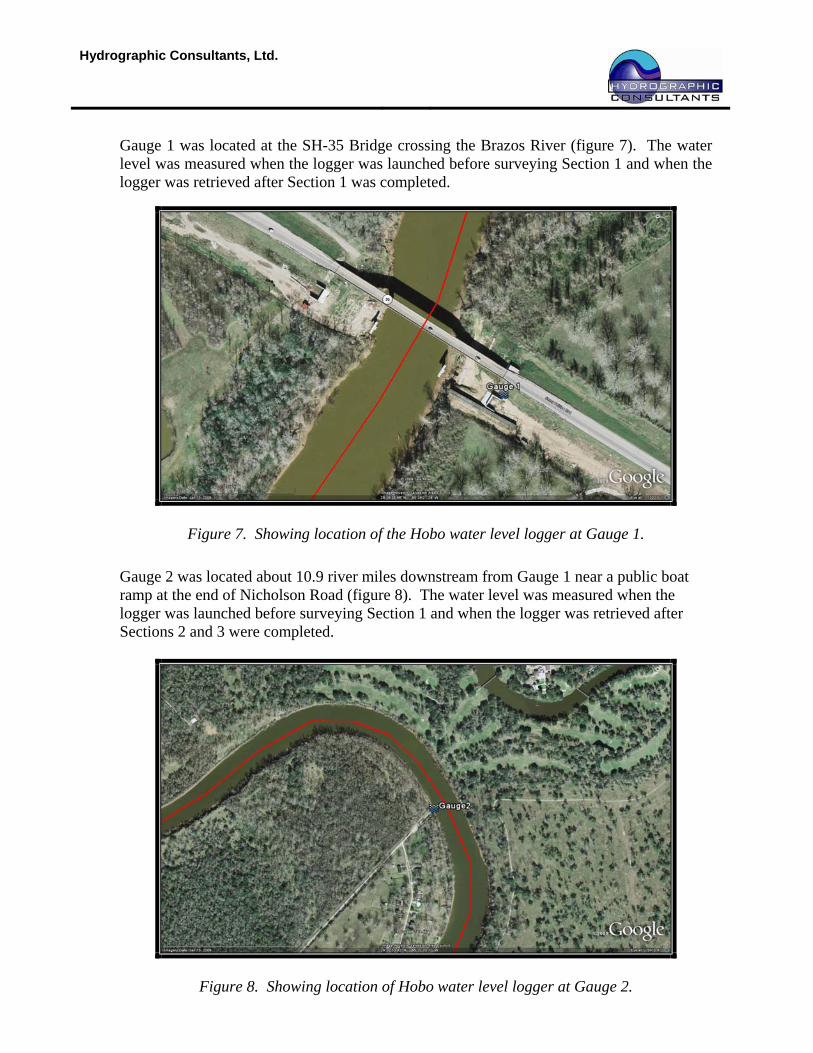
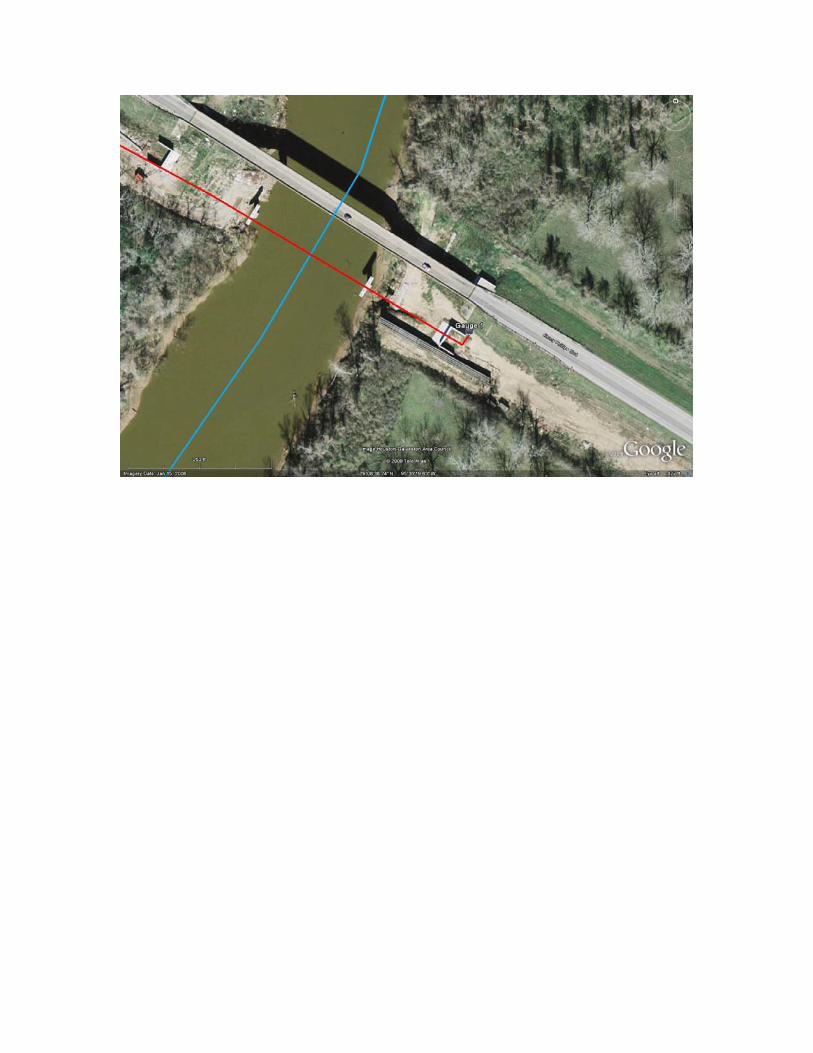
Gauge 1 was located at the SH-35 Bridge crossing the Brazos River (figure 7). The water level was measured when the logger was launched before surveying Section 1 and when the logger was retrieved after Section 1 was completed.
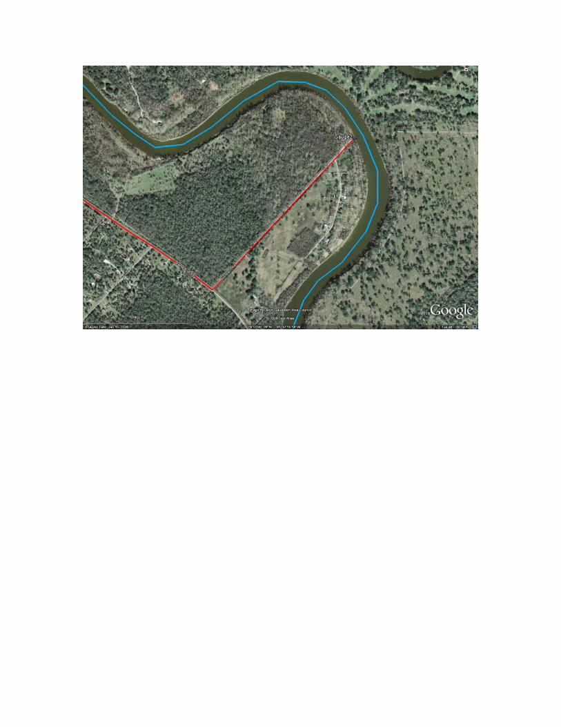
Figure 7. Showing location of the Hobo water level logger at Gauge 1. Gauge 2 was located about 10.9 river miles downstream from Gauge 1 near a public boat ramp at the end of Nicholson Road (figure 8). The water level was measured when the logger was launched before surveying Section 1 and when the logger was retrieved after Sections 2 and 3 were completed.
Figure 8. Showing location of Hobo water level logger at Gauge 2.
Hydrographic Consultants, Ltd.
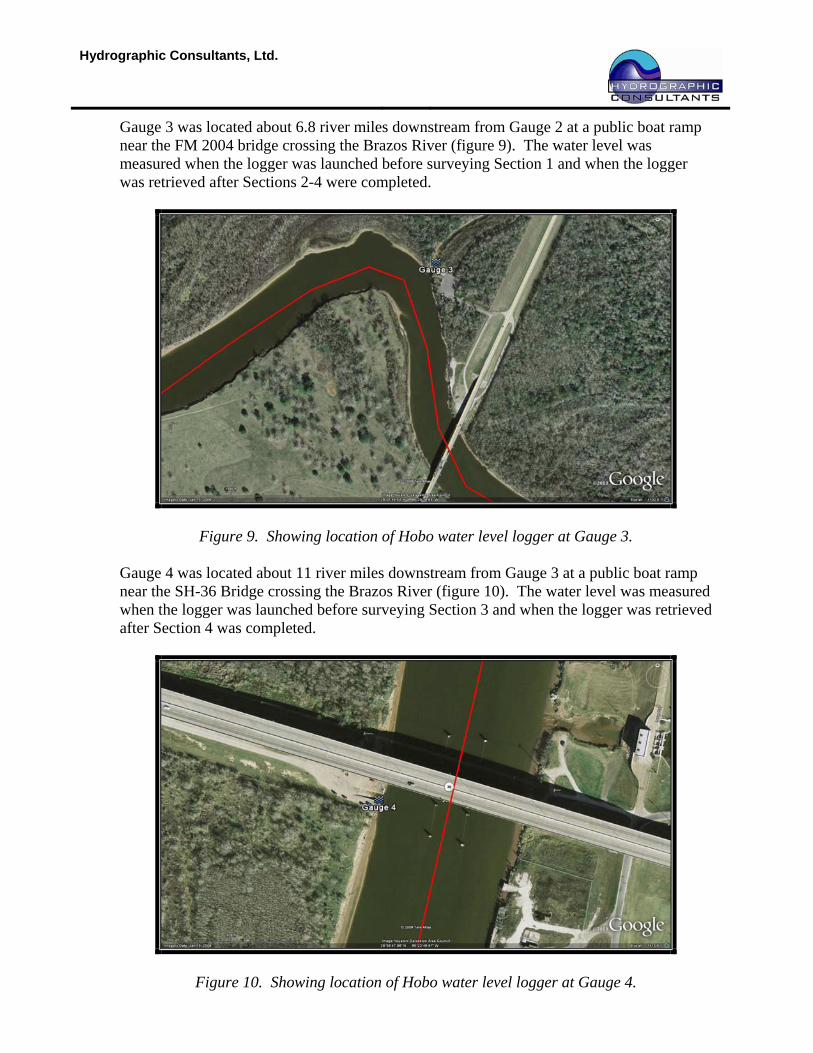
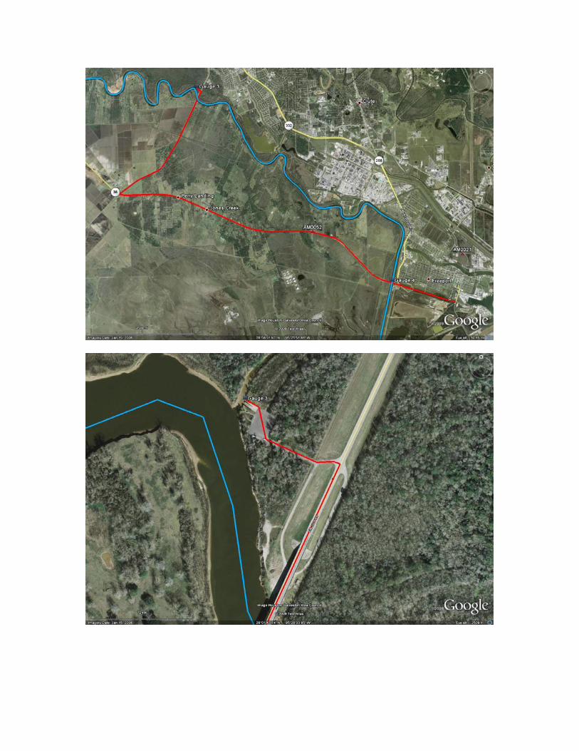
Gauge 3 was located about 6.8 river miles downstream from Gauge 2 at a public boat ramp near the FM 2004 bridge crossing the Brazos River (figure 9). The water level was measured when the logger was launched before surveying Section 1 and when the logger was retrieved after Sections 2-4 were completed.
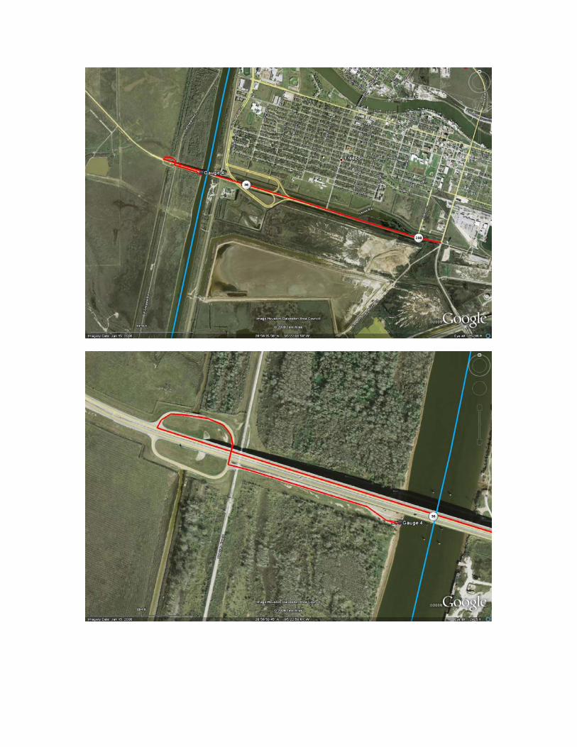
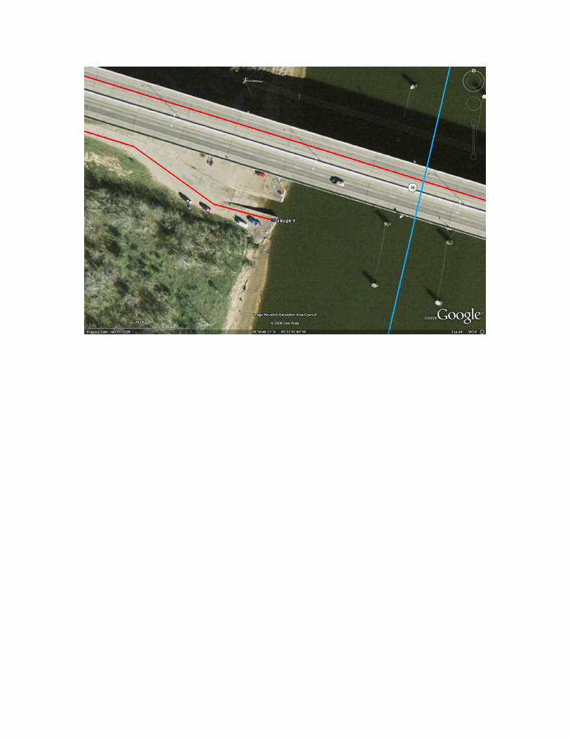
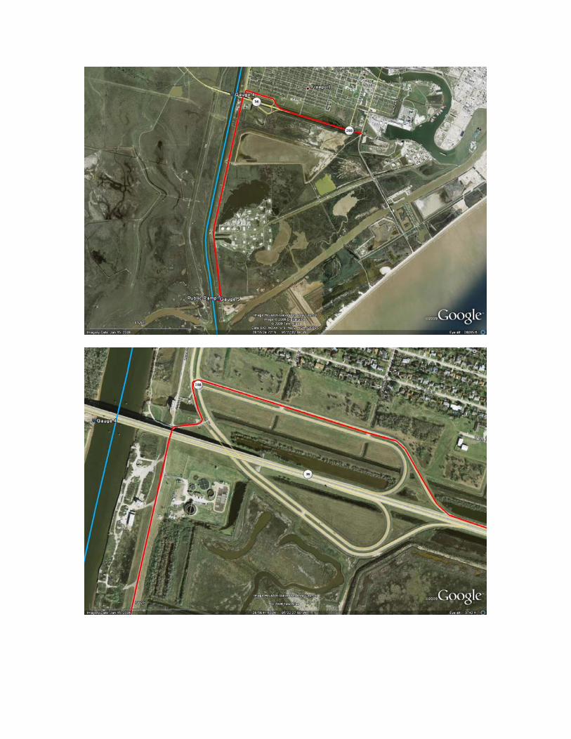
Figure 9. Showing location of Hobo water level logger at Gauge 3. Gauge 4 was located about 11 river miles downstream from Gauge 3 at a public boat ramp near the SH-36 Bridge crossing the Brazos River (figure 10). The water level was measured when the logger was launched before surveying Section 3 and when the logger was retrieved after Section 4 was completed.
Figure 10. Showing location of Hobo water level logger at Gauge 4.
Hydrographic Consultants, Ltd.
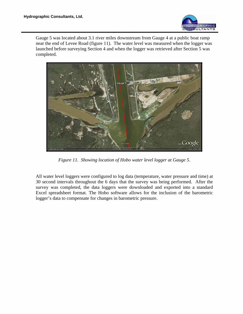
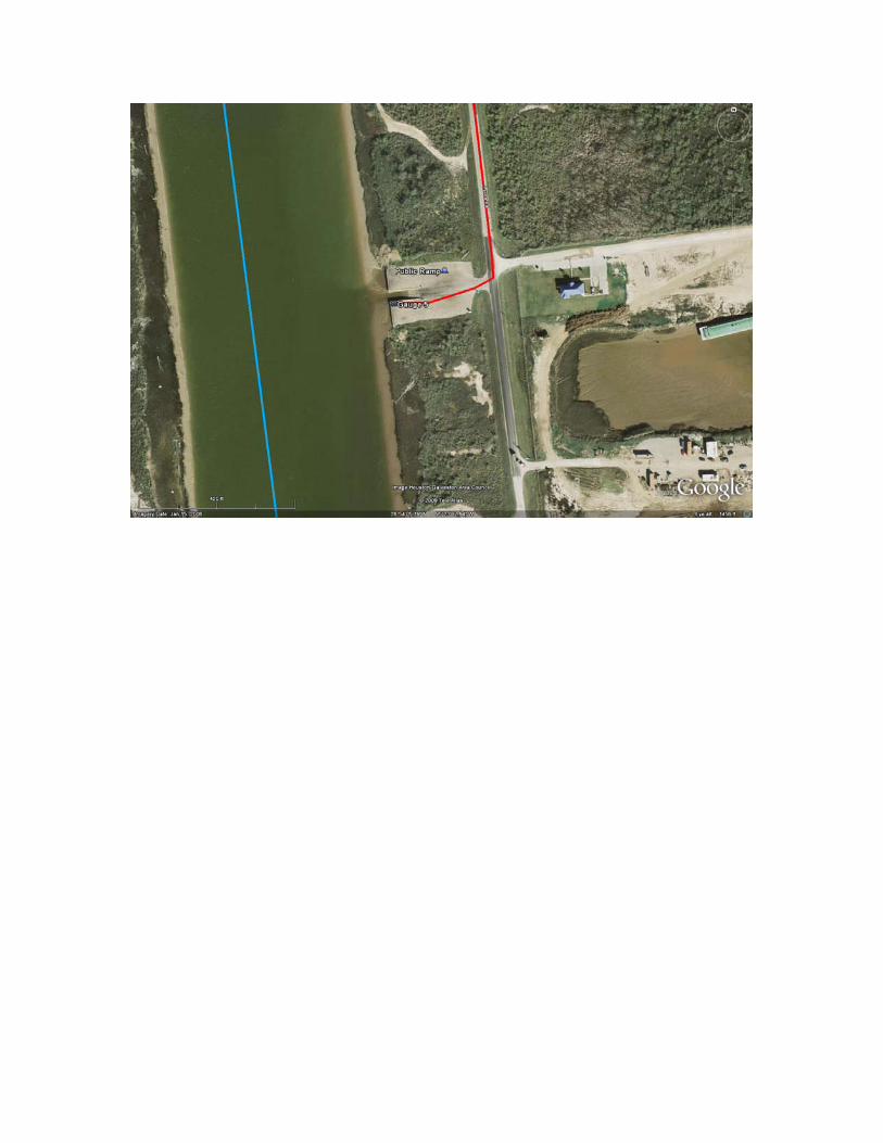
Gauge 5 was located about 3.1 river miles downstream from Gauge 4 at a public boat ramp near the end of Levee Road (figure 11). The water level was measured when the logger was launched before surveying Section 4 and when the logger was retrieved after Section 5 was completed.
Figure 11. Showing location of Hobo water level logger at Gauge 5.
All water level loggers were configured to log data (temperature, water pressure and time) at 30 second intervals throughout the 6 days that the survey was being performed. After the survey was completed, the data loggers were downloaded and exported into a standard Excel spreadsheet format. The Hobo software allows for the inclusion of the barometric logger’s data to compensate for changes in barometric pressure.
Hydrographic Consultants, Ltd.
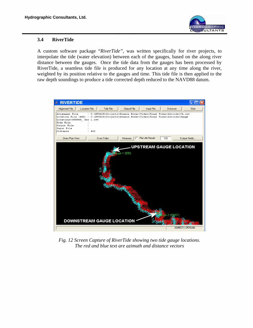
3.4 RiverTide A custom software package “RiverTide”, was written specifically for river projects, to interpolate the tide (water elevation) between each of the gauges, based on the along river distance between the gauges. Once the tide data from the gauges has been processed by RiverTide, a seamless tide file is produced for any location at any time along the river, weighted by its position relative to the gauges and time. This tide file is then applied to the raw depth soundings to produce a tide corrected depth reduced to the NAVD88 datum.
Fig. 12 Screen Capture of RiverTide showing two tide gauge locations. The red and blue text are azimuth and distance vectors
Hydrographic Consultants, Ltd.
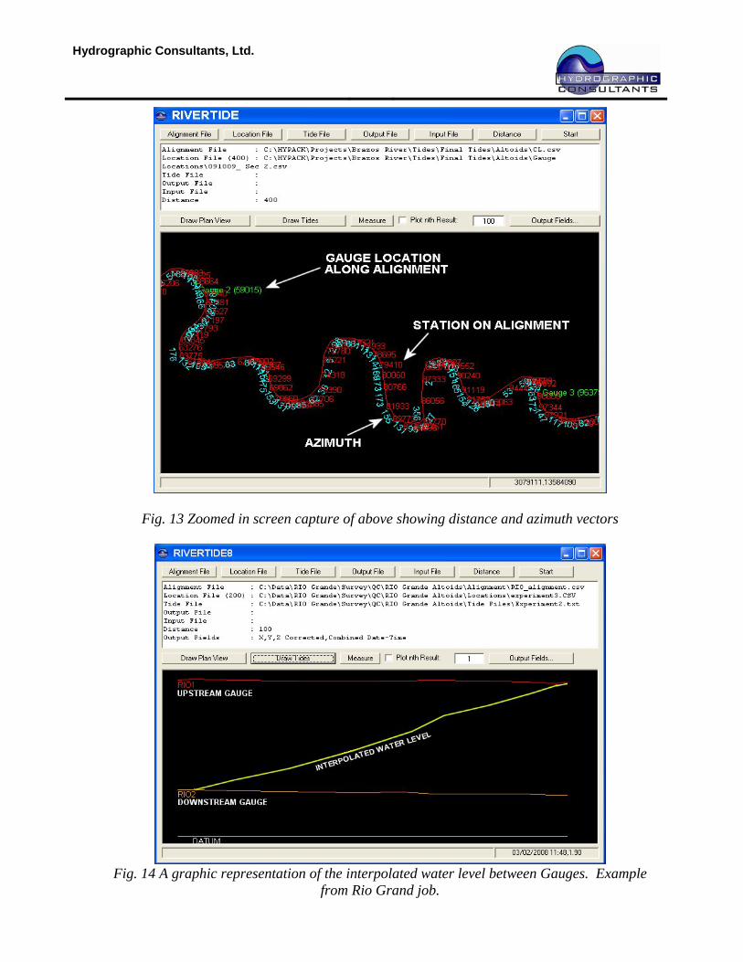
Fig. 13 Zoomed in screen capture of above showing distance and azimuth vectors
Fig. 14 A graphic representation of the interpolated water level between Gauges. Example
from Rio Grand job.
Hydrographic Consultants, Ltd.
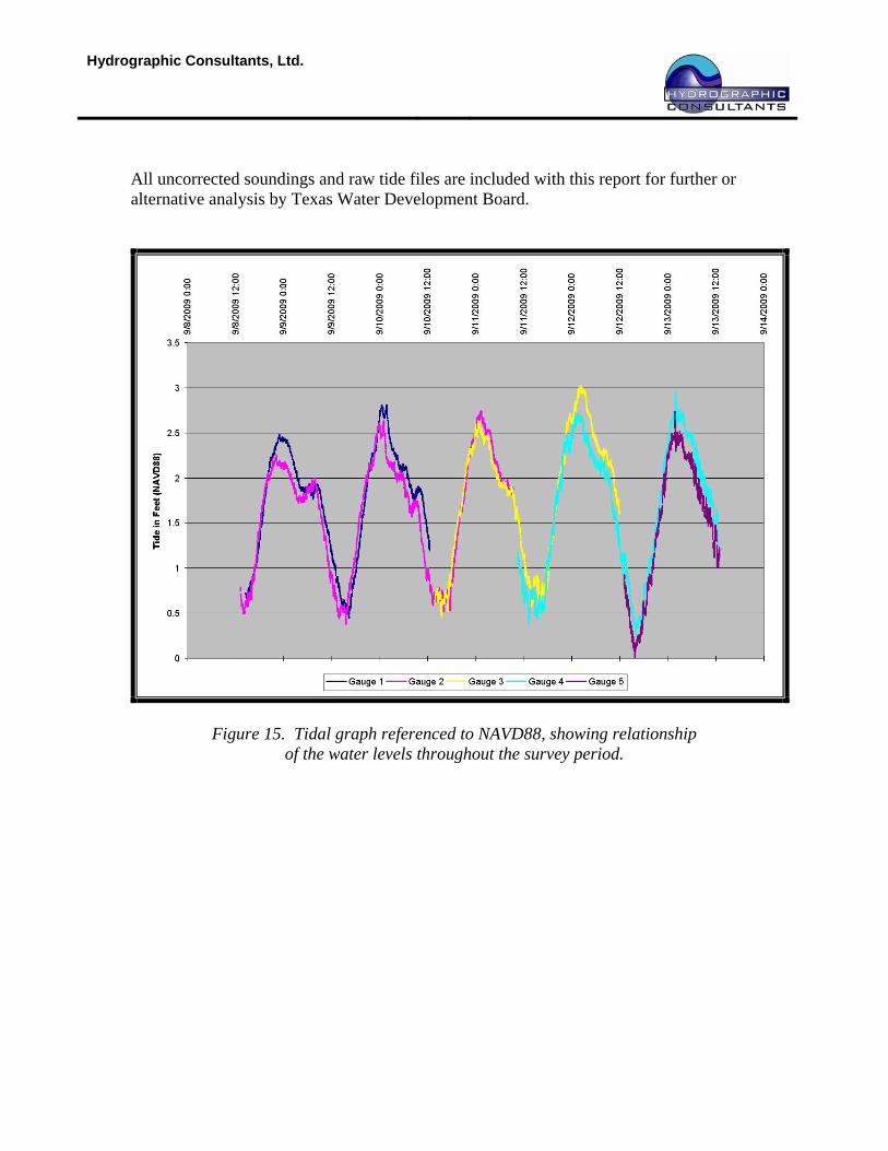
All uncorrected soundings and raw tide files are included with this report for further or alternative analysis by Texas Water Development Board.
Figure 15. Tidal graph referenced to NAVD88, showing relationship of the water levels throughout the survey period.
Hydrographic Consultants, Ltd.
Survey Results 4.1 Data Cleaning and Processing
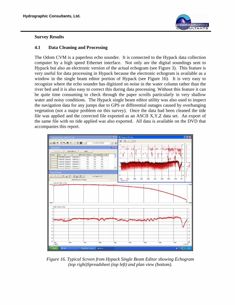
The Odom CVM is a paperless echo sounder. It is connected to the Hypack data collection computer by a high speed Ethernet interface. Not only are the digital soundings sent to Hypack but also an electronic version of the actual echogram (see Figure 3). This feature is very useful for data processing in Hypack because the electronic echogram is available as a window in the single beam editor portion of Hypack (see Figure 16). It is very easy to recognize where the echo sounder has digitized on noise in the water column rather than the river bed and it is also easy to correct this during data processing. Without this feature it can be quite time consuming to check through the paper scrolls particularly in very shallow water and noisy conditions. The Hypack single beam editor utility was also used to inspect the navigation data for any jumps due to GPS or differential outages caused by overhanging vegetation (not a major problem on this survey). Once the data had been cleaned the tide file was applied and the corrected file exported as an ASCII X,Y,Z data set. An export of the same file with no tide applied was also exported. All data is available on the DVD that accompanies this report.
Figure 16. Typical Screen from Hypack Single Beam Editor showing Echogram (top right)Spreadsheet (top left) and plan view (bottom).
Hydrographic Consultants, Ltd.
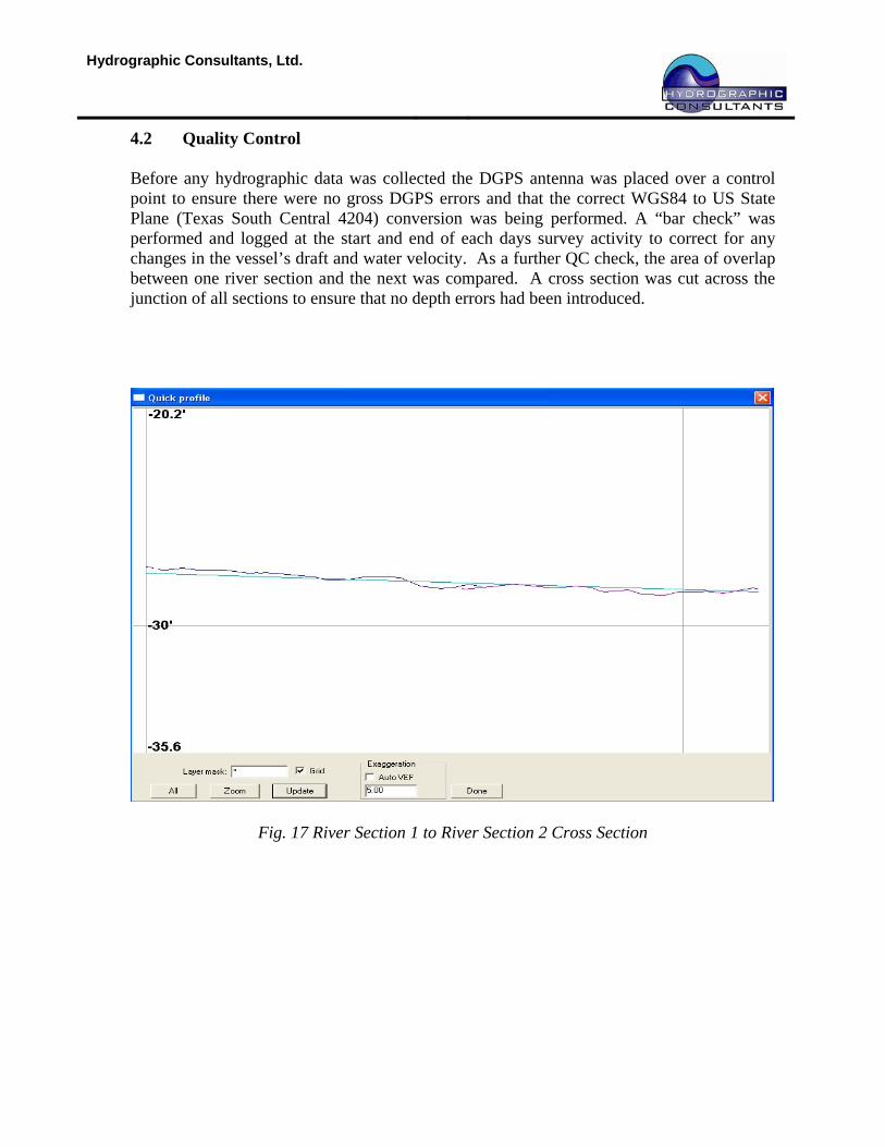
4.2 Quality Control Before any hydrographic data was collected the DGPS antenna was placed over a control point to ensure there were no gross DGPS errors and that the correct WGS84 to US State Plane (Texas South Central 4204) conversion was being performed. A “bar check” was performed and logged at the start and end of each days survey activity to correct for any changes in the vessel’s draft and water velocity. As a further QC check, the area of overlap between one river section and the next was compared. A cross section was cut across the junction of all sections to ensure that no depth errors had been introduced.
Fig. 17 River Section 1 to River Section 2 Cross Section
Hydrographic Consultants, Ltd.
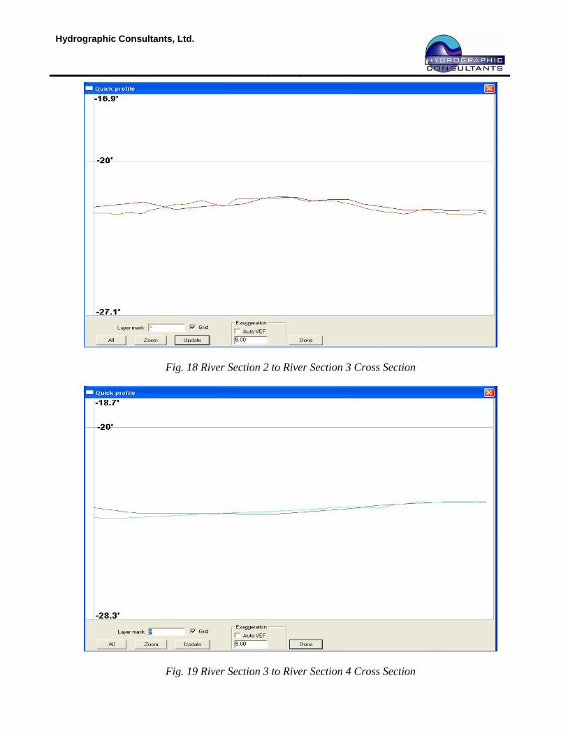
Fig. 18 River Section 2 to River Section 3 Cross Section
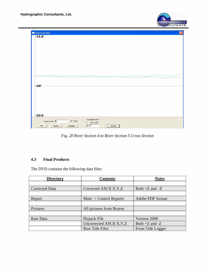
Fig. 19 River Section 3 to River Section 4 Cross Section
Hydrographic Consultants, Ltd.
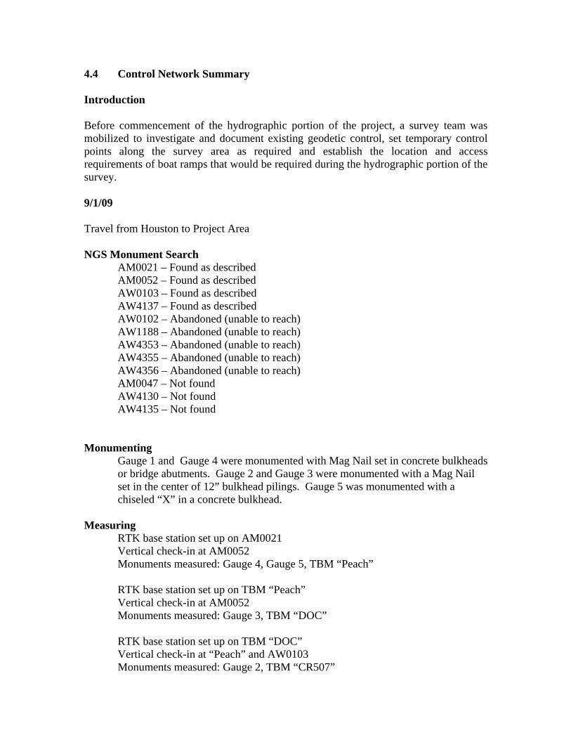
Fig. 20 River Section 4 to River Section 5 Cross Section 4.3 Final Products The DVD contains the following data files:
Directory Contents Notes Corrected Data Corrected ASCII X,Y,Z Both +Z and –Z Report Main + Control Reports Adobe PDF format Pictures All pictures from Brazos Raw Data Hypack File Version 2008 Uncorrected ASCII X,Y,Z Both +Z and -Z Raw Tide Files From Tide Logger
4.4 Control Network Summary Introduction Before commencement of the hydrographic portion of the project, a survey team was mobilized to investigate and document existing geodetic control, set temporary control points along the survey area as required and establish the location and access requirements of boat ramps that would be required during the hydrographic portion of the survey. 9/1/09 Travel from Houston to Project Area NGS Monument Search
AM0021 – Found as described AM0052 – Found as described AW0103 – Found as described AW4137 – Found as described AW0102 – Abandoned (unable to reach) AW1188 – Abandoned (unable to reach) AW4353 – Abandoned (unable to reach) AW4355 – Abandoned (unable to reach) AW4356 – Abandoned (unable to reach) AM0047 – Not found AW4130 – Not found AW4135 – Not found
Monumenting Gauge 1 and Gauge 4 were monumented with Mag Nail set in concrete bulkheads or bridge abutments. Gauge 2 and Gauge 3 were monumented with a Mag Nail set in the center of 12” bulkhead pilings. Gauge 5 was monumented with a chiseled “X” in a concrete bulkhead.
Measuring
RTK base station set up on AM0021 Vertical check-in at AM0052 Monuments measured: Gauge 4, Gauge 5, TBM “Peach” RTK base station set up on TBM “Peach” Vertical check-in at AM0052 Monuments measured: Gauge 3, TBM “DOC” RTK base station set up on TBM “DOC” Vertical check-in at “Peach” and AW0103 Monuments measured: Gauge 2, TBM “CR507”

RTK base station set up on TBM “CR507” Vertical check-in at AW0103, AW4137 Monuments measured: TBM “4137” RTK base station set up on TBM “4137” Vertical check-in at “CR507” Monuments measured: Gauge 1
Travel from Project Area to Houston

HCL Vertical Control Descriptions and Locations
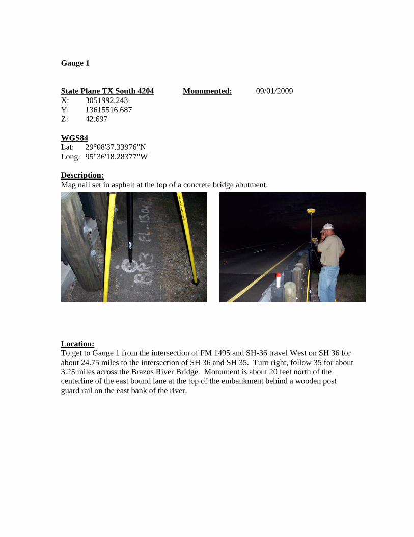
Gauge 1 State Plane TX South 4204 Monumented: 09/01/2009 X: 3051992.243 Y: 13615516.687 Z: 42.697 WGS84 Lat: 29°08'37.33976"N Long: 95°36'18.28377"W Description: Mag nail set in asphalt at the top of a concrete bridge abutment. Location: To get to Gauge 1 from the intersection of FM 1495 and SH-36 travel West on SH 36 for about 24.75 miles to the intersection of SH 36 and SH 35. Turn right, follow 35 for about 3.25 miles across the Brazos River Bridge. Monument is about 20 feet north of the centerline of the east bound lane at the top of the embankment behind a wooden post guard rail on the east bank of the river.
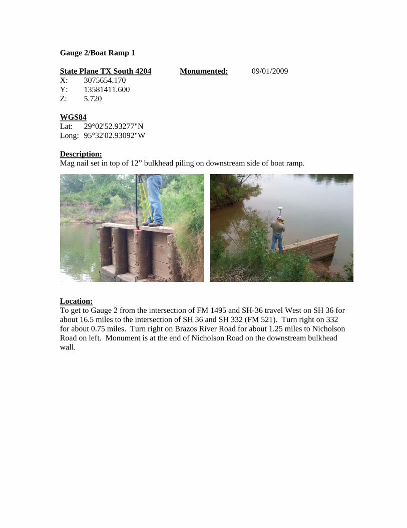
Gauge 2/Boat Ramp 1 State Plane TX South 4204 Monumented: 09/01/2009 X: 3075654.170 Y: 13581411.600 Z: 5.720 WGS84 Lat: 29°02'52.93277"N Long: 95°32'02.93092"W Description: Mag nail set in top of 12” bulkhead piling on downstream side of boat ramp. Location: To get to Gauge 2 from the intersection of FM 1495 and SH-36 travel West on SH 36 for about 16.5 miles to the intersection of SH 36 and SH 332 (FM 521). Turn right on 332 for about 0.75 miles. Turn right on Brazos River Road for about 1.25 miles to Nicholson Road on left. Monument is at the end of Nicholson Road on the downstream bulkhead wall.
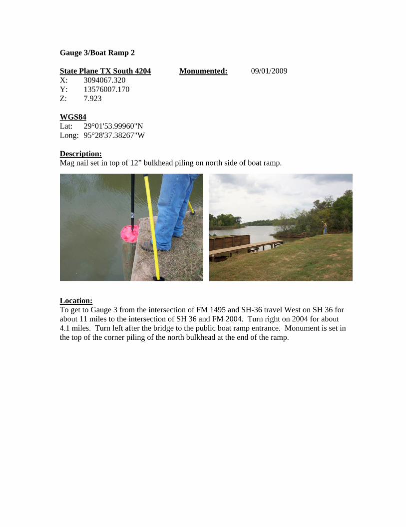
Gauge 3/Boat Ramp 2 State Plane TX South 4204 Monumented: 09/01/2009 X: 3094067.320 Y: 13576007.170 Z: 7.923 WGS84 Lat: 29°01'53.99960"N Long: 95°28'37.38267"W Description: Mag nail set in top of 12” bulkhead piling on north side of boat ramp. Location: To get to Gauge 3 from the intersection of FM 1495 and SH-36 travel West on SH 36 for about 11 miles to the intersection of SH 36 and FM 2004. Turn right on 2004 for about 4.1 miles. Turn left after the bridge to the public boat ramp entrance. Monument is set in the top of the corner piling of the north bulkhead at the end of the ramp.
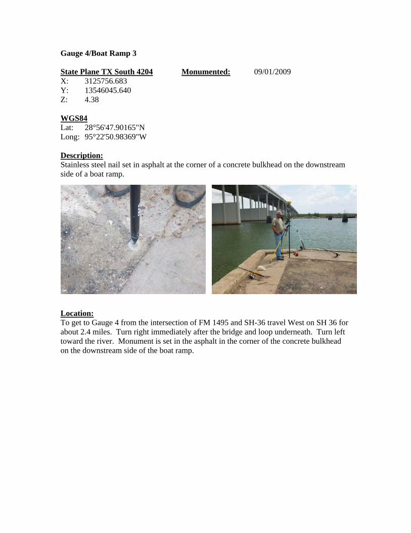
Gauge 4/Boat Ramp 3 State Plane TX South 4204 Monumented: 09/01/2009 X: 3125756.683 Y: 13546045.640 Z: 4.38 WGS84 Lat: 28°56'47.90165"N Long: 95°22'50.98369"W Description: Stainless steel nail set in asphalt at the corner of a concrete bulkhead on the downstream side of a boat ramp. Location: To get to Gauge 4 from the intersection of FM 1495 and SH-36 travel West on SH 36 for about 2.4 miles. Turn right immediately after the bridge and loop underneath. Turn left toward the river. Monument is set in the asphalt in the corner of the concrete bulkhead on the downstream side of the boat ramp.
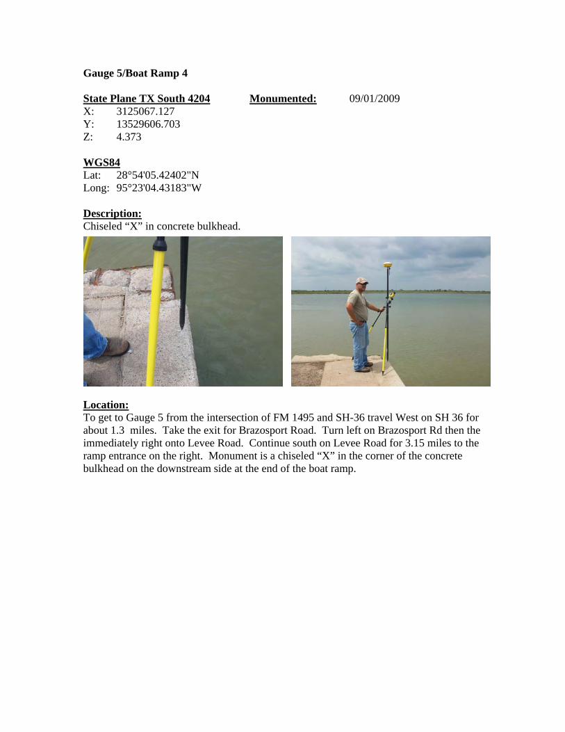
Gauge 5/Boat Ramp 4 State Plane TX South 4204 Monumented: 09/01/2009 X: 3125067.127 Y: 13529606.703 Z: 4.373 WGS84 Lat: 28°54'05.42402"N Long: 95°23'04.43183"W Description: Chiseled “X” in concrete bulkhead. Location: To get to Gauge 5 from the intersection of FM 1495 and SH-36 travel West on SH 36 for about 1.3 miles. Take the exit for Brazosport Road. Turn left on Brazosport Rd then the immediately right onto Levee Road. Continue south on Levee Road for 3.15 miles to the ramp entrance on the right. Monument is a chiseled “X” in the corner of the concrete bulkhead on the downstream side at the end of the boat ramp.
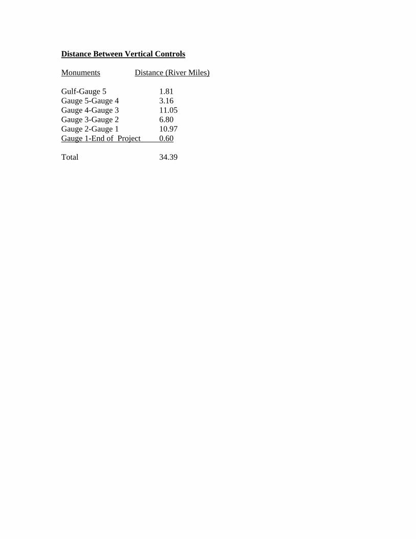
Distance Between Vertical Controls Monuments Distance (River Miles) Gulf-Gauge 5 1.81 Gauge 5-Gauge 4 3.16 Gauge 4-Gauge 3 11.05 Gauge 3-Gauge 2 6.80 Gauge 2-Gauge 1 10.97 Gauge 1-End of Project 0.60 Total 34.39

NGS Control Descriptions and Locations (as found by HCL)
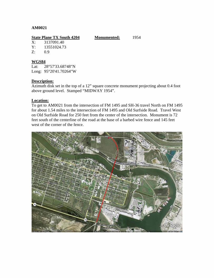
AM0021 State Plane TX South 4204 Monumented: 1954 X: 3137091.40 Y: 13551024.73 Z: 0.9 WGS84 Lat: 28°57'33.68748"N Long: 95°20'41.70264"W Description: Azimuth disk set in the top of a 12” square concrete monument projecting about 0.4 foot above ground level. Stamped “MIDWAY 1954”. Location: To get to AM0021 from the intersection of FM 1495 and SH-36 travel North on FM 1495 for about 1.54 miles to the intersection of FM 1495 and Old Surfside Road. Travel West on Old Surfside Road for 250 feet from the center of the intersection. Monument is 72 feet south of the centerline of the road at the base of a barbed wire fence and 145 feet west of the corner of the fence.
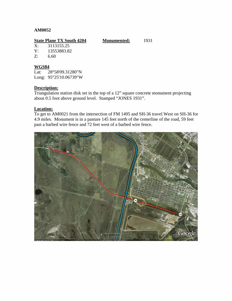
AM0052 State Plane TX South 4204 Monumented: 1931 X: 3113155.25 Y: 13553883.82 Z: 6.60 WGS84 Lat: 28°58'09.31280"N Long: 95°25'10.06739"W Description: Triangulation station disk set in the top of a 12” square concrete monument projecting about 0.5 foot above ground level. Stamped “JONES 1931”. Location: To get to AM0021 from the intersection of FM 1495 and SH-36 travel West on SH-36 for 4.9 miles. Monument is in a pasture 145 feet north of the centerline of the road, 59 feet past a barbed wire fence and 72 feet west of a barbed wire fence.
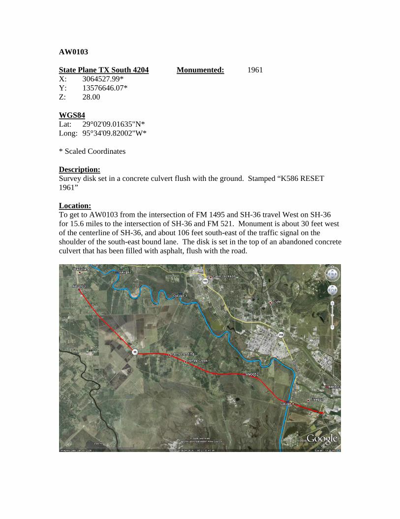
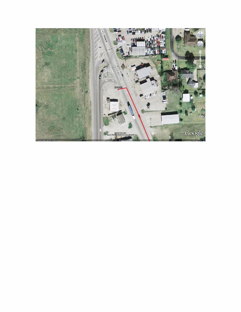
AW0103 State Plane TX South 4204 Monumented: 1961 X: 3064527.99* Y: 13576646.07* Z: 28.00 WGS84 Lat: 29°02'09.01635"N* Long: 95°34'09.82002"W* * Scaled Coordinates Description: Survey disk set in a concrete culvert flush with the ground. Stamped “K586 RESET 1961” Location: To get to AW0103 from the intersection of FM 1495 and SH-36 travel West on SH-36 for 15.6 miles to the intersection of SH-36 and FM 521. Monument is about 30 feet west of the centerline of SH-36, and about 106 feet south-east of the traffic signal on the shoulder of the south-east bound lane. The disk is set in the top of an abandoned concrete culvert that has been filled with asphalt, flush with the road.
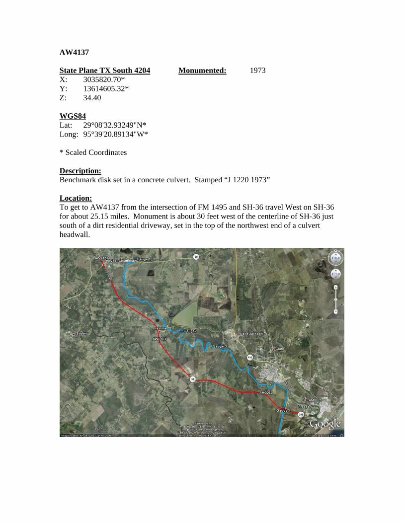
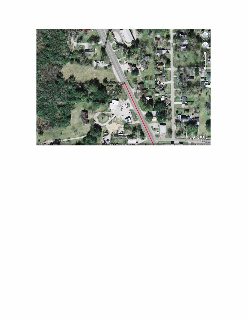
AW4137 State Plane TX South 4204 Monumented: 1973 X: 3035820.70* Y: 13614605.32* Z: 34.40 WGS84 Lat: 29°08'32.93249"N* Long: 95°39'20.89134"W* * Scaled Coordinates Description: Benchmark disk set in a concrete culvert. Stamped “J 1220 1973” Location: To get to AW4137 from the intersection of FM 1495 and SH-36 travel West on SH-36 for about 25.15 miles. Monument is about 30 feet west of the centerline of SH-36 just south of a dirt residential driveway, set in the top of the northwest end of a culvert headwall.

NGS Control Data Sheets
1 National Geodetic Survey, Retrieval Date = APRIL 27, 2009 AM0021 *********************************************************************** AM0021 HT_MOD - This is a Height Modernization Survey Station. AM0021 DESIGNATION - MIDWAY AZ MK AM0021 PID - AM0021 AM0021 STATE/COUNTY- TX/BRAZORIA AM0021 USGS QUAD - FREEPORT (1974) AM0021 AM0021 *CURRENT SURVEY CONTROL AM0021 ___________________________________________________________________ AM0021* NAD 83(NSRS2007)- 28 57 33.68748(N) 095 20 41.70263(W) ADJUSTED AM0021* NAVD 88 - 0.26 (meters) 0.9 (feet) GPS OBS AM0021 ___________________________________________________________________ AM0021 X - -520,249.045 (meters) COMP AM0021 Y - -5,560,714.109 (meters) COMP AM0021 Z - 3,069,947.940 (meters) COMP AM0021 LAPLACE CORR- 0.69 (seconds) DEFLEC99 AM0021 ELLIP HEIGHT- -26.150 (meters) (02/10/07) GPS OBS AM0021 GEOID HEIGHT- -26.41 (meters) GEOID03 AM0021 AM0021 ------- Accuracy Estimates (at 95% Confidence Level in cm) -------- AM0021 Type PID Designation North East Ellip AM0021 ------------------------------------------------------------------- AM0021 NETWORK AM0021 MIDWAY AZ MK 11.15 10.33 25.77 AM0021 ------------------------------------------------------------------- AM0021 LOCAL AW0096 PLANT B 2 13.19 11.78 15.17 AM0021 LOCAL AM0024 PLANT A 11.70 9.96 10.35 AM0021 LOCAL AM0052 JONES 14.11 12.31 13.82 AM0021 ------------------------------------------------------------------- AM0021 LOCAL AVERAGE 13.00 11.35 13.11 AM0021 AM0021 VERT ORDER - FIRST CLASS I (See Below) AM0021 AM0021.The horizontal coordinates were established by GPS observations AM0021.and adjusted by the National Geodetic Survey in February 2007. AM0021 AM0021.The orthometric height was determined by GPS observations and a AM0021.high-resolution geoid model using precise GPS observation and AM0021.processing techniques. AM0021.The vertical order pertains to the NGVD 29 superseded value. AM0021 AM0021.The X, Y, and Z were computed from the position and the ellipsoidal ht. AM0021 AM0021.The Laplace correction was computed from DEFLEC99 derived deflections. AM0021 AM0021.The ellipsoidal height was determined by GPS observations AM0021.and is referenced to NAD 83. AM0021 AM0021.The geoid height was determined by GEOID03. AM0021 AM0021; North East Units Scale Factor Converg. AM0021;SPC TXSC - 4,130,360.598 956,187.371 MT 0.99988458 +1 47 26.4 AM0021;SPC TXSC -13,551,024.73 3,137,091.40 sFT 0.99988458 +1 47 26.4 AM0021;UTM 15 - 3,205,747.792 271,481.790 MT 1.00024446 -1 08 09.2 AM0021 AM0021! - Elev Factor x Scale Factor = Combined Factor AM0021!SPC TXSC - 1.00000411 x 0.99988458 = 0.99988869
AM0021!UTM 15 - 1.00000411 x 1.00024446 = 1.00024857 AM0021 AM0021 SUPERSEDED SURVEY CONTROL AM0021 AM0021 NAD 83(1993)- 28 57 33.68720(N) 095 20 41.70275(W) AD( ) 1 AM0021 ELLIP H (12/03/01) -26.082 (m) GP( ) 4 2 AM0021 NAD 83(1993)- 28 57 33.68543(N) 095 20 41.69838(W) AD( ) 3 AM0021 NAD 83(1986)- 28 57 33.69479(N) 095 20 41.67773(W) AD( ) 3 AM0021 NAD 27 - 28 57 32.80500(N) 095 20 40.89500(W) AD( ) 3 AM0021 NGVD 29 (??/??/92) 0.380 (m) 1.25 (f) ADJ UNCH 1 1 AM0021 AM0021.Superseded values are not recommended for survey control. AM0021.NGS no longer adjusts projects to the NAD 27 or NGVD 29 datums. AM0021.See file dsdata.txt to determine how the superseded data were derived. AM0021 AM0021_U.S. NATIONAL GRID SPATIAL ADDRESS: 15RTN7148205748(NAD83) AM0021_MARKER: DZ = AZIMUTH MARK DISK AM0021_SETTING: 7 = SET IN TOP OF CONCRETE MONUMENT AM0021_SP_SET: SET IN TOP OF CONCRETE MONUMENT AM0021_STAMPING: MIDWAY 1954 AM0021_STABILITY: C = MAY HOLD, BUT OF TYPE COMMONLY SUBJECT TO AM0021+STABILITY: SURFACE MOTION AM0021_SATELLITE: THE SITE LOCATION WAS REPORTED AS SUITABLE FOR AM0021+SATELLITE: SATELLITE OBSERVATIONS - February 18, 2005 AM0021 AM0021 HISTORY - Date Condition Report By AM0021 HISTORY - 1954 MONUMENTED CGS AM0021 HISTORY - 1973 GOOD NGS AM0021 HISTORY - 1978 GOOD NGS AM0021 HISTORY - 20050218 GOOD USPSQD AM0021 AM0021 STATION DESCRIPTION AM0021 AM0021'DESCRIBED BY COAST AND GEODETIC SURVEY 1954 AM0021'REACHED FROM THE JUNCTION OF STATE HIGHWAY 523 AND FARM AND AM0021'MARKET ROAD 1460 IN THE EASTERN EDGE OF VELASCO BY GOING AM0021'EASTERLY ON ROAD 1460 FOR 0.3 MILE TO STATION MIDWAY ON THE LEFT. AM0021'TO REACH THE AZIMUTH MARK FROM STATION MIDWAY, CONTINUE EASTERLY AM0021'ON ROAD 1460 FOR 0.3 MILE TO THE AZIMUTH MARK ON THE RIGHT. AM0021' AM0021'THE AZIMUTH MARK, A STANDARD DISK SET IN A CONCRETE MONUMENT, AM0021'IS 73 FEET SOUTH OF THE CENTERLINE OF ROAD 1460, 6 FEET NORTH AM0021'OF A CABLE LINE POLE, 3 FEET WEST OF A WITNESS POST, AND 1 AM0021'FOOT WEST OF A FENCE LINE. THE DISK IS STAMPED MIDWAY 1954, AM0021'AND THE MARK PROJECTS 4 INCHES. AM0021 AM0021 STATION RECOVERY (1973) AM0021 AM0021'RECOVERY NOTE BY NATIONAL GEODETIC SURVEY 1973 AM0021'0.65 MI E FROM FREEPORT. AM0021'0.65 MILE EAST ALONG COUNTY ROAD 229 FROM THE JUNCTION OF VELASCO AM0021'BOULEVARD AT FREEPORT, AT THE JUNCTION OF FARM ROAD 1495 (PINE AM0021'STREET), 71 FEET SOUTH OF THE CENTER LINE OF THE COUNTY ROAD, 296 FEET AM0021'WEST-SOUTHWEST OF THE CENTER OF THE JUNCTION, 61 FEET EAST OF A AM0021'TELEPHONE POLE, 81 1/2 FEET WEST OF TELEPHONE POLE 11 1/2 WITH A GUY AM0021'WIRE, 77 FEET WEST OF A METAL BOX OF AN UNDERGROUND TELEPHONECABLE, AM0021'1.0 FOOT NORTH OF A FENCE, 2.0 FEET EAST OF A WITNESS POST, ABOUT 1/2

AM0021'FOOT LOWER THAN THE ROAD, AND SET IN THE TOP OF A CONCRETE POST AM0021'PROJECTING 0.4 FOOT ABOVE THE GROUND. AM0021 AM0021 STATION RECOVERY (1978) AM0021 AM0021'RECOVERY NOTE BY NATIONAL GEODETIC SURVEY 1978 AM0021'RECOVERED IN GOOD CONDITION. AM0021 AM0021 STATION RECOVERY (2005) AM0021 AM0021'RECOVERY NOTE BY US POWER SQUADRON 2005 (GWS) AM0021'RECOVERED IN GOOD CONDITION.
1 National Geodetic Survey, Retrieval Date = APRIL 28, 2009 AM0052 *********************************************************************** AM0052 HT_MOD - This is a Height Modernization Survey Station. AM0052 DESIGNATION - JONES AM0052 PID - AM0052 AM0052 STATE/COUNTY- TX/BRAZORIA AM0052 USGS QUAD - JONES CREEK (1974) AM0052 AM0052 *CURRENT SURVEY CONTROL AM0052 ___________________________________________________________________ AM0052* NAD 83(NSRS2007)- 28 58 09.31285(N) 095 25 10.06740(W) ADJUSTED AM0052* NAVD 88 - 2.01 (meters) 6.6 (feet) GPS OBS AM0052 ___________________________________________________________________ AM0052 X - -527,433.451 (meters) COMP AM0052 Y - -5,559,505.227 (meters) COMP AM0052 Z - 3,070,908.388 (meters) COMP AM0052 LAPLACE CORR- 0.58 (seconds) DEFLEC99 AM0052 ELLIP HEIGHT- -24.453 (meters) (02/10/07) GPS OBS AM0052 GEOID HEIGHT- -26.47 (meters) GEOID03 AM0052 AM0052 ------- Accuracy Estimates (at 95% Confidence Level in cm) -------- AM0052 Type PID Designation North East Ellip AM0052 ------------------------------------------------------------------- AM0052 NETWORK AM0052 JONES 14.97 13.21 26.93 AM0052 ------------------------------------------------------------------- AM0052 AM0052 VERT ORDER - FIRST CLASS I (See Below) AM0052 AM0052.The horizontal coordinates were established by GPS observations AM0052.and adjusted by the National Geodetic Survey in February 2007. AM0052 AM0052.The orthometric height was determined by GPS observations and a AM0052.high-resolution geoid model using precise GPS observation and AM0052.processing techniques. AM0052.The vertical order pertains to the NGVD 29 superseded value. AM0052 AM0052.The X, Y, and Z were computed from the position and the ellipsoidal ht. AM0052 AM0052.The Laplace correction was computed from DEFLEC99 derived deflections. AM0052 AM0052.The ellipsoidal height was determined by GPS observations AM0052.and is referenced to NAD 83. AM0052 AM0052.The geoid height was determined by GEOID03. AM0052 AM0052; North East Units Scale Factor Converg. AM0052;SPC TXSC - 4,131,232.052 948,891.618 MT 0.99988347 +1 45 14.9 AM0052;SPC TXSC -13,553,883.82 3,113,155.25 sFT 0.99988347 +1 45 14.9 AM0052;UTM 15 - 3,206,991.071 264,237.284 MT 1.00028597 -1 10 20.6 AM0052 AM0052! - Elev Factor x Scale Factor = Combined Factor AM0052!SPC TXSC - 1.00000384 x 0.99988347 = 0.99988731 AM0052!UTM 15 - 1.00000384 x 1.00028597 = 1.00028981 AM0052 AM0052: Primary Azimuth Mark Grid Az AM0052:SPC TXSC - JONES AZ MK 028 59 47.3 AM0052:UTM 15 - JONES AZ MK 031 55 22.8
AM0052 AM0052|---------------------------------------------------------------------| AM0052| PID Reference Object Distance Geod. Az | AM0052| dddmmss.s | AM0052| CV7313 JONES AZ MK 0304502.2 | AM0052| AM0413 VELASCO MUNICIPAL TANK APPROX. 5.1 KM 0882402.8 | AM0052| AM0080 JONES RM 1 43.916 METERS 08848 | AM0052| AM0425 BRAZOS RIVER LIGHTHOUSE APPROX.11.1 KM 1035218.2 | AM0052| AM0430 E FREEPORT STAFFORD CHEM CO TK APPROX. 8.4 KM 1053453.5 | AM0052| AM0414 FREEPORT MUNICIPAL TANK APPROX. 7.4 KM 1054950.7 | AM0052| AM0415 FREEPORT MUNICIPAL TANK APPROX. 6.7 KM 1064804.7 | AM0052| AM0053 JONES RM 3 27.926 METERS 24206 | AM0052| AW6861 BRAZORIA OLD CTHSE STEEPLE APPROX.16.7 KM 3040210.1 | AM0052| AM0081 JONES RM 2 150.605 METERS 32518 | AM0052| AW6836 ANGLETON MUNICIPAL TANK APPROX.21.7 KM 3560944.8 | AM0052|---------------------------------------------------------------------| AM0052 AM0052 SUPERSEDED SURVEY CONTROL AM0052 AM0052 NAD 83(1993)- 28 58 09.31252(N) 095 25 10.06750(W) AD( ) 1 AM0052 ELLIP H (12/03/01) -24.381 (m) GP( ) 4 2 AM0052 NAD 83(1993)- 28 58 09.31503(N) 095 25 10.06490(W) AD( ) 1 AM0052 ELLIP H (02/16/96) -24.419 (m) GP( ) 5 1 AM0052 NAD 83(1986)- 28 58 09.32511(N) 095 25 10.04297(W) AD( ) 1 AM0052 NAD 27 - 28 58 08.43400(N) 095 25 09.25300(W) AD( ) 1 AM0052 NGVD 29 (??/??/92) 2.194 (m) 7.20 (f) ADJ UNCH 1 1 AM0052 AM0052.Superseded values are not recommended for survey control. AM0052.NGS no longer adjusts projects to the NAD 27 or NGVD 29 datums. AM0052.See file dsdata.txt to determine how the superseded data were derived. AM0052 AM0052_U.S. NATIONAL GRID SPATIAL ADDRESS: 15RTN6423706991(NAD 83) AM0052_MARKER: DS = TRIANGULATION STATION DISK AM0052_SETTING: 7 = SET IN TOP OF CONCRETE MONUMENT AM0052_SP_SET: CONCRETE POST AM0052_STAMPING: JONES 1931 AM0052_MARK LOGO: CGS AM0052_MAGNETIC: O = OTHER; SEE DESCRIPTION AM0052_STABILITY: C = MAY HOLD, BUT OF TYPE COMMONLY SUBJECT TO AM0052+STABILITY: SURFACE MOTION AM0052_SATELLITE: THE SITE LOCATION WAS REPORTED AS SUITABLE FOR AM0052+SATELLITE: SATELLITE OBSERVATIONS - August 27, 2006 AM0052 AM0052 HISTORY - Date Condition Report By AM0052 HISTORY - 1931 MONUMENTED CGS AM0052 HISTORY - 1934 GOOD CGS AM0052 HISTORY - 1937 GOOD TXHD AM0052 HISTORY - 1942 GOOD CGS AM0052 HISTORY - 1943 GOOD NGS AM0052 HISTORY - 1954 GOOD CGS AM0052 HISTORY - 1960 GOOD CGS AM0052 HISTORY - 1963 GOOD CGS AM0052 HISTORY - 1963 GOOD NGS AM0052 HISTORY - 1978 GOOD NGS AM0052 HISTORY - 1987 GOOD USPSQD AM0052 HISTORY - 19921125 GOOD NOS AM0052 HISTORY - 20060827 GOOD INDIV

AM0052 AM0052 STATION DESCRIPTION AM0052 AM0052'DESCRIBED BY COAST AND GEODETIC SURVEY 1931 (FLG) AM0052'ABOUT 4 MILES NW OF FREEPORT, ON N SIDE OF SHELL ROAD, ROUTE AM0052'36, FROM FREEPORT TO BRAZORIA. A NEW ROAD WAS UNDER CONSTRUCTION AM0052'IN 1931. STATION IS ABOUT 3/4 MILE E OF JONES CREEK BRIDGE, AM0052'57 FEET N OF CENTER OF LONE OAK TREE STANDING N OF ROAD ABOUT AM0052'100 YARDS E OF STORE AND GAS STATION, 99 FEET N OF CENTER AM0052'LINE OF SHELL ROAD, AND 0.45 FOOT S OF FENCE LINE. AM0052' AM0052'SURFACE, UNDERGROUND, AND REFERENCE MARKS ARE STANDARD AM0052'DISKS SET IN CONCRETE. AM0052' AM0052'SURFACE MARK PROJECTS ABOUT 5 INCHES ABOVE GROUND. AM0052' AM0052'REFERENCE MARK NO. 1 PROJECTS ABOUT 8 INCHES ABOVE GROUND, AM0052'IS 174.8 FEET NE OF OAK TREE, 139 FEET N OF CENTER LINE OF AM0052'SHELL ROAD, 1.3 FEET S OF FENCE LINE, AND 144.16 FEET FROM AM0052'STATION, N 88 DEG 45 MIN E. AM0052' AM0052'REFERENCE MARK NO. 2 PROJECTS ABOUT 12 INCHES ABOVE GROUND, AM0052'1.45 FEET S OF PICKET FENCE AROUND HOUSE OF MRS. J.B. PETZOLD, AM0052'82.4 FEET W OF SE CORNER OF FENCE, 42.2 FEET SW OF SW CORNER AM0052'OF HOUSE, 8.0 FEET NE OF CENTER OF 2 1/2-INCH OAK TREE, AND AM0052'APPROXIMATELY 450 FEET FROM STATION, N 34 DEG 42 MIN W. AM0052'BEARING FROM STATION OF FREEPORT MUNICIPAL AM0052'TANK, DISTANT APPROXIMATELY 5 MILES IS S 74 DEG 10 MIN E. AM0052 AM0052 STATION RECOVERY (1934) AM0052 AM0052'RECOVERY NOTE BY COAST AND GEODETIC SURVEY 1934 (TMP) AM0052'RECOVERED. STATION MARK AND REFERENCE MARKS WERE ALL FOUND ANDIN AM0052'GOOD CONDITION. AM0052 AM0052 STATION RECOVERY (1937) AM0052 AM0052'RECOVERY NOTE BY TEXAS HIGHWAY DEPARTMENT 1937 AM0052'STATION RECOVERED IN GOOD CONDITION. NO ATTEMPT WAS MADE TO AM0052'RECOVERED REFERENCE MARKERS. THE DESCRIPTION AS GIVEN FOR AM0052'LOCATING THE STATION IS CORRECT, EXCEPT THE WORDS SHELL ROAD AM0052'SHOULD NOW READ CONCRETE ROAD. AM0052 AM0052 STATION RECOVERY (1942) AM0052 AM0052'RECOVERY NOTE BY COAST AND GEODETIC SURVEY 1942 (EHS) AM0052'STATION WAS RECOVERED AS DESCRIBED AND FOUND TO BE IN GOOD AM0052'CONDITION. AM0052' AM0052'STATION IS ABOUT 0.6 MILE E OF EASTERLY ONE OF TWO HIGHWAY AM0052'BRIDGES OVER JONES CREEK, ABOUT 0.1 MILE SE OF ROADSIDE PARK AM0052'ON THE NE SIDE OF THE HIGHWAY AND ON LAND OWNED BY MRS. J.B. AM0052'PETZOLD IN 1942. IT IS ABOUT 325.0 FEET E OF STORE AND FILLING AM0052'STATION ON THE SW SIDE OF THE HIGHWAY, ABOUT 149.0 FEET N AM0052'OF THE CENTER LINE OF THE PAVEMENT AT THE INTERSECTION OF AM0052'ROAD LEADING SOUTHWESTERLY TO RANCH, 60.9 FEET N OF POWER AM0052'POLE WITH GUY WIRE, 57.4 FEET NE OF LONE LIVE OAK TREE, 60.3

AM0052'FEET N OF RIGHT-OF-WAY FENCE, 14.3 FEET W OF N-S FENCE AND AM0052'3.0 FEET W OF A 4- BY 4-INCH WOODEN MARKER POST. THE AM0052'STATION MARK IS STAMPED JONES 1931 AND PROJECTS AM0052'ABOUT 0.5 FOOT. AM0052' AM0052'REFERENCE MARK NO. 1 IS STAMPED JONES NO. 1 1931. AM0052'IT IS ABOUT 179.0 FEET N OF THE CENTER LINE OF THE PAVEMENT, AM0052'133.0 FEET E OF N-S FENCE, 144.2 FEET E OF THE STATION AND AM0052'89.0 FEET N OF RIGHT-OF-WAY FENCE. THE REFERENCE MARK PROJECTS AM0052'0.7 FOOT. AM0052' AM0052'REFERENCE MARK NO. 2 IS STAMPED JONES NO. 2 1931. AM0052'IT IS ABOUT 450.0 FEET NW OF THE STATION, 42.3 FEET SW OF THE AM0052'SW CORNER OF HOUSE OCCUPIED BY MRS. J.B. PETZOLD IN 1942, AM0052'8.0 FEET NE OF LARGE LIVE OAK TREE IN THE NW CORNER OF PASTURE AM0052'AND 1.5 FEET S OF PICKET FENCE AROUND YARD. THE MONUMENT AM0052'PROJECTS 0.9 FOOT. AM0052' AM0052'STATION IS REACHED FROM THE FREEPORT CITY WATER TANK. PROCEED AM0052'4.5 MILES NORTHWESTERLY ALONG STATE HIGHWAY 36 TO THE SITE OF AM0052'THE STATION. AM0052 AM0052 STATION RECOVERY (1943) AM0052 AM0052'RECOVERY NOTE BY NATIONAL GEODETIC SURVEY 1943 AM0052'4.5 MI NW FROM FREEPORT. AM0052'TO REACH FROM THE CITY WATER TANK AT FREEPORT—PROCEED NORTHWESTERLY AM0052'4.5 MILES ALONG STATE HIGHWAY NO. 36 TO SITE OF STATION. STATION IS AM0052'ABOUT 2.5 MILES NORTHWEST OF THE HIGHWAY DRAW-BRIDGE OVER THE BRAZOS AM0052'RIVER, ABOUT 0.1 MILE SOUTHEAST OF A TEXAS HIGHWAY ROADSIDE PARK, AM0052'ABOUT 325.0 FEET EAST OF A STORE AND FILLING STATION ON SOUTHWEST SIDE AM0052'OF HIGHWAY, 149.0 FEET NORTH OF THE CENTERLINE OF THE HIGHWAY AT AM0052'INTERSECTION OF A LANE LEADING SOUTHERLY, 60.9 FEET NORTH OF A POWER AM0052'POLE WITH GUY WIRE AT A T JUNCTION OF POWER LINE, 60.3 FEET NORTH OF AM0052'RIGHT-OF-WAY FENCE AND 3.0 FEET WEST OF A 4 BY 4 INCH WOODEN MARKER AM0052'POST. A TRIANGULATION-STATION DISK SET IN CONCRETE POST PROJECTING AM0052'ABOUT 0.5 FOOT. AM0052 AM0052 STATION RECOVERY (1954) AM0052 AM0052'RECOVERY NOTE BY COAST AND GEODETIC SURVEY 1954 (HSC) AM0052'THE STATION WAS RECOVERED AS DESCRIBED BY F.L.G. IN 1931 AND AM0052'THE STATION MARK AND BOTH REFERENCE MARKS WERE FOUND IN GOOD AM0052'CONDITION. AN AZIMUTH MARK AND REFERENCE MARK NO. 3 WERE AM0052'SET BY THIS PARTY. AM0052' AM0052'A COMPLETE DESCRIPTION FOLLOWS-- AM0052' AM0052'THE STATION IS LOCATED ABOUT 5 MILES NORTHWEST OF FREEPORT, AM0052'3.5 MILES SOUTH OF CLUTE, 3 MILES WEST OF VELASCO, AND ON AM0052'PROPERTY OWNED BY MR. L.E. CURBELLO, WHO RESIDES AT THE AM0052'STATION SITE. AM0052' AM0052'REACHED FROM THE WEST END OF THE BRAZOS RIVER BRIDGE ON AM0052'STATE HIGHWAY 36 IN FREEPORT BY GOING WESTERLY ON HIGHWAY 36
AM0052'FOR 2.2 MILES TO HAGERMAN ROAD ON THE RIGHT*. CONTINUE AM0052'STRAIGHT AHEAD FOR 0.3 MILE TO THE GULF PARK ROAD ON THE LEFT AM0052'AND THE STATION ON THE RIGHT. AM0052' AM0052'*TO REACH THE AZIMUTH MARK FROM THIS POINT, GO NORTH ON AM0052'HAGERMAN ROAD FOR 0.3 MILE TO THE AZIMUTH MARK ON THE RIGHT. AM0052' AM0052'THE STATION MARK, A STANDARD DISK SET IN A CONCRETE MONUMENT, AM0052'IS 149 FEET NORTH OF THE CENTERLINE OF HIGHWAY 36, 62 FEET AM0052'NORTHWEST OF A FENCE CORNER POST, 12 FEET WEST OF A FENCE, AM0052'AND 2 FEET NORTH OF A WITNESS POST. THE DISK IS STAMPED AM0052'JONES 1931, AND THE MARK PROJECTS 4 INCHES. AM0052' AM0052'REFERENCE MARK NO. 1, A STANDARD DISK SET IN A CONCRETE AM0052'MONUMENT, IS 145 FEET NORTHEAST OF THE FENCE CORNER POST AND AM0052'89 FEET NORTH OF A RIGHT-OF-WAY FENCE. THE DISK IS STAMPED AM0052'JONES NO 1 1931, AND THE MARK PROJECTS 8 INCHES. AM0052' AM0052'REFERENCE MARK NO. 2, A STANDARD DISK SET IN A CONCRETE AM0052'MONUMENT, IS 10 FEET EAST OF A FENCE CORNER POST, 8 FEET AM0052'NORTHEAST OF A 30-INCH OAK TREE AND 1 FOOT SOUTH OF A PICKET AM0052'FENCE. THE DISK IS STAMPED JONES NO 2 1931 AND PROJECTS AM0052'12 INCHES. AM0052' AM0052'REFERENCE MARK NO. 3, A STANDARD DISK SET IN A CONCRETE AM0052'MONUMENT, IS 91 FEET NORTH OF THE CENTERLINE OF THE HIGHWAY AM0052'36, 90 FEET WEST OF A POWER POLE AND 1 FOOT NORTH OF THE AM0052'RIGHT-OF-WAY FENCE. THE DISK IS STAMPED JONES NO 3 1931 AND AM0052'PROJECTS 5 INCHES. AM0052' AM0052'THE AZIMUTH MARK, A STANDARD DISK SET IN A CONCRETE MONUMENT, AM0052'IS 24 FEET SOUTH OF THE APPROXIMATE CENTER OF A SHELL ROAD, AM0052'2 FEET SOUTH OF A POWER POLE, 2 FEET NORTH OF A WITNESS POST AM0052'AND 1 FOOT WEST OF A FENCE CORNERPOST. THE DISK IS STAMPED AM0052'JONES 1931 RESET 1954 AND PROJECTS 5 INCHES. AM0052' AM0052'HEIGHT OF LIGHT ABOVE MARK 34.4 METERS. AM0052 AM0052 STATION RECOVERY (1960) AM0052 AM0052'RECOVERY NOTE BY COAST AND GEODETIC SURVEY 1960 (JKW) AM0052'STATION, THREE REFERENCE MARKS AND AZIMUTH MARK RECOVERED AM0052'IN GOOD CONDITION. THE DISTANCES TO THE REFERENCE MARKS WERE AM0052'VERIFIED. THE 1954 RECOVERY NOTE BY H.S. COLE IS COMPLETE. AM0052 AM0052 STATION RECOVERY (1963) AM0052 AM0052'RECOVERY NOTE BY COAST AND GEODETIC SURVEY 1963 (GCR) AM0052'THE STATION WAS RECOVERED. ALL MARKS WERE FOUND, HOWEVER IN AM0052'CHECKING THE DISTANCE AND DIRECTIONS TO THE REFERENCE MARKS, AM0052'SOME CHANGES ARE EVIDENT. AM0052' AM0052'THE STATION MARK, 12 BY 12 INCH CONCRETE POST WITH STANDARD AM0052'DISK STAMPED JONES 1931, PROJECTS 5-INCHES ABOVE THE GROUND. AM0052'THE MARK IS SITUATED IN PASTURE LAND NORTH OF STATE HIGHWAY AM0052'36 AND ABOUT 500 FEET SOUTH-SOUTHEAST OF RESIDENCE OCCUPIED AM0052'BY L.E. CURBELLO. THE MARK IS IN GOOD CONDITION.

AM0052' AM0052'REFERENCE MARK NO. 1, 12 BY 12 INCH CONCRETE POST WITH STANDARD AM0052'DISK STAMPED JONES NO 1 1931, PROJECTS 12 INCHES ABOVE THE AM0052'GROUND. THE MONUMENT IS SOLID BUT IS LEANING SLIGHTLY. AM0052' AM0052'REFERENCE MARK NO. 2, 12 BY 12 INCH CONCRETE POST WITH STANDARD AM0052'DISK STAMPED JONES NO 2 1931, PROJECTS 12 INCHES ABOVE THE AM0052'GROUND. THE MONUMENT IS SOLID BUT IS LEANING SLIGHTLY. AM0052' AM0052'REFERENCE MARK NO. 3, 12 BY 12 INCH CONCRETE POST WITH STANDARD AM0052'DISK STAMPED JONES NO 3 1931, PROJECTS 4 INCHES ABOVE THE AM0052'GROUND. THE MARK IS IN GOOD CONDITION. IT IS 2 FEET NORTH AM0052'OF RIGHT-OF-WAY FENCE. AM0052' AM0052'AZIMUTH MARK, 8 BY 8 INCH CONCRETE POST WITH STANDARD DISK AM0052'STAMPED JONES 1931 RESET 1954, PROJECTS 2 INCHES ABOVE THE AM0052'GROUND. IT IS SITUATED 29 FEET EAST OF CENTERLINE OF AM0052'TAR ROAD, 6 FEET NORTH OF CENTERLINE OF DRIVEWAY LEADING TO AM0052'RESIDENCE NO. 322 AND 3 FEET SOUTHWEST OF FENCE CORNER POST. AM0052' AM0052'TO REACH THE STATION FROM THE ROAD INTERSECTION AND CAUTION AM0052'LIGHT AT JONES CREEK, GO EAST ON STATE HIGHWAY 36 FOR 1.65 AM0052'MILES*, TURN LEFT INTO PRIVATE ROAD AND GO NORTH 0.1 MILE AM0052'TO RESIDENCE OF MR. L.E. CURBELLO AND BOARD GATE INTO PASTURE AM0052'ON RIGHT, ENTER PASTURE AND DRIVE SOUTHEAST 0.1 MILE TO AM0052'STATION. AM0052' AM0052'*TO REACH AZIMUTH FROM THIS POINT CONTINUE EAST ON HIGHWAY 36 AM0052'FOR 0.2 MILE TO SIDE ROAD LEFT, TURN LEFT AND GO NORTH ON AM0052'TAR ROAD FOR 0.25 MILE TO THE AZIMUTH MARK ON RIGHT. AM0052 AM0052 STATION RECOVERY (1963) AM0052 AM0052'RECOVERY NOTE BY NATIONAL GEODETIC SURVEY 1963 AM0052'RECOVERED IN GOOD CONDITION. AM0052 AM0052 STATION RECOVERY (1978) AM0052 AM0052'RECOVERY NOTE BY NATIONAL GEODETIC SURVEY 1978 AM0052'RECOVERED IN GOOD CONDITION. AM0052 AM0052 STATION RECOVERY (1987) AM0052 AM0052'RECOVERY NOTE BY US POWER SQUADRON 1987 (MVM) AM0052'RECOVERED IN GOOD CONDITION. AM0052 AM0052 STATION RECOVERY (1992) AM0052 AM0052'RECOVERY NOTE BY NATIONAL OCEAN SERVICE 1992 AM0052'RECOVERED IN GOOD CONDITION. AM0052 AM0052 STATION RECOVERY (2006) AM0052 AM0052'RECOVERY NOTE BY INDIVIDUAL CONTRIBUTORS 2006 (AB) AM0052'RECOVERED IN GOOD CONDITION.
1 National Geodetic Survey, Retrieval Date = FEBRUARY 9, 2009 AW0103 *********************************************************************** AW0103 DESIGNATION - K 586 RESET 1961 AW0103 PID - AW0103 AW0103 STATE/COUNTY- TX/BRAZORIA AW0103 USGS QUAD - BRAZORIA (1952) AW0103 AW0103 *CURRENT SURVEY CONTROL AW0103 ___________________________________________________________________ AW0103* NAD 83(1986)- 29 02 09. (N) 095 34 10. (W) SCALED AW0103* NAVD 88 - 8.53 (+/-2cm) 28.0 (feet) VERTCON AW0103 ___________________________________________________________________ AW0103 GEOID HEIGHT- -26.64 (meters) GEOID03 AW0103 VERT ORDER - FIRST CLASS I (See Below) AW0103 AW0103.The horizontal coordinates were scaled from a topographic map and have AW0103.an estimated accuracy of +/- 6 seconds. AW0103 AW0103.The NAVD 88 height was computed by applying the VERTCON shift value to AW0103.the NGVD 29 height (displayed under SUPERSEDED SURVEY CONTROL.) AW0103.The vertical order pertains to the NGVD 29 superseded value. AW0103 AW0103.The geoid height was determined by GEOID03. AW0103 AW0103; North East Units Estimated Accuracy AW0103;SPC TXSC - 4,138,170. 934,070. MT (+/- 180 meters Scaled) AW0103 AW0103 SUPERSEDED SURVEY CONTROL AW0103 AW0103 NGVD 29 (??/??/92) 8.548 (m) 28.04 (f) ADJ UNCH 1 1 AW0103 AW0103.Superseded values are not recommended for survey control. AW0103.NGS no longer adjusts projects to the NAD 27 or NGVD 29 datums. AW0103.See file dsdata.txt to determine how the superseded data were derived. AW0103 AW0103_U.S. NATIONAL GRID SPATIAL ADDRESS: 15RTN497146(NAD 83) AW0103_MARKER: DD = SURVEY DISK AW0103_SETTING: 30 = SET IN A LIGHT STRUCTURE AW0103_SP_SET: CULVERT AW0103_STAMPING: K 586 RESET 1961 AW0103_STABILITY: D = MARK OF QUESTIONABLE OR UNKNOWN STABILITY AW0103 AW0103 HISTORY - Date Condition Report By AW0103 HISTORY - 1961 MONUMENTED CGS AW0103 HISTORY - 1963 GOOD NGS AW0103 HISTORY - 1978 GOOD NGS AW0103 HISTORY - 1987 GOOD USPSQD AW0103 HISTORY - 1987 GOOD USPSQD AW0103 HISTORY - 1989 GOOD USPSQD AW0103 HISTORY - 19940416 GOOD USPSQD AW0103 HISTORY - 20010428 GOOD USPSQD AW0103 AW0103 STATION DESCRIPTION AW0103 AW0103'DESCRIBED BY COAST AND GEODETIC SURVEY 1961 AW0103'0.6 MI S FROM BRAZORIA. AW0103'TO REACH FROM THE MISSOURI PACIFIC RAILROAD STATION AT BRAZORIA.
AW0103'PROCEED 0.6 MILE SOUTHERLY ALONG STATE HIGHWAY NO. 36 TO SITE OF BENCH AW0103'MARK. BENCH MARK IS AT THE INTERSECTION OF STATE HIGHWAY NO. 36 AND AW0103'F.M. ROAD NO. 521. 79 FEET EAST OF THE CENTERLINE OF F.M. 521, 31.0 AW0103'FEET SOUTHWESTERLY AND ABOUT 0.5 FEET BELOW THE CENTERLINE OF THE AW0103'STATE HIGHWAY 36. IT IS A STANDARD BENCH MARK DISK SET HORIZONTALLY AW0103'IN THE CENTER OF THE WEST HEADWALL OF CONCRETE BOX CULVERT UNDER AW0103'HIGHWAY. AW0103 AW0103 STATION RECOVERY (1963) AW0103 AW0103'RECOVERY NOTE BY NATIONAL GEODETIC SURVEY 1963 AW0103'RECOVERED IN GOOD CONDITION. AW0103 AW0103 STATION RECOVERY (1978) AW0103 AW0103'RECOVERY NOTE BY NATIONAL GEODETIC SURVEY 1978 AW0103'RECOVERED IN GOOD CONDITION. AW0103 AW0103 STATION RECOVERY (1987) AW0103 AW0103'RECOVERY NOTE BY US POWER SQUADRON 1987 (MVM) AW0103'RECOVERED IN GOOD CONDITION. AW0103 AW0103 STATION RECOVERY (1987) AW0103 AW0103'RECOVERY NOTE BY US POWER SQUADRON 1987 (LWM) AW0103'RECOVERED IN GOOD CONDITION. AW0103 AW0103 STATION RECOVERY (1989) AW0103 AW0103'RECOVERY NOTE BY US POWER SQUADRON 1989 (JLH) AW0103'RECOVERED IN GOOD CONDITION. AW0103 AW0103 STATION RECOVERY (1994) AW0103 AW0103'RECOVERY NOTE BY US POWER SQUADRON 1994 AW0103'RECOVERED IN GOOD CONDITION. AW0103 AW0103 STATION RECOVERY (2001) AW0103 AW0103'RECOVERY NOTE BY US POWER SQUADRON 2001 AW0103'MARKED K586 RESET 1961
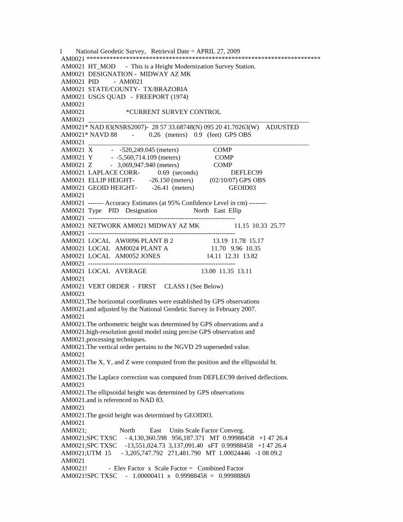
1 National Geodetic Survey, Retrieval Date = APRIL 28, 2009 AW4137 *********************************************************************** AW4137 DESIGNATION - J 1220 AW4137 PID - AW4137 AW4137 STATE/COUNTY- TX/BRAZORIA AW4137 USGS QUAD - WEST COLUMBIA (1980) AW4137 AW4137 *CURRENT SURVEY CONTROL AW4137 ___________________________________________________________________ AW4137* NAD 83(1986) - 29 08 33. (N) 095 39 21. (W) SCALED AW4137* NAVD 88 - 10.50 (+/-2cm) 34.4 (feet) VERTCON AW4137 ___________________________________________________________________ AW4137 GEOID HEIGHT- -26.84 (meters) GEOID03 AW4137 VERT ORDER - SECOND CLASS 0 (See Below) AW4137 AW4137.The horizontal coordinates were scaled from a topographic map and have AW4137.an estimated accuracy of +/- 6 seconds. AW4137 AW4137.The NAVD 88 height was computed by applying the VERTCON shift value to AW4137.the NGVD 29 height (displayed under SUPERSEDED SURVEY CONTROL.) AW4137.The vertical order pertains to the NGVD 29 superseded value. AW4137 AW4137.The geoid height was determined by GEOID03. AW4137 AW4137; North East Units Estimated Accuracy AW4137;SPC TXSC - 4,149,740. 925,320. MT (+/- 180 meters Scaled) AW4137 AW4137 SUPERSEDED SURVEY CONTROL AW4137 AW4137 NGVD 29 (??/??/92) 10.517 (m) 34.50 (f) ADJ UNCH 2 0 AW4137 AW4137.Superseded values are not recommended for survey control. AW4137.NGS no longer adjusts projects to the NAD 27 or NGVD 29 datums. AW4137.See file dsdata.txt to determine how the superseded data were derived. AW4137 AW4137_U.S. NATIONAL GRID SPATIAL ADDRESS: 15RTN416266(NAD 83) AW4137_MARKER: DB = BENCH MARK DISK AW4137_SETTING: 30 = SET IN A LIGHT STRUCTURE AW4137_SP_SET: CULVERT AW4137_STAMPING: J 1220 1973 AW4137_STABILITY: D = MARK OF QUESTIONABLE OR UNKNOWN STABILITY AW4137 AW4137 HISTORY - Date Condition Report By AW4137 HISTORY - 1973 MONUMENTED NGS AW4137 HISTORY - 1987 GOOD USPSQD AW4137 HISTORY - 1987 GOOD USPSQD AW4137 HISTORY - 1988 GOOD USPSQD AW4137 HISTORY - 1989 GOOD USPSQD AW4137 HISTORY - 19940416 GOOD USPSQD AW4137 AW4137 STATION DESCRIPTION AW4137 AW4137'DESCRIBED BY NATIONAL GEODETIC SURVEY 1973 AW4137'IN WEST COLUMBIA. AW4137'AT WEST COLUMBIA, 0.35 MILE NORTHWEST ALONG STATE HIGHWAY 36 FROM THE
AW4137'JUNCTION OF STATE HIGHWAY 35, 0.35 MILE SOUTHEAST ALONG STATE HIGHWAY AW4137'36 FROM THE JUNCTION OF FARM ROAD 1301, 0.1 MILE NORTHWEST OF THE AW4137'JUNCTION OF JACKSON STREET, 17 FEET SOUTHWEST OF THE CENTER LINE OF AW4137'THE SOUTHWEST LANES OF THE HIGHWAY, IN THE TOP AND 0.9 FOOT SOUTHEAST AW4137'OF THE NORTHWEST END OF THE SOUTHWEST CONCRETE HEADWALL OF A DOUBLE AW4137'BOX CULVERT, 22 FEET SOUTHEAST OF THE CENTER LINE OF THE DRIVEWAY TO AW4137'414 COLUMBIA DRIVE, AND ABOUT 0.5 FOOT LOWER THAN THE HIGHWAY. AW4137 AW4137 STATION RECOVERY (1987) AW4137 AW4137'RECOVERY NOTE BY US POWER SQUADRON 1987 (MVM) AW4137'RECOVERED IN GOOD CONDITION. AW4137 AW4137 STATION RECOVERY (1987) AW4137 AW4137'RECOVERY NOTE BY US POWER SQUADRON 1987 (LWM) AW4137'RECOVERED IN GOOD CONDITION. AW4137 AW4137 STATION RECOVERY (1988) AW4137 AW4137'RECOVERY NOTE BY US POWER SQUADRON 1988 (MVM) AW4137'RECOVERED IN GOOD CONDITION. AW4137 AW4137 STATION RECOVERY (1989) AW4137 AW4137'RECOVERY NOTE BY US POWER SQUADRON 1989 (JLH) AW4137'RECOVERED IN GOOD CONDITION. AW4137 AW4137 STATION RECOVERY (1994) AW4137 AW4137'RECOVERY NOTE BY US POWER SQUADRON 1994 AW4137'RECOVERED IN GOOD CONDITION.
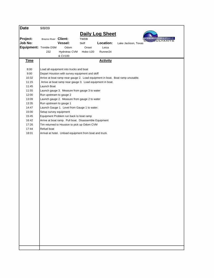
DateDaily Log Sheet
Project: Brazos River Client:Job No: Vessel: Skiff Location: Lake Jackson, TexasEquipment: Trimble DSM Odom Onset Leica
232 Hydrotrac CVM Hobo U20 Runner24 & CV100
Time Activity
8:009:00
10:3211:15 Arrive at boat ramp near gauge 3. Load equipment in boat.11:4511:5512:0013:0913:3514:4715:0015:4516:4217:2617:4418:01
Run upstream to gauge 2Launch gauge 2. Measure from gauge 2 to water
TWDB
Arrive at boat ramp near gauge 2. Load equipment in boat. Boat ramp unusable.
Launch BoatLaunch gauge 3. Measure from gauge 3 to water
9/8/09
Load all equipment into trucks and boatDepart Houston with survey equipment and skiff
Run upstream to gauge 1Launch Gauge 1. Level from Gauge 1 to water.Setup survey equipmentEquipment Problem run back to boat rampArrive at boat ramp. Pull boat. Disassemble EquipmentTim returned to Houston to pick up Odom CVMRefuel boatArrival at hotel. Unload equipment from boat and truck.
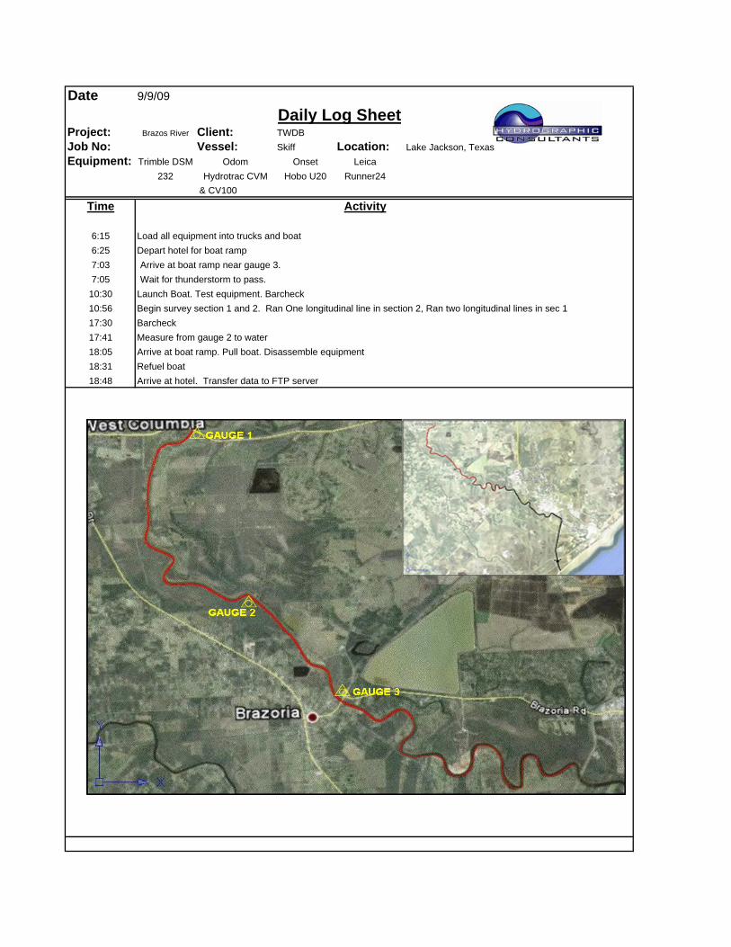
DateDaily Log Sheet
Project: Brazos River Client:Job No: Vessel: Skiff Location: Lake Jackson, TexasEquipment: Trimble DSM Odom Onset Leica
232 Hydrotrac CVM Hobo U20 Runner24 & CV100
Time Activity
6:156:257:037:05
10:3010:5617:3017:4118:0518:3118:48
BarcheckMeasure from gauge 2 to water
TWDB
Launch Boat. Test equipment. BarcheckBegin survey section 1 and 2. Ran One longitudinal line in section 2, Ran two longitudinal lines in sec 1
Arrive at boat ramp near gauge 3.Wait for thunderstorm to pass.
9/9/09
Load all equipment into trucks and boatDepart hotel for boat ramp
Arrive at boat ramp. Pull boat. Disassemble equipmentRefuel boatArrive at hotel. Transfer data to FTP server
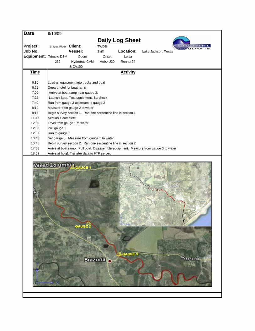
DateDaily Log Sheet
Project: Brazos River Client:Job No: Vessel: Skiff Location: Lake Jackson, TexasEquipment: Trimble DSM Odom Onset Leica
232 Hydrotrac CVM Hobo U20 Runner24 & CV100
Time Activity
6:106:257:007:257:408:128:17
11:4712:0012:3012:3213:4313:4517:3818:09
Begin survey section 1. Ran one serpentine line in section 1Section 1 complete
TWDB
Run from gauge 3 upstream to gauge 2Measure from gauge 2 to water
Arrive at boat ramp near gauge 3.Launch Boat. Test equipment. Barcheck
9/10/09
Load all equipment into trucks and boatDepart hotel for boat ramp
Level from gauge 1 to waterPull gauge 1Run to gauge 3Set gauge 3. Measure from gauge 3 to waterBegin survey section 2. Ran one serpentine line in section 2Arrive at boat ramp. Pull boat. Disassemble equipment. Measure from gauge 3 to waterArrive at hotel. Transfer data to FTP server.
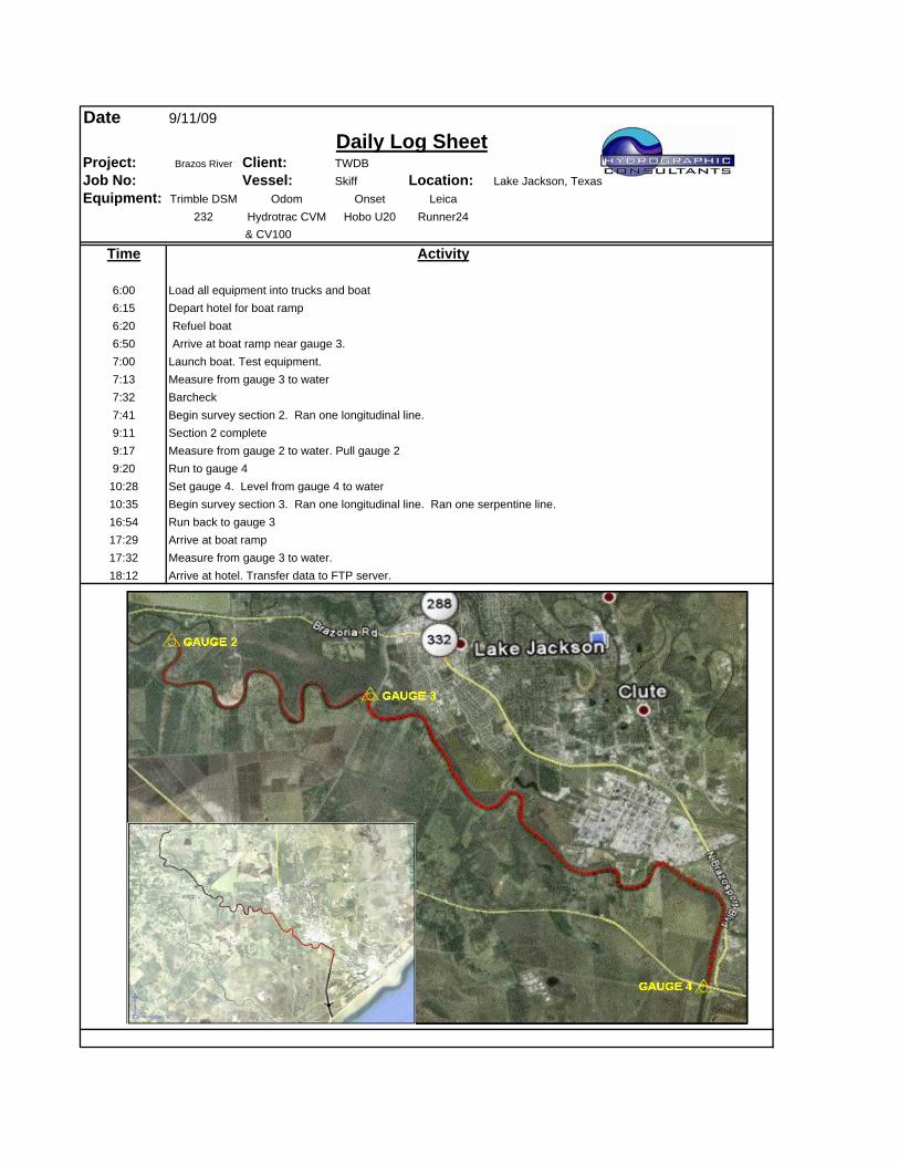
DateDaily Log Sheet
Project: Brazos River Client:Job No: Vessel: Skiff Location: Lake Jackson, TexasEquipment: Trimble DSM Odom Onset Leica
232 Hydrotrac CVM Hobo U20 Runner24 & CV100
Time Activity
6:006:156:206:507:007:137:327:419:119:179:20
10:2810:3516:5417:2917:3218:12 Arrive at hotel. Transfer data to FTP server.
Begin survey section 3. Ran one longitudinal line. Ran one serpentine line.Run back to gauge 3Arrive at boat rampMeasure from gauge 3 to water.
Section 2 completeMeasure from gauge 2 to water. Pull gauge 2Run to gauge 4Set gauge 4. Level from gauge 4 to water
9/11/09
Load all equipment into trucks and boatDepart hotel for boat ramp
BarcheckBegin survey section 2. Ran one longitudinal line.
TWDB
Launch boat. Test equipment.Measure from gauge 3 to water
Refuel boatArrive at boat ramp near gauge 3.
DateDaily Log Sheet
Project: Brazos River Client:Job No: Vessel: Skiff Location: Lake Jackson, TexasEquipment: Trimble DSM Odom Onset Leica
232 Hydrotrac CVM Hobo U20 Runner24 & CV100
Time Activity
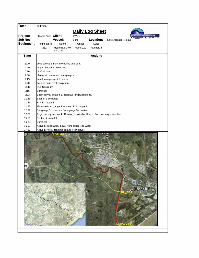
6:006:206:267:007:157:207:388:168:2311:4511:4611:5512:5712:5915:5616:2016:5517:50 Arrive at hotel. Transfer data to FTP server.
Begin survey section 4. Ran two longitudinal lines. Ran one serpentine line.Section 4 completeBarcheckArrive at boat ramp. Level from gauge 4 to water
Section 3 completeRun to gauge 3Measure from gauge 3 to water. Pull gauge 3Set gauge 5. Measure from gauge 5 to water
9/12/09
Load all equipment into trucks and boatDepart hotel for boat ramp
BarcheckBegin survey section 3. Ran two longitudinal line.
TWDB
Level from gauge 4 to waterLaunch boat. Test equipment.
Refuel boatArrive at boat ramp near gauge 4.
Run Upstream
DateDaily Log Sheet
Project: Brazos River Client:Job No: Vessel: Skiff Location: Lake Jackson, TexasEquipment: Trimble DSM Odom Onset Leica
232 Hydrotrac CVM Hobo U20 Runner24 & CV100
Time Activity
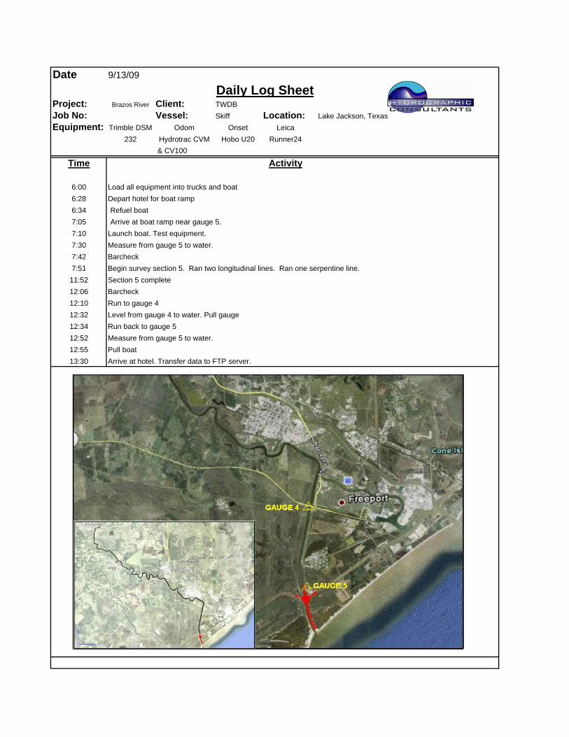
6:006:286:347:057:107:307:427:51
11:5212:0612:1012:3212:3412:5212:5513:30
BarcheckBegin survey section 5. Ran two longitudinal lines. Ran one serpentine line.
TWDB
Launch boat. Test equipment.Measure from gauge 5 to water.
Refuel boatArrive at boat ramp near gauge 5.
9/13/09
Load all equipment into trucks and boatDepart hotel for boat ramp
Section 5 completeBarcheckRun to gauge 4Level from gauge 4 to water. Pull gaugeRun back to gauge 5Measure from gauge 5 to water.Pull boatArrive at hotel. Transfer data to FTP server.
DateDaily Log Sheet
Project: Brazos River Client:Job No: Vessel: Skiff Location: Lake Jackson, TexasEquipment: Trimble DSM Odom Onset Leica
232 Hydrotrac CVM Hobo U20 Runner24 & CV100
Time Activity
7:458:008:109:409:45
TWDB
Clean up equipment and boat
Refuel boatArrive in Houston at office
9/14/09
Load all equipment into trucks and boatDepart from Lake Jackson